1. Introduction
With the rapid development of 5G communication technologies, dielectric-filled resonator filters have experienced a resurgence in interest due to their compact form factor, cost efficiency, and superior Q-factor [
1,
2,
3,
4,
5,
6]. Among these, multi-mode dielectric-filled resonator filters are particularly favored for their ability to combine high performance with compactness and lightweight design, making them well-suited for applications with stringent performance requirements [
7,
8]. However, the integration of higher-order pole modes can introduce complexities in terms of independent control, and the presence of spurious modes may compromise the overall performance when compared to fundamental-mode filters [
9].
Half-mode (HM) resonators, derived from the fundamental mode, offer a promising solution to the challenges associated with multi-mode resonators. The initial implementations of HM resonators utilized substrate integrated waveguides (SIWs), where the aspect ratio of the open apertures (OAs) is greater than 10 to prevent the fringe effects, resulting in energy leakage, undesired frequency shifts, and increased losses [
10,
11,
12,
13,
14,
15]. This high-aspect-ratio SIW configuration is also applied in the design of quarter-mode resonators [
16,
17,
18,
19]. To mitigate these issues, the design of virtual magnetic walls (VMWs) has become essential. This study presents a comprehensive design methodology for the VMW, based on transmission line theory. Specifically, the OAs of SIW HM resonators are modeled as open-circuit terminals of quarter-wavelength transmission lines, with the other terminal being short-circuited. Given the large-aspect-ratio limitation of the OAs, these resonators typically operate in the X- and Ku-bands. The proposed work addresses this aspect ratio constraint, enabling the HM resonator to function efficiently at lower frequencies.
In this paper, a novel design for HM dielectric-filled resonators utilizing VMWs is proposed. The fundamental operating principle of the HM dielectric-filled resonator is clearly articulated, and the design approach for VMWs is introduced, effectively overcoming the limitations imposed by the large aspect ratio of the OAs. The proposed method results in a 37% reduction in both size and weight, making it particularly suitable for flexible dimensional design of bandpass filters (BPFs). To demonstrate the effectiveness of this design, compact inline and folded fourth-order HM dielectric-filled BPFs operating in the S-band are designed, analyzed, and fabricated, exhibiting excellent out-of-band suppression. Measurement results confirm the validity of the proposed approach and highlight its practical advantages.
2. Half-Mode Dielectric-Filled Resonator
2.1. Principle of the Half-Mode Dielectric-Filled Resonator
Theoretically, traditional rectangular dielectric-filled resonators can be constructed using a dielectric ceramic block with silver-coated surfaces. In this section, the silver-coated surfaces are modeled as perfect electric walls (PEWs), as shown in
Figure 1a. The dimensions of the resonator are defined by its length (
), width (
), and height (
). The resonant frequency of the cavity with these boundary conditions can be determined using the following formula [
20]:
where
represents the speed of light.
denotes the permittivity, and
,
, and
represent the wave numbers.
In
Figure 1b, one of the PEW surfaces from
Figure 1a is replaced with perfect magnetic wall (PMW) surfaces. In this configuration, the resonant frequency for operation in the
mode can be determined as follows:
The resonant frequency (
) of the cavity with partially PMW surfaces is lower than that of the fully PEW cavity operating in the
mode. To match the resonant frequency with that of the fully PEW cavity, the length (
) typically needs to be halved, which is a key feature of the HM dielectric-filled resonator design.
Figure 2 shows the top-view electric field distributions for both the full-mode (FM) and HM resonators operating in the
mode. It should be emphasized that the field distribution of the half-mode resonator is obtained under the PMW conditions.
2.2. Design of the Half-Mode Dielectric-Filled Resonator
Figure 3 shows the configuration of the HM dielectric-filled resonator and its top-view electric field distribution of the
mode. The relative permittivity of the ceramic is 20. Additionally, the loss tangent of the ceramic is determined to be 0.0005. The length (
) is approximately half of that of the FM resonator. All surfaces of the HM dielectric-filled resonator are silver-coated, except for the open apertures (OAs), which exhibit slight field leakage. The OA is identified as the virtual magnetic wall (VMW). The dimensions of the HM dielectric-filled resonator are optimized based on the resonant frequency of the FM dielectric-filled resonator. The electric field distribution is obtained through HFSS eigenmode simulations. An airbox is placed a 0.1 wavelength from the resonator surface, with its boundary conditions set as PEWs.
Figure 4 presents the variation in the resonant frequency of the HM dielectric-filled resonator with respect to the length (
).
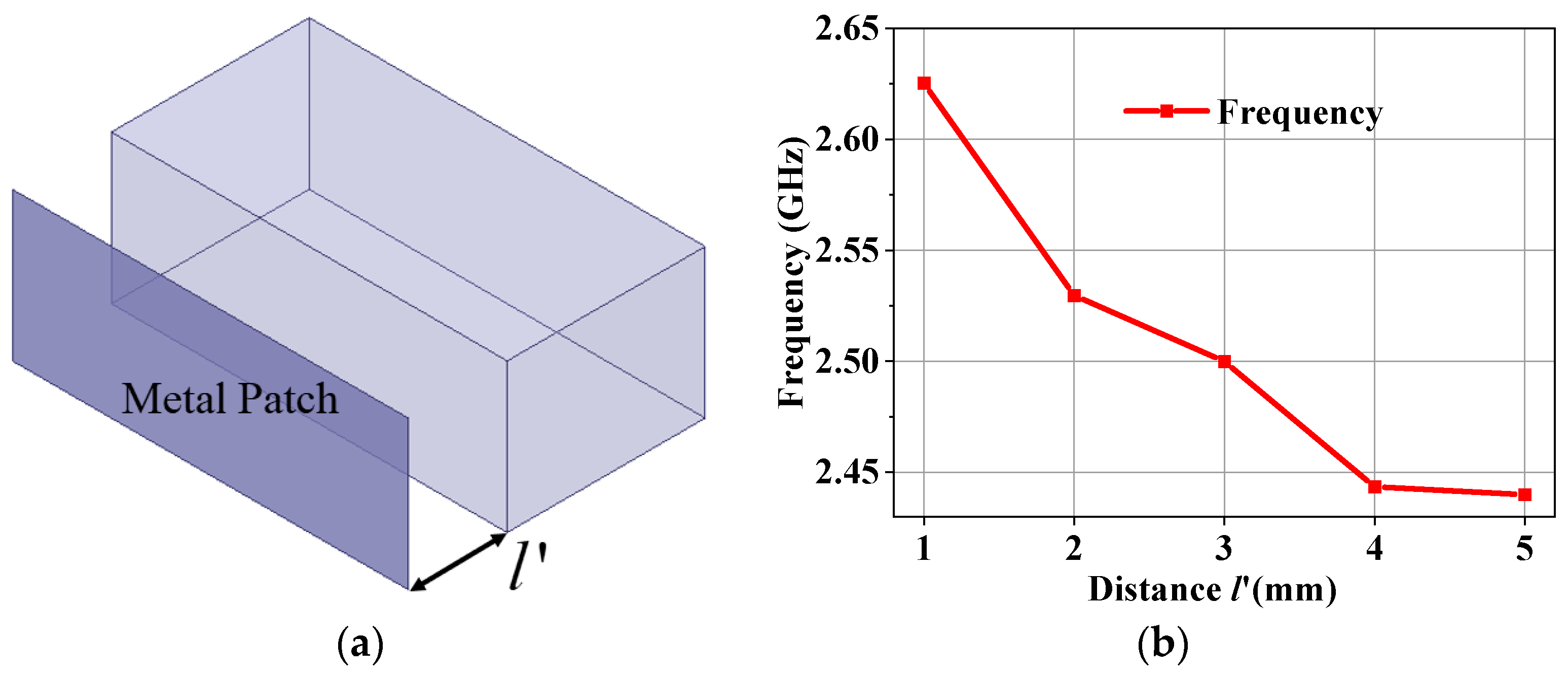
Due to the sensitivity of the OA to the surrounding environment, this work further investigates the effect of nearby metal patches on the resonant frequency of the HM dielectric-filled resonator.
Figure 5a shows the configuration of the HM dielectric-filled resonator with a metal patch. The variable
denotes the distance between the metal patch and the OA of the resonator.
Figure 5b illustrates the resonant frequency of the HM resonator with metal patches at varying distances. As
increases, the resonant frequency gradually decreases and eventually stabilizes.
3. The Application of Half-Mode Dielectric-Filled Resonator for Bandpass Filter Design
The HM dielectric-filled resonator can be cascaded with the FM resonator to design bandpass filters (BPFs). The design approach is similar to that of traditional cavity filters [
21,
22,
23,
24].
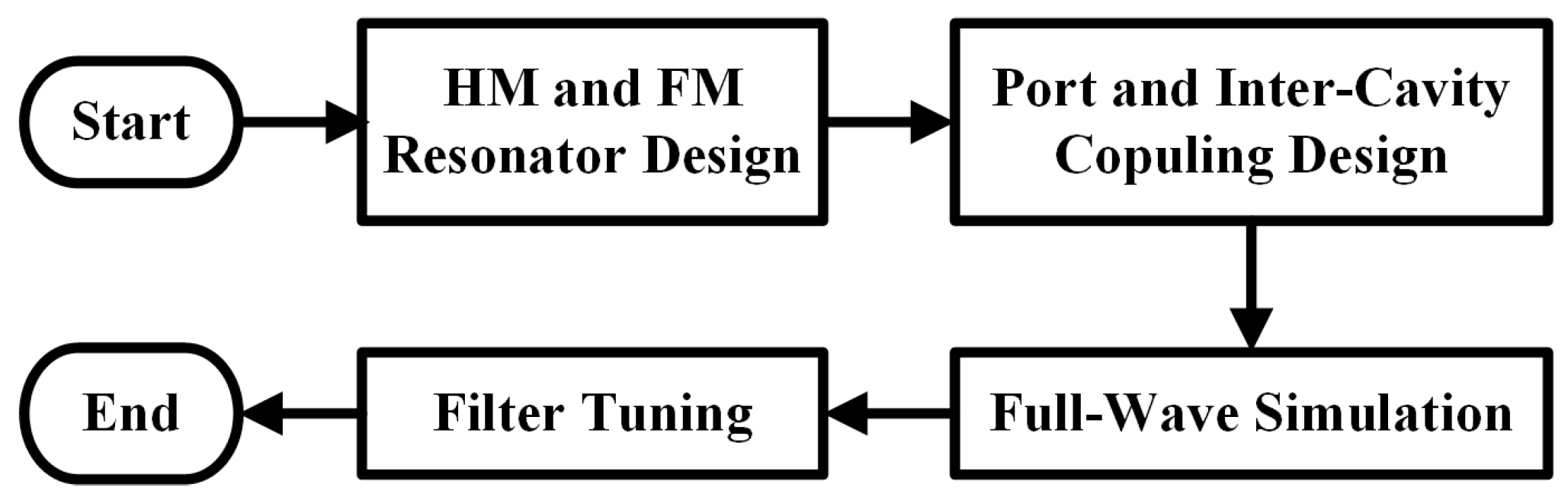
Figure 6 shows the design process of the bandpass filter. The design of the HM dielectric-filled resonator was completed in the previous section. The FM dielectric-filled resonator can be designed using traditional methods. This section will complete the port coupling and inter-cavity coupling design. The full-wave simulation and tuning of the filter are carried out using HFSS and CST Filter Designer 3D, respectively. These two processes are not elaborated upon here.
3.1. Port Coupling
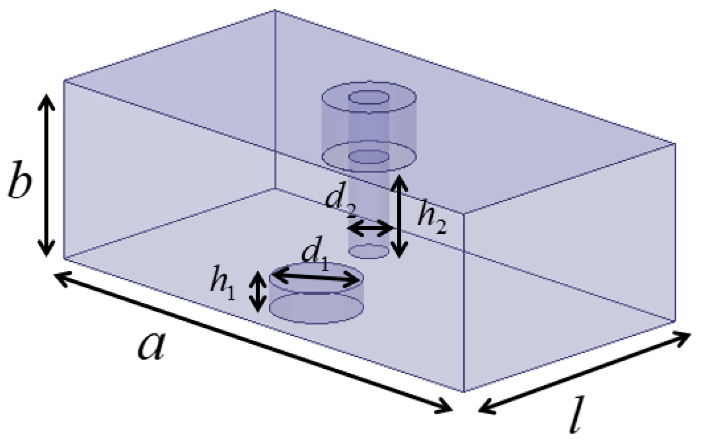
Figure 7 depicts the port coupling structure, which is excited using coaxial probes. To ensure that the resonator operates within the center frequency band, the blind hole dimensions (
) and (
) are used for tuning. The dimensions (
) and (
) of the coupling probe are employed to precisely adjust the coupling strength. The port coupling is characterized by the group delay of
, which is expressed by the following formula [
25]:
In this context,
represents the group delay at the center frequency
.
represents the loaded quality factor, which is calculated as reference in [
26]. The group delay of the port coupling, which corresponds to the coaxial probe dimensions (
), serves as the initial values for tuning the port coupling structure to achieve the desired performance.
3.2. Inter-Cavity Coupling
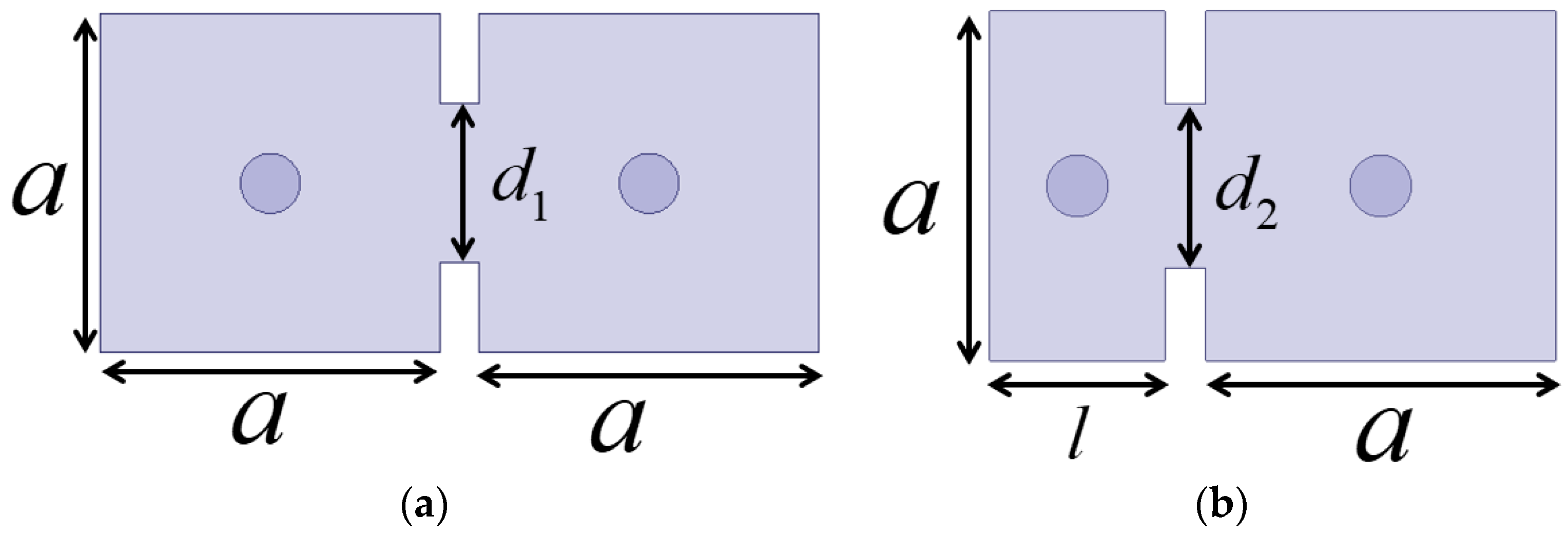
To ensure the proper functioning of the HM dielectric-filled resonator, the inter-cavity coupling avoids the VMW and adopts conventional iris coupling methods.
Figure 8a illustrates the coupling configuration where both cavities are FM resonators, while
Figure 8b depicts the coupling configuration between an FM resonator and an HM resonator. The sizes of the coupling irises
and
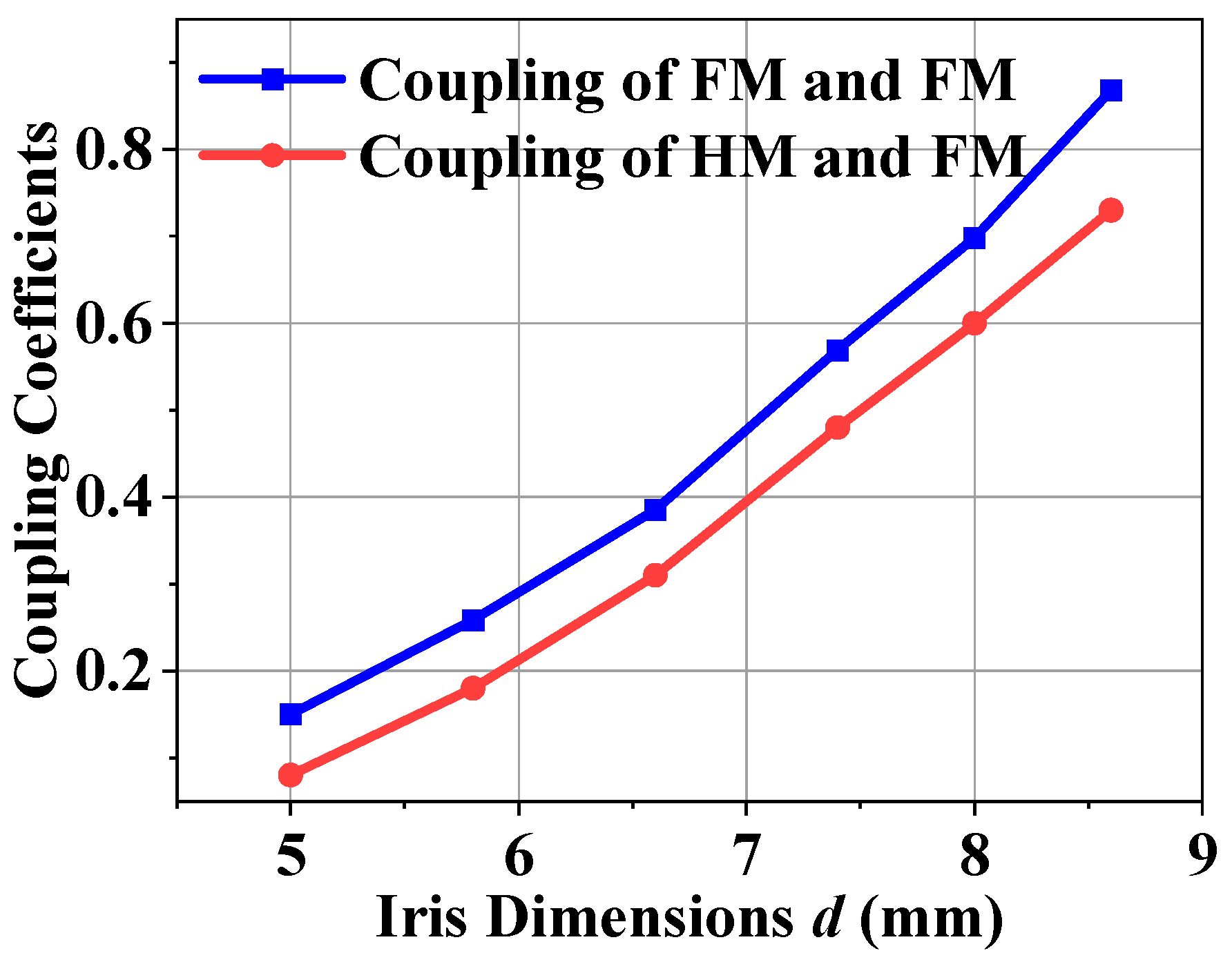
determine the magnitude of the coupling coefficient. The coupling coefficient of the inter-cavity can be defined as follows [
27]:
where
and
are the odd-mode and even-mode resonant frequencies of the two coupled resonators, respectively.
Figure 9 shows the inter-cavity coupling coefficients as a function of iris dimensions. Inter-cavity coupling is achieved through an iris in an electric wall iris to ensure the proper functioning of the VMW in the HM resonator. The blue curve represents the coupling between two FM resonators, while the red curve corresponds to the coupling between an FM resonator and an HM resonator. The results indicate that the coupling coefficient increases as the iris dimensions grow for both cases. However, the coupling strength for FM-FM resonators is consistently higher than that for FM-HM resonators across the entire range of iris dimensions.
3.3. Fourth-Order Inline and Folded Bandpass Filter
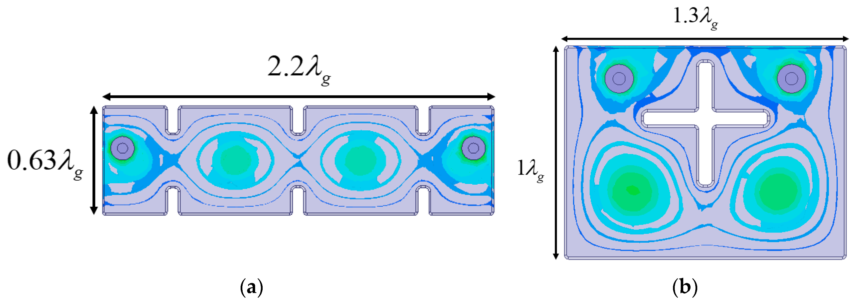
Figure 10 illustrates the configuration and top-view electric field distribution of the simulated fourth-order inline and folded BPFs. The dimensions of both filters are indicated in waveguide wavelengths (
) in
Figure 10, with the height of both the inline and folded filters being
. In both filter configurations, port coupling is realized using a coaxial probe connected to the HM resonators. The connection between resonator 1 and resonator 4 in the folded BPF ensures structural integrity and remains deformation-free throughout the manufacturing process.
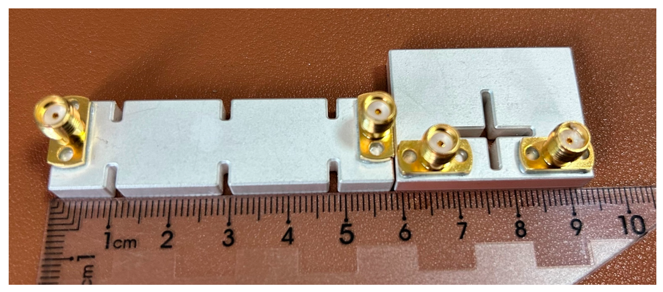
Figure 11 presents images of the fabricated inline and folded BPFs. SMA connectors are used to facilitate port coupling via a welding technique. The frequency responses, including both simulated and measured data, are shown in
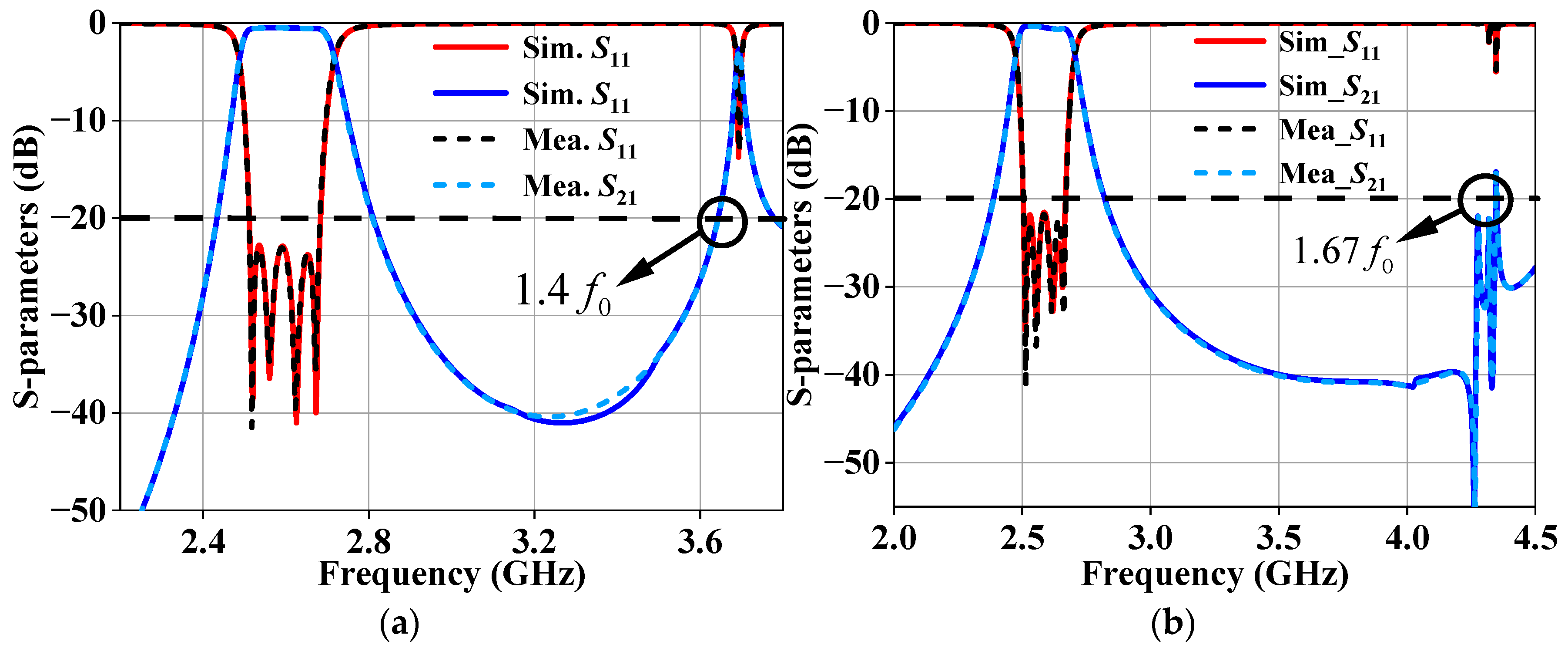
Figure 12. Both the inline and folded BPFs exhibit approximately symmetric responses with a center frequency of 2.6 GHz and a bandwidth of 160 MHz. The simulated and measured frequency response curves demonstrate excellent agreement, with the passband of the BPFs ranging from 2.515 GHz to 2.675 GHz. The in-band return loss of the inline BPF is 22 dB for both simulated and measured results, while the minimum insertion loss is 0.5 dB for simulation and 0.7 dB for the measurement. Out-of-band suppression of the inline BPF reaches 20 dB at 1.4
. Similarly, the in-band return loss of the folded BPF is 22 dB for the simulation and 20 dB for the measurement, with a minimum insertion of 0.6 dB for the simulation and 0.8 dB for the measurement. Out-of-band suppression of the folded BPFs reaches 20 dB at 1.67
. Both the inline and folded filters exhibit a volume reduction of approximately 20% compared to the full-mode filter. This design offers flexibility in dimensional design and can be used in scenarios with specific size constraints, reducing the size without compromising the filtering performance.
The inline filter exhibits parasitic behavior at 3.7 GHz, whereas the folded filter does not show parasitic behavior at 3.7 GHz. This study explains the above phenomena using the eigenmode method.
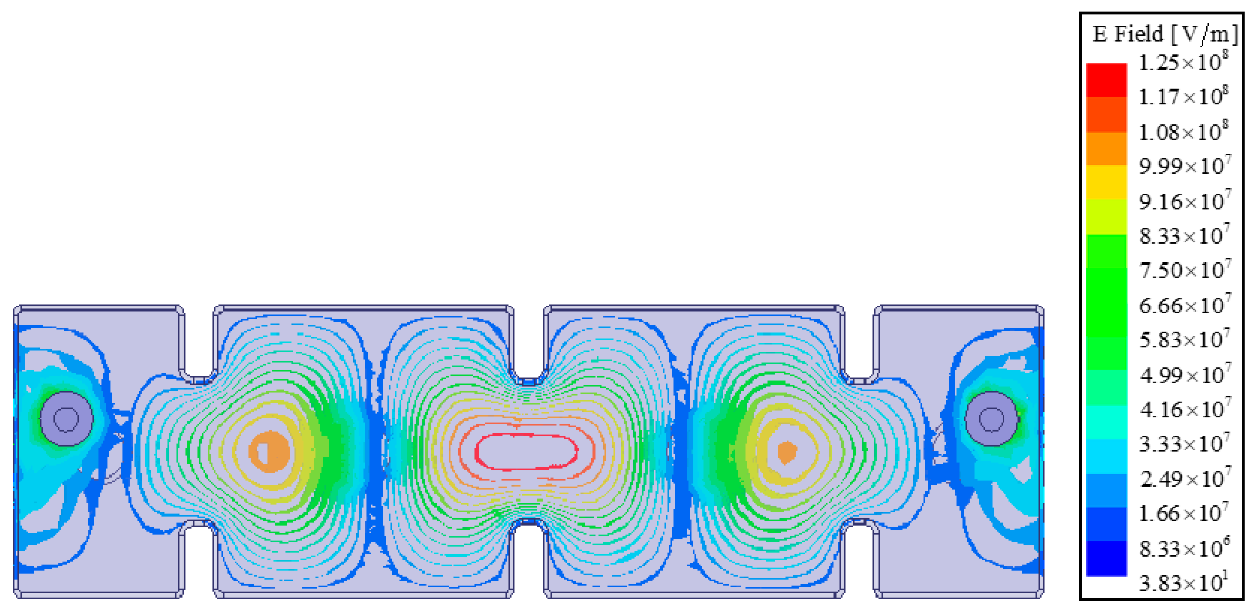
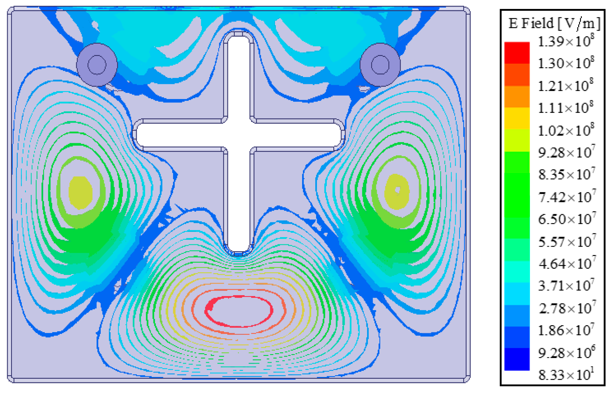
Figure 13 illustrates the electric field distribution of the spurious mode at 3.69 GHz in the inline filter, while
Figure 14 shows the electric field distribution of the same spurious mode at 3.76 GHz in the folded filter. The field strength of the spurious mode is higher at the ports of the inline filter, leading to parasitic behavior. However, the field strength of the spurious mode is lower at the ports of the folded filter, preventing spurious behaviors.
3.4. Fourth-Order Folded Bandpass Filter with Transmission Zeros
This design is compatible with transmission zeros (TZs) technology, enhancing out-of-band rejection.
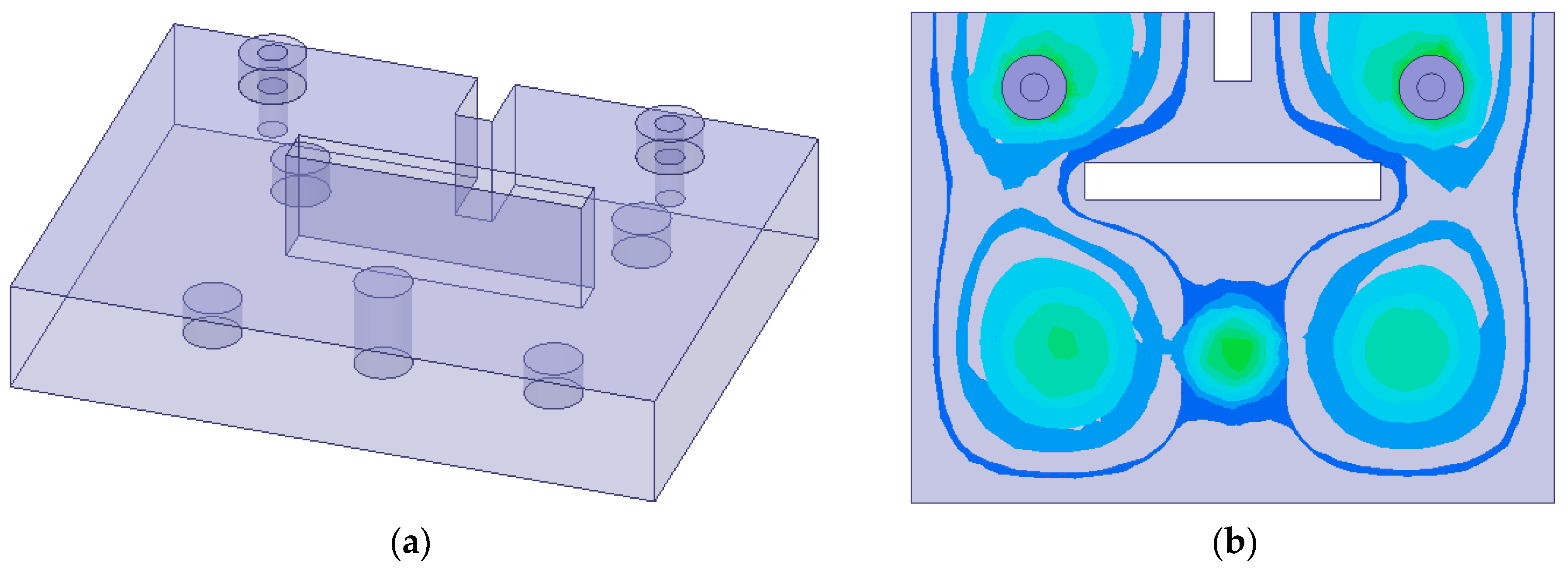
Figure 15 shows the configuration and top-view electric field distribution of the fourth-order BPFs with TZs. The filter with a transmission zero has the same dimensions as the folded filter.
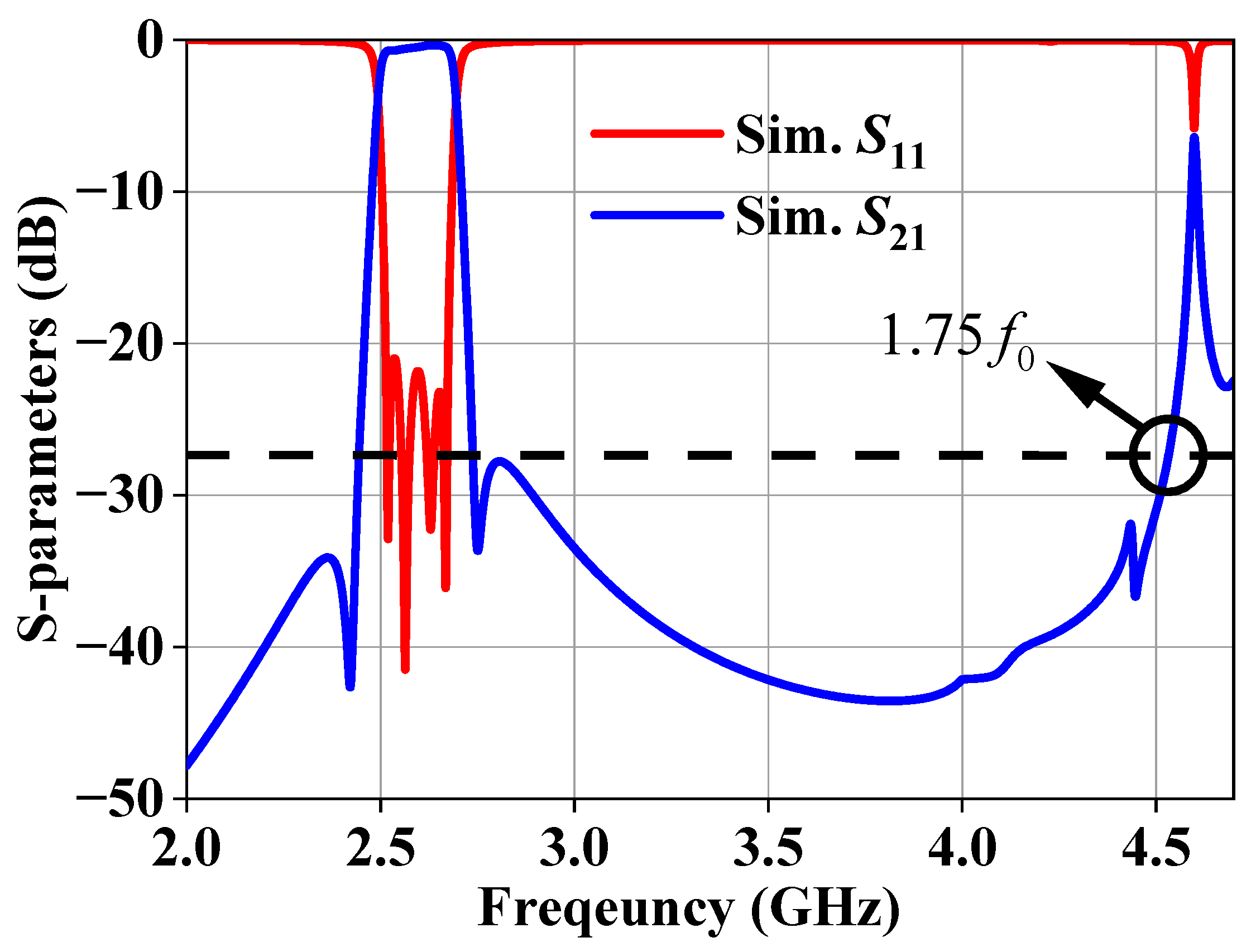
Figure 16 presents the corresponding frequency response. The stopband suppression of the BPFs reaches 1.75
with 27 dB. To further highlight the advantages,
Table 1 provides a detailed comparison between filters based on dielectric-filled resonators. This work is notable for its compact size, lightweight structure, and superior out-of-band suppression.
4. Results
This article presents a compact HM dielectric-filled resonator based on VMWs. The miniaturization principle of the HM dielectric-filled resonator is discussed, with the OAs serving as VMWs. The HM dielectric-filled resonator achieves a 37% reduction in both volume and weight. By integrating HM and FM resonators, flexibility in filter design is significantly enhanced, enabling the customization of filter characteristics to meet specific requirements. To validate the effectiveness of the proposed approach, fourth-order inline and folded BPFs incorporating both HM and FM resonators were fabricated and tested. The experimental results demonstrate that the proposed BPFs achieve superior out-of-band rejection, reduced insertion loss, and enhanced design flexibility. With high performance, compactness, and design flexibility, the HM dielectric-filled BPFs are well suited for base station filters in 5G applications.
Author Contributions
Conceptualization, Z.D. and J.P.; methodology, Z.D. and J.P.; software, Z.D. and J.P.; validation, Z.D. and J.P.; formal analysis, Z.D. and J.P.; investigation, Z.D. and J.P.; writing—original draft preparation, Z.D. and J.P.; writing—review and editing, Z.D. and J.P.; visualization, Z.D. and J.P.; supervision, Z.D. and J.P. All authors have read and agreed to the published version of the manuscript.
Funding
This research was funded by the Aeronautical Science Fund under Grant ASFC-20220005080001.
Data Availability Statement
Data are available upon request from the corresponding author.
Acknowledgments
We appreciate the Jiangsu Jiangjia Electronics Co., Ltd.
Conflicts of Interest
The authors declare no conflicts of interest.
References
- Zhang, Y.; Seyfert, F.; Wu, K.-L. Dispersive Box Section and Its Applications to Quasi-TEM Mode Monoblock Dielectric Filters. IEEE Trans. Microw. Theory Technol. 2023, 71, 1136–1147. [Google Scholar] [CrossRef]
- Yin, Y.; Zhou, T.; Xie, Y.; Shen, W.; Zhang, Q.; Zhang, X. A Quasi-Box-Like Dielectric Filter Sharing a Cavity with Wide Stopband. IEEE Microw. Wirel. Compon. Lett. 2024, 34, 1075–1078. [Google Scholar]
- Xu, Z.; Wu, Y.; Li, S.; Wang, Z.; Wang, W. Exhaustive Design and Realization for In-Line Topology Quasi-TEM Mode Die-lectric Waveguide Filter With Dispersive Couplings. IEEE Trans. Circuits Syst. II Exp. Briefs 2024, 71, 3333–3337. [Google Scholar]
- Zhang, Y.; Chen, Y.; Wu, K.-L. A Dispersive Quadruplet Structure for Monoblock Dielectric Resonator Filters. IEEE Trans. Microw. Theory Technol. 2022, 70, 3105–3114. [Google Scholar]
- Zhou, Y.-K.; Qin, W.; Yang, W.-W.; Chen, J.-X. Multiband Dielectric Waveguide Bandpass Filters Based on Frequency Mapping Technique. IEEE Trans. Microw. Theory Technol. 2025, 73, 1062–1072. [Google Scholar] [CrossRef]
- Qin, W.; Zhou, Y.-K.; Yang, W.-W.; Chen, J.-X. Dielectric Waveguide Bandpass Filters With Multiple Transmission Zeros by Constructing Cascaded-Trisection Coupling Structures. IEEE Trans. Microw. Theory Technol. 2024, 72, 4218–4228. [Google Scholar] [CrossRef]
- Wang, Z.; Wu, Y.; Xu, Z.; Yao, Y.; Wang, W. Adjustable Triple-Band Triple-Mode Dielectric Waveguide Filter With Multiple Transmission Zeros. IEEE Microw. Wirel. Compon. Lett. 2024, 34, 619–622. [Google Scholar] [CrossRef]
- Chen, Y.; Wu, K.-L. Metal-Dielectric Coaxial Dual-Mode Resonator Bandpass Filters. IEEE Trans. Microw. Theory Technol. 2024, 72, 670–679. [Google Scholar]
- Chen, Y.; Zhang, Y.; Wu, K.-L. A Dual-Mode Monoblock Dielectric Bandpass Filter Using Dissimilar Fundamental Modes. IEEE Trans. Microw. Theory Technol. 2021, 69, 3811–3819. [Google Scholar]
- Hong, W.; Liu, B.; Wang, Y.; Lai, Q.; Tang, H.; Yin, X.; Dong, Y.; Zhang, Y.; Wu, K. Half Mode Substrate Integrated Waveguide: A New Guided Wave Structure for Microwave and Millimeter Wave Application. In Proceedings of the 2006 Joint 31st International Conference on Infrared Millimeter Waves and 14th International Conference on Teraherz Electronics, Shanghai, China, 18–22 September 2006; p. 219. [Google Scholar]
- Cheng, Y.; Hong, W.; Wu, K. Half Mode Substrate Integrated Waveguide (HMSIW) Directional Filter. IEEE Microw. Wirel. Technol. Lett. 2007, 17, 504–506. [Google Scholar]
- Wu, L.-S.; Zhou, X.-L.; Yin, W.-Y.; Liu, C.-T.; Zhou, L.; Mao, J.-F.; Peng, H.-L. A New Type of Periodically Loaded Half-Mode Substrate Integrated Waveguide and Its Applications. IEEE Trans. Microw. Theory Technol. 2010, 58, 882–893. [Google Scholar]
- Chen, F.; Song, K.; Hu, B.; Fan, Y. Compact Dual-band Bandpass Filter Using HMSIW Resonator and Slot Perturbation. IEEE Microw. Wirel. Technol. Lett. 2014, 24, 686–688. [Google Scholar] [CrossRef]
- Zhu, F.; Luo, G.Q.; Liao, Z.; Dai, X.W.; Wu, K. Compact Dual-Mode Bandpass Filters Based on Half-Mode Sub-strate-Integrated Waveguide Cavities. IEEE Microw. Wirel. Technol. Lett. 2021, 31, 441–444. [Google Scholar] [CrossRef]
- Zhou, K.; Zhou, C.-X.; Wu, W. Dual-Mode Characteristics of Half-Mode SIW Rectangular Cavity and Applications to Dual-Band Filters with Widely Separated Passbands. IEEE Trans. Microw. Theory Technol. 2018, 66, 4820–4829. [Google Scholar] [CrossRef]
- Li, M.; Ji, Q.; Chen, C.; Chen, W.; Zhang, H. A Triple-Mode Bandpass Filter With Controllable Bandwidth Using QMSIW Cavity. IEEE Microw. Wirel. Technol. Lett. 2018, 28, 654–656. [Google Scholar] [CrossRef]
- Huang, X.; Zhou, L.; Xu, J.-X.; Zhang, X.Y.; Mao, J.-F. BCB-Based Thin-Film Ka-Band Quarter-Mode SIW Packaged Filters With Ultrawide Stopband and Independently Controlled TZs. IEEE Trans. Microw. Theory Technol. 2022, 70, 4389–4398. [Google Scholar] [CrossRef]
- Jin, C.; Shen, Z. Compact Triple-Mode Filter Based on Quarter-Mode Substrate Integrated Waveguide. IEEE Trans. Microw. Theory Technol. 2014, 62, 37–45. [Google Scholar] [CrossRef]
- Moscato, S.; Tomassoni, C.; Bozzi, M.; Perregrini, L. Quarter-Mode Cavity Filters in Substrate Integrated Waveguide Technology. IEEE Trans. Microw. Theory Technol. 2016, 64, 2538–2547. [Google Scholar] [CrossRef]
- Pozar, D.M. Microwave Engineering, 4th ed.; John Wiley & Sons: New York, NY, USA, 2011. [Google Scholar]
- Xie, Y.; Chen, F.-C.; Chu, Q.-X. Tunable Cavity Filter and Diplexer Using In-Line Dual-Post Resonators. IEEE Trans. Microw. Theory Technol. 2022, 70, 3188–3199. [Google Scholar] [CrossRef]
- Xie, Y.; Chen, F.-C.; Chu, Q.-X. Triple-Band Bandpass Filter and Triplexer Using Quad-Ridge Cavity Resonators. IEEE Trans. Microw. Theory Technol. 2021, 69, 3832–3841. [Google Scholar] [CrossRef]
- Kashyap, R.S.; Kumar, G. A simple design for waveguide cavity filters with improved stopband performance. In Proceedings of the 2009 Asia Pacific Microwave Conference, Singapore, 7–10 December 2009; pp. 697–700. [Google Scholar]
- Huong, T.T.T.; Tuan, A.D.; Thao, T.T.; Vu, V.Y. A Novel Resonator Structure to Improve Power Handling Capacity in Iris Coupled Cavity Filter. In Proceedings of the 2019 International Conference on Advanced Technologies for Communications (ATC), Hanoi, Vietnam, 17–19 October 2019; pp. 98–102. [Google Scholar]
- Hong, J.S.; Lancaster, M.J. Microstrip Filters for RF/Microwave Applications; Wiley: New York, NY, USA, 2001; pp. 8–10. [Google Scholar]
- Zheng, Y.; Tian, H.; Dong, Y. Miniaturized, Wide Stopband Filter Based on Shielded Capacitively Loaded SIW Resonators. Chin. J. Electron. 2024, 33, 456–462. [Google Scholar] [CrossRef]
- Howe, G.W.O. Coupling and coupling coefficients. Wirel. Eng. 1932, 9, 485–486. [Google Scholar]
- Zhu, B.; Lu, D.; Ji, X.; Yu, M. A novel stacked ceramic-monoblock filter with highly flexible transmission zero pair. IEEE Microw. Wirel. Technol. Lett. 2023, 33, 383–386. [Google Scholar] [CrossRef]
- Xie, Y.; Chen, F.-C.; Chu, Q.-X. Inline box-like dielectric filters with asymmetric and symmetric responses. IEEE Trans. Microw. Theory Technol. 2023, 71, 2522–2531. [Google Scholar] [CrossRef]
- Huang, Z.; Cheng, Y.; Zhang, Y. Dual-Mode Dielectric Waveguide Filters with Controllable Transmission Zeros. IEEE Microw. Wirel. Technol. Lett. 2021, 31, 449–452. [Google Scholar] [CrossRef]
- Wu, Y.; Jin, L.; Lu, Z. A triple-quasi-TEM-resonance dielectric cavity for bandpass filter design. IEEE Microw. Wirel. Compon. Lett. 2022, 32, 950–952. [Google Scholar] [CrossRef]
Figure 1.
Configuration of the dielectric-filled resonator. (a) All surfaces are modeled as PEWs. (b) All surfaces are modeled as PEWs, except for the PMWs indicated.
Figure 1.
Configuration of the dielectric-filled resonator. (a) All surfaces are modeled as PEWs. (b) All surfaces are modeled as PEWs, except for the PMWs indicated.
Figure 2.
Top-view electric field distribution of the mode. (a) Full-mode resonator. (b) Half-mode resonator with PMW.
Figure 2.
Top-view electric field distribution of the mode. (a) Full-mode resonator. (b) Half-mode resonator with PMW.
Figure 3.
(a) Configuration of the HM dielectric-filled resonator. (b) Top view of the electric field distribution of the mode.
Figure 3.
(a) Configuration of the HM dielectric-filled resonator. (b) Top view of the electric field distribution of the mode.
Figure 4.
Frequency of the half-mode dielectric-filled resonator with different lengths ().
Figure 4.
Frequency of the half-mode dielectric-filled resonator with different lengths ().
Figure 5.
(a) Configuration of the half-mode dielectric-filled resonator with a metal patch. (b) Frequency of the half-mode resonator with metal patches at different distances.
Figure 5.
(a) Configuration of the half-mode dielectric-filled resonator with a metal patch. (b) Frequency of the half-mode resonator with metal patches at different distances.
Figure 6.
Design process of bandpass filters cascaded with half-mode and full-mode dielectric-filled resonators.
Figure 6.
Design process of bandpass filters cascaded with half-mode and full-mode dielectric-filled resonators.
Figure 7.
Configuration of the port coupling mechanism for the half-mode dielectric-filled resonator.
Figure 7.
Configuration of the port coupling mechanism for the half-mode dielectric-filled resonator.
Figure 8.
(a) Configuration of the inter-cavity coupling between full-mode resonators. (b) Configuration of the inter-cavity coupling between the full-mode and half-mode resonators.
Figure 8.
(a) Configuration of the inter-cavity coupling between full-mode resonators. (b) Configuration of the inter-cavity coupling between the full-mode and half-mode resonators.
Figure 9.
Coupling coefficients of the inter-cavity coupling as a function of iris dimensions.
Figure 9.
Coupling coefficients of the inter-cavity coupling as a function of iris dimensions.
Figure 10.
Configuration and electric field distribution of (a) inline fourth-order passband filters and (b) folded fourth-order passband filters.
Figure 10.
Configuration and electric field distribution of (a) inline fourth-order passband filters and (b) folded fourth-order passband filters.
Figure 11.
Configuration of the fabricated fourth-order inline and folded dielectric-filled bandpass filters.
Figure 11.
Configuration of the fabricated fourth-order inline and folded dielectric-filled bandpass filters.
Figure 12.
Frequency response of the fourth-order dielectric-filled bandpass filters. (a) Inline and (b) folded.
Figure 12.
Frequency response of the fourth-order dielectric-filled bandpass filters. (a) Inline and (b) folded.
Figure 13.
The electric field distribution of the spurious mode in the inline filter.
Figure 13.
The electric field distribution of the spurious mode in the inline filter.
Figure 14.
The electric field distribution of the spurious mode in the folded filter.
Figure 14.
The electric field distribution of the spurious mode in the folded filter.
Figure 15.
Simulated fourth-order folded dielectric-filled bandpass filters. (a) Configuration. (b) Top-view electric field distribution.
Figure 15.
Simulated fourth-order folded dielectric-filled bandpass filters. (a) Configuration. (b) Top-view electric field distribution.
Figure 16.
Frequency response of the simulated fourth-order folded dielectric-filled bandpass filters with two transmission zeros.
Figure 16.
Frequency response of the simulated fourth-order folded dielectric-filled bandpass filters with two transmission zeros.
Table 1.
Comparison performance of the advanced technology.
Table 1.
Comparison performance of the advanced technology.
| Ref. | Pole |
(GHz) | FBW
(%) | IL
(dB) | RL
(dB) | Size
) | Rejection
(dB)/S.B | Unloaded
Q-Factor |
|---|
| [28] | 5 | 2.6 | 5.7 | 0.62 | 18 | 0.74 | | 1400 |
| [29] | 4 | 3.5 | 5 | 0.3 | 10 | 1.16 | | 1400 |
| [30] | 4 | 3.5 | 5.7 | 1 | 18 | 0.42 | | 625 |
| [31] | 4 | 3.5 | 5.7 | 0.53 | 20 | 1.2 | | 700 |
| Pro.1 | 4 | 2.6 | 6.2 | 0.7 | 22 | 0.29 | | 645 |
| Pro.2 | 4 | 2.6 | 6.2 | 0.8 | 20 | 0.28 | | 645 |
| Disclaimer/Publisher’s Note: The statements, opinions and data contained in all publications are solely those of the individual author(s) and contributor(s) and not of MDPI and/or the editor(s). MDPI and/or the editor(s) disclaim responsibility for any injury to people or property resulting from any ideas, methods, instructions or products referred to in the content. |
© 2025 by the authors. Licensee MDPI, Basel, Switzerland. This article is an open access article distributed under the terms and conditions of the Creative Commons Attribution (CC BY) license (https://creativecommons.org/licenses/by/4.0/).


