

Fuzzy Battery Manager: Charging and Balancing Rechargeable Battery Cells with Fuzzy Logic


Abstract
1. Introduction
2. Background and Related Work
- Li-ion and LiPo batteries: These widely used batteries have distinct charging profiles, characterized by unique voltage and current settings. Ensuring precise adherence to these settings is critical, as any deviation—such as applying a LiPo-optimized charging current to a Li-ion cell—can lead to significant safety hazards, including overheating, reduced efficiency, and potential failure.
- Unique characteristics of different chemistries:
- °
- Nickel–Cadmium (NiCd) cells: Known for their “memory effect,” these batteries can suffer from reduced capacity if not fully discharged before recharging, which complicates their management [9].
- °
- Pulse charging responses: Battery chemistries also respond differently to pulse charging techniques, which can necessitate entirely different control strategies [10]. As a consequence, each chemistry often demands its own control system with unique constants and parameters.
2.1. Fuzzy Logic in BMSs
- Dynamic adjustments: Fuzzy logic systems have the revolutionary capability to dynamically recalibrate themselves to align with the specific characteristics and needs of different battery chemistries. This prominent feature not only enhances safety, but also significantly boosts the efficiency and lifespan of the batteries.
- Pioneering energy management innovations:
- °
- Unmanned Aerial Vehicles (UAVs): Research [11] demonstrates that the use of fuzzy logic in energy management systems notably enhances UAV efficiency by optimizing resource control.
- °
- °
- Emerging trends and innovations: A thorough literature review [15] explores microcontroller-driven battery management in hybrid energy systems, spotlighting emerging trends in control strategies. Further innovations [16,17,18,19,20] range from improving maritime operations to developing algorithms that manage energy in sensor networks, all leveraging the distinctive advantages of fuzzy logic combined with principles like reinforcement learning, showcasing its diverse applicability.
2.2. Identified Gaps
- Overemphasis on theoretical frameworks: Many existing studies predominantly focus on theoretical models or simulations, which, while valuable for understanding potential system behavior, fall short in demonstrating practical real-world applicability. This disconnect highlights a need for tangible hardware implementations that can reliably showcase operational functionality and ensure safety across a range of battery chemistries.
- Lack of unified functionality: Existing solutions often address either charging management or cell balancing, but rarely both within a single system. This division mandates separate approaches, complicating the integration of various chemistries into a cohesive management strategy. A unified system that can simultaneously manage charging and balance cells across multiple battery types would significantly advance the field, providing a streamlined and efficient solution.
2.3. Contribution of the Current Study
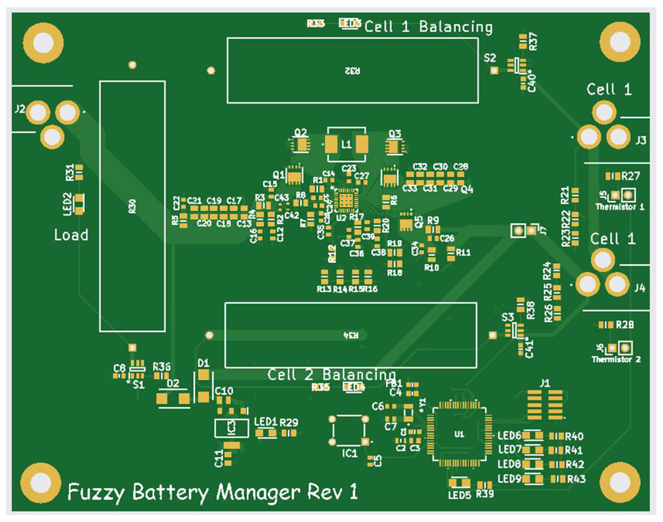
- Hardware-validated system: The fuzzy battery manager transcends theoretical constructs, delivering a system that is rigorously validated in real-world conditions. This validation assures stakeholders of its reliable performance, positioning it as a groundbreaking step forward in practical battery management applications.
- Seamless integration with charging ICs: Utilizing a state-of-the-art ARM M core microcontroller, the system efficiently orchestrates charging and balancing operations. This integration highlights the solution’s adaptability and real-world practicality, ensuring seamless operation across diverse hardware configurations.
- Innovative modifiable membership functions: The system’s standout ability to dynamically adjust charging parameters for different battery chemistries through customizable membership functions represents a paradigm shift in adaptability and safety. Unlike traditional BMSs that necessitate complete system overhauls when switching chemistries [9,10], this approach delivers unparalleled flexibility and ease of adaptability, ensuring optimal operation and safety.
- Comprehensive and cohesive framework: By synthesizing and expanding upon insights from previous studies [8], the fuzzy battery manager offers a comprehensive framework that extends the boundaries of current fuzzy logic applications. This framework not only aligns with established methodologies, but also pushes the envelope further, addressing practical considerations crucial for diverse battery chemistries in contemporary and future realms of BMS technology.
3. The New Proposed System Requirements
- i.
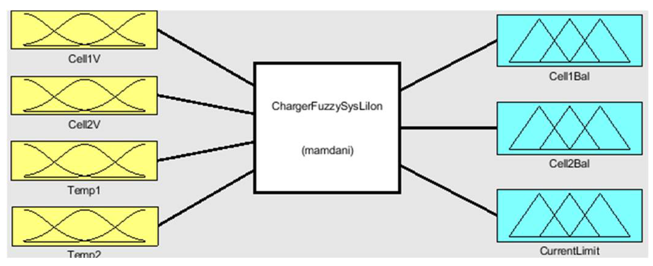
- Implement a fuzzy system that takes current cell voltages and temperatures as inputs and outputs the maximum charging current and control for the balancing circuitry.
- ii.
- Use the results from the fuzzy system to interact with the battery-charging IC and manage the cell balancing circuitry, effectively charging and balancing the battery cells.
- iii.
- The ARM M core microcontroller should control the battery-charging IC, enable a load on the battery, and manage the cell balancing circuitry.
- iv.
- Ensure that the fuzzy system never outputs an unsafe charging current for the battery cells.
- v.
- Demonstrate the real-world functionality of the fuzzy battery manager through hardware implementation.
4. The New Proposed System Design
- i.
- Do not charge cells when one or more cells is at a critically high voltage.
- ii.
- Do not charge cells at a critically high temperature.
- iii.
- Charge very cold cells only with a slow current.
- iv.
- Activate balancing hardware for a cell at critically high voltage.
- v.
- Activate balancing hardware for a cell that has significantly higher voltage than another cell.
- i.
- Charge colder cells with a higher current, except for those too cold to be charged.
- ii.
- Slowly charge cells approaching unsafe high temperatures.
- i.
- Warm up a cold cell by applying a slow charge current and a moderate balancing duty cycle.
- ii.
- Avoid charging or balancing cells that are too hot.
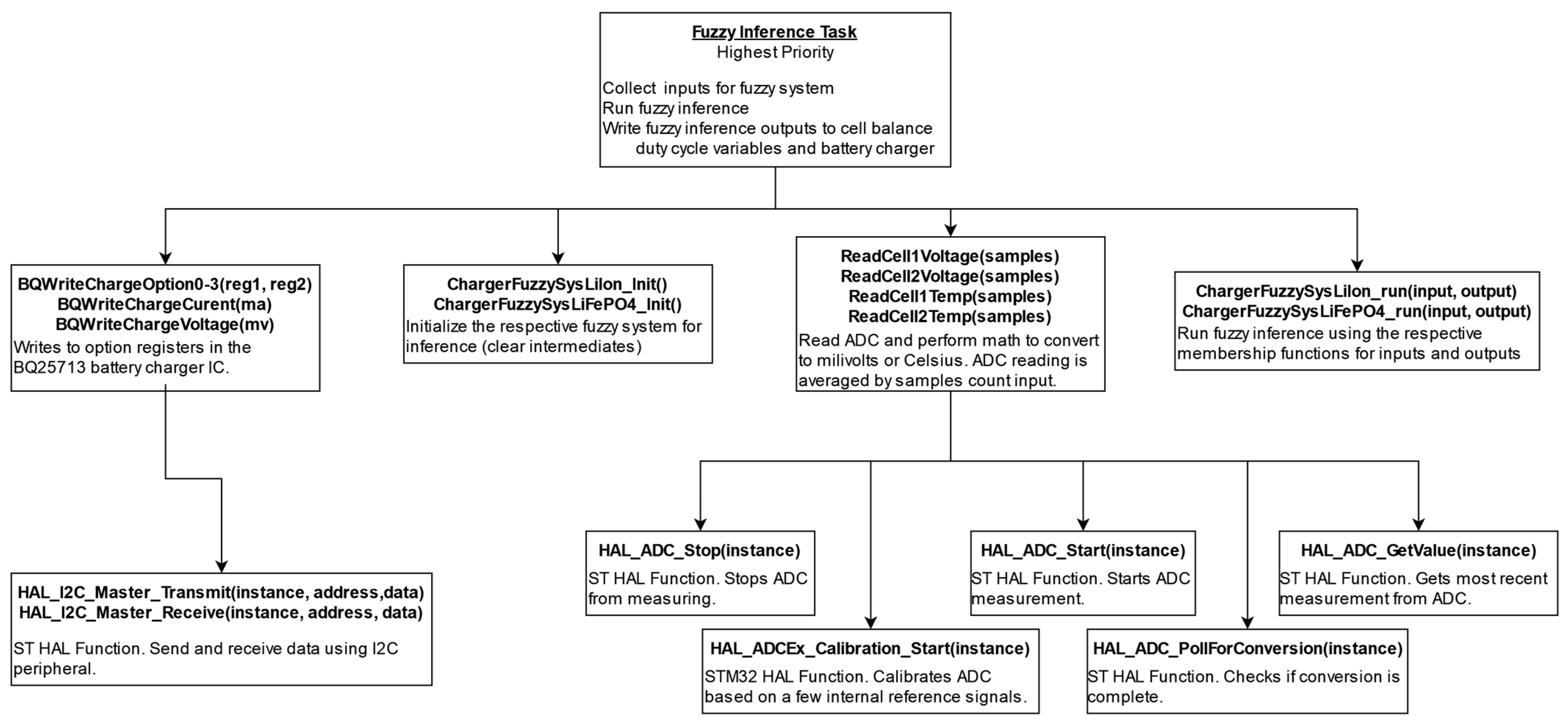
5. The Proposed System Implementation
- Read cell voltages and temperatures:
- °
- Uses four different ADC channels to read each cell’s voltage and temperature.
- °
- Calibrates the ADC channel using ST HAL functions before each measurement.
- °
- Starts the ADC conversion and polls for the result.
- Average ADC results:
- °
- Takes a specified number of samples for each channel to average the readings.
- °
- Averages 100 samples for each of the four inputs.
- Process data with fuzzy inference:
- °
- Places the averaged values into an inputs array.
- °
- Executes fuzzy inference using the ChargerFuzzySysLi* functions.
- Write outputs:
- °
- Updates global variables for the cell balancing task with the calculated duty cycle outputs.
- °
- Sends the current limit output to the battery charger using I2C.
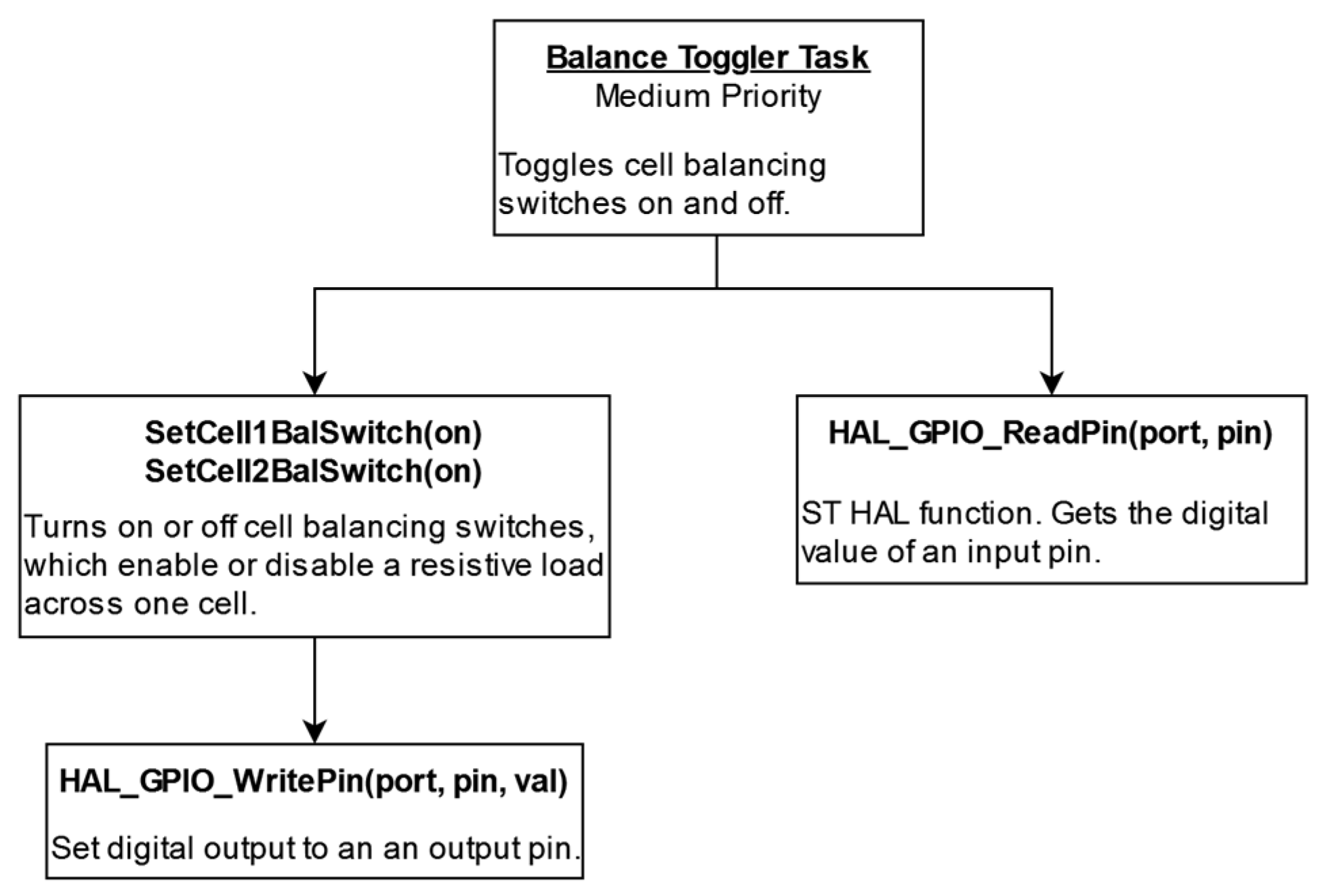
- Duty cycle counter:
- °
- It increments a counter every millisecond until it reaches 1000, then resets it to 0.
- °
- When the counter’s value is below the balancing duty cycle assigned to each cell by the fuzzy inference task, the respective cell’s balancing switch is activated. Otherwise, the switch is deactivated.
- Balancing switch control:
- °
- This control scheme ensures that each cell’s balancing switch operates according to its specific duty cycle using a one-second period.
- “Charge Okay” check:
- °
- The task periodically checks the “charge okay” output from the battery charger.
- °
- Balancing is only enabled if the battery charger is active, avoiding unnecessary balancing when the battery is not charging and not at risk of overcharging.
- Battery voltage assessment:
- °
- It reads the battery voltage measurement obtained from the fuzzy inference task.
- °
- It compares this measurement to specific fractions of the full charge voltage to determine the appropriate charge status.
- Full charge voltage determination:
- °
- The task calculates the full charge voltage by checking the mode switch input.
- °
- This input allows for dynamic switching between battery chemistries, such as Li-Ion and LiFePO4, during operation.
- °
- Depending on the mode switch status, the task references the appropriate charge voltage for comparisons.
6. Results
- current1 = out(3) − v1*0.5*out(1)/4.2;
- current2 = out(3) − v2*0.5*out(2)/4.2;
- v1 = v1 + 0.01*current1;
- v2 = v2 + 0.01*current2;
- t1 = t1 + 0.01*(20-t1) + 0.5*(abs(current1));
- t2 = t2 + 0.01*(20-t2) + 0.5*(abs(current2));
- 1.
- Current calculation:
- °
- The current to each cell is calculated by subtracting the impact of the cell balancing coefficient from the current limit.
- 2.
- Model approximations:
- °
- The voltage of each cell is modeled as linearly related to the current, and the temperature increase is also assumed to be linear with current.
- °
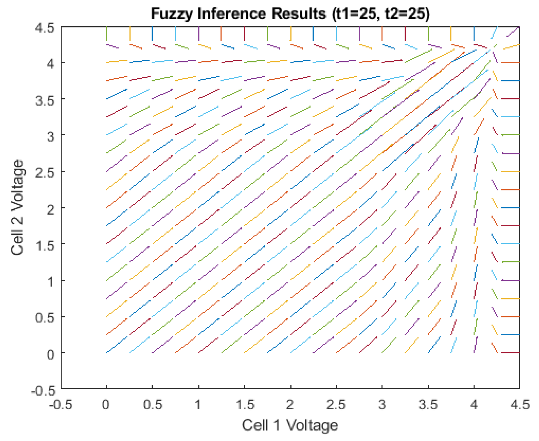
- 3.
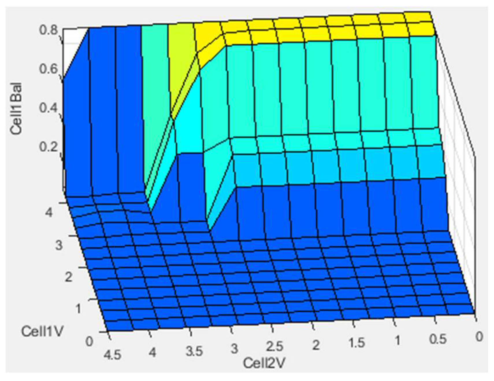
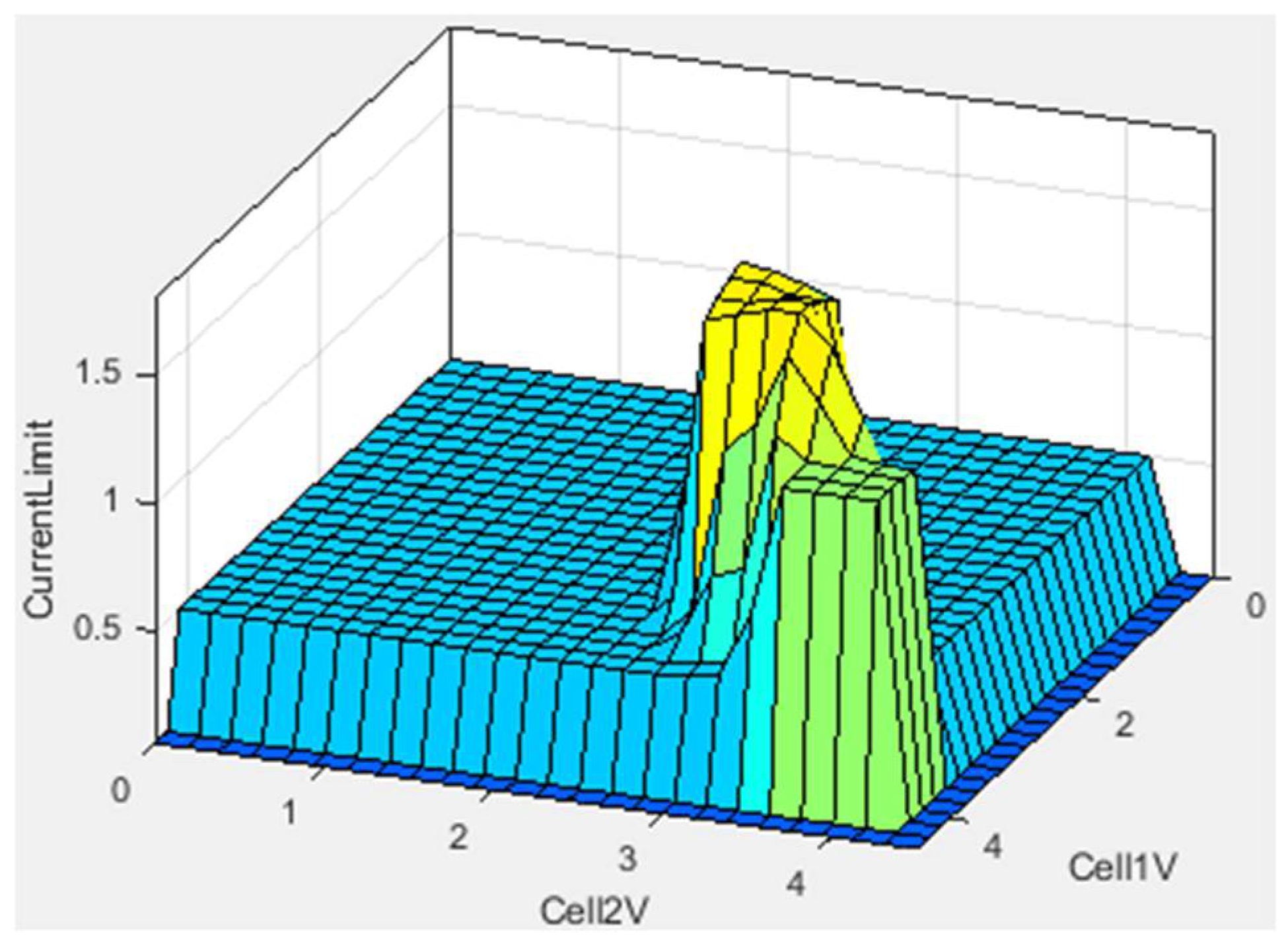
- Fuzzy system reaction visualization:
- °
- By performing fuzzy inference on the outputs from this simplified model and using these as inputs for the fuzzy model, it becomes easier to visualize how the fuzzy system reacts to varying inputs.
- 1.
- Voltage regulation:
- °
- Regardless of the initial voltages, the fuzzy system consistently ensures that no cell exceeds 4.2 V, which is the maximum charge voltage for Li-Ion batteries.
- 2.
- Convergence to full charge:
- °
- The system consistently trends towards achieving a full charge for both cells at 4.2 V.
- Charging or discharging hot cells;
- Discharging cells below the cutoff voltage;
- Charging cold cells with high current;
- Overcharging cells.
7. Discussion
8. Conclusions
Author Contributions
Funding
Data Availability Statement
Conflicts of Interest
References
- Ji, G.; He, L.; Wu, T.; Cui, G. The design of fast charging strategy for lithium-ion batteries and intelligent application: A comprehensive review. Appl. Energy 2025, 377, 124538. [Google Scholar] [CrossRef]
- Pérez, J.A.O.; Guerra, R.G.; Hernández, Y.L.; Velázquez, J.E.V.; Martínez, L.A.V. Charge of LiPo Batteries via Switched Saturated Super-Twisting Algorithm. In Proceedings of the 2020 17th International Conference on Electrical Engineering, Computing Science and Automatic Control (CCE), Mexico City, Mexico, 11–13 November 2020; pp. 1–6. [Google Scholar] [CrossRef]
- Magsumbol, J.-A.V.; Rosales, M.A.; Concepcion, R.; Bandala, A.A.; Sybingco, E.; Vicerra, R.R.P. FLi-BMS: A Fuzzy Logic-based Intelligent Battery Management System for Smart Farm. In Proceedings of the 2022 IEEE 14th International Conference on Humanoid, Nanotechnology, Information Technology, Communication and Control, Environment, and Management (HNICEM), Boracay Island, Philippines, 1–4 December 2022; pp. 1–5. [Google Scholar] [CrossRef]
- Marisno, D.; Chin, C.S.; Shan, C.; See, S. Performance of Adaptive Neuro-Fuzzy Inference System State-of-Charge Estimation of Lithium-Ion Batteries for Electric Ship. In Proceedings of the 2023 8th International Conference on Computational Intelligence and Applications (ICCIA), Haikou, China, 23–25 June 2023; pp. 205–209. [Google Scholar] [CrossRef]
- Ananto, P.; Syabani, F.; Indra, W.D.; Wahyunggoro, O.; Cahyadi, A.I. The state of health of Li-Po batteries based on the battery’s parameters and a fuzzy logic system. In Proceedings of the 2013 Joint International Conference on Rural Information & Communication Technology and Electric-Vehicle Technology (rICT & ICeV-T), Bandung, Indonesia, 26–28 November 2013; pp. 1–4. [Google Scholar] [CrossRef]
- Transue, T.; Maldonado, A.; Santre, T. Fuzzy Inference System for Large Scale Lithium-Ion Battery Management Systems. In Proceedings of the 2019 IEEE Green Technologies Conference (GreenTech), Lafayette, LA, USA, 3–6 April 2019; pp. 1–5. [Google Scholar] [CrossRef]
- Bashir, H.; Yaqoob, A.; Kousar, F.; Khalid, W.; Akhtar, S.; Sultan, W. A Comprehensive Review of Li-ion Battery Cell Balancing Techniques & Implementation of Adaptive Passive Cell Balancing. In Proceedings of the 2022 International Conference on Electrical Engineering and Sustainable Technologies (ICEEST), Lahore, Pakistan, 14–15 December 2022; pp. 1–6. [Google Scholar]
- Joshi, B.; Maherchandani, J.K.; Chhipa, A.A. Comparison Between Open and Closed Loop Battery Charging Technique for Lithium-ion Battery. In Proceedings of the 2021 7th International Conference on Electrical Energy Systems (ICEES), Chennai, India, 11–13 February 2021; pp. 150–155. [Google Scholar]
- Plett, G. Battery Management Systems, Volume I: Battery Modeling; Artech: Boston, MA, USA, 2015; p. 37. [Google Scholar]
- Vermeer, W.; Stecca, M.; Mouli, G.R.C.; Bauer, P. A Critical Review on The Effects of Pulse Charging of Li-ion Batteries. In Proceedings of the 2021 IEEE 19th International Power Electronics and Motion Control Conference (PEMC), Gliwice, Poland, 25–29 April 2021; pp. 217–224. [Google Scholar]
- Bayrak, Z.U.; Kaya, M.N. Modeling and Detailed Analysis of Rule Based, Conventional Fuzzy and Type-II Fuzzy Logic Energy Management Systems of Fuel Cell-Battery Hybrid Powered Unmanned Aerial Vehicles. IEEE Access 2024, 12, 110655–110670. [Google Scholar] [CrossRef]
- Rostami, S.M.R.; Al-Shibaany, Z. Intelligent Energy Management for Full-Active Hybrid Energy Storage Systems in Electric Vehicles Using Teaching–Learning-Based Optimization in Fuzzy Logic Algorithms. IEEE Access 2024, 12, 67665–67680. [Google Scholar] [CrossRef]
- Suhail, M.; Akhtar, I.; Kirmani, S.; Jameel, M. Development of Progressive Fuzzy Logic and ANFIS Control for Energy Management of Plug-In Hybrid Electric Vehicle. IEEE Access 2021, 9, 62219–62231. [Google Scholar] [CrossRef]
- Maghfiroh, H.; Wahyunggoro, O.; Cahyadi, A.I. Energy Management in Hybrid Electric and Hybrid Energy Storage System Vehicles: A Fuzzy Logic Controller Review. IEEE Access 2024, 12, 56097–56109. [Google Scholar] [CrossRef]
- Malele, R.H.; Mendu, B.; Monchusi, B.B. Microcontroller-Driven Battery Management in Hybrid Energy Systems: A Systematic Review of Applications, Control Strategies, and Emerging Trends. IEEE Access 2025, 13, 29341–29360. [Google Scholar] [CrossRef]
- Guler, N.; Ismail, Z.M.; Hazem, Z.B.; Naik, N. Adaptive Fuzzy Logic Controller-Based Intelligent Energy Management System Scheme for Hybrid Electric Vehicles. IEEE Access 2024, 12, 173441–173454. [Google Scholar] [CrossRef]
- Fan, A.; Li, Y.; Fang, S.; Li, Y.; Qiu, H. Energy Management Strategies and Comprehensive Evaluation of Parallel Hybrid Ship Based on Improved Fuzzy Logic Control. IEEE Trans. Transp. Electrif. 2024, 10, 7651–7666. [Google Scholar] [CrossRef]
- Abdelaal, S.; Mukhopadhyay, S.; Rehman, H. Battery Energy Management Techniques for an Electric Vehicle Traction System. IEEE Access 2022, 10, 84015–84037. [Google Scholar] [CrossRef]
- Wang, J.; Zhou, Y. Energy Management of Plug-In Hybrid Electric Vehicles for Autonomous Driving in a Following Environment Based on Fuzzy Adaptive PID Control. IEEE Access 2024, 12, 183832–183850. [Google Scholar] [CrossRef]
- Gautier, M.; Berder, O. Adapting Quality of Service of Energy-Harvesting IoT Devices. In Intelligent Security Management and Control in the IoT; Wiley: Hoboken, NJ, USA, 2022; pp. 133–162. [Google Scholar] [CrossRef]
- INR18650P28A-V1-80093, INR-18650-P28A, Molicel. [Online]. Available online: https://www.molicel.com/wp-content/uploads/INR18650P28A-V1-80093.pdf (accessed on 6 February 2025).
- HeadWay-WI-RD-04, HW 38120HP, Headway. [Online]. Available online: https://www.servovision.com/Battery/Life/Life/HeadWAY38120HP(8Ah)%20LiFePo4%20%20%20Specification.pdf (accessed on 6 February 2025).
- Maiorino, A.; Cilenti, C.; Petruzziello, F.; Aprea, C. A review on thermal management of battery packs for electric vehicles. Appl. Therm. Eng. 2024, 238, 122035. [Google Scholar] [CrossRef]
- Doxygen Awesome. Github.io. 2024. Available online: https://kmilo17pet.github.io/qlibs/qfis_desc.html (accessed on 6 February 2025).
- Cadavid, J. qfiscgen (Fuzzy C-Code Generator for Embedded Systems). Matlab Central File Exchange. 13 September 2022. Available online: https://www.mathworks.com/matlabcentral/fileexchange/117465-qfiscgen-fuzzy-c-code-generator-for-embedded-systems (accessed on 6 February 2025).


| Rule Number | Rule |
|---|---|
| 1 | If (Cell1V is CritHigh) and (Temp1 is not High) then (Cell1Bal is HighBal)(Cell2Bal is None)(CurrentLimit is NoCharge)(1) |
| 2 | If (Cell2V is CritHigh) and (Temp2 is not High) then (Cell1Bal is None)(Cell2Bal is HighBal)(CurrentLimit is NoCharge)(1) |
| 3 | If (Cell1V is High) and (Cell2V is Low) and (Temp1 is not High) then (Cell1Bal is HighBal)(Cell2Bal is None)(1) |
| 4 | If (Cell1V is Low) and (Cell2V is High) and (Temp2 is not High) then (Cell1Bal is None)(Cell2Bal is HighBal)(1) |
| 5 | If (Cell1V is Low) and (Cell2V is Low) then (Cell1Bal is None)(Cell2Bal is None)(1) |
| 6 | If (Cell1V is CritLow) and (Cell2V is CritLow) then (Cell1Bal is None)(Cell2Bal is None)(1) |
| 7 | If (Cell1V is Medium) and (Cell2V is Medium) then (Cell1Bal is None)(Cell2Bal is None)(1) |
| 8 | If (Cell1V is High) and (Cell2V is High) then (Cell1Bal is None)(Cell2Bal is None)(1) |
| 9 | If (Cell1V is CritLow) then (Cell1Bal is None)(1) |
| 10 | If (Cell1V is CritLow) then (Cell2Bal is None)(1) |
| 11 | If (Cell1V is High) and (Cell2V is CritLow) and (Temp1 is not High) then (Cell1Bal is HighBal)(Cell2Bal is None)(1) |
| 12 | If (Cell1V is CritLow) and (Cell2V is High) and (Temp1 is not High) then (Cell1Bal is None)(Cell2Bal is HighBal)(1) |
| 13 | If (Cell1V is Medium) and (Cell2V is Low) then (Cell1Bal is None)(Cell2Bal is None)(1) |
| 14 | If (Cell1V is Low) and (Cell2V is Medium) then (Cell1Bal is None)(Cell2Bal is None)(1) |
| 15 | If (Cell1V is High) and (Cell2V is Medium) then (Cell1Bal is SlowBaL)(Cell2Bal is None)(1) |
| 16 | If (Cell1V is Medium) and (Cell2V is High) then (Cell1Bal is None)(Cell2Bal is SlowBal)(1) |
| 17 | If (Temp1 is High) then (Cell1Bal is None)(1) |
| 18 | If (Temp2 is High) then (CellBal is None)(1) |
| 19 | If (Cell1V is not CritHigh) and (Temp1 is Low) then (Cell1Bal is SlowBal)(1) |
| 20 | If (Cell2V is not CritHigh) and (Temp2 is Slow) then (CellBal is SlowBal)(1) |
| 21 | If (Cell1V is CritLow) and (Cell2V is not CritHgih) and (Temp1 is not High) and (Temp2 is not High) then (CurrentLimit is SlowCharge)(1) |
| 22 | If (Cell1V is not CritHigh) and (Cell2V is CritLow) and (Temp1 is not High) and (Temp2 is not High) then (CurrentLimit is SlowCharge)(1) |
| 23 | If (Cell1V is Low) and (Cell2V is Low and (Temp1 is not High) and (Temp2 is not High) then (CurrentLimit is FastCharge)(1) |
| 24 | If (Cell1V is CritHigh) and (Cell2V is CritHgih) then (CurrentLimit is NoCharge)(1) |
| 25 | If (Cell1V is Medium) and (Cell2V is Medium) and (Temp1 is Medium) and (Temp2 is Medium) then (CurrentLimt is FastCharge)(1) |
| 26 | If (Cell1V is High) and (Cell2V is High) and (Temp1 is Medium) and (Temp2 is Medium) then (CurrentLimt is MediumCharge)(1) |
| 27 | If (Cell1V is High) and (Cell2V is Medium) and (Temp1 is not High) and (Temp2 is not High) then (CurrentLimt is MediumCharge)(0.01) |
| 28 | If (Cell1V is Medium) and (Cell2V is High) and (Temp1 is not High) and (Temp2 is not High) then (CurrentLimt is SlowCharge)(0.01) |
| 29 | If (Cell1V is Low) and (Cell2V is High) and (Temp1 is not High) and (Temp2 is not High) then (CurrentLimt is SlowCharge)(1) |
| 30 | If (Cell1V is High) and (Cell2V is Low) and (Temp1 is not High) and (Temp2 is not High) then (CurrentLimt is SlowCharge)(1) |
| 31 | If (Cell1V is not CritHgih) and (Cell2V is not CritHigh) and (Temp1 is Low) and (Temp2 is not Hgih) then (CurrentLimt is SlowCharge)(1) |
| 32 | If (Temp1 is High) then (CurrentLimit is NoCharge)(1) |
| 33 | If (Temp2 is High) then (CurrentLimit is NoCharge)(1) |
| 34 | If (Cell1V is not CritHgih) and (Cell2V is not CritHigh) and (Temp1 is not Hgih) and (Temp2 is Low) then (CurrentLimt is SlowCharge)(1) |
| 35 | If (Cell1V is not CritHgih) and (Cell2V is High) and (Temp1 is Medium) then (Cell2Bal is HighBal)(1) |
| 36 | If (Cell1V is Hgih) and (Cell2V is CritLow) and (Temp1 is Medium) then (Cell2Bal is HighBal)(1) |
| 37 | If (Cell1V is CritLow) and (Cell2V is Medium) and (Temp1 is Medium) then (Cell1Bal is None)(1) |
| 38 | If (Cell1V is Medium) and (Cell2V is CritLow) and (Temp2 is Medium) then (Cell1Bal is None)(1) |
| 39 | If (Cell1V is CritHigh) and (Cell2V is High) and (Temp2 is not Low) then (Cell2Bal is None)(1) |
| 40 | If (Cell1V is Hgih) and (Cell2V is CritHgih) and (Temp1 is not Low) then (Cell1Bal is None)(1) |
| 41 | If (Cell1V is Low) and (Cell2V is CritLow) and (Temp1 is not Low) then (Cell1Bal is None)(1) |
| 42 | If (Cell1V is CritLow) and (Cell2V is Low) and (Temp2 is not Low) then (Cell2Bal is None)(1) |
| 43 | If (Cell1V is Medium) and (Cell2V is CritLow) and (Temp1 is Medium) then (Cell1Bal is SlowBal)(1) |
| 44 | If (Cell1V is CritLow) and (Cell2V is Medium) and (Temp2 is Medium) then (Cell1Bal is SlowBal)(1) |
Disclaimer/Publisher’s Note: The statements, opinions and data contained in all publications are solely those of the individual author(s) and contributor(s) and not of MDPI and/or the editor(s). MDPI and/or the editor(s) disclaim responsibility for any injury to people or property resulting from any ideas, methods, instructions or products referred to in the content. |
© 2025 by the authors. Licensee MDPI, Basel, Switzerland. This article is an open access article distributed under the terms and conditions of the Creative Commons Attribution (CC BY) license (https://creativecommons.org/licenses/by/4.0/).
Share and Cite
Shaout, A.K.; Brauchler, Z. Fuzzy Battery Manager: Charging and Balancing Rechargeable Battery Cells with Fuzzy Logic. Electronics 2025, 14, 1470. https://doi.org/10.3390/electronics14071470
Shaout AK, Brauchler Z. Fuzzy Battery Manager: Charging and Balancing Rechargeable Battery Cells with Fuzzy Logic. Electronics. 2025; 14(7):1470. https://doi.org/10.3390/electronics14071470
Chicago/Turabian StyleShaout, Adnan K., and Zachary Brauchler. 2025. "Fuzzy Battery Manager: Charging and Balancing Rechargeable Battery Cells with Fuzzy Logic" Electronics 14, no. 7: 1470. https://doi.org/10.3390/electronics14071470
APA StyleShaout, A. K., & Brauchler, Z. (2025). Fuzzy Battery Manager: Charging and Balancing Rechargeable Battery Cells with Fuzzy Logic. Electronics, 14(7), 1470. https://doi.org/10.3390/electronics14071470