1. Introduction
Radio Frequency Identification (RFID) is one of the most preferred auto-ID technologies among bar code, QR code etc. The word RFID illustrates that object is to be identified by transferring electromagnetic waves. Identification, monitoring and authentication are the significant features of the RFID. A variety of industries have applied RFID technology, from health department to inventory management to industry [
1]. This phenomenon is also rapidly implementing to vehicle management over the decade. Parking lot, speed monitoring to electronic toll gate RFID is efficiently employed. Electronic toll collection (ETC) is one of the busiest and most economically beneficial sectors of vehicle transportation. Around the world, RFID is used in almost all ETC. Currently, there is a lane system where each lane has its own reader antenna and tolling booth. The system is therefore expensive to install since each reader has to be paired with a tolling booth. Each lane permits one car to pass the gate at a time hence there is delay to proceed the whole operation.
Therefore, there must have a suitable model of ETC that operates fast and effortlessly at low cost.
Figure 1 depicted the outline of the suggested model considering required parameters and corresponding possible issues.
The proposed scenario for ETC is designed in such a way that two reader antennas (no. of antenna can be varied according to the toll gate area) installed at the top of the toll gate. The first and foremost concern is that total number of reader antennas can cover the total gate area. A variety of factors influence the installation mechanism, such as the height of the antenna position, the inclination angle, and the beamwidth. The red colored triangle and circle shape represent the possible issues. The tringle one depicts the reader collision, while two reader antennas are try to read the same tag attached on vehicle. The circle one represents the tag collision, when multiple vehicle respond to the same reader. Corresponding solutions are suggested to mitigate the problems. Modified pulse protocol is proposed for reader collision and M-ry tree algorithm for tag collision.
The position of the reader antenna needs to account the variables such height, downtilt angle, and beamwidth to reduce the path loss and increase the signal strength. Two ray model is the best way to determine the signal strength [
2,
3,
4]. Downtilt angle and beamwidth are required for maximize the coverage area [
5,
6]. More than one reader antenna within operating region leads to reader collision. RFID functioning is affected in terms of inaccurate and slow readings due to this collisions. To prevent collisions, two mechanisms have been investigated: centralized and distributed. In the centralized method, a central server is responsible for synchronizing all readers and sharing resources. By using the distributed method, readers trade the required information directly to each other without the intervention of a central server [
7]. The two methods are based on different protocols, such as the Class 1 Generation 2 UHF standard, Colorwave, and ETSI EN 302 208 [
8,
9].
On the other side, responding multiple tags at the same time creates tag collision leads to inaccurate vehicle identification. ALOHA-based and tree-based algorithms are used to prevent tag collisions [
10].
2. Related Work
There is no research done yet to propose a complete model of RFID implementation in vehicle management at toll gate with no-lane concept. The proposed model has three parts: antenna installation, algorithms to avoid reader collision as well as tag collision. Contemporary research is considered and discussed here that can highlight the work done on each part distinctively.
In [
2], two ray model is used to investigate path loss effect of RFID system at different heights. Multi ray model is designed for line of sight communication (LoS) communication at mm wave frequency [
4]. Frequency diversity is introduced in two ray propagation model for indoor and outdoor environment [
3]. In [
11], research revealed that when down tilting mechanism is used, a vertical beam focuses on the vehicle on the road and reduces interference outside of the beam. It is necessary to determine the downtilt angle of the antenna element in order to maximize the coverage range of the reader antenna. Mechanical downtilt angle (MDT) and electrical downtilt angle (EDT) are two common approaches. For mechanical methods, a site visit is necessary to calibrate the tilt angle. The electrical method, on the other hand, does not require site visit, but requires a control system and advanced technology to adjust the tilt angle when necessary [
12]. As a result, MDT is the preferred method for simplicity and low cost.
Thereafter, to mitigate reader collision multi-access methods are used which include frequency division multiple access (FDMA), time division multiple access (TDMA), code division multiple access (CDMA), and carrier sense multiple access (CSMA) [
13,
14,
15]. In Class 1 Generation 2 UHF standard, FDMA uses two separate frequency channels to establish communication with tags [
16]. Although this method reduces interference between readers, reader-to-tag collisions remain a problem. Furthermore, conventional passive tags do not have any on-board frequency tunning circuit, so they cannot identify specific readers of corresponding frequency channels. TDMA based Colorwave provides different time slots to interfering readers to avoid simultaneous transmission [
17]. Each reader selects a different time slot or color to transmit. In the event that any adjacent reader chooses the same time slot, it reselects a new time slot. It is crucial for this method to ensure accurate time synchronization between participants. In CDMA, all tags must be code-designated and need extra on-board circuit, which makes the system complicated and expensive [
16,
17]. ETSI EN 302 208 is one of the most advanced protocols for RFID applications. CSMA mechanism called ‘Listen before Talk’ is used in the above protocol. If the data channel is idle, the reader starts reading if it is not, it waits for random backoff time [
13,
18].
Another distributed method, pulse protocol used for passive tags and the method can be made cost-effective. Pulse protocol uses two independent channels. The first is a control channel, and the second is a data channel. For reader-tag communication, a data channel is used. An investigation of the reader’s action is conducted through the control channel [
19,
20]. As the number of readers increases, collisions persist.
Next, tag collision is reduced by probabilistic or deterministic approach. ALOHA based algorithms could reduce tag collisions but may take a long time to identify the tag, resulting in tag deprivation [
10,
21]. The tree algorithm is a deterministic approach to receiving tag responses. By enquiring with the identifying number in the read cycle, the reader validates tags in the interrogation zone. There are three types of tree algorithms including collision tree, query tree, and binary tree [
10].
A query tree protocol enquires with a series of prefixes. Tag compares the prefix with the tag ID and if the comparison is true, tag responds with the tag ID. A collision mode reader sends a 1-bit prefix query and splits the group into two subgroups. As a result, one subgroup sends the ID to the reader while another subgroup waits for the next query. The reader keeps splitting the group until all tags have been identified [
22].
The bit tracking algorithm is a binary procedure. Manchester code is used to detect collided bits. A Manchester code expresses bit utility by following the change in level at transitions [
23,
24].
A collision tree combines binary trees and query trees by splitting tags into groups and generating a new prefix for the collided tags [
25]. Identifying trees and resolving idle cycles are the main challenges of these protocols.
2.1. Comparison with Related Work
In literature, most research has been focused on individual RFID system challenges such as antenna deployment, reader collisions, or tag collisions. All these challenges have been addressed and resolved in our research work. The proposed two-ray solution provides the optimization of antenna height and signal strength accounting the reflection coefficient of the ground path. In outdoor environment, concrete road is considered to determine the received power. Distributed algorithm, Pulse protocol is modified further to reduce reader collision probability and provide equal opportunity to all readers. Query tree is suggested with M-elements and trimming method is also applied to omit the idle nodes for enhancing the identification time of tag.
Antenna propagation model: Comparing the received signal strength, refs. [
2,
3,
4] investigated on general wireless communication model, where, our proposal is for real application of RFID toll system. Instead of approaching multipath propagation like [
4] our approach is simple ground reflection phenomenon considering real concrete road having fundamental computational process. Our approach is cost effective on a larger scale as it has not included frequency diversity like [
3]. Furthermore, we have estimated the antenna installation specification such as height and downtilt angle.
Reader Collision: Unlike [
13], our approach does not need a time slot allocation and can avoid delay in identification speed. There are no messaging scheme between readers in our protocol like [
15] which leads to add extra communication system. Sharing information of neighboring reader’s signal strength may cause congestion in [
16]. Waiting time interval and probability distribution function of contention window are improved than [
20] to reduce collision and fair chance to each reader to communicate with tag.
Tag collision: The prime challenge of [
21,
22] is to handle large number of tags as the identification method is slot based. In [
21], tags are pre-defined correlated ID’s therefore, if tag ID’s are assigned randomly such as vehicle management deployment, efficiency of the algorithm is reduced. In the same manner if ID distribution is not uniform collision may still occur in [
10]. Our algorithm is scalable for large number of tags. In [
23], multiple tag respond in same slot, increases complexity. In our approach each tag respond when query occurs, reducing interferences. In a real application such as ETC, where large number of random vehicle needed to manage, our approach is more reliable and efficient.
2.2. Motivation of the Proposed Work
The existing ETC model is lane based. Single reader antenna is installed in each lane along with toll booth and system. Vehicles need to stand in queue to pass the toll gate. The following limitations are remain there:
Installation and maintenance cost: Installing each reader antenna and maintaining them with system software made the system expensive. Further, it required man power for each booth to operate the system.
Throughput and delay: One vehicle at a time creates traffic, cause delay and reduction of the system throughput.
Anti-collision algorithm: Suitable anti-collision algorithm is required to identify all the vehicles within less time and without any error.
2.3. Key Contributions
This paper introduces a complete model to reshape the existing ETC structure. It suggested that placement of two reader antenna at a particular height and proper angle is adequate to cover the toll gate area. This way it offers a cost effective, low latency and higher throughput system. It also identified the challenges such as possible reader collision, tag collision and provided required solution. A three-fold solution is proposed based on these objectives:
Two-ray model: The installation of the reader antenna makes sure the maximum signal strength to detect vehicle. The concrete road is accounted for the ground’s reflection coefficient when determining the reader antenna’s position. This method helps determine the optimal antenna height and downtilt angle for optimizing signal strength.
Modified pulse protocol: A triangular distribution function for the contention window is implemented in the Modified Pulse Protocol algorithm to identify the reader collision challenges and enhance the efficiency of the conventional pulse protocol.
M-ary Trimming Query tree: To resolve tag collisions for managing the framework that involved multiple tagged vehicles, the M-ary Trimming Query tree algorithm is introduced. An improved tree-splitting method is improvised with a clipping principle to reduce idle node times, emerge low tag identification times, and increase system efficiency.
Using modified algorithms, we have developed a intrgated model for RFID antenna deployment that includes solutions for reader-tag collisions. In order to verify the analysis and confirm the model’s efficacy, MATLAB version 20.0 is used.
The rest of this paper is organized as follows. In
Section 3, the optimal location of the reader antenna in the Two-ray model is comprehensively discussed. As discussed in
Section 4, the Modified Pulse Protocol algorithm improves the distribution of contention window to mitigate reader collision challenges. By eliminating idle cycles in
Section 5, we are able to construct an M-ary Query tree algorithm that reduces tag collisions and enhances system performance.
Section 6 summarizes all executed results. Practical applicability of the proposed research is discuss in
Section 7. Finally,
Section 8 draws the conclusions.
3. Geometrical Model of Reader Antenna Deployment
According to our proposed model there two or more reader antennas are installed at the toll gate, for simplification we optimized the signal strength of single reader antenna in this section. This is an open unbounded environment with very less probability of having multipath reflection from any scattering object. Therefore, line of sight (LoS) and ground reflection paths are the significant parameters to characterize the propagation model in the reader-tag channel. Hence, two-ray model has been implemented without any loss of generality. Further, both the reader and tag antennas are considered to be polarization matched for the sake of simplicity.
Figure 2 illustrates a geometrical model of reader antenna placement in relation to road based on the two-ray ground reflection phenomenon. An evaluation of the effective signal received by the tag on the car is based on the line-of-sight signal (direct wave) from the reader antenna to the car and the reflected wave from the ground. Using Friis’ transmission equation, the power transmitted from the reader to the tag antenna is given as follows [
26].
where,
are the transmitted power and gain of the reader antenna, respectively.
is the received power by the tag antenna and
is the gain of the tag antenna, respectively. The distance between reader and tag is
and wavelength of the signal is
. From (1) it is noted that received power is varies with
.
Referring to
Figure 1, the distances of the path travelled by the direct and reflected waves are
d1 and
d2, respectively. These distances are obtained as follow [
3].
where
is the height of the reader antenna from the ground, and
is highest vehicle height.
Considering both the direct and reflected waves, the total received power
is given as follows [
26].
where
is the reflection coefficient of the road which is assumed to be made of asphalt concrete. The value of
can be computed from the following equations [
27].
where
is the wave impedance of the ground and
is the wave impedance of the air.
=
, where
and
are the relative permeability and relative permittivity of the
ith medium and 377 Ω is the impedance of free space. In this scenario,
is taken as unity. The relative permittivity of the Asphaltic concrete material is 3.8 [
28]. Therefore, Equation (4) can be written as follows.
where
.
The path difference between the direct and reflected waves is denoted as
, which is given as follows [
3,
4].
Using Taylor series expansion,
can be written as follows.
As,
the direct wave distance
is nearly equal to total distance
,
. Therefore, Equation (7) can be rewritten as follows.
where
denote the phase difference between the directive wave
) and the reflected wave
Therefore,
Conclusion can be drawn from Equation (14) that the power received by the tag antenna is inversely proportional to the square of the ground distance () and LOS distance () between the reader antenna and vehicle, when reflected component is present.
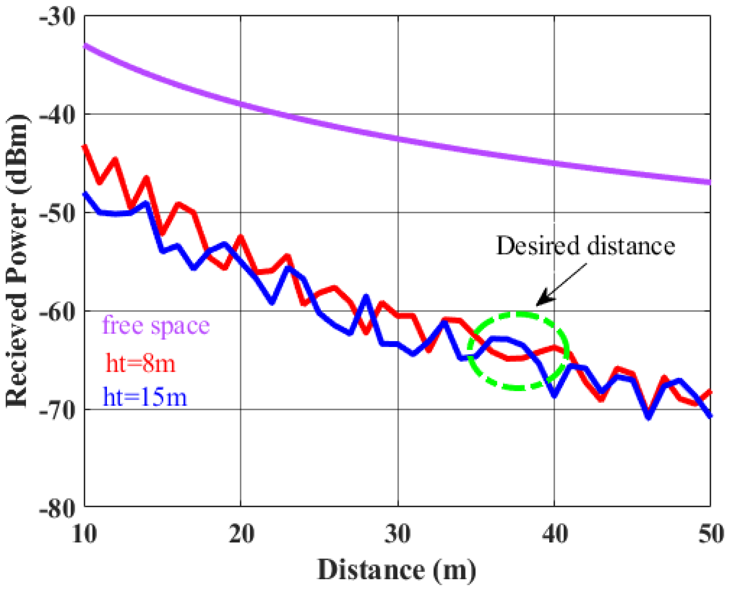
The simulation result of received power by the tag at vehicle as obtained from Equation (14) is graphically presented in
Figure 3. The simulation is examined with two different antenna heights from the ground (
). It is observed that power response of LOS is monotonically decreased over the distance. In two ray response, the simultaneous occurrence of constructive and destructive interference between the direct ray and reflected ray results in a response with a sequence of maxima and minima. Hence, for a chosen distance (
), the preferred height of the reader from the ground is to be determined. For example, if the user wants the tag to be detected at a distance of 35–38 m, then, from
Figure 3, it is demonstrated that a height of 15 m is preferred over the other heights, since at that height, maximum constructive interference is taking place at a distance of 35–38 m thereby delivering maximum power with respect to other heights of the reader antenna.
For RFID reader-to-tag communication, the choice of antenna type plays an important role after determining the appropriate height of the reader antenna (15 m).
This proposed system considers the reader antenna as having a directional radiation pattern and the tag antenna as having an omnidirectional radiation pattern. Mechanical downtilt angle is used to estimate coverage area.
The optimum downtilt angle is needed to maximize the area and capacity. It depends on two key features including geometrical factor (
) and antenna vertical beamwidth
.
is given as follows [
29].
Thereafter, the downtilt angle (θ) is determined from,
Using (15) and (16), the variation of downtilt angle with distance (
) is graphically presented in
Figure 4. The figure exhibits that the downtilt angle should be decreased with increase in horizontal distance from reader to tag (
). Taking the example of
Figure 3, if the distance d is desired to be within 35–38 m, the preferred downtilt angle should be 45.4°.
When Reader antennas are tilted downward, the Half-Power beamwidth of the horizontal radiation pattern is reduced in the central direction, but is increased in the sideways direction [
5,
6].
Figure 5 shows a simulated radiation pattern for a helical reader antenna at various tilt angles. As downtilt angle increases, the gain of the reader antenna decreases and half-power beamwidth (HPBW) increases.
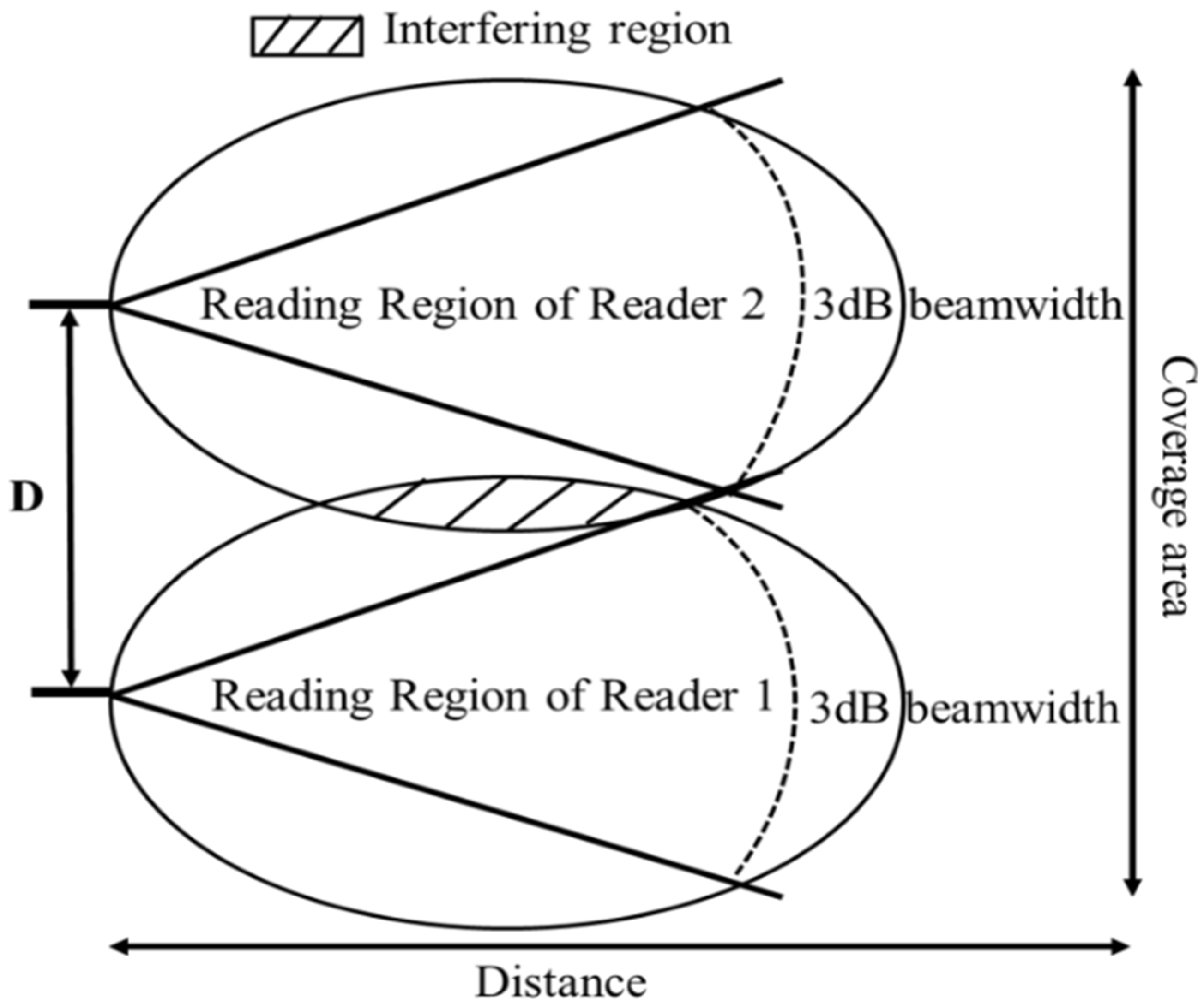
From
Figure 5, we can observe that for the example taken, as the downtilt angle is 45.4°, the corresponding HPBW is considerably larger than that for zero downtilt angle. Accordingly, the deployment of adjacent reader antennas after accurately determining the antenna height from ground and downtilt angle will create an interference zone in the reader-tag communication channel as illustrated in
Figure 6.
4. Reader Collision
In order to avoid reader collisions effectively, pulse protocol can be applied in a more promising manner. By modifying the waiting state of the reader after the reading operation is completed, the proposed pulse protocol differs from the conventional one. If more than one reader initiates the same random backoff time, the probability of collision increases. As a result, in the proposed method, the waiting time is modified in such a way that the probability of a collision between readers is reduced and the probability of reading the tags increases.
A standard pulse protocol reader transmission is shown in
Figure 7a [
19], and a modified pulse protocol reader transmission is shown in
Figure 7b.
Figure 7a illustrates how the reader reads the tag during the time slot as follows: During the period of while communicating with tags, the reader
sends beacon signals to the readers
and
over the control channel. We are unable to read any tags during this time
. For a period of time
after transmission ends, all readers enter a waiting state for a period of
. They will resume their backoff time at the end of the time slot.
The backoff time in is two time slots. A new random backoff time is chosen by , which is also two time slots. At the end of the backoff time slots of and, both attempt to read the tag simultaneously, resulting in reader collisions. As shown in the figure, within the given time frame, due to uniform waiting time for all readers irrespective of whether they have communicated with a tag or not and random selection of backoff time, is not getting a chance to communicate with a tag. Corresponding, algorithm is formulated in terms of modifying waiting time.
As illustrated in
Figure 7b, in the proposed algorithm, instead of having uniform waiting time, the waiting time is expanded after the reading slot of each reader. After
operation of reader
, wait time for
is
instead of
(
>
) whereas for the remaining readers
and
, the wait time remains
. Therefore, while
is still in waiting state,
and
start the residual backoff time. As depicted in the figure, the backoff time of
ends prior to
and
starts to communicate with tag. The cycle repeats and
gets the chance to read tag. Hence, this process minimizes the reader.
Collision probability as well as gives all the readers opportunity to communicate with the tags.
The following algorithm describes the graphical representation of the operation. is the maximum waiting time after successful reading and it is considered as = 3 .
The following assumptions are taken to develop the algorithm:
Consistently all the readers can establish the communication with tag. But, at a specified time, no more than one reader can communicate.
All the readers receive the beacon which implies that there is no hidden reader.
One slot size is equivalent to one time unit with the value of beacon interval ().
The maximum length of the contention window considered as CW. Reader selects random value from the contention window [0, CW]. Contend backoff time is decreased to zero count and then reader starts communication [
20]. In the proposed protocol, the probability distribution of the contention window is considered as monotonically decreasing triangular function. It implies that lesser the backoff time, more is the probability of the reader transmission to tag. The distribution function of the contention window can be expressed mathematically as [
30].
The average of the distribution derives as
Referring to
Figure 7, backoff time is decremented after maximum beacon interval, called Adaptive Beacon Interval (ABI). The maximum adaptive beacon interval of the algorithm is
=
+
+ 1. Correspondingly, during the collision period, readers wait for collision slot and next empty slot. Hence, the duration of ABI is
. Empty period refers to when no collision or successful events take place.
Active ABI is defined when at least one reader communicates. The probability of active ABI is given as [
20],
The probability of successful transmission in ABI duration is given by [
20],
Therefore, the probability of collision event in ABI duration is given as [
20],
The total probability of empty slot and collision slot and successful slot is 1. Therefore,
Average duration of ABI can be obtained from,
The probability of collision of
’s and
’s transmission is
. If there are
number of readers, the probability of collision in
’s transmission is,
If collision with probability of P occurs, reader selects another random backoff value from [0, CW] and transmit again at the end the backoff value. Therefore, according to the geometric distribution, the number of transmission trials can be defined with the probability of success (
). Thus, until the successful transmission happens the expected number of ABI is defined by [
20],
The average duration of reader transmission cycle is given by:
The number of queries is determined by the reader over data channel within
period. The maximum number of beacon intervals is “a”. Therefore,
=
. In each slot of the “a” number of beacon intervals, one beacon is transmitted on the control channel and multiple number of queries on the data channel.
can be calculated for a beacon interval as [
20],
Throughput and utilization describe the system’s merit. The number of successful periods by all readers in one cycle is determined by
. The number of successful queries sent by reader is
. Therefore, total throughput is defined as [
16]
Utilization is obtained from,
The parameters considered in the proposed Algorithm 1 with the corresponding values is tabulated in
Table 1.
| Algorithm 1: Queue Delay Calibration () |
/* Initialize parameters */
r
if State_value = = 1; /* state is idle*/
else if State_value = = 0 && State = “Contend”
while control channel is busy
→ ∆t
end while
while control channel is idle
end while
else if State_value ∉ {0,1} /* state is waiting*/
> 0
≤ 0
r
end while
end if
while control channel is idle
Beacon is transmitting over control channel
State = “Reading”
end while
≤ 0
if State = = “Successful”
cancel all timer
else if State = ”Waiting”
resetting state after reading
end while
end if
end if
end if
end if |
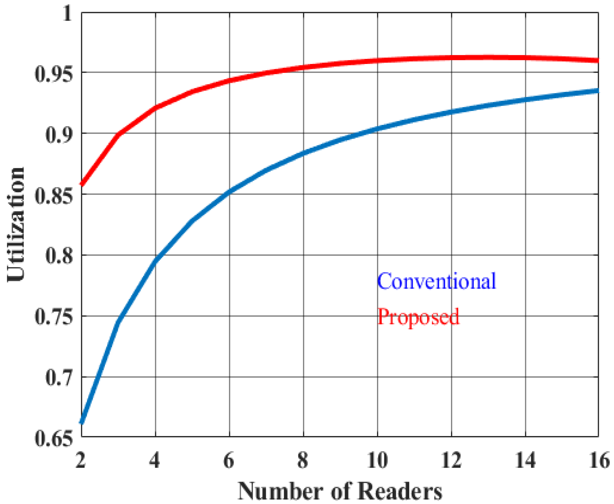
As can be seen in
Figure 8 and
Figure 9, the simulation graph depicts the system’s throughput and utilization.
Figure 8 and
Figure 9 show the responses of the conventional pulse protocol and the modified pulse protocol. When the number of readers is low, the probability of an empty slot is high, and as the number of readers increases, the probability of an empty slot decreases. Therefore, throughput of the system also increases, however large number of readers initiates collision slots. According to the proposed algorithm, the throughput of the system is much higher than conventional one since the average value of contention window and waiting time are modified. With four readers working together in the system, the throughput reached 2165 queries/s for the existing method and 2509 queries/s for the proposed one. As the number of readers increases, communication duration between reader and tag becomes shorter. As a result, the overall utilization of the system reached nearly 92% for the proposed protocol, which is 15.2% higher than the existing protocol.
The execution time analysis is depicted in
Figure 10 to define the computational complexity of the proposed Modified Pulse Protocol.
Three main parameters are considered for determining the computational complexity. (i) Contention window as it determines the average back-off time for each reader. (ii) Collision of probability to notify that how many retransmissions are required. (iii) Adaptive Beacon Interval (ABI) as it supervises the duration cycle. Readers are varied from 1 to 20 and execution time is evaluated for each reader.
It is observed from the
Figure 10 that execution time is increases in a piece-wise linear manner as number of readers are increased. The maximum execution time is 0.008 s for 20 readers. Therefore, the selection of our contention window as triangle distribution function reduced execution time and established computational efficiency.
Further, memory depends primarily on number of readers and execution time. Therefore, proposed algorithm runs within O(n) complexity. That signify linear memory usage.
5. Tag Collision
By modifying the existing Tree-based algorithm, the proposed communication model resolves the tag collision issue. By reducing idle nodes in the tree, the proposed model increases tag identification time very quickly. A schematic of the query-tree is shown in
Figure 11. Based on the tag response, each node in the proposed tree algorithm defines the anti-collision condition. The nodes are categorized into three modes—idle, readable (successful), and collision. These conditions are defined as follows [
23,
31].
Idle: There is no transmission as no tag is present in the query zone.
Readable: Successful transmission as single tag responds to the query of reader.
Collision: Collision occurs as multiple tags respond to the query of the same reader.
Tag collision can be more efficiently reduced if binary query tree is improved to M-ary query tree. The same number of tags can be identified in M-ary tree algorithm with a less collision cycle however, number of idle cycles increases as compared to binary query tree [
22,
32]. Hence, to further reduce the idle cycles without compromising the tag collision probability, the M-ary Trimming Query tree is proposed in this work.
As shown in
Figure 10, an M-ary tree is divided into
groups of bits, highlighted as b
0, b
1 up to b
m−1. The reader first sends query prefix to tag in communicating zone. The tag responds to the query after comparing with the own ID prefix. Collision bit detection is carried out by Manchester code. If there is collision, reader updates the query prefix and collision node is divided further in the next level into M-groups as illustrated in
Figure 10.
The trimming for the M-ary tree method is carried out in three ways. Consider the value of is 8 and the position of the highest collided bit bm−1 is 0, then all query nodes with a least significant bit (LSB) value 1 are eliminated and rest of nodes are set as new prefix and added to stack. Inversely, if the the highest collided bit bm−1 is 1, then query nodes with LSB value 0 are removed and rest of the nodes are set as new prefix and pushed to stack. If the highest collided bit is unknown then there will be no trimming, it will get forwarded to the subsequent level of the tree.
The key parameter of RFID tag identification is total time slot. In an anticollision algorithm, lesser the total time slot, greater the speed of execution of the algorithm. The analytical calculation is compared between conventional M-ary tree and M-ary trimming tree. Root node, intermediate nodes and leaf nodes are the sections of the M-ary query trimming tree. The level of leaf node is zero and level of intermediate node is equal to level of the tree e.g.,
. Therefore, total nodes of the M-ary tree is [
33]:
where,
is the number of nodes at level 0 and
is the number of nodes at level
M. The root node is not the child node. Intermediate node has
number of children nodes and leaf nodes don’t have any child node. Thus, total number of nodes of M-ary tree is [
33]
Hence, number of leaf nodes and intermediate nodes can be determined as,
Let,
is the number of tags. The number of leaf nodes is equal to number of tags, which are needed to be identified under the trimming condition as there is no idle slot in this algorithm. Therefore,
Let, at the trimming condition, the probability of getting least collision at the intermediate node is 1. Therefore, new intermediate node (
) at level
becomes
Then time slot (
) is,
There are possibilities to have
number of idle nodes in a tree and the remaining one is the collision node. Let,
is the readable node and
is the leaf node or idle node. Therefore, time slot (
) without trimming condition is also evaluated as,
The M-array trimming tree initiated the total time slot (T) of the algorithm after cutting off the idle node is [
33]
The ratio between the total number of identified tag and required total identification time is defined as throughput of the identification. The efficiency of the algorithm is defined by the throughput (
) [
33]. Therefore,
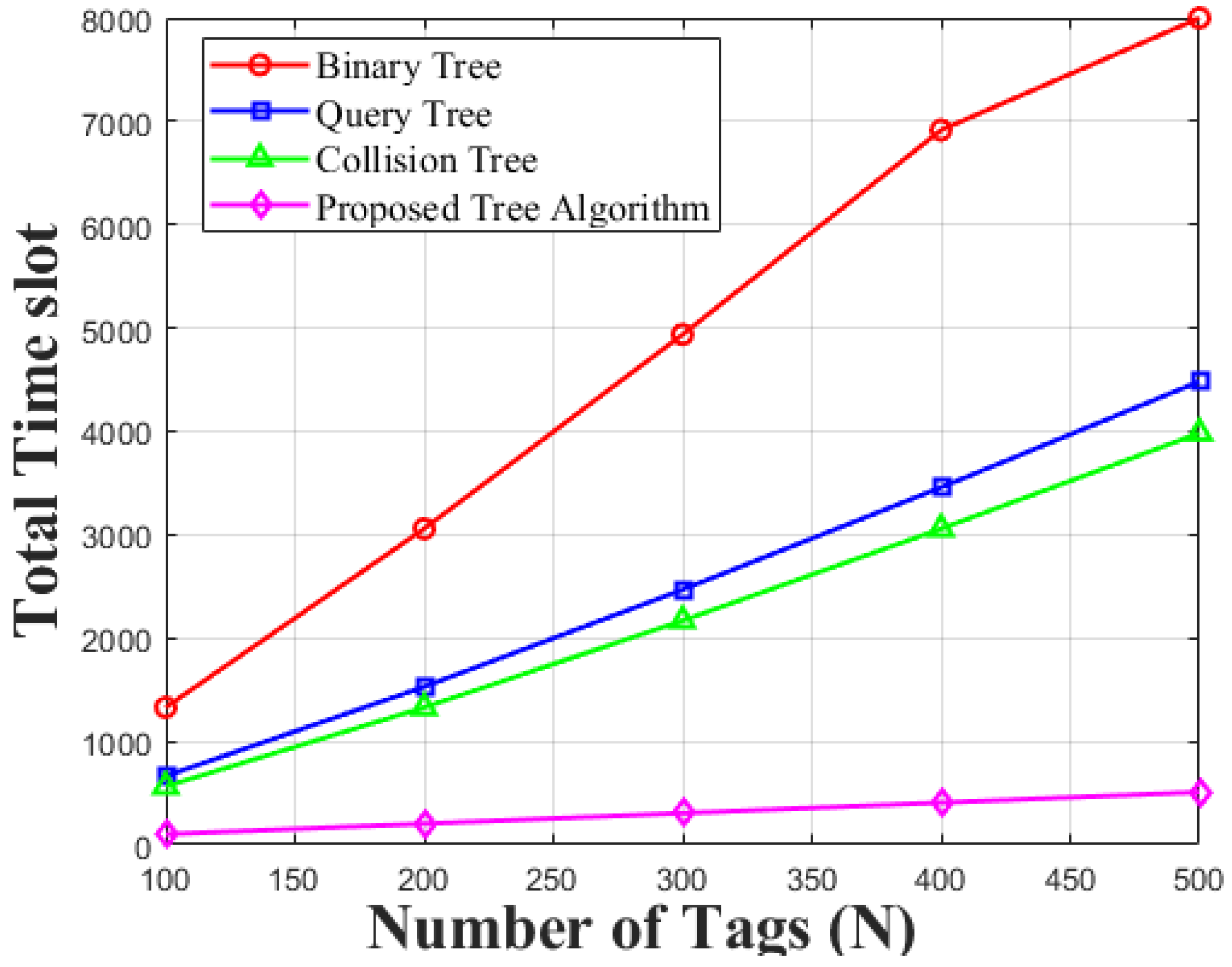
Figure 12 depicts the comparison between conventional M-ary query tree and proposed M-ary Trimming Query tree by using the values of
. It is observed from the figure that, for any value of
, the total time slot is reduced in proposed algorithm as it eliminates the idle slots. The figure also shows that as the value of M-arry tree increases the total time slot for tag detection decreases.
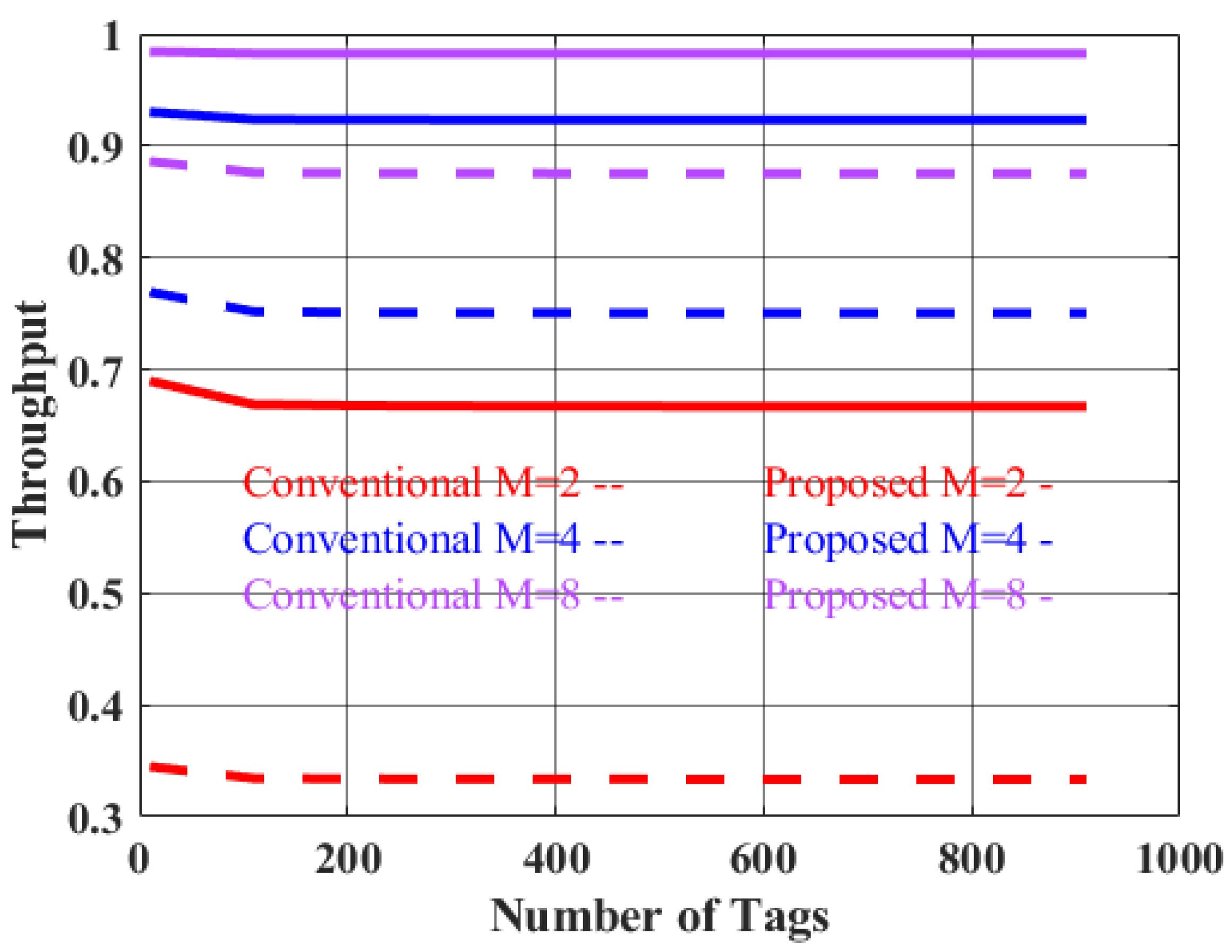
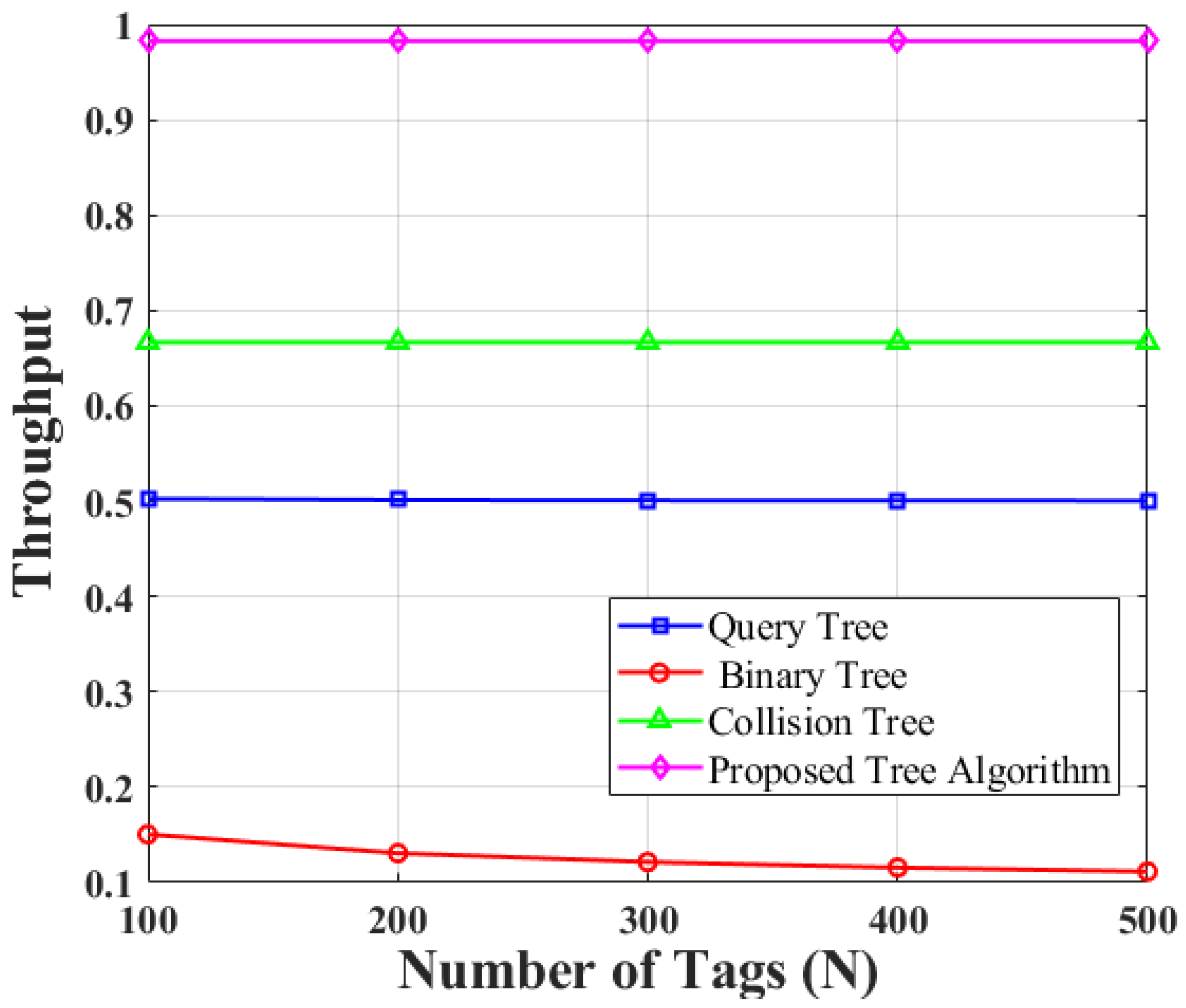
Figure 13 depicted the results of system throughput for conventional and proposed algorithm with accounting different
values such as (
). It is clearly seen from the respond that as the element of the tree is increased the identification time is decreased and therefore throughput of the maximum value of (
) tree with trimming capability reached nearly 98% which is 11.8% higher than conventional one with same
value.
To implement the proposed algorithm in real-world application, a middleware or firmware customized RFID reader is needed to communicate with tags. The algorithm can be written within readers software stack through API programming. Tag identification time and responses will register into computer interface. Every time it will record the tag responses and expand the query if tag responses. If there is no response from query branch, it will trim and not query further. This way it will save the query time and enhance the identification time.

 ,
, 


