


Robust DC Grid Voltage Support in a Single-Stage PV Converter

Abstract
1. Introduction
- Static and Dynamic Grid Support: The controller offers both static and dynamic voltage support, improving overall grid stability in grid-connected PV systems.
- Controlled Voltage Offset: A small, controlled voltage offset in the PV-side capacitor enhances system robustness and improves stability margins, as shown in [17].
- Grid Voltage Feedback: A novel feedback loop from the grid voltage is introduced in the VC loop, allowing the PV converter to adapt instantaneously to grid voltage fluctuations and provide dynamic grid support.
- Optimal Control Design: The controller is designed using the linear quadratic tracker (LQT) method, ensuring optimal and robust control gains.
- Current-Limiting Protection: The controller integrates a current-limiting strategy to protect the converter from overcurrent transients and safeguard system components.
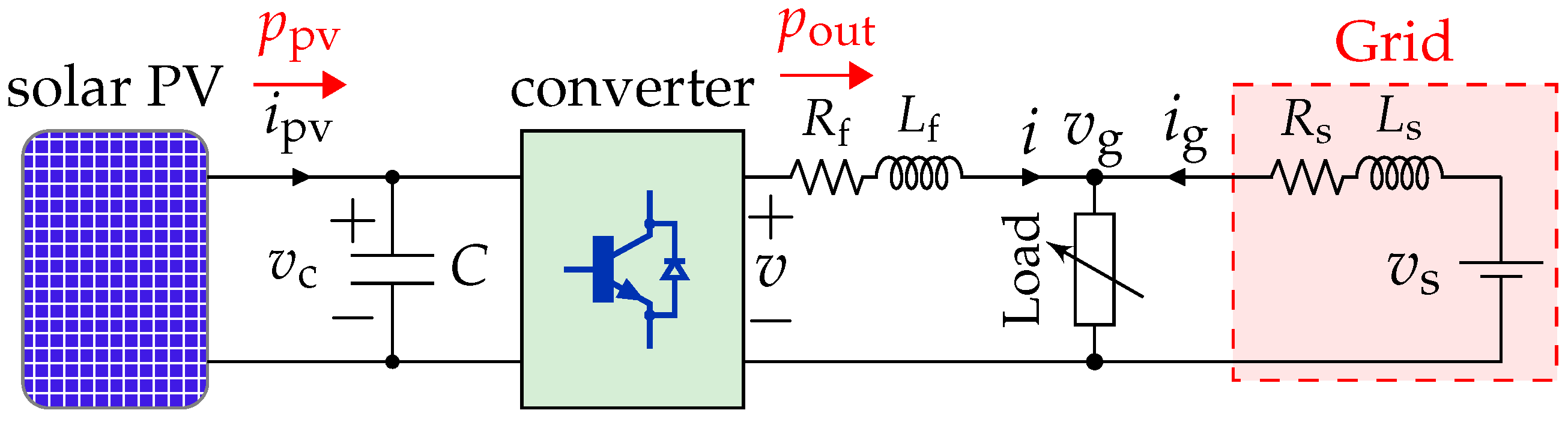
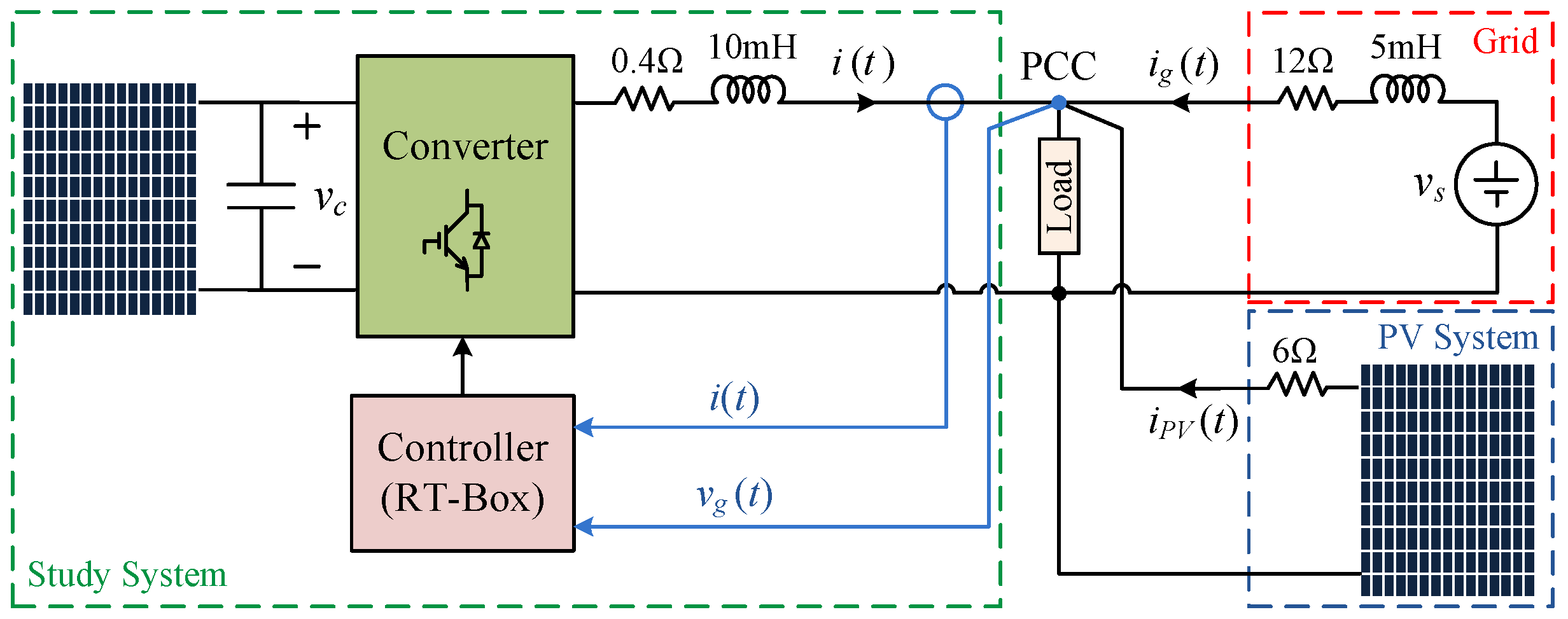
2. Study System and Problem Statement
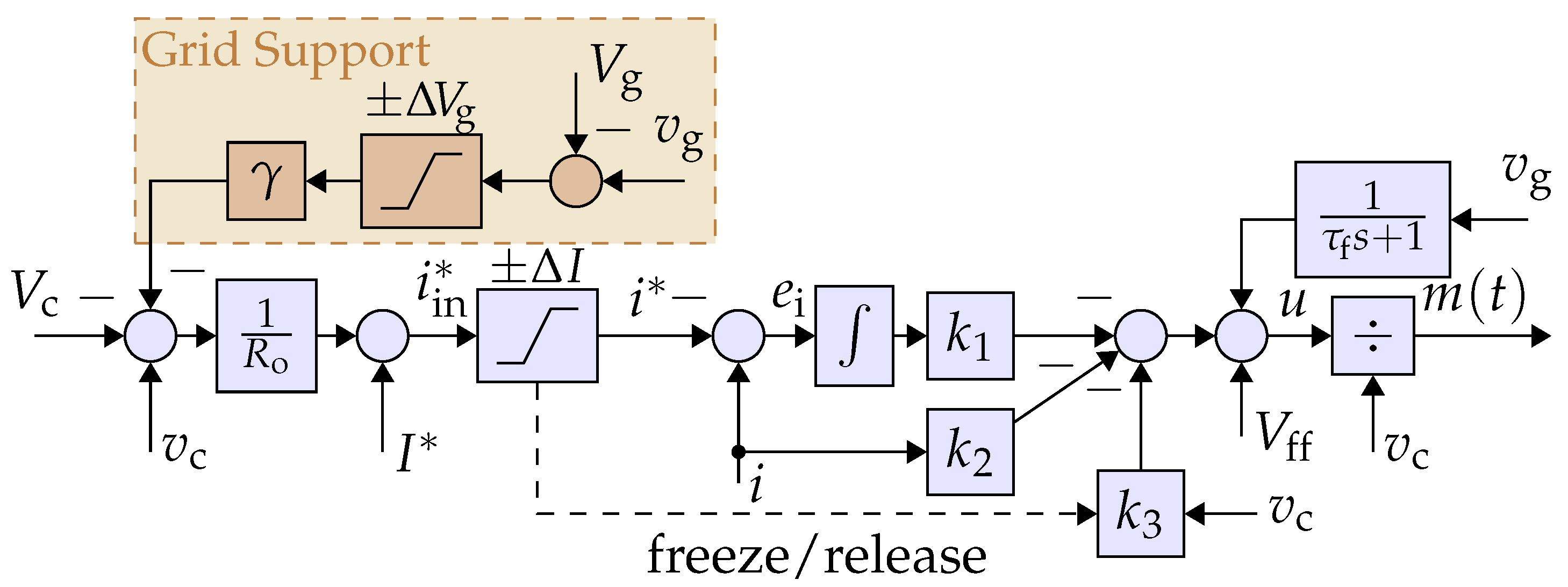
3. Proposed Controller: Structure and Design
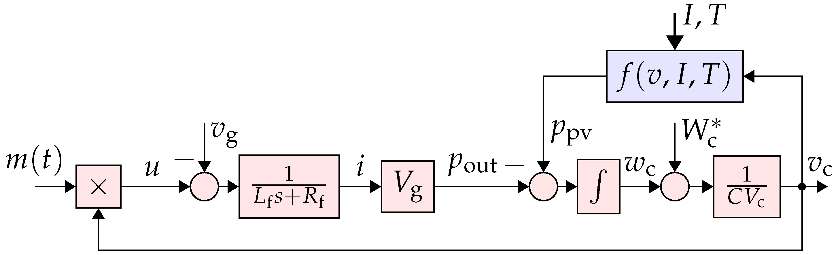
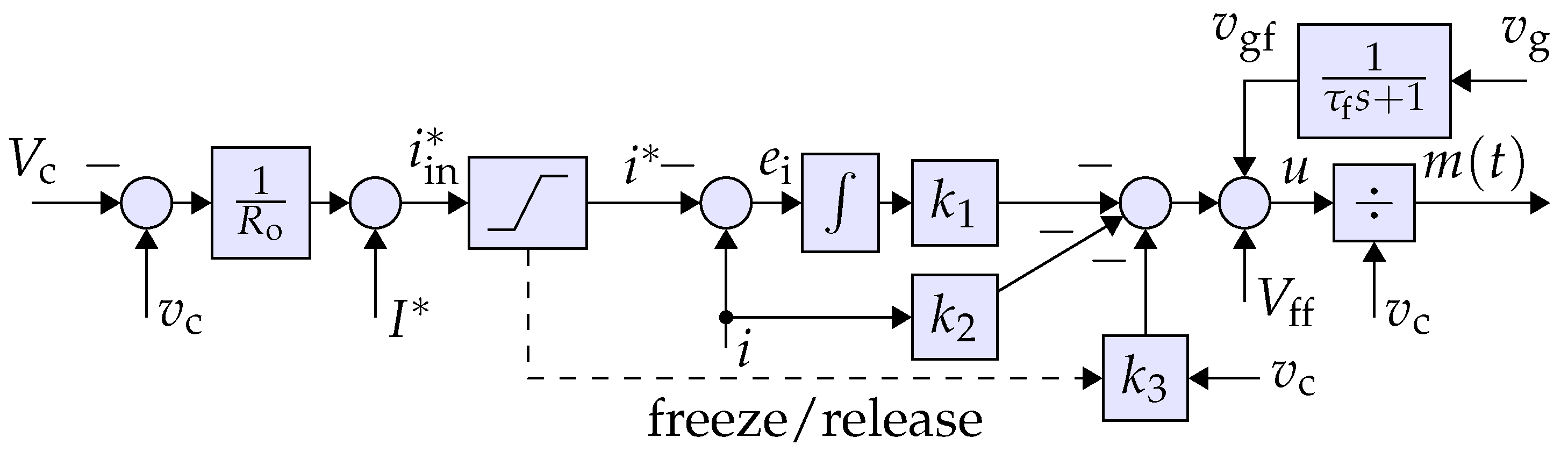
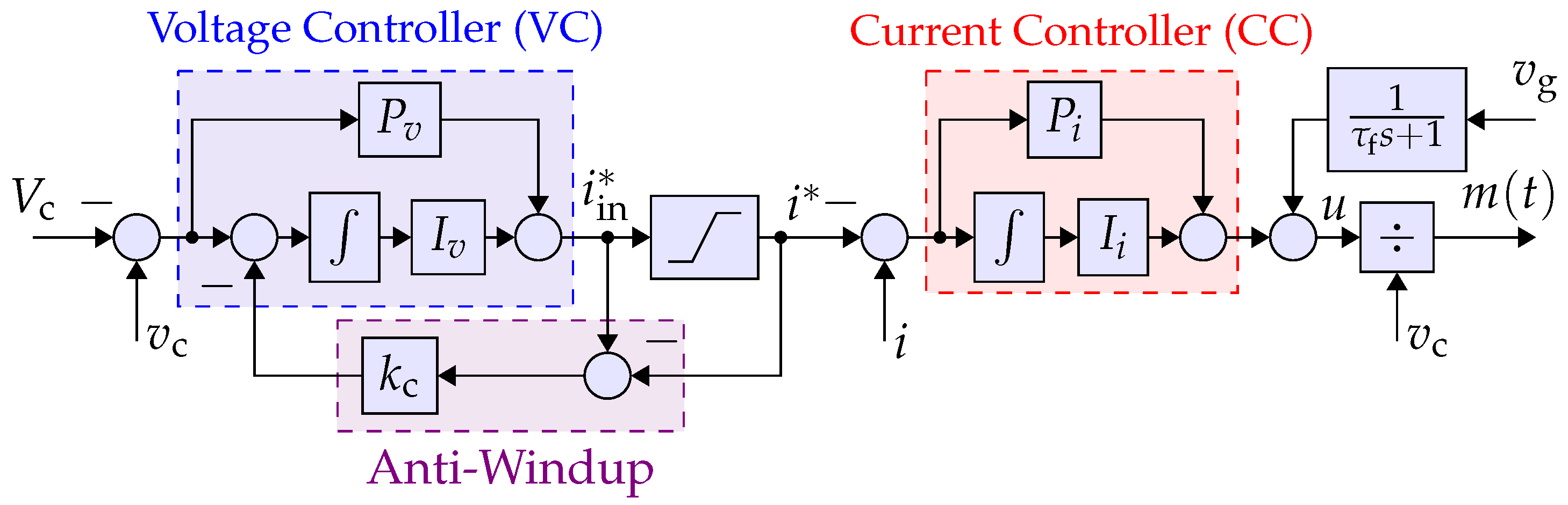
3.1. Structure
3.2. Grid Voltage Support Property
3.3. Capacitor Design
3.4. Design of VC Loop
3.5. Design of CC Loop
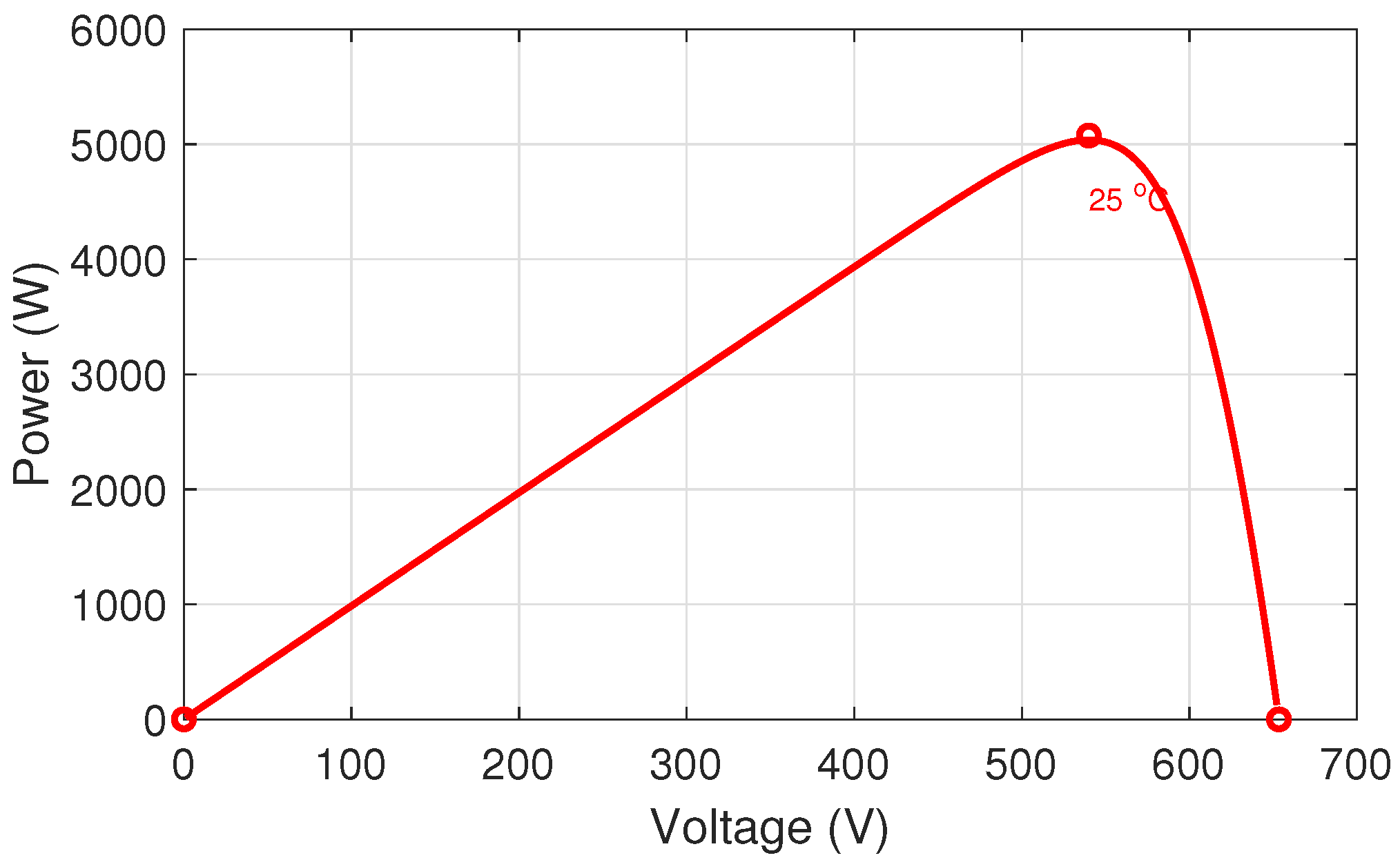
4. Design Rationale: Controlled Voltage Offset vs. MPPT
5. Simulation Results
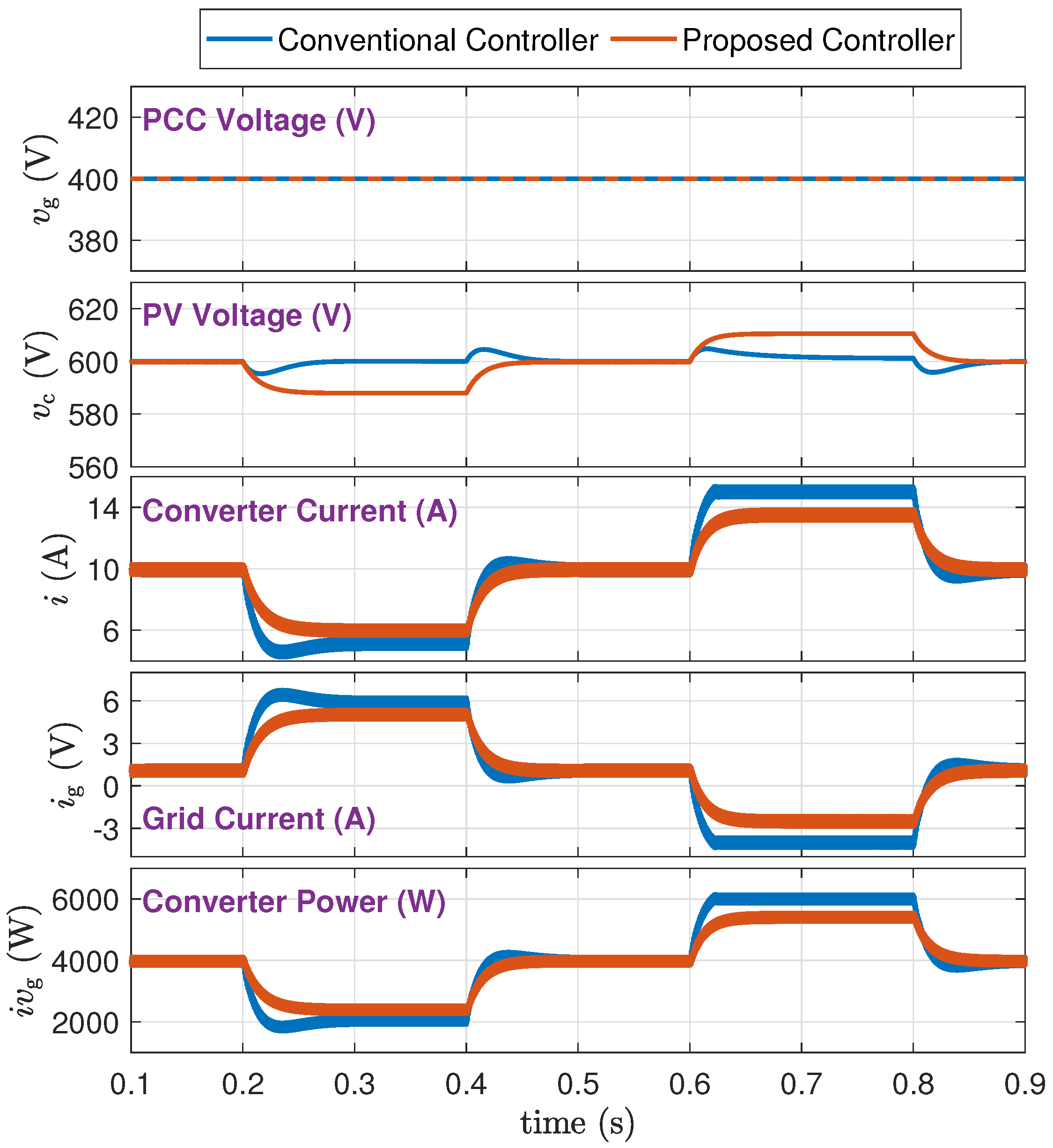
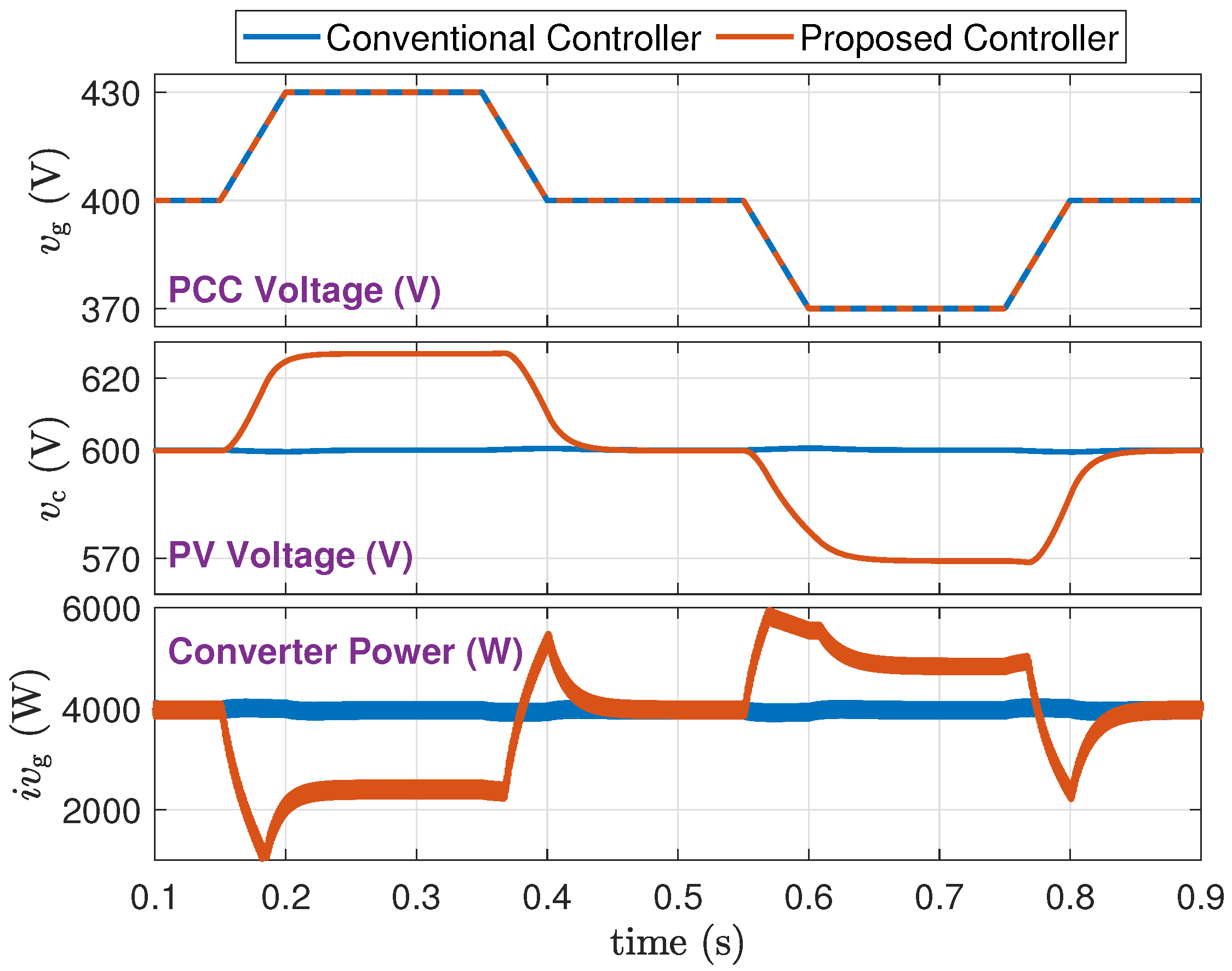
5.1. PV Power Disturbances (Scenario A)
- 1.
- From a trace of : the proposed method adaptively adjusts the PV voltage and power.
- 2.
- From a trace of : the proposed method reduces stress on both the converter and the grid. Specifically, lower fluctuations and steady values of indicate reduced power loss in the grid network.
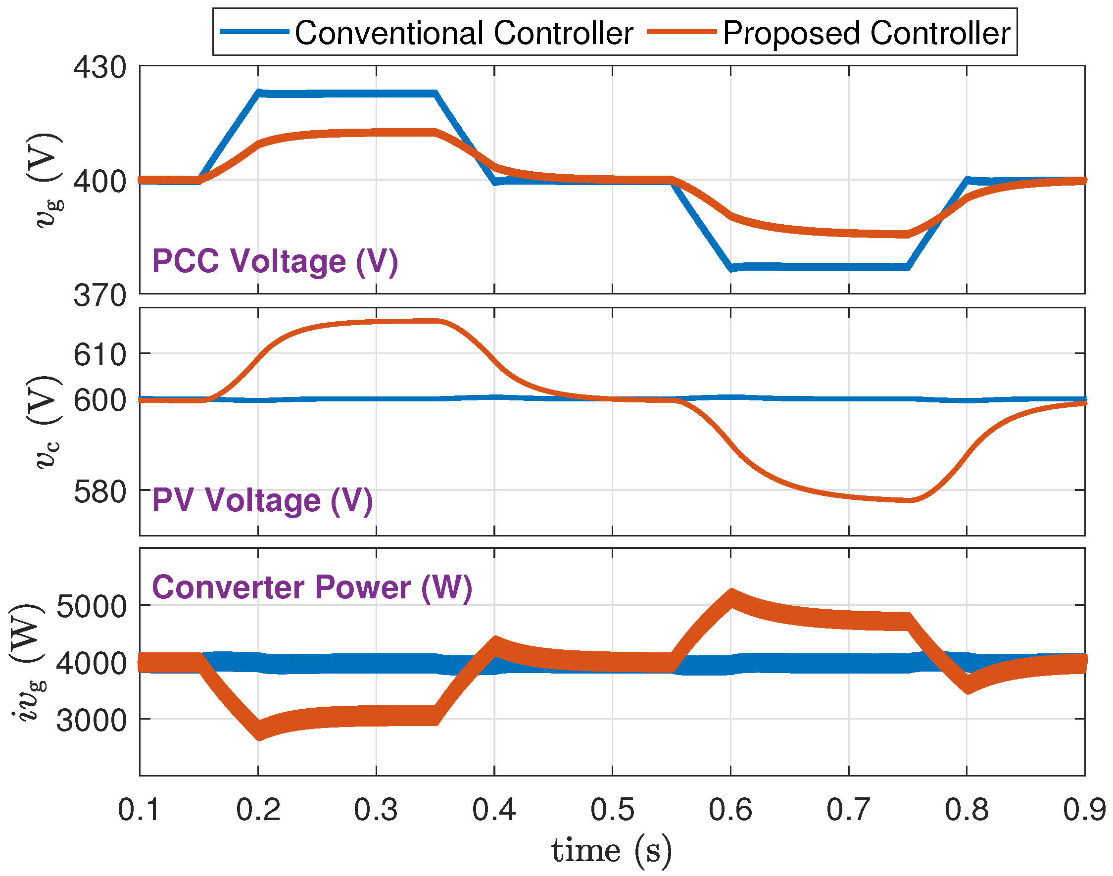
- 1.
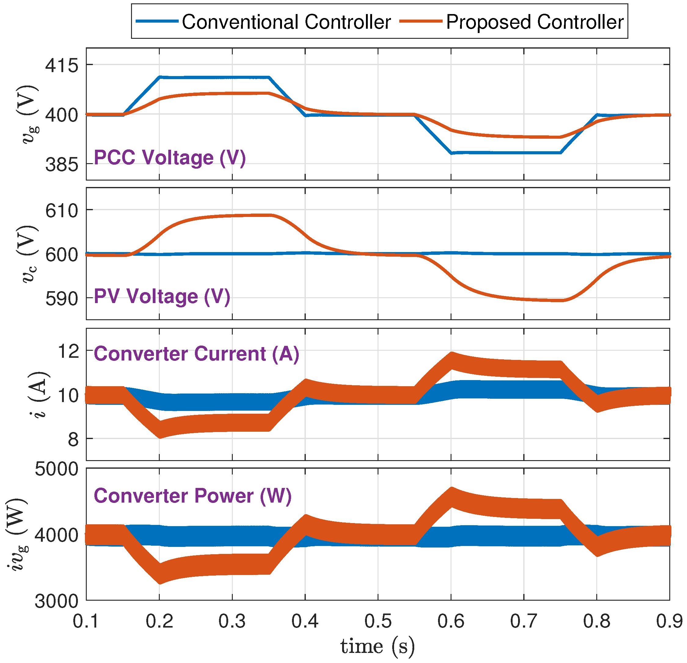
- From a trace of : The proposed method supports the grid voltage and maintains it within tighter limits. Specifically, when the PV power drops during 0.2 s to 0.4 s, the grid voltage drop is reduced from about 22 V to about 12 V. When the PV power increases from 0.6 s to 0.8 s, the grid voltage rise is reduced from about 22 V to about 7 V.
- 2.
- From a trace of : The proposed method adaptively adjusts the PV voltage and power.
- 3.
- From a trace of : The proposed method alleviates stress on both the converter and the grid. Specifically, lower fluctuations and steady values of indicate a reduction in power loss within the grid network.
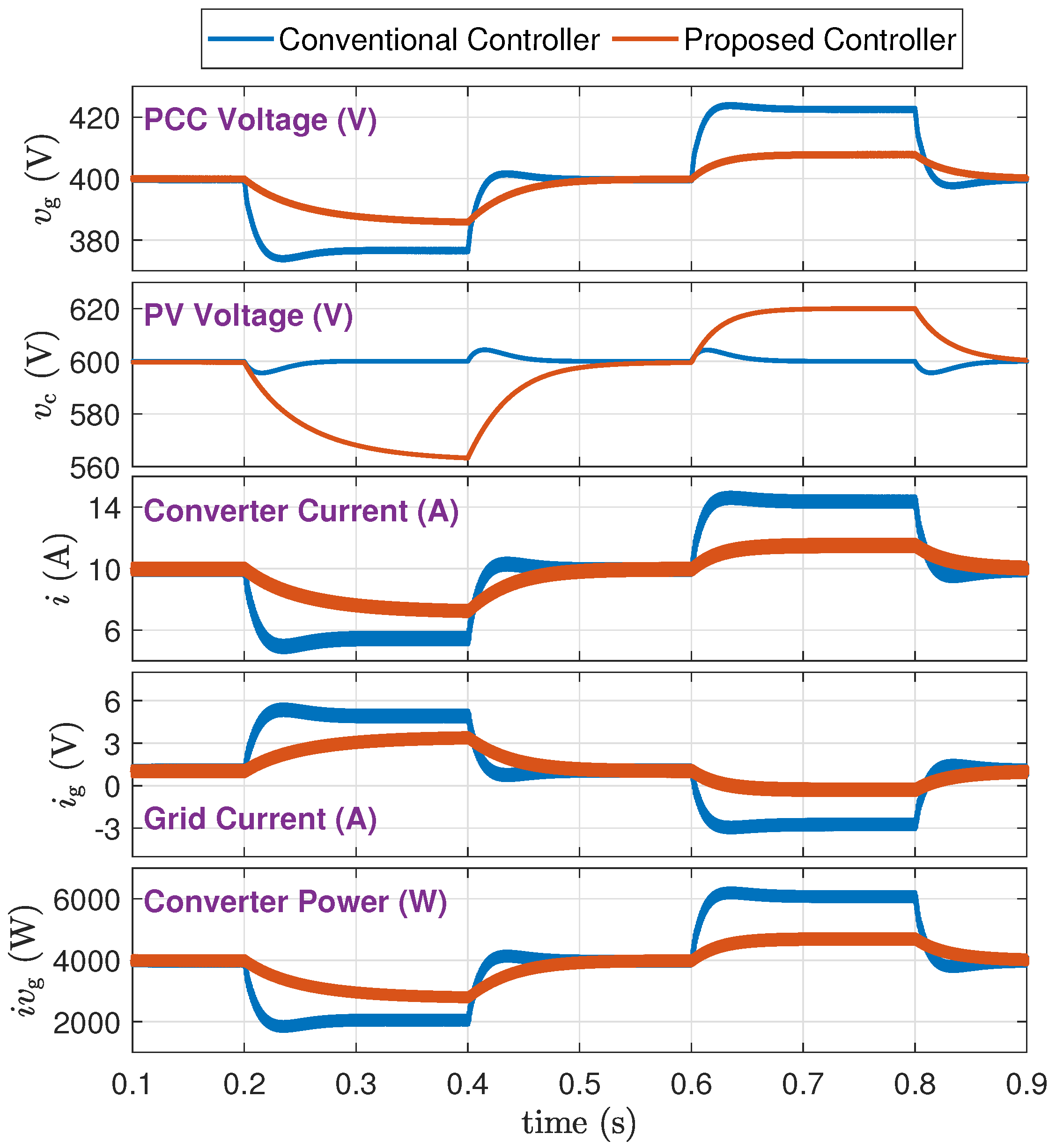
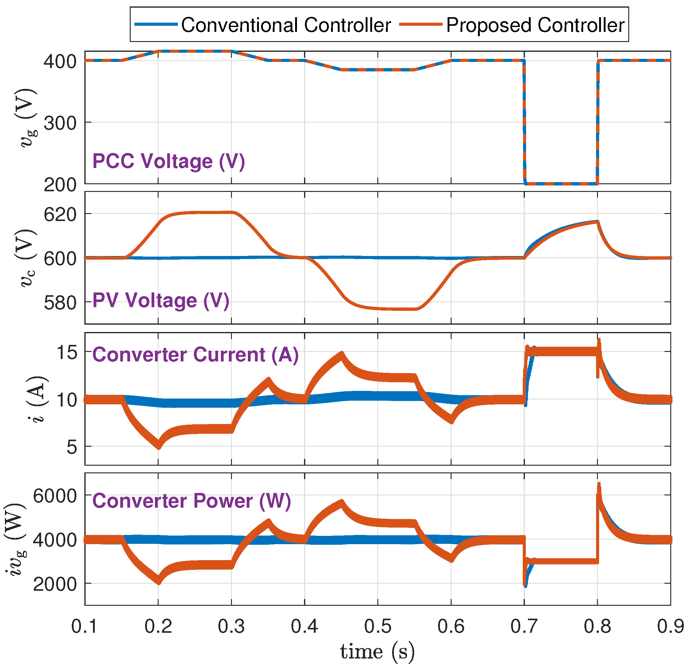
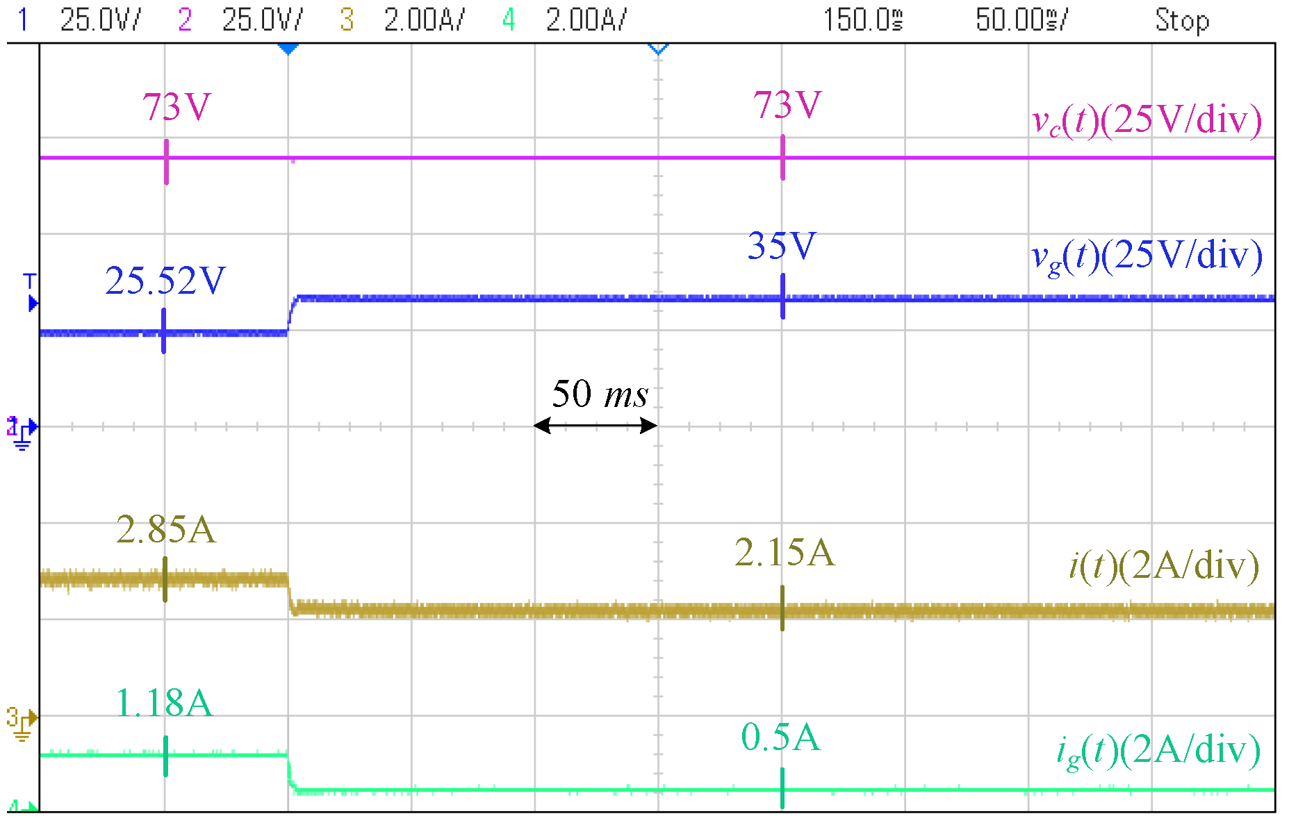
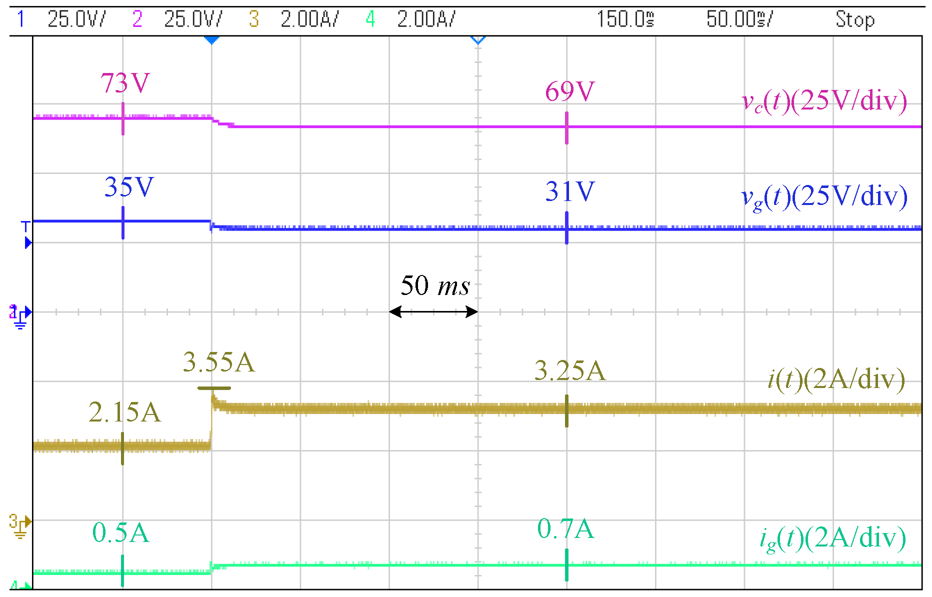
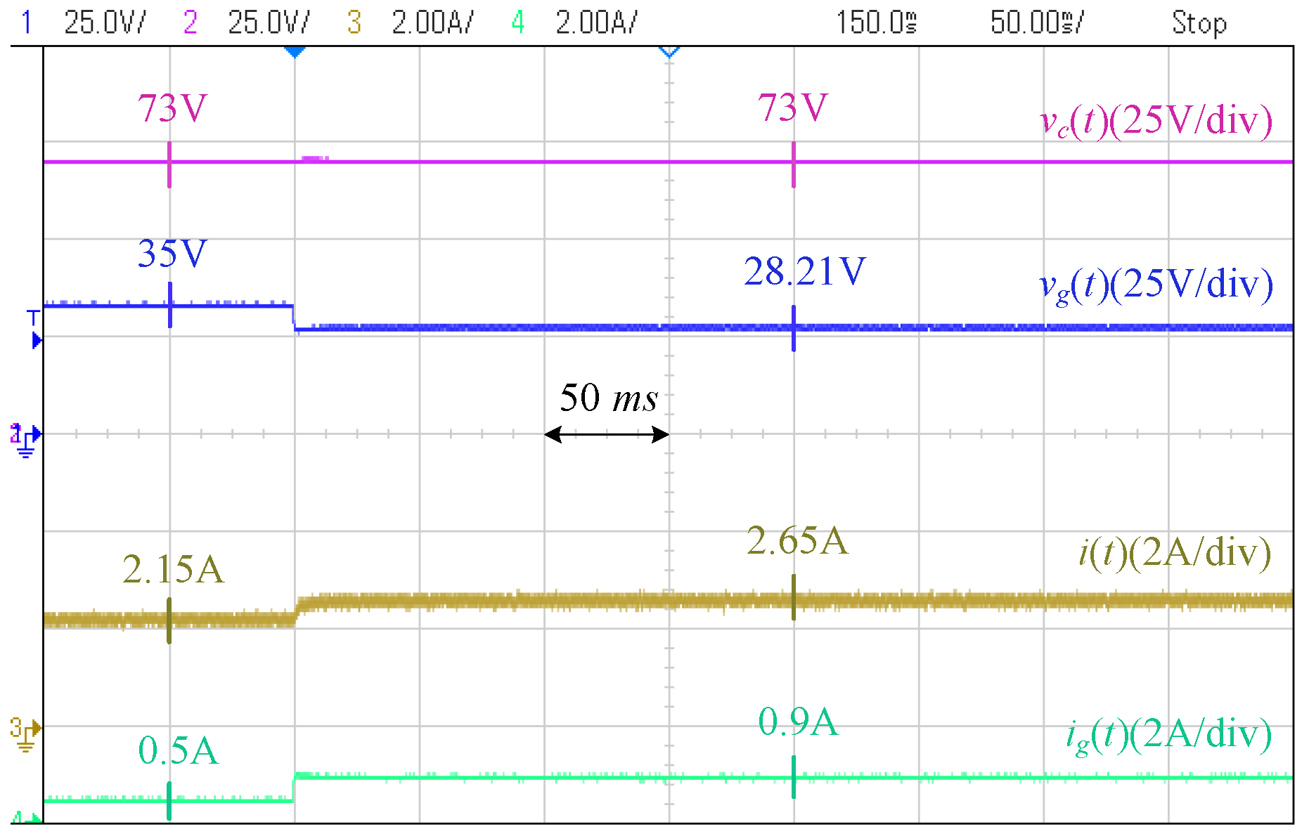
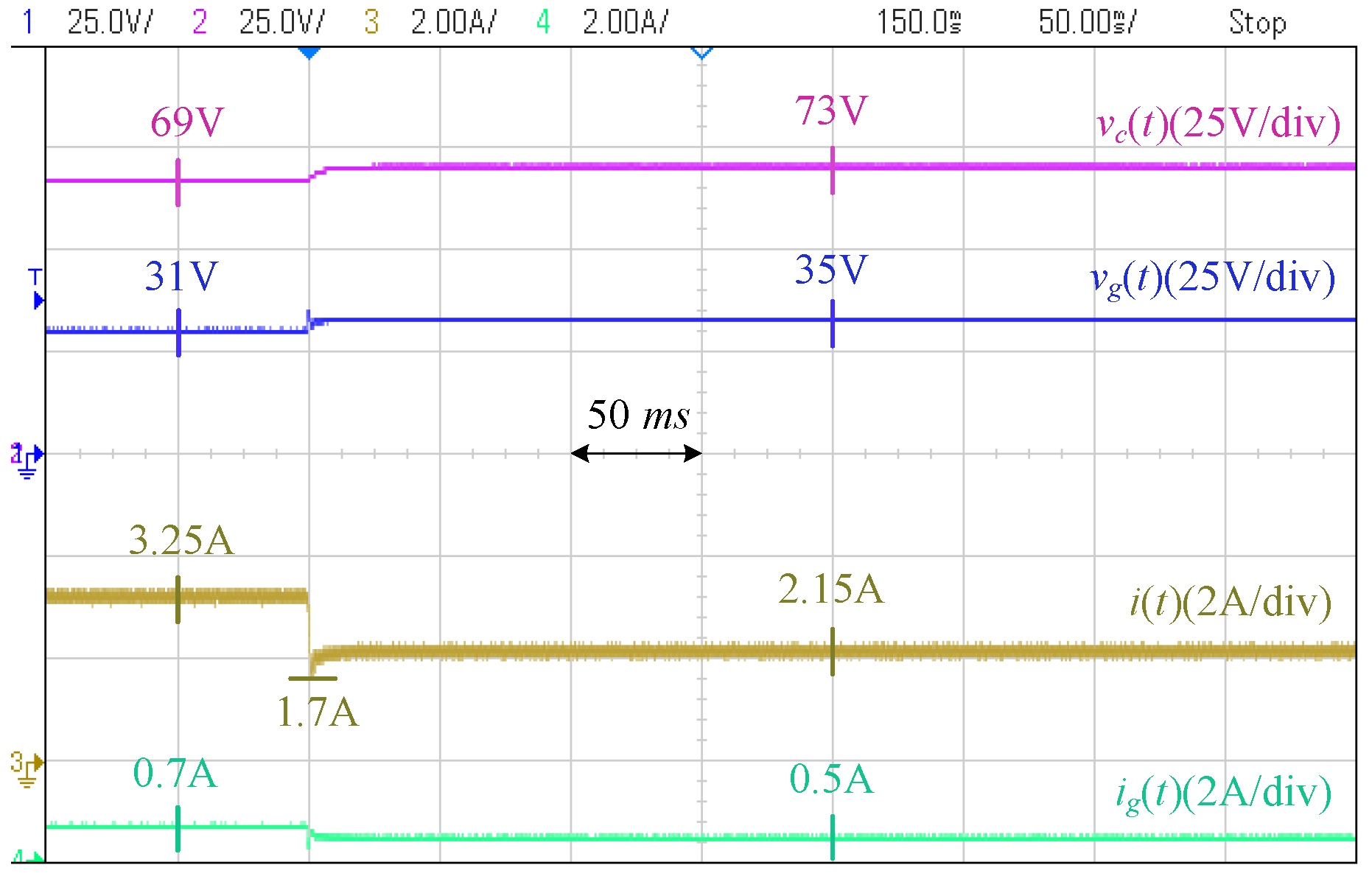
5.2. Grid Voltage Disturbances (Scenario B)
- 1.
- From a trace of : The proposed method adaptively adjusts the PV voltage and power.
- 2.
- From a trace of : The proposed method adaptively adjusts the power to support the grid.
- 3.
- Right before s, the converter current-limiting limits the converter current at 15 A.
- 1.
- From a trace of : The proposed method supports the grid voltage and maintains it within tighter limits. Specifically, the grid voltage fluctuations have been reduced by almost 50%.
- 2.
- From a trace of : The proposed method adaptively adjusts the PV voltage and power.
- 3.
- From a trace of : The proposed method adaptively adjusts the power to support the grid.
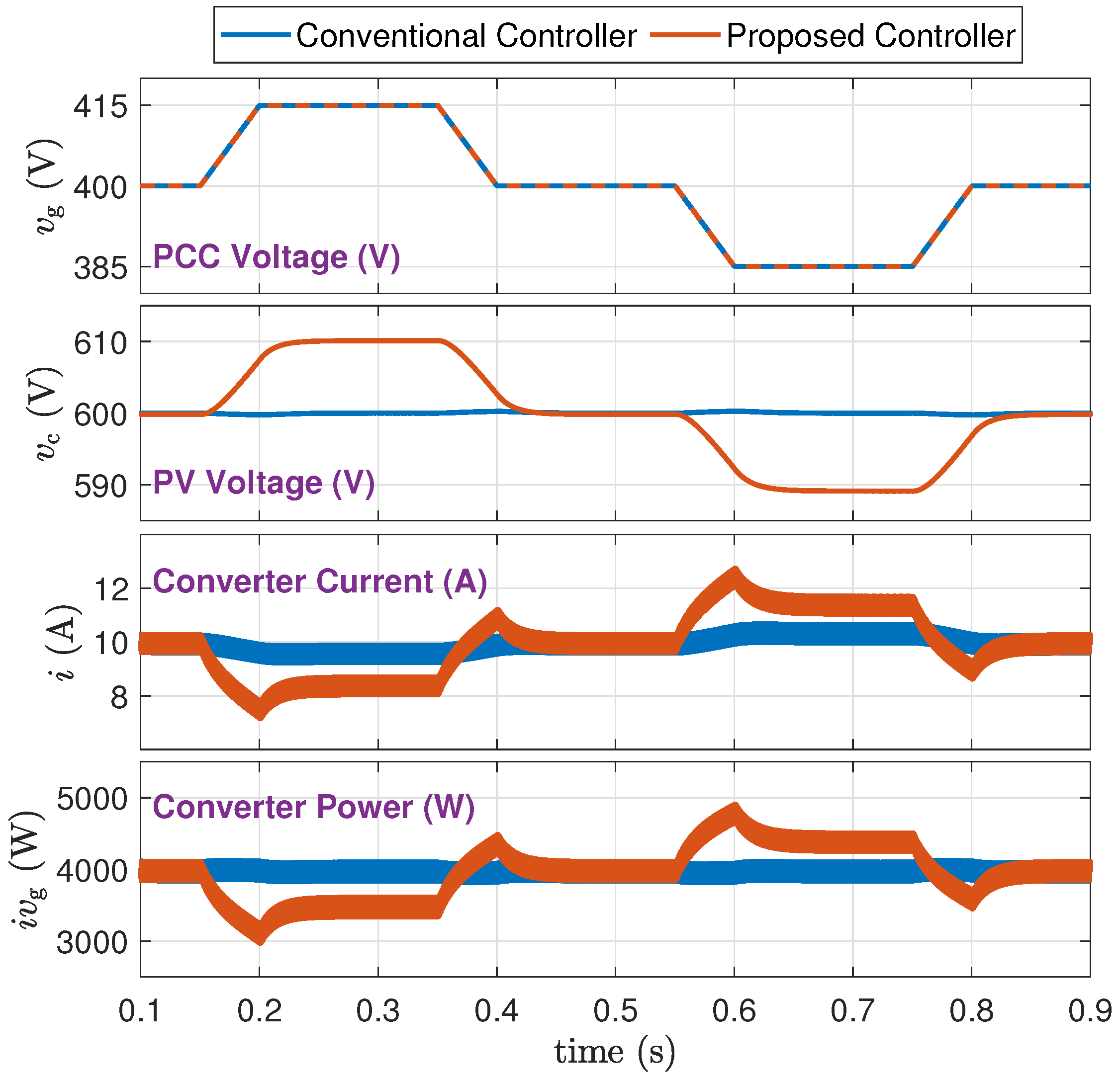
5.3. Impact of (Scenario C)
- 1.
- From a trace of : increasing proportionally increases the level of static and dynamic support that is provided by the proposed controller.
- 2.
- From a trace of : increasing widens the range of PV voltage to allow a higher level of grid support.
- 3.
- From a trace of : The converter current is successfully limited at 15 A whenever needed.
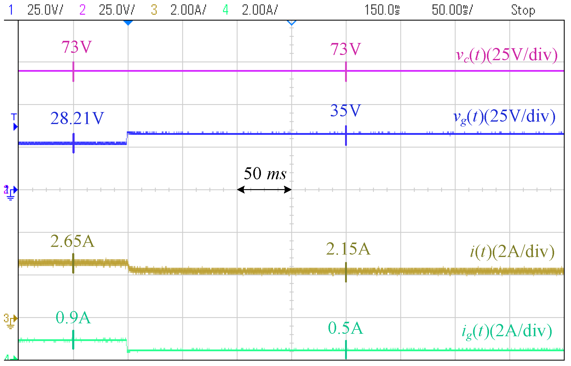
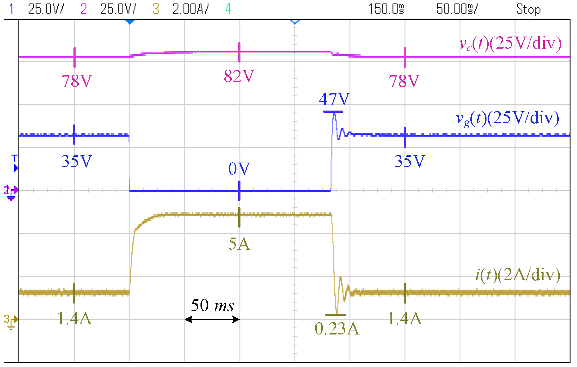
6. Experimental Results
6.1. Experimental Setup
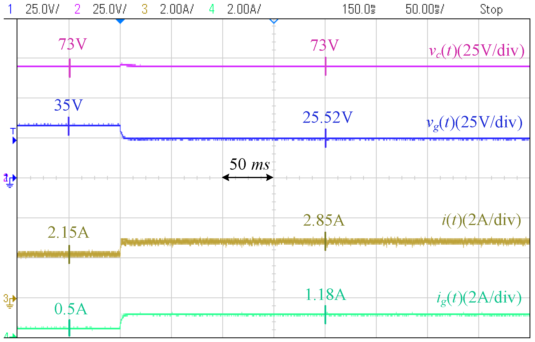
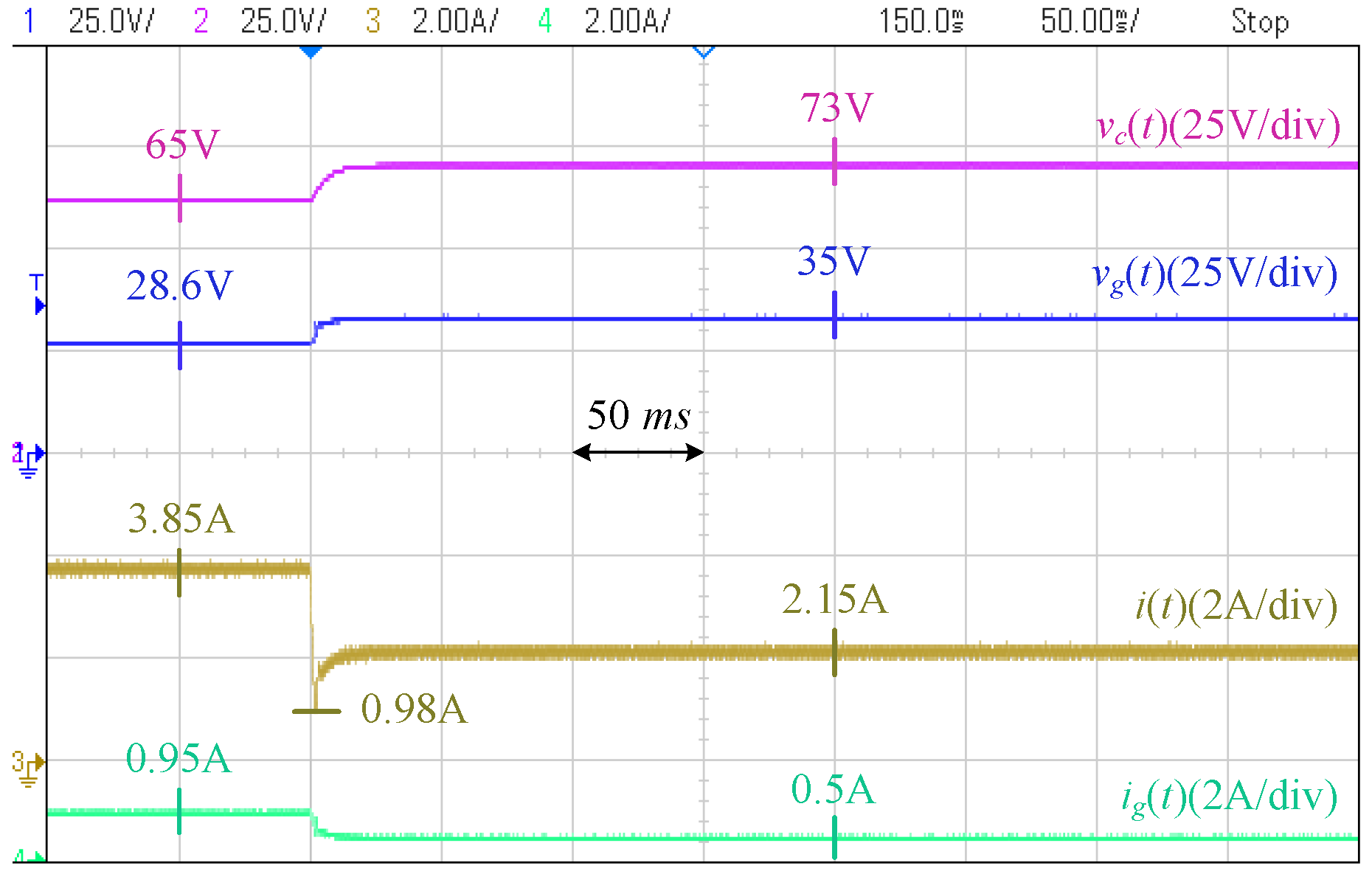
6.2. Experimental Results
7. Conclusions
Author Contributions
Funding
Data Availability Statement
Conflicts of Interest
References
- Yousefizadeh, S.; Bendtsen, J.D.; Khooban, M.H.; Blaabjerg, F.; Dragičević, T. Tracking Control for a DC Microgrid Feeding Uncertain Loads in More Electric Aircraft: Adaptive Backstepping Approach. IEEE Trans. Ind. Electron. 2019, 66, 5644–5652. [Google Scholar] [CrossRef]
- Dragicevic, T.; Vasquez, J.C.; Guerrero, J.M.; Skrlec, D. Advanced LVDC Electrical Power Architectures and Microgrids: A step toward a new generation of power distribution networks. IEEE Electrif. Mag. 2014, 2, 54–65. [Google Scholar] [CrossRef]
- Planas, E.; Andreu, J.; Gárate, J.I.; Martínez de Alegría, I.; Ibarra, E. AC and DC technology in microgrids: A review. Renew. Sustain. Energy Rev. 2015, 43, 726–749. [Google Scholar] [CrossRef]
- Wu, T.-F.; Chang, C.-H.; Lin, L.-C.; Yu, G.-R.; Chang, Y.-R. DC-Bus Voltage Control with a Three-Phase Bidirectional Inverter for DC Distribution Systems. IEEE Trans. Power Electron. 2013, 28, 1890–1899. [Google Scholar] [CrossRef]
- Ganesan, S.I.; Pattabiraman, D.; Govindarajan, R.K.; Rajan, M.; Nagamani, C. Control Scheme for a Bidirectional Converter in a Self-Sustaining Low-Voltage DC Nanogrid. IEEE Trans. Ind. Electron. 2015, 62, 6317–6326. [Google Scholar] [CrossRef]
- Alipoor, J.; Miura, Y.; Ise, T. Power System Stabilization Using Virtual Synchronous Generator with Alternating Moment of Inertia. IEEE J. Emerg. Sel. Top. Power Electron. 2015, 3, 451–458. [Google Scholar] [CrossRef]
- Beck, H.-P.; Hesse, R. Virtual synchronous machine. In Proceedings of the 9th International Conference on Electrical Power Quality and Utilisation, Barcelona, Spain, 9–11 October 2007; pp. 1–6. [Google Scholar]
- Zhong, Q.-C.; Weiss, G. Synchronverters: Inverters That Mimic Synchronous Generators. IEEE Trans. Ind. Electron. 2011, 58, 1–6. [Google Scholar] [CrossRef]
- Fang, J.; Lin, P.; Li, H.; Yang, Y.; Tang, Y. An Improved Virtual Inertia Control for Three-Phase Voltage Source Converters Connected to a Weak Grid. IEEE Trans. Power Electron. 2019, 34, 8660–8670. [Google Scholar] [CrossRef]
- Shucheng, T.; Ge, D.; Hui, Z.; Na, Z.; Xi, X. Virtual DC machine control strategy of energy storage converter in DC microgrid. In Proceedings of the IEEE Electrical Power and Energy Conference (EPEC), Ottawa, ON, Canada, 12–14 October 2016; pp. 1–5. [Google Scholar]
- Unamuno, E.; Paniagua, J.; Barrena, J.A. Unified Virtual Inertia for ac and dc Microgrids: And the Role of Interlinking Converters. IEEE Electrif. Mag. 2019, 7, 56–68. [Google Scholar] [CrossRef]
- Zhi, N.; Ding, K.; Du, L.; Zhang, H. An SOC-Based Virtual DC Machine Control for Distributed Storage Systems in DC Microgrids. IEEE Trans. Energy Convers. 2020, 35, 1411–1420. [Google Scholar] [CrossRef]
- Unamuno, E.; Barrena, J.A. Design and small-signal stability analysis of a virtual-capacitor control for DC microgrids. In Proceedings of the 19th European Conference on Power Electronics and Applications (EPE ECCE Europe), Warsaw, Poland, 11–14 September 2017; pp. 1–10. [Google Scholar]
- Zhu, X.; Meng, F.; Xie, Z.; Yue, Y. An Inertia and Damping Control Method of DC–DC Converter in DC Microgrids. IEEE Trans. Energy Convers. 2020, 35, 799–807. [Google Scholar] [CrossRef]
- Yang, Y.; Li, C.; Xu, J.; Blaabjerg, F.; Dragičević, T. Virtual Inertia Control Strategy for Improving Damping Performance of DC Microgrid with Negative Feedback Effect. IEEE J. Emerg. Sel. Top. Power Electron. 2021, 9, 1241–1257. [Google Scholar]
- Jami, M.; Shafiee, Q.; Bevrani, H. Dynamic Improvement of DC Microgrids Using a Dual Approach Based on Virtual Inertia. J. Mod. Power Syst. Clean Energy 2022, 10, 667–677. [Google Scholar]
- Zakerian, A.; Sharma, R.; Karimi-Ghartemani, M.; Karimi, H. Improving Stability and Power Sharing of Bidirectional Power Converters by Relaxing DC Capacitor Voltage. IEEE J. Emerg. Sel. Top. Power Electron. 2022, 10, 6973–6984. [Google Scholar] [CrossRef]
- Sharma, R.; Zakerian, A.; Karimi-Ghartemani, M. Local Controller for an Autonomous Grid-Supportive Battery Energy Storage System. IEEE Trans. Power Electron. 2022, 37, 2191–2202. [Google Scholar] [CrossRef]
- Swaminathan, G.V.; Periasamy, S.; Lu, D.D.-C. Capacitor Current Control Based Virtual Inertia Control of Autonomous DC Microgrid. IEEE Trans. Ind. Electron. 2023, 70, 6908–6918. [Google Scholar]
- Zhu, X.; Xie, Z.; Jing, S.; Ren, H. Distributed virtual inertia control and stability analysis of dc microgrid. IET Gener. Transm. Distrib. 2018, 12, 3477–3486. [Google Scholar] [CrossRef]
- Wang, Y.; Wang, C.; Xu, L.; Meng, J.; Hei, Y. Adjustable Inertial Response from the Converter with Adaptive Droop Control in DC Grids. IEEE Trans. Smart Grid 2019, 10, 3198–3209. [Google Scholar]
- Hosseinipour, A.; Hojabri, H. Virtual inertia control of PV systems for dynamic performance and damping enhancement of DC microgrids with constant power loads. IET Renew. Power Gener. 2018, 12, 430–438. [Google Scholar]
- Khajehoddin, S.A.; Karimi-Ghartemani, M.; Ebrahimi, M. Grid-supporting inverters with improved dynamics. IEEE Trans. Ind. Electron. 2018, 66, 3655–3667. [Google Scholar]
- Ebrahimi, M.; Khajehoddin, S.A.; Karimi-Ghartemani, M. A Single Stage Virtual Synchronous Machine. IEEE Int. Conf. Ind. Technol. (ICIT) 2019, 1643–1648. [Google Scholar]
- Karimi-Ghartemani, M.; Khajehoddin, S.A.; Jain, P.; Bakhshai, A. Linear quadratic output tracking and disturbance rejection. Int. J. Control. 2011, 84, 1442–1449. [Google Scholar]
- MATLAB. Available online: https://www.mathworks.com (accessed on 11 December 2023).
- Yazdani, A.; Iravani, R. Voltage-Sourced Converters in Power Systems: Modeling, Control, and Applications; John Wiley & Sons: Hoboken, NJ, USA, 2010. [Google Scholar]
- RT BOX. Available online: https://www.plexim.com/products/rt_box (accessed on 20 January 2021).


| Parameter | Symbol | Value | Unit |
|---|---|---|---|
| PV-side Voltage | 600 | V | |
| PCC Voltage | 400 | V | |
| Grid Resistance (Weak Grid) | 6 | ||
| Grid Inductance (Weak Grid) | 5 | mH | |
| Grid Resistance (Strong Grid) | 0 | ||
| Grid Inductance (Strong Grid) | 0 | mH | |
| Filter Inductance | 5 | mH | |
| Parasitic Resistance | 50 | m | |
| Switching Frequency | 10 | kHz | |
| Power Rating | 4 | kW | |
| Current Limits | ±15 | A | |
| Local Load | 4.4 | kW | |
| PV-side Capacitor Size | C | 4.17 | mF |
| Parameter | Symbol | Value |
|---|---|---|
| Conventional Voltage Control P Gain | 0.62 | |
| Conventional Voltage Control I Gain | 27.5 | |
| Conventional Current Control P Gain | −13.9 | |
| Conventional Current Control I Gain | −15,753 | |
| Voltage Limits (in Grid Support Unit) | ||
| Converter Current Limits | ||
| Grid Support Gain | 2 | |
| Controller Gains | [28,184 | |
| Controller Gain | 3 |
Disclaimer/Publisher’s Note: The statements, opinions and data contained in all publications are solely those of the individual author(s) and contributor(s) and not of MDPI and/or the editor(s). MDPI and/or the editor(s) disclaim responsibility for any injury to people or property resulting from any ideas, methods, instructions or products referred to in the content. |
© 2025 by the authors. Licensee MDPI, Basel, Switzerland. This article is an open access article distributed under the terms and conditions of the Creative Commons Attribution (CC BY) license (https://creativecommons.org/licenses/by/4.0/).
Share and Cite
Zakerian, A.; Karimi-Ghartemani, M. Robust DC Grid Voltage Support in a Single-Stage PV Converter. Electronics 2025, 14, 1396. https://doi.org/10.3390/electronics14071396
Zakerian A, Karimi-Ghartemani M. Robust DC Grid Voltage Support in a Single-Stage PV Converter. Electronics. 2025; 14(7):1396. https://doi.org/10.3390/electronics14071396
Chicago/Turabian StyleZakerian, Ali, and Masoud Karimi-Ghartemani. 2025. "Robust DC Grid Voltage Support in a Single-Stage PV Converter" Electronics 14, no. 7: 1396. https://doi.org/10.3390/electronics14071396
APA StyleZakerian, A., & Karimi-Ghartemani, M. (2025). Robust DC Grid Voltage Support in a Single-Stage PV Converter. Electronics, 14(7), 1396. https://doi.org/10.3390/electronics14071396