Abstract
Recent years have seen increasing attention paid to autonomous decentralized microgrids that are disaster-resistant and suitable for local consumption of locally generated renewable energy power. Although various methods have been discussed for achieving microgrids through autonomous decentralized cooperative control, there are few reports that have reached the stage of field testing. In this study, I propose a novel method for configuring the baseline of DC microgrids, where storage batteries are distributed and directly connected to the DC bus. I have built a testbed to demonstrate the operation of the DC microgrid through autonomous decentralized cooperative control. My method simply employs the droop characteristics inherent in batteries, and I introduce the new concept of a ‘weakly coupled grid’. This approach allows the realization of microgrids with autonomous decentralized cooperative control without the need for advanced and complex grid control technologies using DC/DC converters, and with a simple configuration. Additionally, by directly connecting batteries to the baseline, I introduce a grid stabilization method achieved by imparting electrical inertia to the baseline. This paper describes the construction method, the operation principle, and safe and stable operational methods for autonomous decentralized microgrids using this approach, aiming to serve as a guide for those who wish to build autonomous decentralized controlled microgrids in practice.
1. Introduction
In recent years, large-scale and catastrophic natural disasters have become increasingly frequent in many countries around the world. The primary cause of these disasters is believed to be global warming, and the reduction in greenhouse gas emissions, such as CO2, has become an urgent issue. Therefore, efforts are being made to shift from fossil fuels to renewable energy sources in power generation. However, there are several challenges to overcome. Power generation by renewable energy, such as solar or wind power, is intermittent and unstable, and as the ratio of power generated by renewable energy increases, it can destabilize power grid systems. Furthermore, there is insufficient capacity in the existing power grids to accommodate additional renewable energy power generation. Additionally, the existing power grids, which are based on large-scale centralized power generation and long-distance transmission, are vulnerable to major disasters and can also be targets of terrorist attacks.
Against this backdrop, regional microgrids based on the principle of local production and consumption of electricity are gaining attention [1,2,3,4,5]. Particularly in residential areas, direct current (DC) microgrids that connect small power generators using renewable energies, such as solar panels and wind turbines, and storage batteries through DC buses are drawing keen interest [6,7,8,9,10,11]. Although DC microgrids require the installation of dedicated power lines, they are simpler to control and offer greater flexibility in grid configuration compared to alternating current (AC) grids. Field testing and social implementations have already been conducted in various parts of the world, although control methods and baseline voltages vary [12,13,14]. However, even if a microgrid is constructed, maintaining and operating it over the long term is not easy.
Microgrid control methods include centralized control, decentralized control, hierarchical control, and various other approaches [15,16,17,18,19,20,21]. The centralized control method, illustrated in Figure 1a, is employed in existing power grids. This approach relies on centralized controllers situated in the central control rooms of power companies, which monitor and manage the entire grid. Several devices within the grid are connected to the centralized controller via communication lines, allowing for unified management of the grid. This method enables optimization across the entire grid. However, if the centralized controller fails or the communication lines are disrupted, the entire grid becomes uncontrollable, making it vulnerable to large-scale disasters [22,23,24,25].
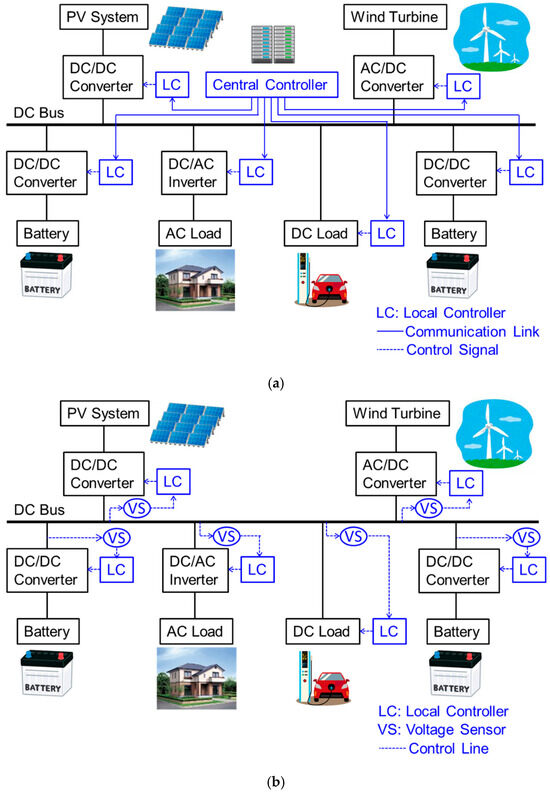
Figure 1.
Control methods of power grids: (a) centralized control method; (b) autonomous decentralized cooperative control (ADCC) method.
In contrast, the autonomous decentralized cooperative control (ADCC) method, as depicted in Figure 1b, is a unique control method that does not involve a centralized controller and communication lines that connect devices. Each device connected to the grid independently makes decisions and controls itself [26,27,28,29,30,31,32]. This method lacks the framework to monitor the entire grid, making overall grid optimization challenging and limiting it to local or partial optimization of grids. Nevertheless, even if part of the grid is damaged, the remaining parts can still function to some extent, making this method effective during disasters. Additionally, this approach allows for relatively easy modifications and expansions of the grid, enabling the creation of a flexible and scalable grid. However, since the ADCC does not have a mechanism for monitoring the entire grid, each device does not know the status of the entire grid. Under such circumstances, the issue is how each device can autonomously control itself.
The key is for each device to understand the situation around it as accurately as possible. Although ADCC does not know the situation of the entire grid, it is possible for each device to understand the situation of the grid around it to a certain extent. (That is the subject of this paper, which I will explain in detail later.) On that basis, some rules regarding grid use are established so as not to have a negative impact on the grid, and the system is such that all devices follow those rules and achieve their own purpose. For example, the purpose of each device is to feed renewable-energy-generated electricity into the grid in the case of a renewable energy generator such as PV or wind power. Also, in the case of a power load, it is to obtain power from the grid and start up when it is needed. However, in that case, it is necessary to avoid having a negative impact on the grid, so some kind of rule (Grid Code) regarding grid use is necessary. (That is also the subject of this paper, as I will explain in detail later.)
By introducing such a system, it is possible to maintain and operate the grid without centralized controllers and communication lines. In essence, this system establishes rules for proper grid utilization, with each device adhering to those rules while exercising self-restraint. This approach creates a democratic grid that can be effectively maintained and managed.
This paper focuses on the operating principles, construction methods, control methods, and safety measures of DC microgrids with ADCC, which enable practical use. Specifically, I propose an ADCC DC microgrid created by directly connecting distributed small batteries to the baseline. I built an experimental testbed for this type of DC microgrid to verify the feasibility of the method and have successfully operated it stably for over three years. Herein, I share the knowledge and challenges gained from this experience, hoping to provide useful insights for those planning to construct microgrids in the future.
2. Key Elements in Grid Control
Regardless of ADCC, there are two important factors in grid control: (1) droop control, which allows the coordinated operation of multiple generators within the grid autonomously, and (2) electrical inertia, which is essential for stabilizing the grid. Droop control is used in existing power grid systems to enable multiple synchronous generators to cooperate while sharing the load and supplying power to the grid. Specifically, each synchronous generator has droop characteristics, as shown in Figure 2a, where the generator’s rotational speed decreases as the load rate increases, causing the output voltage or frequency to decrease. This helps counteract frequency changes in the system by increasing (decreasing) the load rate when the system frequency decreases (increases) due to some factor. Additionally, because each synchronous generator has this characteristic, neighboring synchronous generators can share the load and operate in coordination.
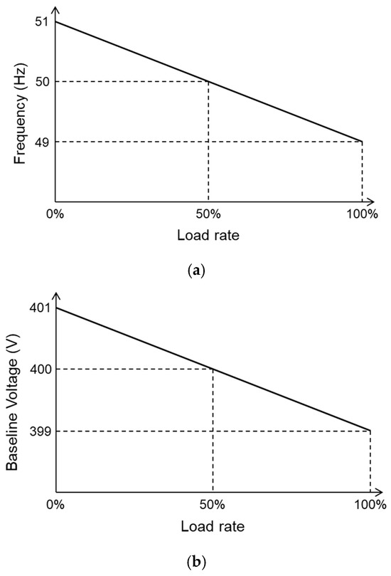
Figure 2.
Droop characteristics of (a) synchronous generators; (b) DC/DC converters.
On the other hand, electrical inertia is very important for stabilizing the grid. When using electrical appliances at home, some appliances require several times their rated power consumption for a very short time when the switch is turned on. This power consumed at the start of the appliance is called inrush power or starting power, and the reason why even large electrical appliances can start up normally is because of the significant electrical inertia delivered to the household power plug. In existing power systems, there is essentially no energy storage, so there is always a need to balance generation and consumption (the principle of simultaneous power supply and demand). Therefore, a mechanism to cope with instantaneous increases in power load is necessary, and in power systems, power plant generators handle this. In other words, the source of electrical inertia is the rotational kinetic energy stored in the heavy turbines of thermal and hydro powerplant generators. This energy is instantaneously (within a few microseconds) converted into electrical energy and released into the grid system in response to sudden increases in power consumption. Since wind turbines in wind power generation do not have heavy turbines or synchronization mechanisms to store kinetic energy, there is a concern that the introduction of wind power generation will reduce the electrical inertia of the existing power system.
The two factors mentioned above are also important in the case of DC grids, and these mechanisms must also be present in ADCC DC microgrids. In DC microgrids, distributed power sources such as generators and batteries are generally connected to the baseline via DC/DC converters. Therefore, the DC/DC converters have droop characteristics with respect to the baseline voltage, as shown in Figure 2b, to enable coordinated operation of the distributed power sources [33,34,35]. However, as the number of distributed power sources increases, the number of droop parameters to be handled also increases, making control more complex. Therefore, I devised a method to achieve coordinated operation by focusing on the droop characteristics inherent in the battery itself. This will be discussed in Section 4.
Electrical inertia in DC grids is also crucial for stabilizing the grid and coping with sudden changes in power load. For instance, when rapid charging of electric vehicles (EVs) begins, the baseline voltage drops due to a sudden increase in power load. If the baseline has significant electrical inertia, this voltage drop will be small; however, if the electrical inertia is low, a large voltage drop will occur. In general DC microgrids, DC/DC converters connected to distributed power sources handle this change [36,37]. When the baseline voltage starts to drop, control works to supply more power from distributed power sources such as generators or batteries to the baseline. This can handle some increases in power load, but if the power supplied exceeds the rated power of the DC/DC converters, protection circuits will activate and stop the output. Additionally, this control requires a few milliseconds, during which the power load may give up on starting, or in the worst-case scenario, the grid may go down.
From this perspective, electrical inertia in DC grids can be considered the ‘maximum power’ that can be instantaneously extracted from a certain point on the baseline or power line. Here, ‘instantaneous’ specifically refers to a period ranging from a few seconds to at most a few tens of seconds, differing from power supply sustainability over several hours and referring solely to instantaneous force. This is a very short time sufficient to start household appliances requiring high inrush power. The power sustainability for long-term operation of appliances is related to battery capacity and is distinct from electrical inertia.
3. DC Grid with Distributed Batteries Directly Connected to the Baseline
Based on that background, I propose a DC microgrid, as shown in Figure 3, where multiple small batteries are directly connected to the baseline. In a typical DC microgrid, distributed power sources such as batteries are connected to the baseline via DC/DC converters. This makes it possible to connect batteries with terminal voltages different from the baseline voltage, as DC/DC converters perform voltage conversion. Additionally, DC/DC converters allow free power transfer between the batteries and the baseline. However, when directly connecting batteries to the baseline, the terminal voltage of the batteries must match the baseline voltage. This can be achieved by connecting multiple battery cells in series to form the bulk battery, but some constraints may arise if different types of battery cells with varying cell voltages are mixed. Nonetheless, the following significant advantages outweigh these drawbacks:
- Utilizing the droop characteristics inherent in the batteries themselves for coordinated operation among distributed batteries.
- Directly delivering the large electrical inertia of the batteries to the baseline without passing through the DC/DC converters, resulting in substantial electrical inertia for the baseline.
- Since each distributed battery is directly connected to the baseline, the state of charge (SoC) of each battery spontaneously equalizes over time.
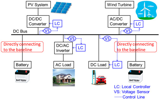
Figure 3.
My method of directly connecting distributed batteries to the baseline.
These aspects will be discussed in detail in the following sections.
4. Inherent Droop Characteristics of Batteries
The droop characteristics inherent to batteries can be formulated from the equivalent circuit of batteries. The basic equivalent circuit of a battery consists of an electromotive force E in series with an internal resistance ri, as shown in Figure 4a. If a load resistance is connected, and the value of the load resistance RL is equal to ri, the battery can deliver the maximum power, defining a load rate of 100%. When a load RL of any value is connected, the load rate α is given by
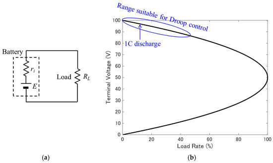
Figure 4.
Droop characteristics of a battery: (a) basic equivalent circuit of a battery; (b) relationship between the load rate α and the terminal voltage Vt.
Meanwhile, the terminal voltage Vt of the battery, given the electromotive force E, is
The relationship between the load rate α and the terminal voltage Vt is thus
This relationship is depicted in Figure 4b, representing the droop characteristics of inherent batteries. Generally, as the load rate increases (i.e., as the output current increases), the terminal voltage drops due to the voltage drop across the internal resistance. However, the droop coefficient changes its sign depending on whether the value of the load resistance is greater than or less than the internal resistance of the battery.
To achieve ADCC, it is necessary to use the region where the droop coefficient is negative, i.e., the upper half of the graph, when the load resistance is greater than the internal resistance of the battery. Moreover, where the load rate is 50% or less, a nearly linear relationship is observed between the load rate and the terminal voltage, enabling stable droop operation.
Equation (3) indicates that the droop characteristics of the battery do not depend on the value of internal resistance. Consequently, even if the battery deteriorates and its internal resistance increases, the load rate will be maintained at the same value as when it was new, as long as the value of the electromotive force (equal to the terminal voltage without loading), does not change. Furthermore, even with a mix of different types of batteries, if their electromotive force is uniform, the load rate can be equalized across the batteries. While the electromotive force of batteries naturally depends on the SoC, as will be explained in Section 9, the electromotive force of lithium-ion batteries can be regarded as nearly constant within a specific range of SoC values. Thus, by directly connecting batteries of the same type and equal terminal voltage to the baseline, the inherent droop characteristics of the batteries can be leveraged for cooperative operation.
Measurement of the internal resistance of a lithium iron phosphate (LiFePO4) battery rated at 51.2 V, 40 Ah showed that the internal resistance was approximately 75 mΩ, depending on the state of charge (SoC) and the magnitude of the discharge current. Therefore, the load rate for a 1C (40 A) discharge of this battery is approximately 12%, and under normal usage conditions, the load rate remains relatively low, which allows for effective droop control.
Thus, by directly connecting batteries with a matched terminal voltage to the baseline, ADCC can be achieved using the batteries’ inherent droop characteristics.
5. Electrical Inertia in DC Grids
In Section 2, I defined electrical inertia in DC grids as ‘the maximum power that can be instantaneously extracted from a point on the baseline or power line’. The term ‘instantaneous’ refers to the time it takes for typical power load equipment to complete the startup process and enter steady-state operation, specifically ranging from a few seconds to several tens of seconds. Electrical inertia in existing power systems also operates within this time frame. Therefore, the ability to supply power over several hours is different in both meaning and unit (J), as it is the electrical energy that can be supplied. Consequently, the unit for electrical inertia in DC grids should be watt (W).
If we consider the electrical equivalent circuit of a battery, as shown in Figure 4a, the maximum power Pmax that can be extracted from the battery terminals is given by the following Equation (4).
When directly connecting batteries to the baseline, there is a certain amount of conductor resistance in the baseline, so the electrical inertia depends on the thickness of the power line in the baseline, and the maximum power that can be extracted varies depending on the point on the baseline. The maximum power that can be extracted decreases as one moves further away from the directly connected battery, and the electrical inertia weakens. At a point sandwiched between two directly connected batteries, contributions to electrical inertia from both batteries can be obtained.
Figure 5 shows the calculation results of electrical inertia (the maximum power that can be extracted from that point) when a 51.2 V, 60 Ah lithium iron phosphate (LiFePO4) battery with an internal resistance measurement value of 50 mΩ is directly connected to a baseline with a cross-linked polyethylene insulated vinyl sheath (CV) cable of 14 SQ thickness (1.34 Ω/km), where N represents the number of battery divisions. However, it is assumed that when dividing the battery, the value of internal resistance increases in proportion to the number of divisions. When directly connecting distributed batteries with the same total capacity, it is found that it is better to divide them and distribute them evenly along the baseline rather than connecting a large-capacity battery to one point to ensure uniformly large electrical inertia throughout the entire baseline. If divided into 40 parts (N = 40), small batteries with 1.5 Ah each are placed on the baseline at 25 m intervals, enabling the provision of electrical inertia of more than 10 kW throughout a 1 km baseline. The duration of the electrical inertia also lasts for more than 10 min in the discharge range suitable for droop control of 3C or less, which is sufficient for the startup of typical equipment.
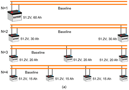
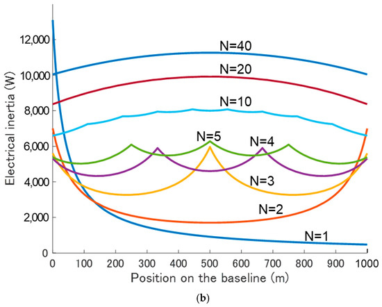
Figure 5.
Calculation of electrical inertia for number of battery divisions N: (a) divided battery placement on the baseline; (b) calculated electrical inertia on the baseline.
The magnitude of electrical inertia in DC microgrids directly connected to the baseline is determined by the internal resistance of the batteries used and is not directly related to battery capacity. However, the value of internal resistance of the batteries is inversely proportional to battery capacity. The discharge response speed of batteries varies depending on the type of battery, but in the case of lithium-ion batteries, it is less than a few microseconds. Therefore, since power transmission through power lines occurs at nearly the speed of light, electrical inertia reaches the power load within a few microseconds after switching on the equipment. However, when a DC/DC converter for voltage conversion is used between the batteries and the baseline, the response speed slows to several milliseconds or more due to the electrical control of the DC/DC converter, and the maximum power is further limited by output devices, which may prevent the inherent electrical inertia of the batteries from being fully transmitted to the baseline. This is the primary reason for directly connecting batteries to the baseline.
6. Spontaneous Equalization of Each Battery SoC
In the proposed battery direct-connected DC grid, distributed batteries with the same terminal voltage are connected by a single baseline, so even if there is a temporary difference in terminal voltage, it will equalize over time. This has been demonstrated by my testbed and will be discussed in Section 9. In this case, the terminal voltage of the battery reflects the battery’s SoC, assuming that the terminal voltage of a battery with a higher SoC is high than that of a battery with a lower SoC. This is generally the relationship in typical batteries. As a simple calculation, if a potential difference of 1 V occurs between adjacent batteries, and the electrical resistance of the baseline connecting the batteries is 0.1 Ω (corresponding to the conductor resistance of a 100 m length of 14 SG CV cable), if the baseline voltage is 400 V, 2 kW of power will flow from the battery with a higher terminal voltage to the one with a lower terminal voltage. This results in the spontaneous equalization of the SoC.
In typical microgrids, the SoC of each distributed battery is monitored by a controller installed somewhere, and if there is an imbalance in the SoC between batteries, the controller commands the DC/DC converter connected to the battery to artificially equalize the SoC. When directly connecting batteries to the baseline, such operations are unnecessary for SoC equalization.
This spontaneous SoC equalization by direct connection to the baseline is independent of the capacity of the distributed batteries. Therefore, even if batteries with different capacities are connected to the baseline, spontaneous equalization of SoC occurs for all batteries. Furthermore, even if the batteries are degraded, the typical battery degradation mode only increases internal resistance and does not significantly change the electromotive force value, so there is no significant problem even with slightly degraded batteries.
7. Locality of Autonomous Decentralized Control and a Weakly Coupled Grid
Autonomous distributed control is a method in which each device using the grid controls autonomously, so the control must be localized. In other words, the control of one device should not extend to neighboring devices, and there should be no interference between their controls. For example, a charge controller is used to charge the battery with power generated by solar panels. The charge controller monitors the terminal voltage of the battery being controlled and decides whether to charge or stop charging based on that terminal voltage. Therefore, as shown in Figure 6a, when a single charge controller controls the charging of each battery, this allows for the proper use of the charge controller and poses no problem. However, in this case, the batteries are not connected by power lines, so they are in ’island mode’ and no power exchange occurs between them.
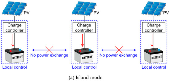
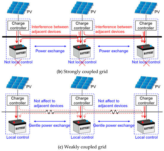
Figure 6.
Differences in charging control methods depending on the strength of electrical coupling between batteries: (a) island mode; (b) strongly coupled grid; (c) weakly coupled DC grid.
However, as shown in Figure 6b, when batteries are directly connected to the baseline, they may be affected by the terminal voltage of adjacent directly connected batteries, leading to incorrect charging control as the charge controller cannot accurately grasp the terminal voltage of the intended battery. Similarly, the charge control might extend to adjacent batteries, causing them to be charged as well. Thus, to achieve ADCC, the control must be localized and should not affect neighboring devices. To prevent this, I propose a ‘weakly coupled grid’ (Figure 6c) with weak electrical coupling between devices connected to the grid.
In existing power grids, generators at power plants, transformers at substations, and power loads at consumers are electrically strongly coupled, forming a tightly coupled grid. Consequently, the baseline voltage is considered constant everywhere, and centralized control is performed. In contrast, my proposed battery directly connected to the DC grid requires a loosely coupled condition where each device is electrically weakly coupled. The strength of the electrical coupling between each device is an indicator of the capacity of the power lines connecting those devices, relative to the rated power of each device (generation power for generators, charge/discharge power for batteries, and consumption power for power loads). Therefore, the lower the electrical resistance of the power lines connecting the devices, the higher the voltage, and the larger the allowable current, the stronger the coupling. As a result, the weakly coupled grid I propose, allowing for a small deviation of the baseline voltage to which each device is connected, even if they are connected by a single baseline. Having devices weakly coupled electrically means each device can maintain the independence of ADCC in the short term while allowing for relatively slow power exchange between devices in the long term.
8. Grid Configuration and Safety Measure
The method of configuring DC baselines with distributed and directly connected batteries is shown in Figure 7. In this configuration, small batteries are distributed and directly connected to the positive and negative baselines, with the midpoint of those batteries grounded. For example, in the case of a baseline voltage of about 50 V, two batteries with an equal terminal voltage of 25 V are connected in series, and the midpoint is grounded. This enhances resistance to lightning strikes and electromagnetic pulse (EMP) attacks and ensures safety against leakage currents. Power generation equipment such as solar panels and power load devices is connected to the positive and negative lines of the baseline to send or receive power. Therefore, if there is no ground fault causing leakage on one of the baseline lines, the same magnitude of current flows in the opposite direction in the positive and negative lines, preventing any external leakage magnetic field. Additionally, if a ground fault occurs, the imbalance in current flow between the positive and negative lines can be easily detected by a clamp-type leakage detector or similar device.
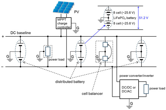
Figure 7.
Configuration of the DC baseline.
In this setup, the two lines of the baseline are fixed at +25 V and −25 V with respect to the ground potential, so in the unlikely event of electric shock due to leakage, the voltage shock will not exceed this value. Of course, if both poles of the baseline are touched, one will experience the full 50 V baseline voltage.
In the event of a direct lightning strike on the baseline, a momentary high voltage will occur, possibly damaging storage batteries and equipment near the strike point. However, the damaged storage batteries could serve as a fuse, potentially protecting other equipment. In the case of induced lightning, the directly connected storage batteries function as large capacitors, absorbing the surge current caused by the lightning. Similarly, the effects of magnetic storms or EMP attacks are mitigated due to this function.
Since the same magnitude of current flows in both the positive and negative lines of the baseline, the positive and negative sides of the directly connected batteries always maintain the same SoC and an equal voltage magnitude with opposite polarity relative to the midpoint. To correct any imbalance, a cell balancer with correction capabilities is desirable [38,39].
When directly connecting batteries to the baseline, it is necessary to match the terminal voltage to the baseline voltage. This is not particularly difficult since various types of batteries with different terminal voltages are widely available in the market. The LiFePO4 batteries used in my constructed microgrid have a cell voltage of 3.2 V, with many commercially available options of 25.6 V (8 cells in series) or 51.2 V (16 cells in series). Therefore, as shown in the figure, by connecting these in series, storage batteries that correspond to baseline voltages of 50 V or 400 V can be configured.
In the proposed DC grid, which is characterized by the distribution and direct connection of batteries to the baseline to provide electrical inertia, safety measures are indispensable because large currents flow during ground faults or short circuits in the baseline, potentially leading to major accidents [40,41]. Of course, existing AC power grids are also equipped with circuit breakers (CBs) and fuses in various locations to prepare for such accidents. While existing ultra-high voltage circuits in power grids require special CBs to cut the arc discharge that occurs during circuit disconnection, the DC microgrid envisioned here has a baseline voltage of around several hundred volts, so such special CBs are not considered necessary. However, since many commercially available CBs are for AC use, CBs that can be used with DC are required. When a short circuit or ground fault occurs in the baseline, an abnormal large current flows momentarily. The mechanism to detect this and cut the circuit is the same as existing ones, but a considerably large current capacity (hundreds of amperes) and rapid response are required.
As an example, various safety measures for the DC grid with a baseline voltage of 400 V are shown in Figure 8. By installing overcurrent CBs that detect and cut overcurrent at various locations in the baseline, the shorted section can be isolated on both sides from the baseline, preventing accident escalation. In this way, the installation of overcurrent CBs along the baseline is feasible only in weakly coupled grids. In contrast, in strongly coupled existing grids, it is uncommon to install overcurrent CBs in the middle of transmission or distribution lines.
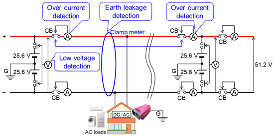
Figure 8.
Safety measures for microgrids.
At the very least, as shown in the figure, overcurrent CBs should be installed at all connection points between the distributed batteries and the baseline. In my constructed microgrid, 63 A CBs are installed between each battery and the baseline. Therefore, it is possible to replace each battery (hot swap) without stopping the grid, and CBs are also installed between each power box and the baseline, allowing each power box to be freely connected or disconnected from the baseline.
Furthermore, when a short circuit or ground fault occurs in the baseline, a large discharge current occurs from the batteries directly connected to the nearby baseline, leading to an abnormal drop in terminal voltage. Therefore, it is also effective to install abnormal voltage CBs that detect and cut the circuit upon detecting an abnormal battery terminal voltage. This is also effective for protecting batteries from overcharging or over-discharging. Some lithium-ion batteries are equipped with a BMS function that disconnects from the terminals to protect the battery when the terminal voltage drops below a specified value.
On the other hand, ground fault accidents can be addressed with a breaker based on the same principle as commercially available AC residual current devices (RCDs). In a neutral point grounded DC baseline with the baseline voltage’s neutral point grounded as shown in the figure, the magnitude of current flowing in the positive and negative sides of the baseline should normally be equal, but if a ground fault occurs somewhere, this becomes unbalanced and can be detected by a conventional clamp meter or RCD. Therefore, countermeasures can be taken by installing such devices at various locations along the baseline.
9. Demonstration Experiment
To verify the feasibility of the battery directly connected DC microgrid, I constructed a testbed of the microgrid on my university campus, as shown in Figure 9. Power boxes, which house LiFePO4 batteries with a rated terminal voltage of 51.2 V, are installed on the rooftops of four school buildings, namely Buildings 1–4 (B1–B4). These are connected by a power baseline made up of 14 SQ CV cables. Additionally, 800 W solar panels are installed on the rooftops of Buildings 1–3 (B1–B3) and connected to the batteries within each power box through MPPT charge controllers. The baseline is laid in a T-shape with Building 4 (B4) serving as a hub and Buildings 1–3 (B1–B3) being the endpoints of the baseline. The B4 hub is equipped with a battery with double the capacity (240 Ah) compared to the batteries in B1–B3, although it does not have solar panels installed.
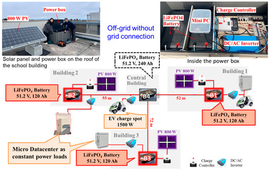
Figure 9.
Testbed of the battery directly connected DC microgrids.
The reason for installing the power boxes outdoors on the rooftops of school buildings is to mitigate the risk of fire from lithium-ion batteries, to comply with fire safety regulations, and to prepare for future replacements of existing power distribution grids with DC systems, wherein distributed storage batteries are envisioned to be installed at pole transformer locations. Consequently, the power boxes are waterproofed, lined with insulation on the inside, and further covered with a silver sheet. The batteries have shown no significant damage or degradation even though the outdoor temperatures can drop below freezing in winter and exceed 40 °C during summer days. The power boxes also contain MPPT charge controllers, DC/AC inverters, mini-PCs for monitoring, and switching hubs for wired network links, all of which have been installed for over three years and continue to function normally.
This microgrid operates off-grid (island mode), entirely powered by renewable energy (solar power). The power loads consist of distributed micro-datacenters installed on the rooftops of buildings B1–B3, which consume approximately 100 W of power on a regular basis, and electric vehicle (EV) charging spots. When the baseline voltage is sufficiently high, the EVs are occasionally charged. Table 1 shows the specifications of the microgrid.

Table 1.
The specifications of the constructed DC microgrid.
The devices connected to this grid operate autonomously in a distributed cooperative manner without exchanging information via communication lines. For example, the charge controller of the solar panel performs MPPT control when the terminal voltage of the connected battery is 56 V or lower. However, when it seems likely to exceed 56 V, it switches to float mode to maintain 55.6 V, to prevent overcharging or battery damage.
Additionally, when the battery terminal voltage drops below 51 V, a low-voltage alarm is sent to the administrator via email, leading to manual suppression of power load usage. If the battery voltage continues to drop further, the battery management system (BMS) within the battery stops output to the terminals to prevent over-discharge damage. As an off-grid power source, this microgrid handles such situations by disconnecting power loads before reaching this final measure. Therefore, the baseline voltage fluctuates within the range of 51 V to 56 V even during normal operation, requiring power loads to be designed to operate within this voltage range. In practice, the DC/AC converters used in the system can operate within this voltage range. (For reference, the voltage range of Japan’s household 100 V indoor wiring is regulated by Article 38 of the Electricity Business Act Enforcement Regulations to be within the range of 95 to 107 V, not exceeding ±6 V of 101 V).
In this grid, each device connected to the grid is required to comply with the grid usage rule (Grid Code) regarding the baseline voltage, which is to operate within the range of 51 V to 56 V. Therefore, each device autonomously controls its operation to avoid deviating from that range. For example, if the baseline voltage is close to the upper limit of 56 V, and further power supply might exceed the appropriate range, solar power generators will refrain from supplying power, even if they have the potential to generate it. Similarly, if the baseline voltage is close to the lower limit of 51 V, and further power consumption might fall below the appropriate range, the load will not start operating.
Such an ADCC grid might appear imperfect due to its limitations in overall optimization. However, output suppression of renewable energy power generation in existing grids is already common. The critical point is to minimize the frequency of such occurrences. The grid should be designed to ensure that these events are exceedingly rare. In addition, since the batteries of each power box are directly connected to the baseline, any voltage difference at the terminal voltage will naturally be equalized through power exchange via the baseline.
The charge controllers for solar panels are USB-connected to the mini-PCs within the power boxes, and through a wired LAN laid along the power baseline, the generated power, charging power, temperature inside the box, etc., can be monitored in real-time. This setup is solely for monitoring purposes and does not involve any specific control. Figure 10 shows the monitoring screen of the microgrid, allowing monitoring at 1 s intervals for the battery terminal voltage, and at 1 min intervals for the battery temperature, solar panel generation power, power consumption of the connected loads, etc.
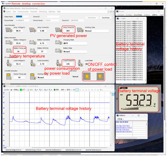
Figure 10.
Monitor screen of the microgrid operation.
The LiFePO4 batteries used in my microgrid are configured with 16 series-connected and 12 parallel-connected 26,650 cells (3.2 V, 3.3 Ah). The relationship between the terminal voltage and SoC (approximate) at no load is estimated as shown in Figure 11. Therefore, the SoC of the batteries near the measurement point of the baseline can be roughly estimated from the baseline voltage. This means that each device connected to the baseline can understand the power situation (the SoC of the distributed battery) around it by sensing the baseline voltage.
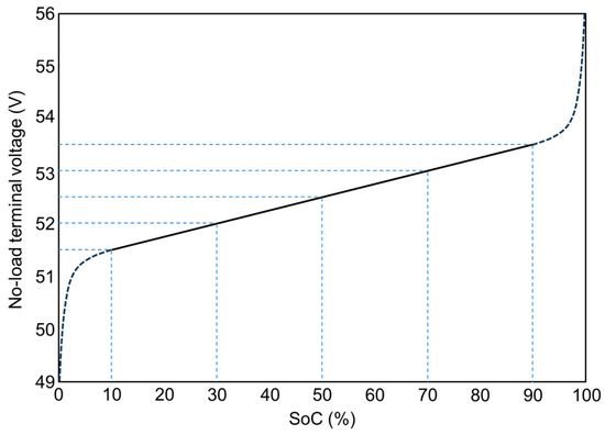
Figure 11.
Relationship between battery terminal voltage and SoC.
Figure 12 shows the time variations in solar power generation and battery terminal voltage (equal to the baseline voltage at that point) at B1, B2, and B3 measured over the course of one month, January 2023 [42]. Multiple solar panels are connected to each battery via charge controllers; however, due to the moderate conductor resistance of the CV cables between each battery, they are loosely coupled, ensuring the independence of each charge controller’s regulation. Each device autonomously adheres to the grid regulations, resulting in the battery terminal voltage of each power box ranging from 51 to 56 V. Consequently, even if temporary discrepancies occur due to activities such as EV charging, the terminal voltage of each battery naturally equalizes over time.
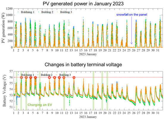
Figure 12.
System operation record for one month, January 2023.
In this microgrid, multiple small batteries are directly connected to the baseline, and voltage is always applied to the baseline, allowing for instantaneous power extraction from any point on the baseline. Furthermore, the power supply to the load is coordinated by multiple batteries in the vicinity, distributing the power load across multiple batteries (coordinated power supply). To demonstrate this, an experiment was conducted on a sunny day, 14 April 2023, from 9:40 A.M. to 11:00 A.M., where power was artificially extracted from the B4 power box using an electronic load device.
Figure 13 shows the graphs of (a) solar power generation, (b) the terminal voltage of each battery, and (c) the inflow and outflow current of the B4 power box over time, as recorded during that period. The three buildings, B1 to B3, where the solar panels are installed are adjacent to each other and all have the same rated (800 W) solar panels, resulting in similar solar power generation, as shown in Figure 13a. At the start of the measurement period, the batteries in B1 to B3 were receiving 550–600 W of generated power from each solar panel. The terminal voltage of the batteries in B1 and B3 was high, at around 54 V. On the other hand, the batteries in B4, which did not have solar panels, and B2, which consumed power due to the micro-datacenter, had slightly lower voltages (Figure 13b).
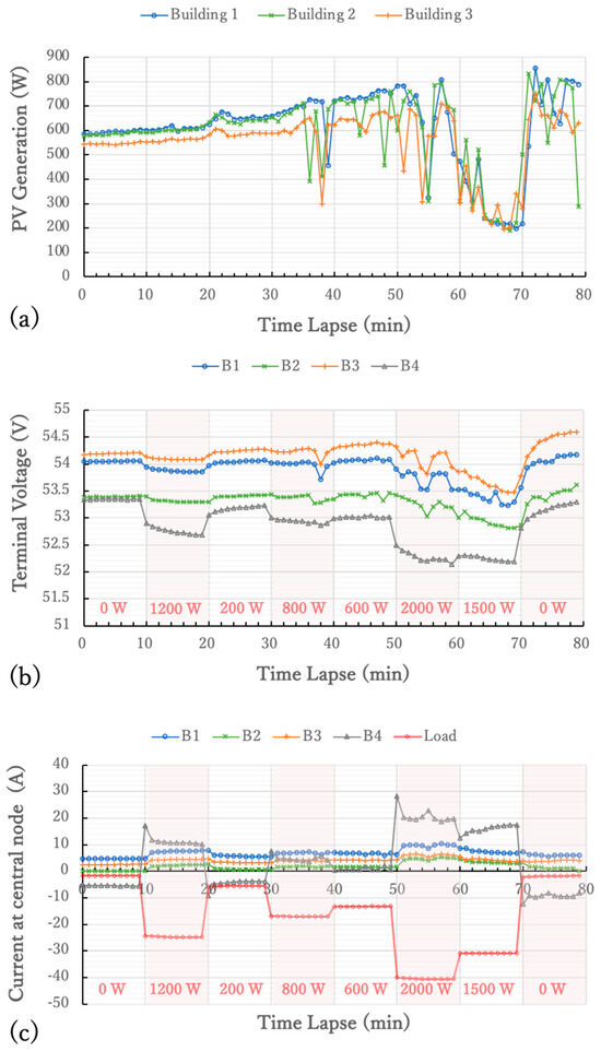
Figure 13.
Graph of time change in power load experiment: (a) solar power generation, (b) terminal voltage of each battery, and (c) inflow and outflow current of the B4 power box over time.
In the experiment, the power consumption of the electronic load device connected to B4 was switched every 10 min in the following order: 0 W, 1200 W, 200 W, 800 W, 600 W, 2000 W, 1500 W, and 0 W. Figure 13c shows that a large current was discharged from the B4 battery, directly connected to the electronic load. In the graph, the positive values on the vertical axis for B1 to B4 represent discharging from each battery, and the negative values represent charging to each battery. At the beginning of the experiment, B4’s battery was being charged by the batteries in B1 and B3. The graph indicates that when a large load, such as 2 kW, was connected, the nearby batteries coordinated to supply power (coordinated power supply), supporting the validity of droop control by the battery itself.
In coordinated power supply, the distribution ratio of power supply from each battery is determined solely by the voltage difference at the terminals of each battery and the electrical resistance of the power lines connecting them. Figure 14a shows the simplified equivalent circuit of the baseline and batteries in my DC microgrid. Each battery is represented by a DC voltage source corresponding to its electromotive force and internal resistance, while the baseline cables are modeled as electrical resistances with lumped constants representing their conductor resistance. V1 to V4 and r1 to r4 represent the electromotive force of each battery (with variations depending on their SoC) and their internal resistance, while R1 to R3 mainly represent the conductor resistance of the baseline cables connecting the batteries, and R4 represents contact resistances such as terminal connections. Table 2 shows measured parameter values of the equivalent circuit for my microgrid. Based on this equivalent circuit, the voltage at each node and the current flowing through each branch can be easily calculated using DC circuit theory. Figure 14b compares the measured baseline currents I1 to I4 at B4 with their calculations with the simplified equivalent circuit model, and the two align closely. This demonstrates that the state of the grid can be accurately described using such a simple equivalent circuit model and straightforward calculations, which is one of the features of a battery directly connected DC grid.
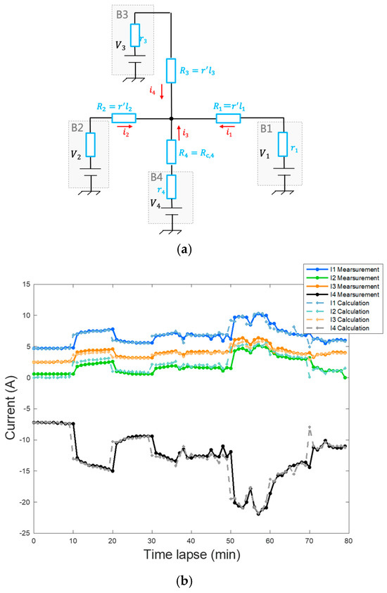
Figure 14.
(a) Simplified equivalent circuit of the baseline and batteries in my DC microgrid, (b) measured baseline currents I1 to I4 at B4 and calculations with the simplified equivalent circuit model.
Table 2.
Measured parameter values of the equivalent circuit for my microgrid.
In this grid, the baseline has a large electrical inertia, so that a large amount of power can be always extracted from any point on the baseline. Next, experiments applying power loads to the batteries on B1 to B3 were conducted to investigate the power supply distribution ratio from each battery in response to the applied loads.
Figure 15 illustrates the power supplied by each battery, including the newly measured results for B4, with different colors used to indicate the contributions. Positive values on the vertical axis represent the discharge power of the batteries, while negative values indicate charging power. During the experiments, solar generated power also flowed into the batteries at the nodes B1 to B3, so the power generation needed to be subtracted to calculate the applied load values. Consequently, the red line labeled “Net Demand” represents the net load power after subtracting the solar power generation. A negative value for this line indicates that the solar power generation exceeded the applied load power. From Figure 15, it can be observed that the battery connected to the applied load naturally had the highest contribution ratio. However, nearby batteries also shared a substantial portion of the load, demonstrating the effectiveness of coordinated power supply.
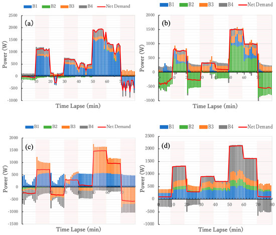
Figure 15.
Power supply distribution of each battery when the power load is connected to (a) B1, (b) B2, (c) B3, and (d) B4.
Finally, I would like to mention the disaster resilience of this microgrid. The greatest feature of the weakly coupled ADCC DC grid is that even if a part of the baseline is cut and the grid is split into two, the two separated grids can continue to function normally as independent ADCC grids. In my testbed, CBs are installed between each power box and the baseline, and it has been confirmed that there is no change in the grid when they are disconnected at any moment. The two grids that are separated can both continue to operate normally. Additionally, if the baseline voltages of the two grids are almost equal, they can be reconnected to form a single grid again. In other words, the grid can be disconnected and reconnected at any time with a single touch, which also underscores its strong disaster resilience.
10. Interconnection with Existing Power Grid
In microgrids that rely primarily on unstable renewable energy power generation, stable power supply remains a significant challenge. Conversely, existing power grid systems are vulnerable to natural disasters and face destabilization issues as the integration of renewable energy progresses. By interconnecting with existing power grid systems, I aim to cover the shortcomings of both systems, achieving a green, resilient, and stable power supply.
Figure 16 illustrates the method of interconnection between both grids. Within distributed regional microgrids, the goal is to utilize locally generated renewable energy, such as small-scale solar, wind, and hydroelectric power, to the fullest extent, while maintaining power supply through the provision of engine-driven emergency power sources in case of power shortages. However, equipping each microgrid with its own emergency power source is not efficient. By interconnecting with existing power grid systems, power can be received from the grid during shortages. Therefore, while each microgrid aims for partial optimization of power distribution through ADCC, the existing power grid system aims for overall optimization by equalizing power distribution among microgrids. This division of roles leverages the strengths of both microgrids and existing power grid systems. In this case, short-term and small-scale power fluctuations are addressed by the electrical inertia within each microgrid (momentary response), while long-term and large-scale fluctuations are addressed by power supply from the grid (sustained response).
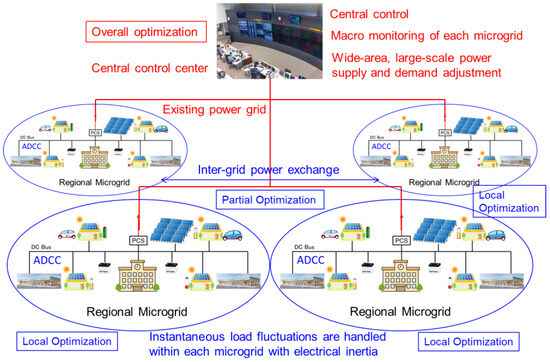
Figure 16.
Interconnection with existing power grid.
Interconnection with the existing power grid also enables power exchange between microgrids. If renewable energy generation within a microgrid exceeds consumption and storage batteries become fully charged, off-grid systems will have to halt power generation. However, with interconnection, surplus power can be fed back into the grid and utilized by microgrids experiencing power shortages, thereby effectively utilizing the renewable energy potential without waste. Utilizing the existing power grid allows for wide-area power exchange and realizes overall optimization of power distribution.
11. Conclusions
This paper proposes a novel approach for constructing a DC grid by directly connecting small batteries along the DC bus in a distributed manner and introduces a method for achieving autonomous decentralized cooperative control (ADCC).
Conventional DC grid systems have treated the DC baseline, which is situated at the lowest physical layer of the grid’s system hierarchy, as mere wiring for power exchange among devices. Consequently, essential grid-stabilizing functions such as electrical inertia and droop control for coordinated operation between distributed power sources were implemented within the upper control layer via DC/DC converters with pseudo-inertia or configured droop parameters. In contrast, the battery-integrated DC baseline proposed herein is not just a passive conductor but serves as a “functional powerline” by endowing it with electrical inertia and enabling functions such as coordinated power supply and distribution balancing among connected batteries. This was realized by leveraging the intrinsic droop characteristics of batteries. By directly connecting batteries to the baseline, their inherent droop properties were utilized to achieve coordinated operation among distributed batteries without relying on DC/DC converters. Additionally, this architecture allows for significant electrical inertia to permeate throughout the grid, contributing to grid stability. Furthermore, spontaneous power exchange among batteries directly connected to the baseline naturally resolves temporary imbalances in state of charge (SoC) over time.
We also explored the ADCC method tailored for DC grids employing this battery-integrated baseline. For ADCC to be realized, it is crucial for each device connected to the grid to grasp the state of the grid. Unlike centralized control, it is difficult for individual devices to have a comprehensive understanding of the state of the entire grid, but they can have some understanding of the state of the grid in their own neighborhood. In the proposed architecture, the SoCs of nearby batteries are reflected in the baseline voltage. This enables individual devices to infer the local grid state (e.g., power conditions) from the baseline voltage. Moreover, maintaining the independence of each device’s control is imperative, for which methods to ensure the locality of device control were examined. I identified that weak electrical coupling among devices connected to the baseline is essential to achieving ADCC. In other words, electrical control should not extend beyond adjacent devices, while still allowing for gradual power exchange over the long term, necessitating an appropriate coupling strength.
To validate the feasibility of this approach, a DC microgrid testbed with battery-integrated baselines was constructed on a university campus, and the fluctuations of photovoltaic (PV) generation and baseline voltage were monitored over a one-month period. The results confirmed the locality of PV charging control for individual distributed batteries, demonstrating that PV charge controllers accurately regulated only their respective batteries. Consequently, the baseline voltage was maintained within the optimal range of 51–56 V, and temporary SoC imbalances caused by electric vehicle (EV) charging naturally equalized over time. Furthermore, experiments with electronic loads at various baseline points confirmed the coordinated operation of distributed batteries near the loads, effectively supplying power collaboratively.
While numerous advantages of the proposed architecture have been demonstrated, challenges remain. Firstly, the terminal voltage of batteries directly connected to the baseline must match the baseline voltage within a certain range. Preparing enough of such batteries is a potential issue. My testbed was small, and I built a baseline to fit 10 available batteries with terminal voltages of 51.2 V. Whether suitable batteries are widely available for the commonly utilized baseline voltage range of 350–400 V remains uncertain. Additionally, my testbed utilized new batteries in experiments spanning less than three years. Long-term issues related to battery degradation over 10 or 20 years warrant further investigation.
Safety concerns also present a challenge. While direct connecting batteries provide significant electrical inertia, they also pose risks, such as substantial current flow from nearby batteries in the event of a short circuit or ground fault. Although safety measures were incorporated into my testbed, and no accidents occurred during testing, the effectiveness of these measures under actual fault conditions remains to be confirmed.
Despite these challenges, the biggest feature of this method is that it delegates basic grid-operating functions such as electrical inertia and power distribution balancing, which were conventionally handled by the higher-level control layer, to the physical layer of the baseline. This approach alleviates the burden on the control layer, allowing it to focus on more advanced and efficient operations. By integrating the proposed “functional powerline” into existing DC grids to form a composite system, basic control tasks such as grid stabilization and power distribution balancing can be managed at the baseline level. Consequently, the higher control layers and application layers of the grid system can be dedicated to more sophisticated applications, including energy management systems (EMSs) or power trading, facilitating the development of application-centric systems.
The proposed ADCC-based DC microgrid demonstrates resilience, as even in cases of partial system failure, the remaining components can maintain functionality to some extent. This characteristic makes it particularly suitable for residential areas in disaster-prone regions. Equipping individual households with small batteries interconnected via weak DC baselines will enable sharing of locally generated power, such as solar energy, among neighboring households—potentially paving the way toward a resilient and community-based power infrastructure.
Funding
This research was funded by the JST OPERA Prog. (Grant Number JPMJOP1852).
Data Availability Statement
The original contributions presented in this study are included in the article. Further inquiries can be directed to the corresponding author.
Acknowledgments
The author would like to extend a special thanks to Liu Ke, who was a student in the author’s laboratory. Part of the content of this paper is based on the research conducted as part of her thesis under the guidance of the author. Additionally, through the JST OPERA project, the author had many valuable discussions with K. Iwatsuki and T. Otsuji. The author would like to express deep gratitude to them once again.
Conflicts of Interest
The author declares no conflicts of interest. The funders had no role in the design of this study; in the collection, analyses, or interpretation of data; in the writing of the manuscript; or in the decision to publish the results.
Abbreviations
The following abbreviations are used in this manuscript:
| AC | alternating current |
| ADCC | autonomous decentralized cooperative control |
| BMS | battery management system |
| CB | circuit breaker |
| CO2 | carbon dioxide |
| CV | cross-linked polyethylene insulation vinyl sheath |
| DC | direct current |
| EMP | electromagnetic pulse |
| EV | electric vehicle |
| LAN | local area network |
| MPPT | maximum power-point tracking |
| PC | personal computer |
| PV | photovoltaic (solar cell) |
| RCD | residual current device |
| SoC | state of charge for batteries |
| SQ | square meters |
| USB | universal serial bus |
References
- Marnay, C.; Xu, T.; Hatziargyriou, N.D.; Hirase, Y.; Mendoza-Araya, P. Microgrids 2023 editorial. Appl. Energy 2023, 352, 121981. [Google Scholar] [CrossRef]
- Uddin, M.; Mo, H.; Dong, D.; Elsawah, S.; Zhu, J.; Guerrero, J.M. Microgrids: A review, outstanding issue and future trends. Energy Storage Rev. 2023, 49, 101127. [Google Scholar] [CrossRef]
- Punitha, S.; Subramaniam, N.P.; Vimal Raj, P.; Ajay, D. A comprehensive review of microgrid challenges in architectures, mitigation approaches, and future directions. J. Electr. Syst. Inf. Technol. 2024, 11, 60. [Google Scholar] [CrossRef]
- Miyamoto, Y.; Hasegawa, M.; Kyoto, T. Isumi-City regional micro-grid current situation. Jpn. Sol. Energy Soc. JSES Conf. 2024, 31–32. (In Japanese) [Google Scholar] [CrossRef]
- Regional Microgrids Program in Australia, Australian Government Australian Renewable Energy Agency. Available online: https://arena.gov.au/funding/rmp/ (accessed on 2 March 2025).
- Elsayed, A.T.; Mohamed, A.A.; Mohammed, O.A. DC microgrids and distribution systems: An overview. Electr. Power Syst. Res. 2015, 119, 407–417. [Google Scholar] [CrossRef]
- Dragičević, T.; Lu, X.; Vasquez, J.C.; Guerrero, J.M. DC Microgrids—Part I: A Review of Control Strategies and Stabilization Techniques. IEEE Trans. Power Electron. 2015, 31, 4876–4891. [Google Scholar] [CrossRef]
- Dragičević, T.; Lu, X.; Vasquez, J.C.; Guerrero, J.M. DC Microgrids—Part II: A Review of Power Architectures, Applications, and Standardization Issues. IEEE Trans. Power Electron. 2016, 31, 3528–3549. [Google Scholar] [CrossRef]
- Kumara, J.; Agarwal, A.; Singh, N. Design, operation and control of a vast DC microgrid for integration of renewable energy sources. Renew. Energy Focus 2020, 34, 17–36. [Google Scholar] [CrossRef]
- Al-Ismail, F.S. DC Microgrid Planning, Operation, and Control: A Comprehensive Review. IEEE Access 2021, 9, 36154–36172. [Google Scholar] [CrossRef]
- Rangarajan, S.S.; Raman, R.; Singh, A.; Shiva, C.K.; Kumar, R.; Sadhu, P.K.; Collins, E.R.; Senjyu, T. DC Microgrids: A Propitious Smart Grid Paradigm for Smart Cities. Smart Cities 2023, 6, 1690–1718. [Google Scholar] [CrossRef]
- Lidula, N.W.A.; Rajapakse, A.D. Microgrids research: A review of experimental microgrids and test systems. Renew. Sustain. Energy Rev. 2011, 15, 186–202. [Google Scholar] [CrossRef]
- Hossain, E.; Kabalci, E.; Bayindir, R.; Perez, R. Microgrid testbeds around the world: State of art. Energy Convers. Manag. 2014, 86, 132–153. [Google Scholar] [CrossRef]
- Cagnano, A.; Tuglie, D.E.; Mancarella, P. Microgrids: Overview and guidelines for practical implementations and operation. Appl. Energy 2020, 258, 114039. [Google Scholar] [CrossRef]
- Cañizares, C.A.; Palma-Behnke, R.; Olivares, D.E.; Mehrizi-Sani, A.; Etemadi, A.H.; Iravani, R.; Kazerani, M.; Hajimiragha, A.H.; Gomis-Bellmunt, O.; Saeedifard, M.; et al. Trends in Microgrid Control. IEEE Trans. Smart Grid 2014, 5, 1905–1919. [Google Scholar] [CrossRef]
- Meng, L.; Shafiee, Q.; Trecate, G.F.; Karimi, H.; Fulwani, D.; Lu, X.; Guerrero, J.M. Review on Control of DC Microgrids and Multiple Microgrid Clusters. IEEE J. Emerg. Sel. Top. Power Electron. 2017, 5, 928–948. [Google Scholar] [CrossRef]
- Kuma, J.; Agarwal, A.; Agarwal, V. A review on overall control of DC microgrids. J. Energy Storage 2019, 21, 113–138. [Google Scholar] [CrossRef]
- Papadimitriou, C.N.; Zountouridou, E.I.; Hatziargyriou, N.D. Review of hierarchical control in DC microgrids. Electr. Power Syst. Res. 2015, 122, 159–167. [Google Scholar] [CrossRef]
- Guerrero, J.M.; Vasquez, J.C.; Matas, J.; García de Vicuña, L.; Castilla, M. Hierarchical Control of Droop-Controlled AC and DC Microgrids—A General Approach Toward Standardization. IEEE Trans. Ind. Electron. 2011, 58, 158–172. [Google Scholar] [CrossRef]
- Wang, C.J.P.; Xiao, J.; Tang, Y.; Choo, F.H. Implementation of Hierarchical Control in DC Microgrids. IEEE Trans. Ind. Electron. 2014, 61, 4032–4042. [Google Scholar] [CrossRef]
- Shuai, Z.; Fang, J.; Ning, F.; Shen, Z.J. Hierarchical structure and bus voltage control of DC microgrid. Renew. Sustain. Energy Rev. 2018, 82, 3670–3682. [Google Scholar] [CrossRef]
- Kaur, A.; Kaushal, J.; Basak, P. A review on microgrid central controller. Renew. Sustain. Energy Rev. 2016, 55, 338–345. [Google Scholar] [CrossRef]
- Wang, B.; Sechilariu, M.; Locment, F. Intelligent DC Microgrid with Smart Grid Communications: Control Strategy Consideration and Design. IEEE Trans. Smart Grid 2012, 3, 1248–2156. [Google Scholar] [CrossRef]
- Saleh, M.; Esa, Y.; Mohamed, A.A. Communication-Based Control for DC Microgrids. IEEE Trans. Smart Grid 2019, 10, 2180–2195. [Google Scholar] [CrossRef]
- Mehdi, M.; Kim, C.-H.; Saad, M. Robust Centralized Control for DC Islanded Microgrid Considering Communication Network Delay. IEEE Access 2020, 8, 77765–77778. [Google Scholar] [CrossRef]
- Azizi, A.; Peyghami, S.; Mokhtari, H.; Blaabjerg, F. Autonomous and decentralized load sharing and energy management approach for DC microgrids. Electr. Power Syst. Res. 2019, 177, 106009. [Google Scholar] [CrossRef]
- Farshad, A. Autonomous DC Microgrid with Self-Configurable Feasibility. Master’s Thesis, Michigan Technological University, Houghton, MI, USA, 2016. [Google Scholar] [CrossRef]
- Yoshida, N.; Kikuchi, A.; Shimada, T.; Ide, K. Autonomous Decentralized DC Bus Voltage Control using DC Multi Power Units in DC Microgrid Applications. IEEJ Trans. Ind. Appl. 2023, 143, 564–569. [Google Scholar] [CrossRef]
- Chen, D.; Xu, L. Autonomous DC Voltage Control of a DC Microgrid with Multiple Slack Terminals. IEEE Trans. Power Syst. 2012, 27, 1897–1905. [Google Scholar] [CrossRef]
- Chen, D.; Xu, L.; Yao, L. DC Voltage Variation Based Autonomous Control of DC Microgrids. IEEE Trans. Power Deliv. 2013, 28, 637–648. [Google Scholar] [CrossRef]
- Vijayaragavan, R.; Umamaheswari, B. Decentralized control of autonomous DC microgrids with composite loads: An approach using optimal control. Electr. Eng. 2021, 103, 2871–2885. [Google Scholar] [CrossRef]
- Richard, L.; Boudinet, C.; Ranaivoson, S.A.; Rabarivao, J.O.; Befeno, A.E.; Frey, D.; Alvarez-Hérault, M.-C.; Raison, B.; Saincy, N. Development of a DC Microgrid with Decentralized Production and Storage: From the Lab to Field Deployment in Rural Africa. Energies 2022, 15, 6727. [Google Scholar] [CrossRef]
- Lu, X.; Guerrero, J.M.; Sun, K.; Vasquez, J.C. An Improved Droop Control Method for DC Microgrids Based on Low Bandwidth Communication with DC Bus Voltage Restoration and Enhanced Current Sharing Accuracy. IEEE Trans. Power Electron. 2014, 29, 1800–1812. [Google Scholar] [CrossRef]
- Peyghami, S.; Mokhtari, H.; Loh, P.C.; Davari, P.; Blaabjerg, F. Distributed Primary and Secondary Power Sharing in a Droop-Controlled LVDC Microgrid with Merged AC and DC Characteristics. IEEE Trans. Smart Grid 2018, 9, 2284–2294. [Google Scholar] [CrossRef]
- Dragicevi, T.; Guerrero, J.M.; Vasquez, J.C.; Skrlec, D. Supervisory Control of an Adaptive-Droop Regulated DC Microgrid With Battery Management Capability. IEEE Trans. Power Electron. 2014, 29, 695–706. [Google Scholar] [CrossRef]
- Zhu, X.; Meng, F.; Xie, Z.; Yue, Y. An Inertia and Damping Control Method of DC–DC Converter in DC Microgrids. IEEE Trans. Energy Convers. 2020, 35, 799–807. [Google Scholar] [CrossRef]
- Wu, W.; Chen, Y.; Luo, A.; Zhou, L.; Zhou, X.; Yang, L.; Dong, Y.; Guerrero, J.M. A Virtual Inertia Control Strategy for DC Microgrids Analogized with Virtual Synchronous Machines. IEEE Trans. Ind. Electron. 2017, 64, 6005–6016. [Google Scholar] [CrossRef]
- Chowdhury, S.; Shaheed, M.N.B.; Sozer, Y. State-of-Charge Balancing Control for Modular Battery System with Output DC Bus Regulation. IEEE Trans. Transp. Electrif. 2021, 7, 2181–2193. [Google Scholar] [CrossRef]
- Lu, X.; Sun, K.; Guerrero, J.M.; Vasquez, J.C.; Huang, L. State-of-Charge Balance Using Adaptive Droop Control for Distributed Energy Storage Systems in DC Microgrid Applications. IEEE Trans. Ind. Electron. 2014, 61, 2804–2815. [Google Scholar] [CrossRef]
- Mohammadi, J.; Ajaei, F.B.; Stevens, G. Grounding the DC Microgrid. IEEE Trans. Ind. Appl. 2019, 55, 4490–4499. [Google Scholar] [CrossRef]
- de Oliveira, T.R.; Bolzon, A.S.; Donoso-Garcia, P.F. Grounding and safety considerations for residential DC microgrids. In Proceedings of the IECON 2014—40th Annual Conference of the IEEE Industrial Electronics Society, Dallas, TX, USA, 29 October 2014. [Google Scholar] [CrossRef]
- Liu, K.; Yamada, H.; Iwatsuki, K.; Otsuji, T. Experimental Verification and Simulation Analysis of a Battery Directly Connected DC-Microgrid System. Int. J. Electr. Electron. Eng. Telecommun. 2023, 12, 326–333. [Google Scholar] [CrossRef]
Disclaimer/Publisher’s Note: The statements, opinions and data contained in all publications are solely those of the individual author(s) and contributor(s) and not of MDPI and/or the editor(s). MDPI and/or the editor(s) disclaim responsibility for any injury to people or property resulting from any ideas, methods, instructions or products referred to in the content. |
© 2025 by the author. Licensee MDPI, Basel, Switzerland. This article is an open access article distributed under the terms and conditions of the Creative Commons Attribution (CC BY) license (https://creativecommons.org/licenses/by/4.0/).