
A Study on Performance Improvement of Maritime Wireless Communication Using Dynamic Power Control with Tethered Balloons


Abstract
1. Introduction
2. System Model
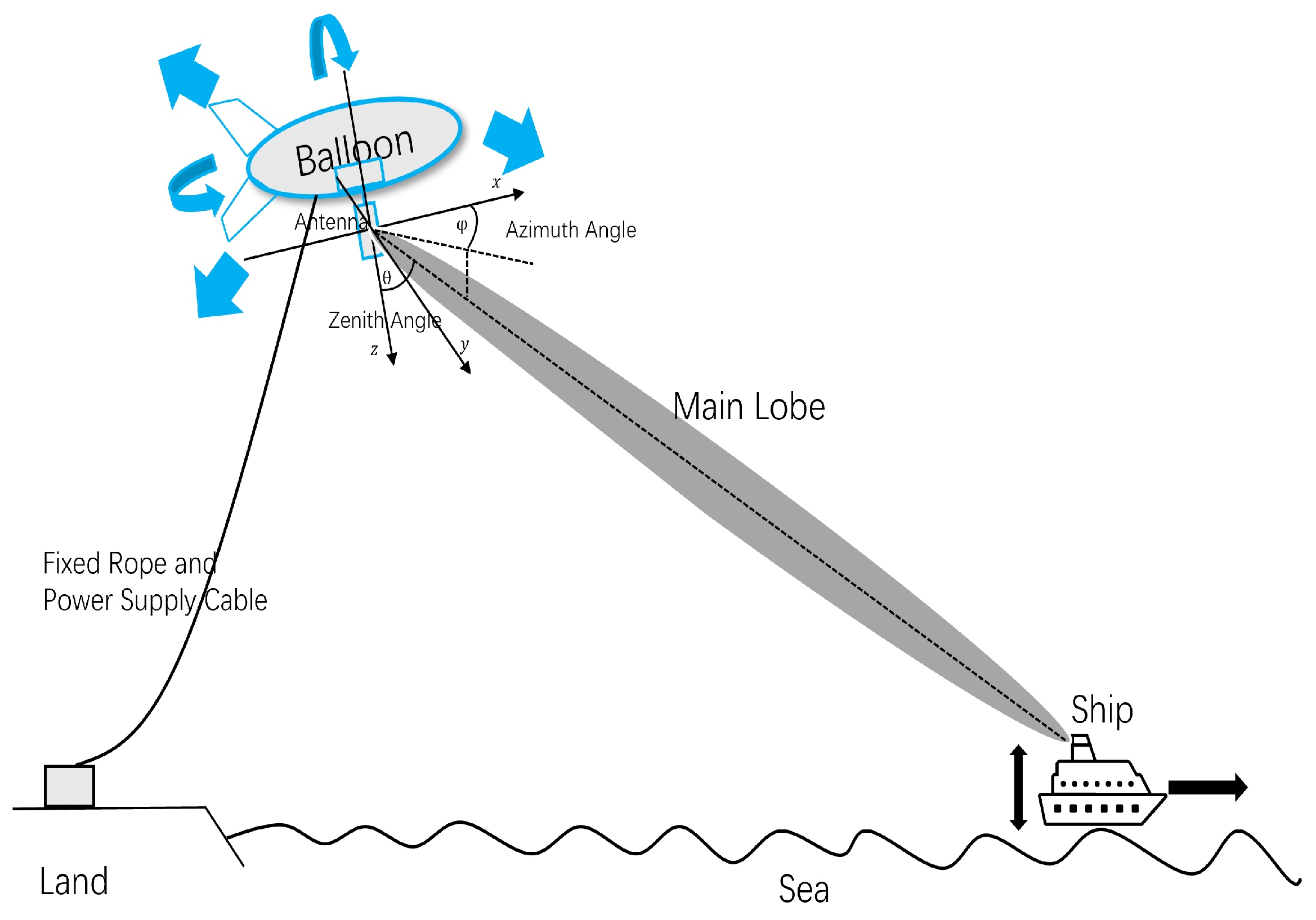
2.1. Network Model
2.2. Position Estimation
2.2.1. Transmitter Mobility Model
2.2.2. Receiver Mobility Model
2.2.3. Propagation Distance
2.3. Communication Model
2.3.1. Rician Fading Model and Path Loss
2.3.2. Channel Estimation Using MMSE
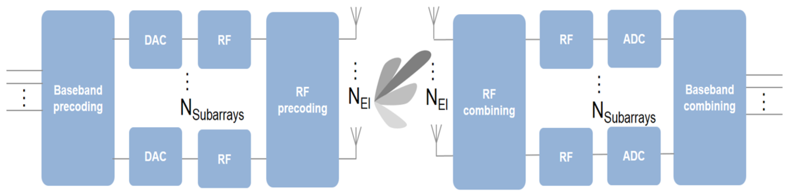
2.3.3. Beamforming Strategy Using MUSIC Algorithm
3. Conventional and Proposed Methods
3.1. Conventional Methods
3.1.1. Equal Power Allocation Method
3.1.2. CSI-Based Proportional Allocation Method
3.2. Proposed Method
3.2.1. CSI-Based Nonlinear Allocation Method
3.2.2. Adaptive Selection Method for
4. Simulation
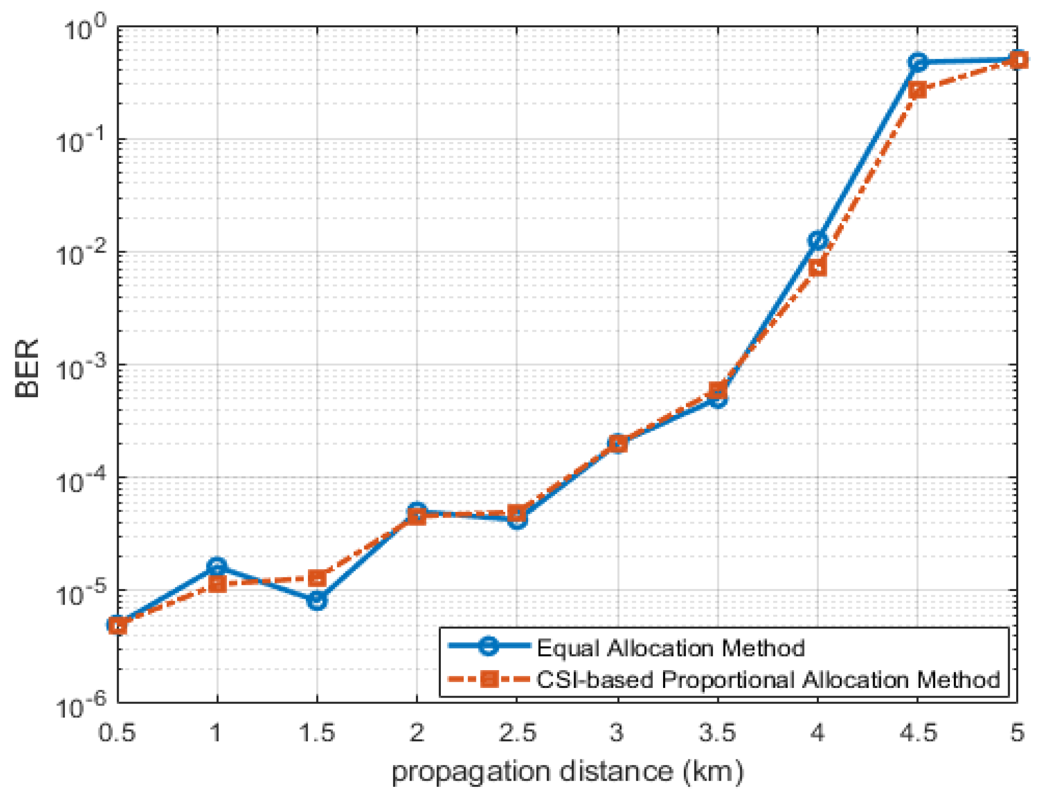
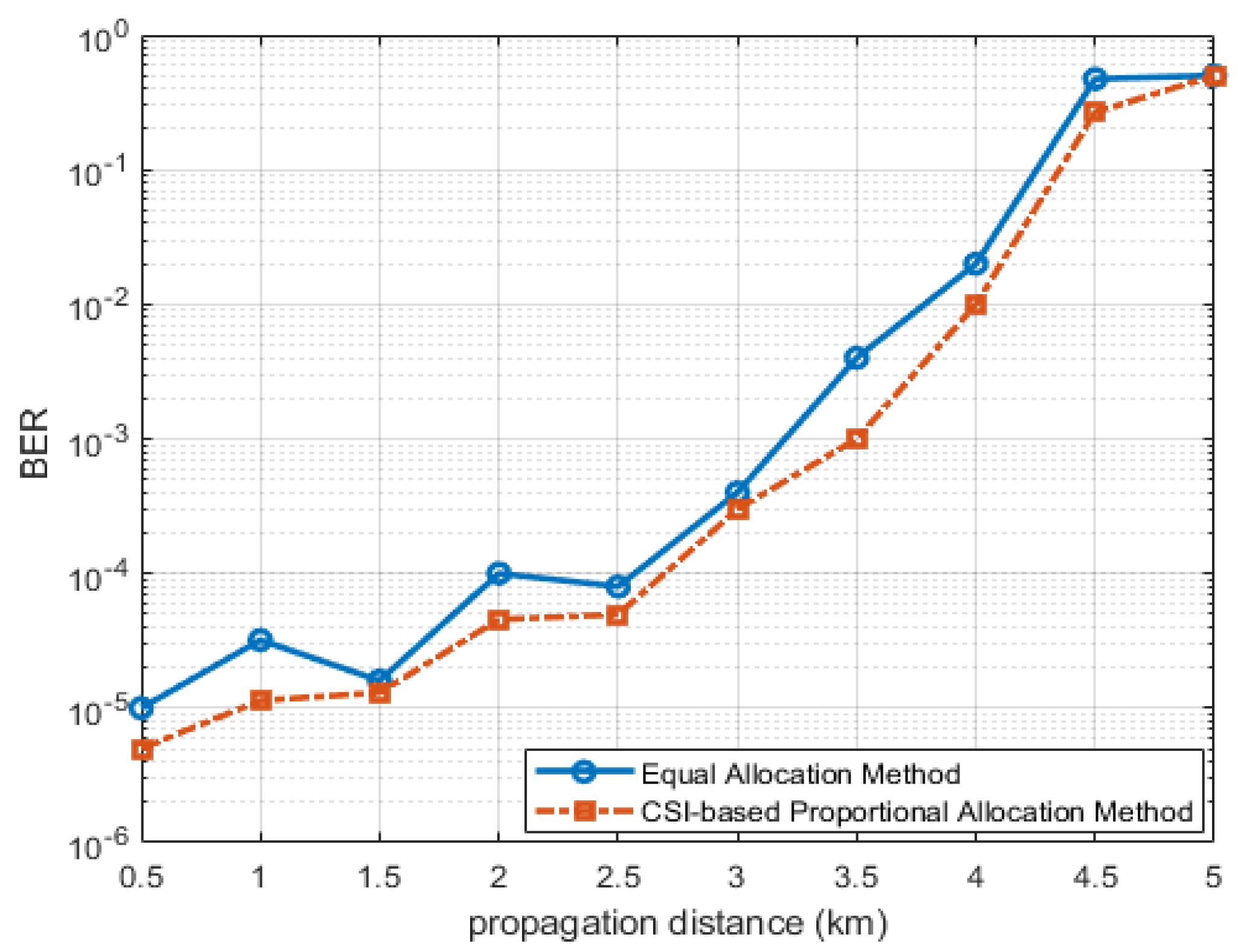
4.1. Comparison Between Conventional Methods
4.2. Proposed Method
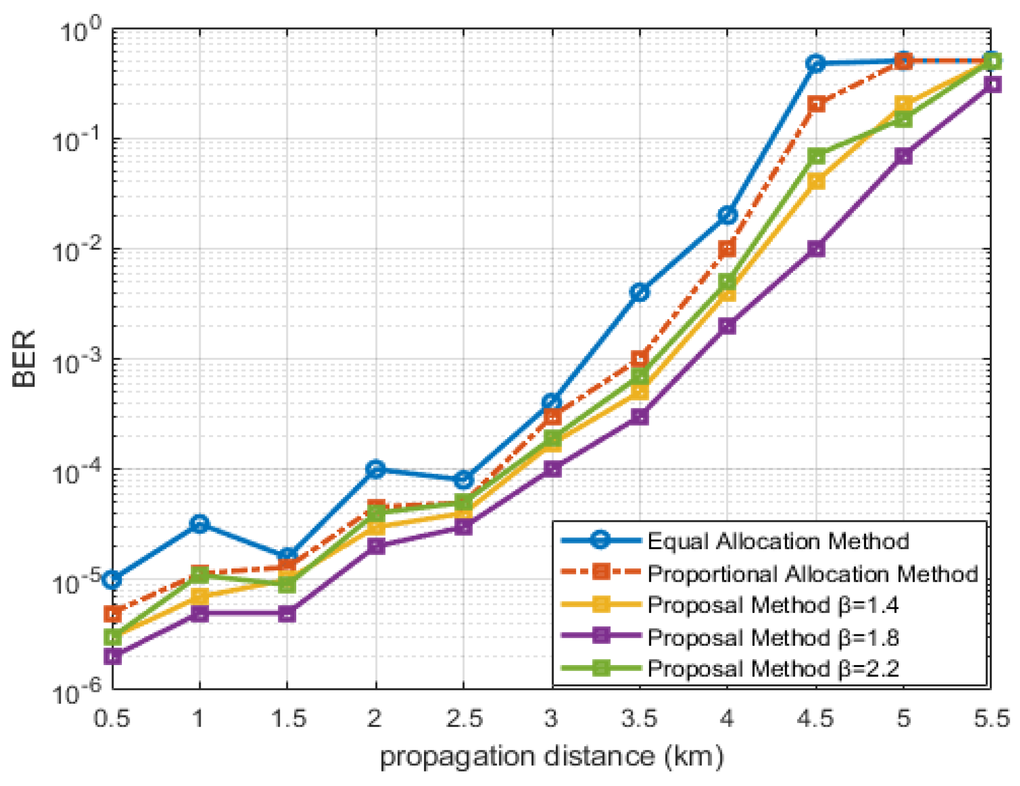
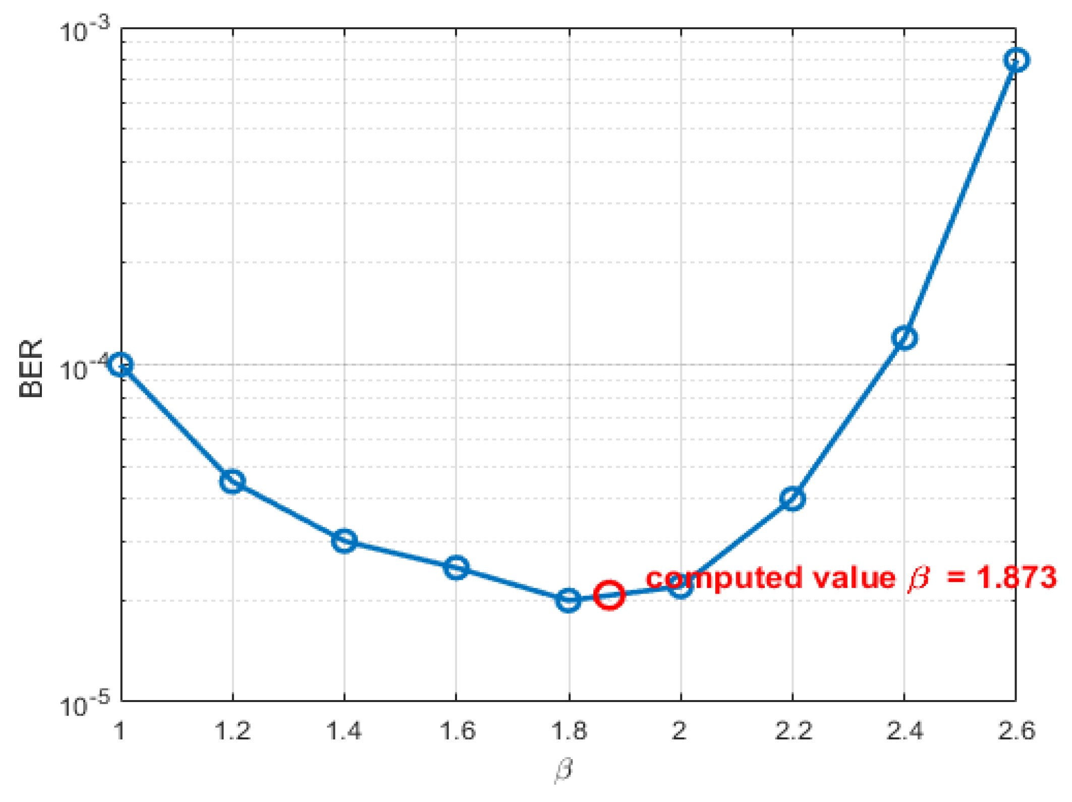
4.2.1. CSI-Based Nonlinear Allocation Method
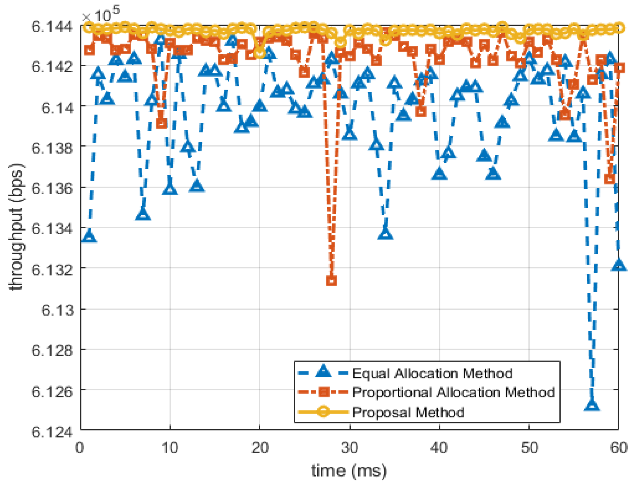
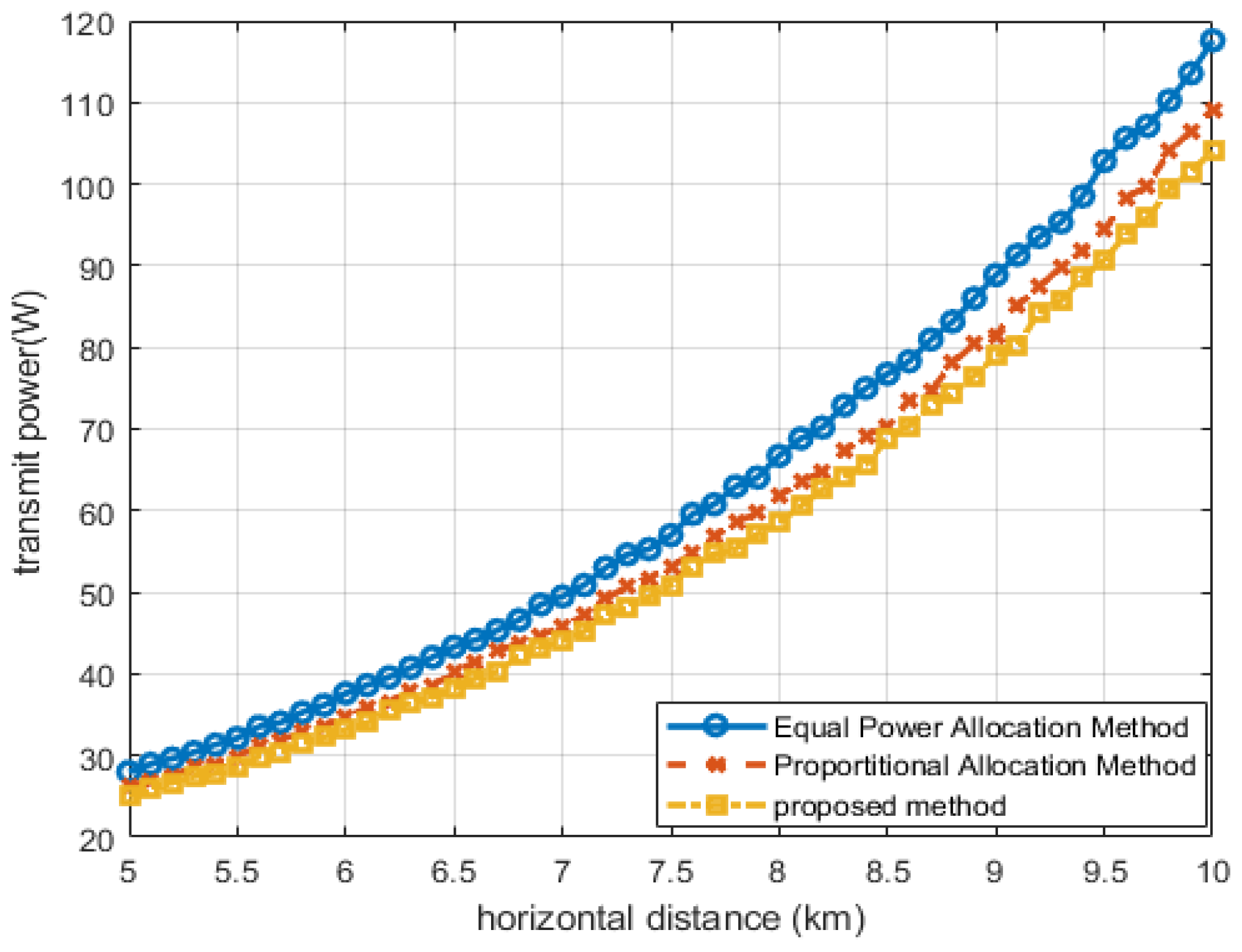
4.2.2. Dynamic Power Control Mechanism
5. Conclusions
Author Contributions
Funding
Data Availability Statement
Conflicts of Interest
References
- Jo, S.-W.; Shim, W.-S. LTE-Maritime: High-Speed Maritime Wireless Communication Based on LTE Technology. IEEE Access 2019, 7, 53172–53181. [Google Scholar]
- Rauniyar, S.; Orten, P.; Petersen, S.; Noll, J. WindNet: A Mobile Base Station Infrastructure For Maritime Industry. In Proceedings of the 2024 IEEE International Humanitarian Technologies Confer-ence (IHTC), Bari, Italy, 27–30 November 2024; pp. 1–6. [Google Scholar]
- Raulefs, R.; Bellido-Manganell, M.A.; Dammann, A.; Walter, M.; Wang, W. Propagation Channel for Communications and Navigation Between Moving Ships. In Proceedings of the OCEANS 2024, Halifax, NS, Canada, 23–26 September 2024; pp. 1–4. [Google Scholar]
- Ammar, S.; Amin, O.; Shihada, B. Tethered UAV-based Communications for Under-connected Near-shore Maritime Areas. In Proceedings of the 2024 IEEE International Black Sea Conference on Communications and Networking (BlackSeaCom), Tbilisi, Georgia, 24–27 June 2024; pp. 42–47. [Google Scholar]
- Yuxuan, G.; Yue, L.; Penghui, S. Research Status of Typical Satellite Communication Systems. In Proceedings of the 2021 19th International Conference on Optical Communications and Networks (ICOCN), Qufu, China, 23–27 August 2021; pp. 1–3. [Google Scholar]
- Kim, S.; Dietrich, C. Coexistence of Outdoor Wi-Fi and Radar at 3.5 GHz. IEEE Wirel. Commun. Lett. 2017, 6, 522–525. [Google Scholar]
- Yu, C.; Li, J.; Zhang, C.; Li, H.; He, R.; Lin, B. Maritime Broadband Communications: Ap-plications, Challenges and an Offshore 5G-virtual MIMO Paradigm. In Proceedings of the 2020 IEEE Intl Conf on Parallel & Distributed Processing with Applications, Big Data & Cloud Computing, Sustainable Computing & Communications, Social Computing & Networking (ISPA/BDCloud/SocialCom/SustainCom), Exeter, UK, 17–19 December 2020; pp. 1286–1291. [Google Scholar]
- Belmekki, B.E.Y.; Alouini, M.-S. Unleashing the Potential of Networked Tethered Flying Platforms: Prospects, Challenges, and Applications. IEEE Open J. Veh. Technol. 2022, 3, 278–320. [Google Scholar]
- Izet-Ünsalan, K.; Ünsalan, D. A low cost alternative for satellites- tethered ultra-high altitude balloons. In Proceedings of the 5th International Conference on Recent Advances in Space Technolo-gies—RAST2011, Istanbul, Turkey, 9–11 June 2011; pp. 13–16. [Google Scholar]
- Alsamhi, S.H.; Gupta, S.K.; Rajput, N.S. Performance evaluation of broadband service de-livery via tethered balloon technology. In Proceedings of the 2016 11th International Conference on Indus-trial and Information Systems (ICIIS), Roorkee, India, 3–4 December 2016; pp. 133–138. [Google Scholar]
- Dahman, G.; Couillard, D.; Grandmaison, M.-E.; Poitau, G.; Gagnon, F. Improved 2-Ray Model for Overwater Propagation Channels: Modeling the Instantaneous Variations in the Received Signal Strength. IEEE Wirel. Commun. Lett. 2019, 8, 865–868. [Google Scholar] [CrossRef]
- Cox, H.; Zeskind, R.; Owen, M. Robust adaptive beamforming. IEEE Trans. Acoust. Speech Signal Process. 1987, 35, 1365–1376. [Google Scholar] [CrossRef]
- Castro, M.A.C.; Cusicuna, J.L.A. Implementation of Water-Filling algorithm for optimal power allocation in the wireless channel of a MIMO 2 × 2 system over SDR. In Proceedings of the 2023 IEEE Colombian Caribbean Conference (C3), Barranquilla, Colombia, 22–25 November 2023; pp. 1–6. [Google Scholar]
- Ge, T.; Wang, Y.; Zhang, C.; Fang, Y. Reconfiguration in Maritime Networks Integrated with Dynamic High Altitude Balloons. In Proceedings of the ICC 2021—IEEE International Conference on Communications, Montreal, QC, Canada, 14–23 June 2021; pp. 1–6. [Google Scholar]
- Kubo, S.; Sakaguch, A.; Takimoto, T. Development of flying observation system with helium gas balloon and tilt rotors. In Proceedings of the 2014 14th International Conference on Control, Automation and Systems (ICCAS 2014), Gyeonggi-do, Republic of Korea, 22–25 October 2014; pp. 1627–1630. [Google Scholar]
- Kelif, J.-M. Coverage and performance of stratospheric balloons wireless networks. In Proceedings of the 2016 IEEE 27th Annual International Symposium on Personal, Indoor, and Mobile Radio Communications (PIMRC), Valencia, Spain, 4–8 September 2016; pp. 1–6. [Google Scholar]
- Cho, Y.S.; Kim, J.; Yang, W.Y.; Kang, C.G. MIMO Channel Models. In MIMO-OFDM Wireless Communications with MATLAB®; IEEE: Piscataway, NJ, USA, 2010; pp. 71–109. [Google Scholar]
- Guo, R.; Xing, H.; Wang, H. Medium And Long Term Load Forecasting Based On Improved Partial Least Square Method. In Proceedings of the 2020 International Conference on Smart Grids and En-ergy Systems (SGES), Perth, Australia, 23–26 November 2020; pp. 679–684. [Google Scholar]

| Parameter | Value |
|---|---|
| Transmission Power | 5 W |
| Number of Antenna Elements | 16 |
| Transmission Gain | −8 dB |
| Modulation Method | 16QAM |
| Carrier Frequency | 2.4 GHz |
| Number of Subcarriers | 48 |
| Doppler Frequency | 5 Hz |
| Number of Multipaths | 5 |
| Parameter | Value |
|---|---|
| Transmission Power | 5 W |
| Number of Antenna Elements | 16 |
| Transmission Gain | −8 dB |
| Modulation Method | 16QAM |
| Carrier Frequency | 2.4 GHz |
| Number of Subcarriers | 48 |
| Doppler Frequency | 5 Hz |
| Number of Multipaths | 5 |
| Time Step | 1 s |
| BER Threshold | |
| Power Adjustment Step | 0.5 W |
Disclaimer/Publisher’s Note: The statements, opinions and data contained in all publications are solely those of the individual author(s) and contributor(s) and not of MDPI and/or the editor(s). MDPI and/or the editor(s) disclaim responsibility for any injury to people or property resulting from any ideas, methods, instructions or products referred to in the content. |
© 2025 by the authors. Licensee MDPI, Basel, Switzerland. This article is an open access article distributed under the terms and conditions of the Creative Commons Attribution (CC BY) license (https://creativecommons.org/licenses/by/4.0/).
Share and Cite
Fang, T.; Wang, J.-h.; Cha, J.; Jeong, I.; Ahn, C.-J. A Study on Performance Improvement of Maritime Wireless Communication Using Dynamic Power Control with Tethered Balloons. Electronics 2025, 14, 1277. https://doi.org/10.3390/electronics14071277
Fang T, Wang J-h, Cha J, Jeong I, Ahn C-J. A Study on Performance Improvement of Maritime Wireless Communication Using Dynamic Power Control with Tethered Balloons. Electronics. 2025; 14(7):1277. https://doi.org/10.3390/electronics14071277
Chicago/Turabian StyleFang, Tao, Jun-han Wang, Jaesang Cha, Incheol Jeong, and Chang-Jun Ahn. 2025. "A Study on Performance Improvement of Maritime Wireless Communication Using Dynamic Power Control with Tethered Balloons" Electronics 14, no. 7: 1277. https://doi.org/10.3390/electronics14071277
APA StyleFang, T., Wang, J.-h., Cha, J., Jeong, I., & Ahn, C.-J. (2025). A Study on Performance Improvement of Maritime Wireless Communication Using Dynamic Power Control with Tethered Balloons. Electronics, 14(7), 1277. https://doi.org/10.3390/electronics14071277