

Through-Hole Buck Converters for Fast Prototyping: A Comparative Study

 ,
,  , , and
Abstract
1. Introduction
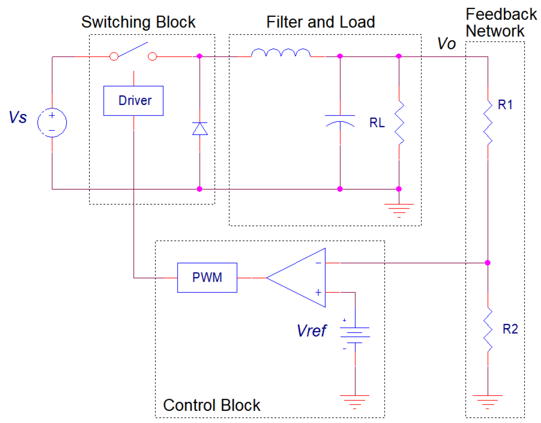
2. Material and Methods
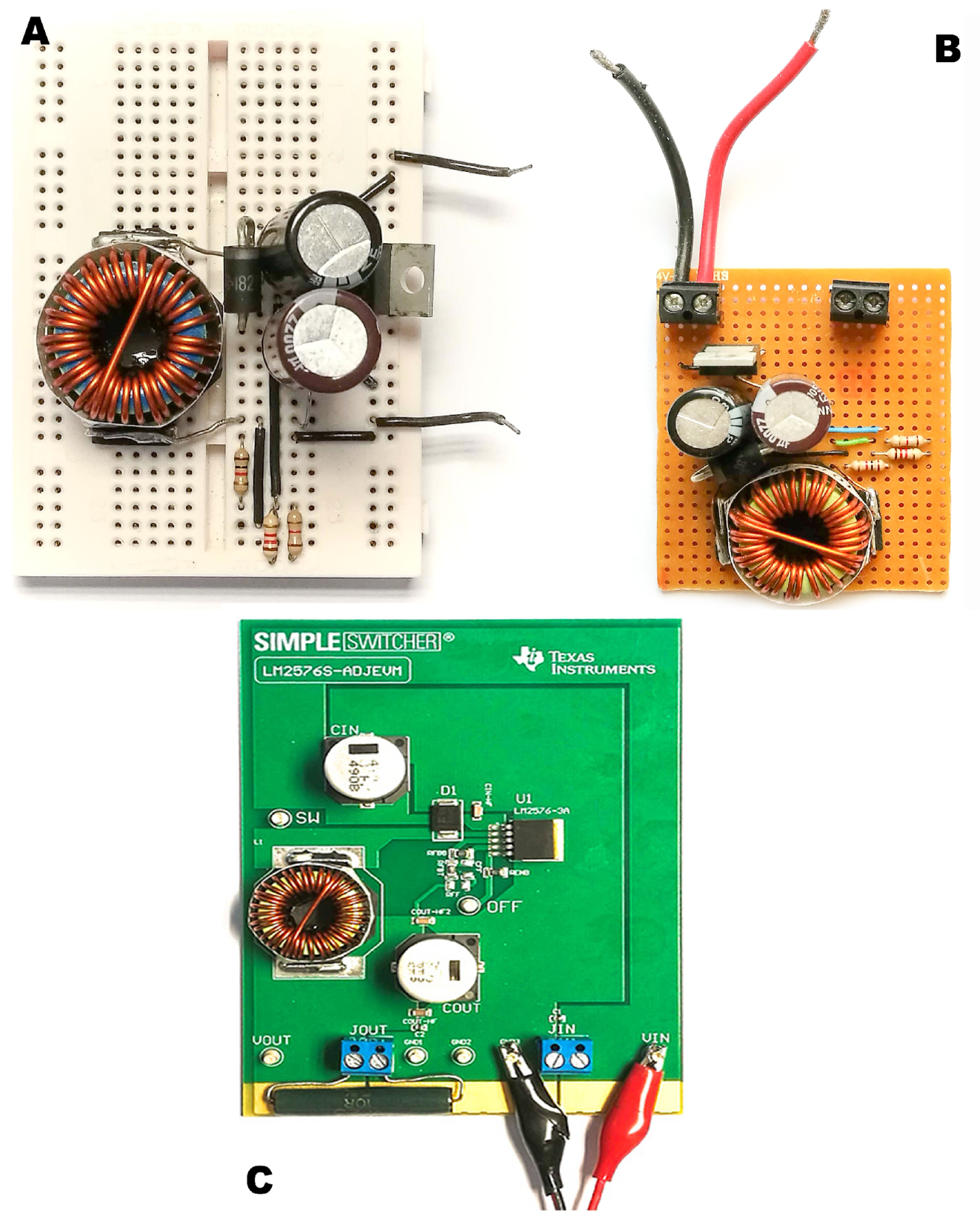
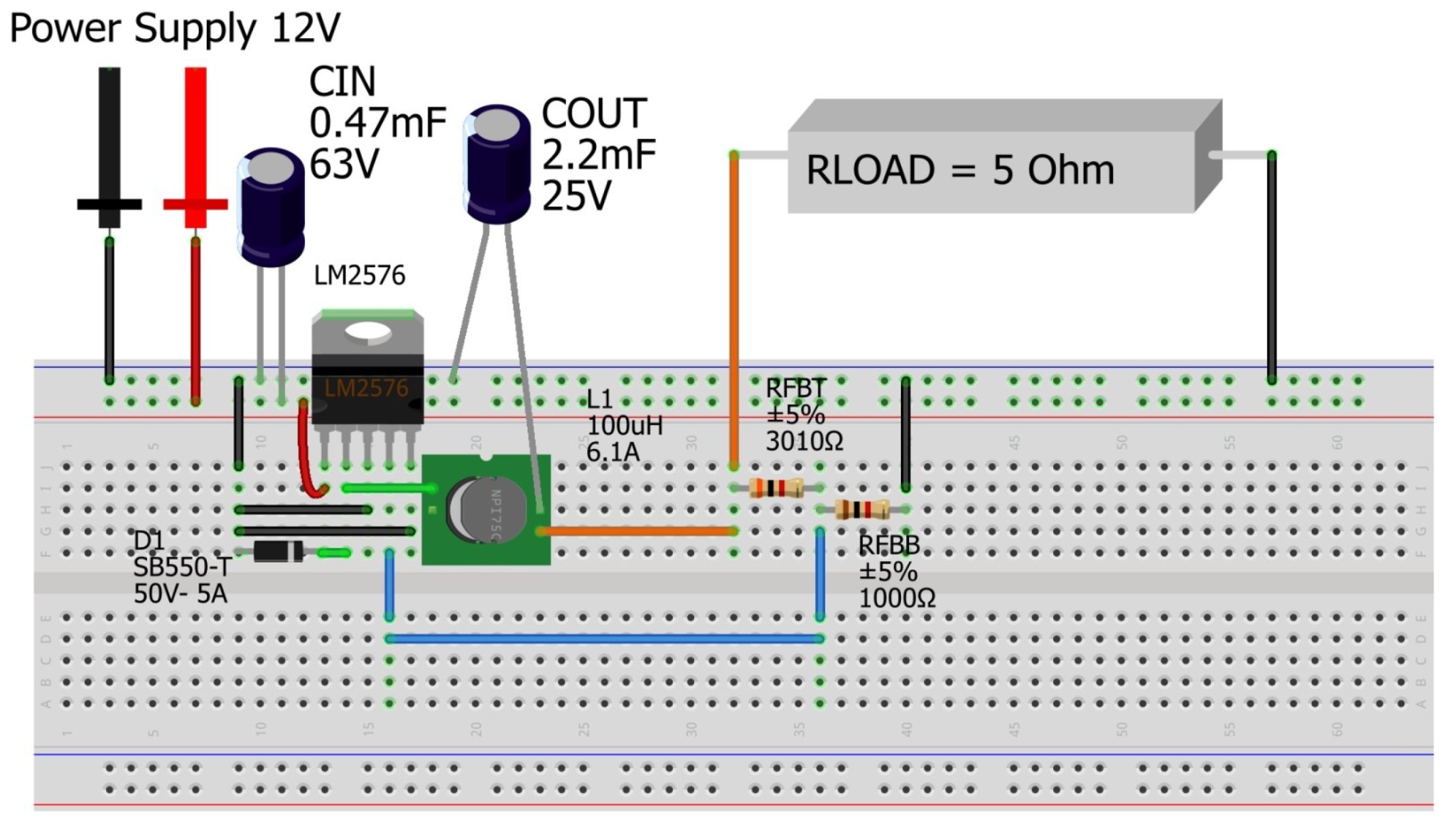
2.1. Design and Customization
2.2. Technical Issues to Overcome
2.2.1. Frequency and Current
2.2.2. Compactness
2.2.3. Layout Recommendations
2.2.4. Manufacturer Demonstration Board
2.3. Logistic and Economic Aspects to Consider
3. Results
3.1. Integrated Buck Switching Regulators on the Market: A Comparison
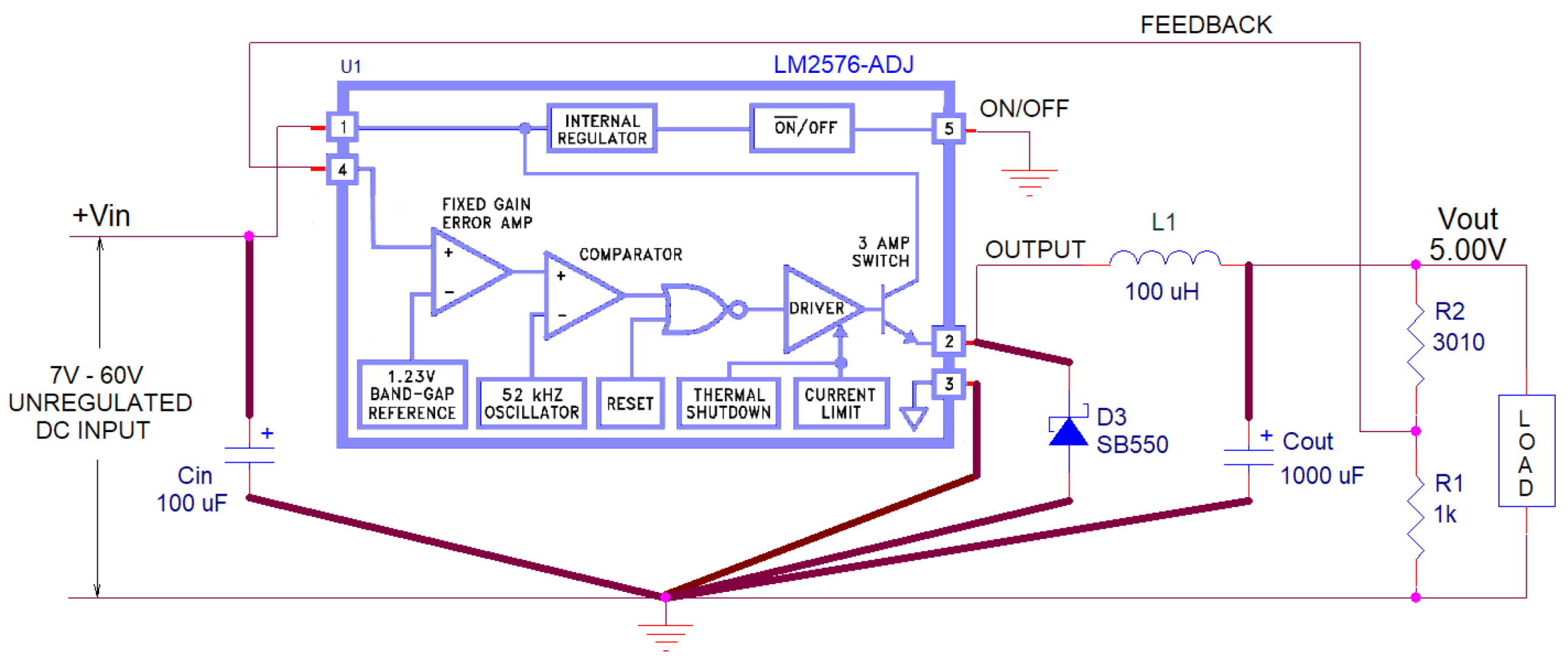
Candidate from the Comparison: LM2576-ADJ by Texas Instruments
- Its output current is remarkable (3 A), particularly when it comes in a manageable TO-220 package, which allows a heat sink to be easily installed.
- The wide input/output voltage range, as well as the possibility of using the fixed or adjustable version (7th column in Table 1), make this buck converter ideal from a practical point of view.
- Another distinguishing mark of the LM2576-ADJ is the ease with which it can be designed, simulated, or tested. The electronic component by Texas Instruments comes with an excellent datasheet with examples and tools to simplify the design process. The buck converter can be simulated online thanks to the WebenchTM tool, and its Spice model is also available in the list of components on the OrCADTM PSpiceTM 17.2 database. Moreover, the manufacturer offers a demonstration board, which is always helpful for designers.
- Its price and availability are also points in favor of the LM2576-ADJ. It is one of the cheapest switching regulators included in the study and is marketed by all the distributors that have been taken into account. Moreover, this buck converter is sold by two electronic firms, Texas Instruments and ON Semiconductor Corporation (Scottsdale, AZ, USA), which is also an advantage because its availability is more likely.
3.2. Experimental Comparison Focused on the LM2576-ADJ
3.3. Comparison of the Implementations
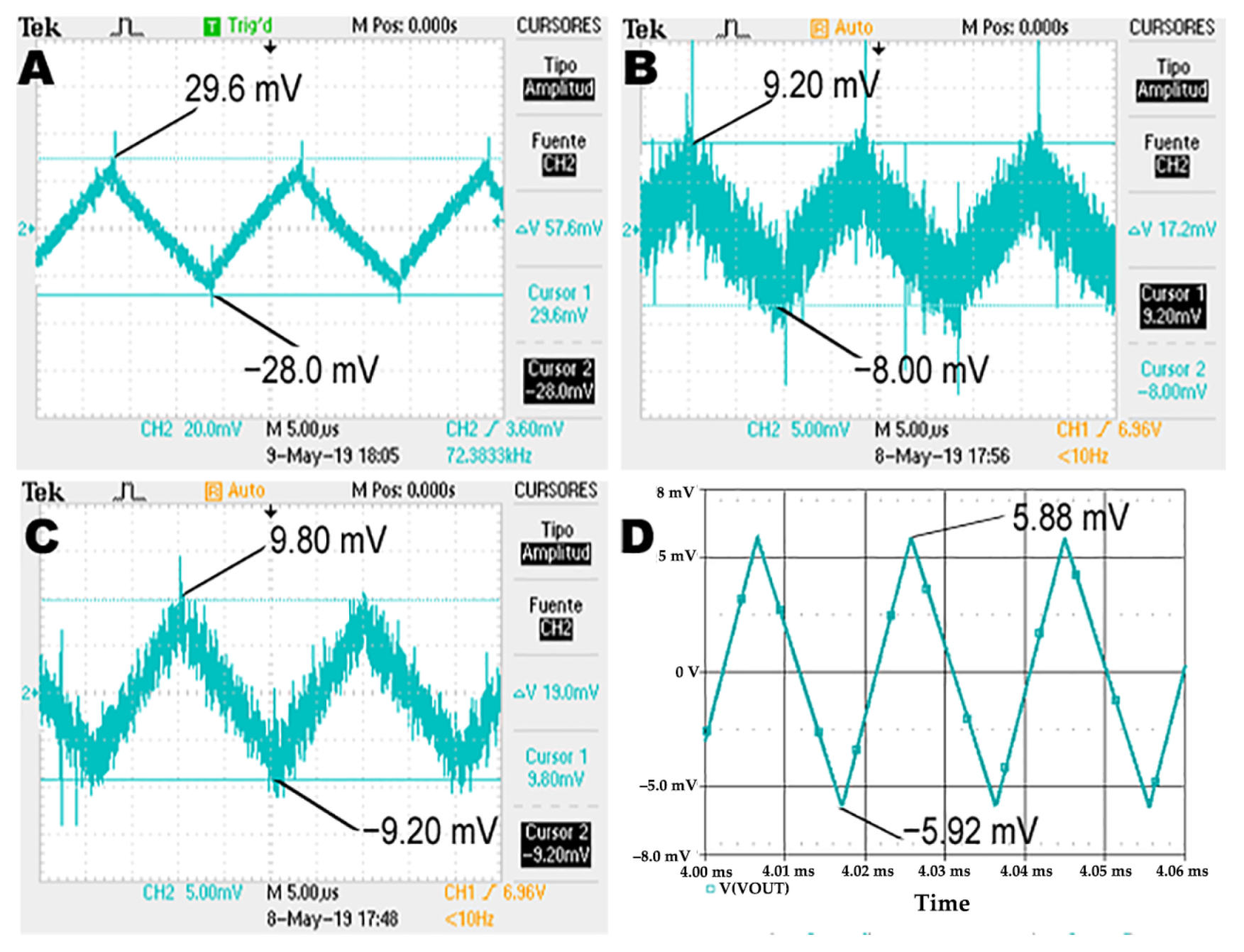
3.3.1. Output Voltage Ripple
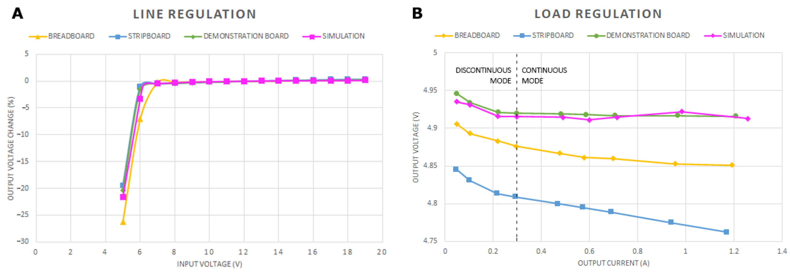
3.3.2. Line Regulation
3.3.3. Load Regulation
3.3.4. Coil Current Ripple
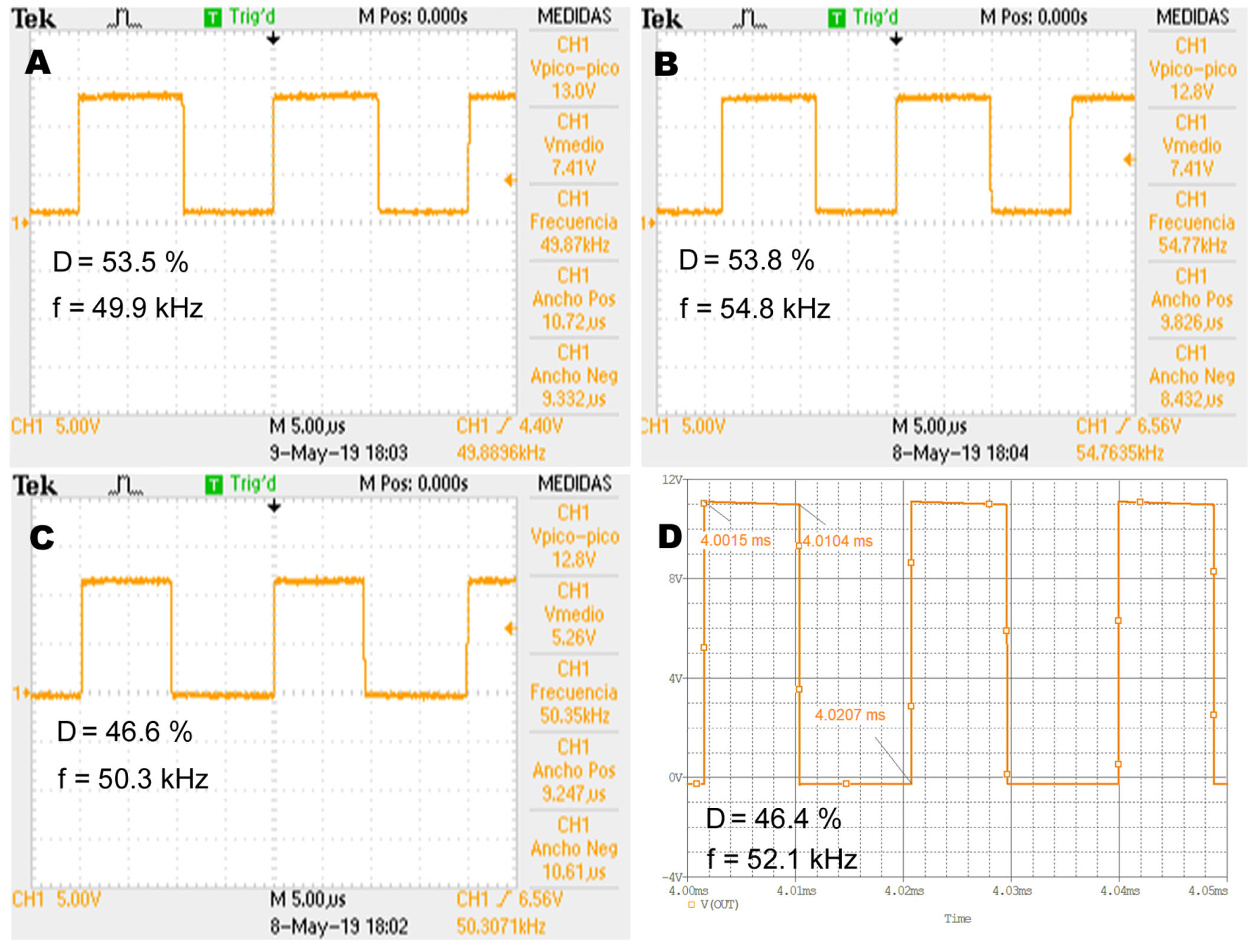
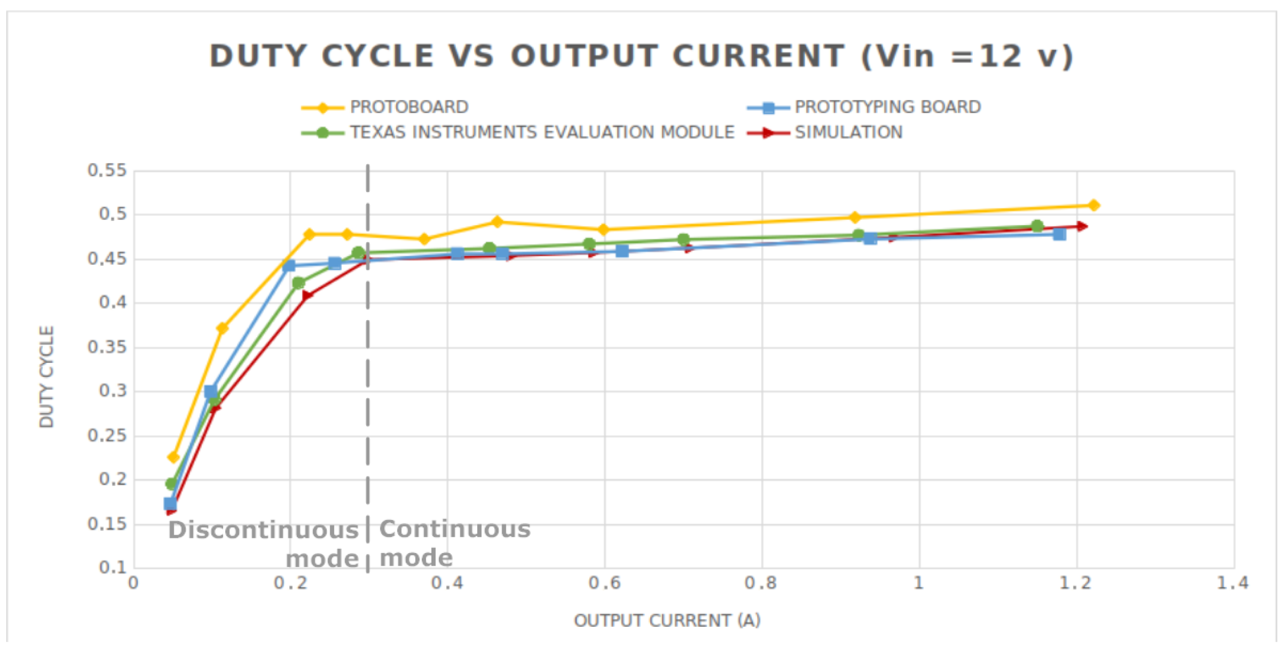
3.3.5. Duty Cycle Evolution Under Different Loads
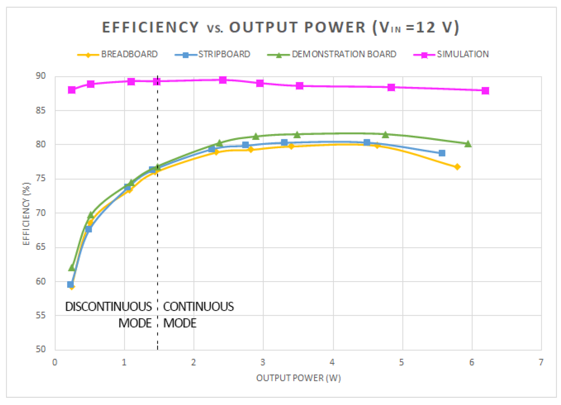
3.3.6. Efficiency
3.3.7. Conducted EMI Analysis
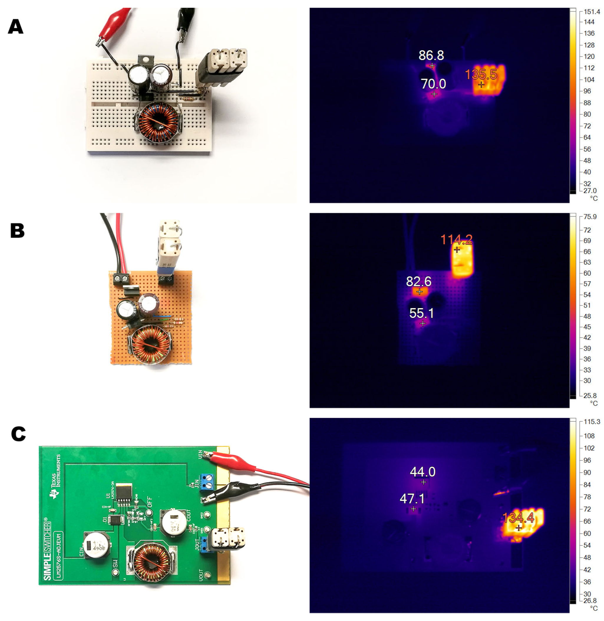
3.3.8. Thermal Study
- The values of (junction temperature thermal resistance) and (junction capsule thermal resistance) for TO-220 packages are 32.4 °C/W and 0.4 °C/W, respectively. In the case of SMT package (TO-263), and are 42.6 °C/W and 0.4 °C/W, respectively. It is important to clarify this point due to the discrepancies between thermal resistances provided by different manufacturers (Texas Instruments and Onsemi) for the same integrated circuit (LM2576-ADJ), since manufacturers follow different procedures to calculate these parameters [46].
- Due to the small thermal resistance between junction and capsule (0.4 °C/W ), the temperature of the junction () is going to be considered equal to the capsule (). Furthermore, the switching mode in which the buck converter works makes the value of even smaller due to the existence of a thermal impedance which depends on the switching frequency.
- The thermostated ambient temperature () in the laboratory was considered constant at 26 °C for the whole duration of the experiment.
4. Conclusions
Author Contributions
Funding
Data Availability Statement
Conflicts of Interest
References
- Savekar, A.; Wankhede, S.; Kumar, V. DC-DC Converter Market. Global Opportunity Analysis and Industry Forecast, 2020–2027. Allied Markey Research, Report Code: A05304, October 2020. Available online: https://www.alliedmarketresearch.com/press-release/dc-dc-converter-market.html (accessed on 1 February 2025).
- Luo, P.; Peng, D.; Wang, Y.; Zheng, X. Review of Solar Energy Harvesting for IoT Applications. In Proceedings of the 2018 IEEE Asia Pacific Conference on Circuits and Systems (APCCAS), Chengdu, China, 26–30 October 2018; pp. 512–515. [Google Scholar] [CrossRef]
- Dileep, G.; Singh, S.N. Selection of non-isolated DC-DC converters for solar photovoltaic system. Renew. Sustain. Energy Rev. 2017, 76, 1230–1247. [Google Scholar] [CrossRef]
- Swaminathan, N.; Cao, Y. An Overview of High-Conversion High-Voltage DC-DC Converters for Electrified Aviation Power Distribution System. IEEE Trans. Transp. Electrif. 2020, 6, 1740–1754. [Google Scholar] [CrossRef]
- Martínez-Heredia, J.M.; Colodro, F.; Mora-Jiménez, J.L.; Remujo, A.; Soriano, J.; Esteban, S. Development of GaN Technology-Based DC/DC Converter for Hybrid UAV. IEEE Access 2020, 8, 88014–88025. [Google Scholar] [CrossRef]
- Chakraborty, S.; Vu, H.-N.; Hasa, M.M.; Tran, D.-D.; Baghdadi, M.E.; Hegazy, O. DC-DC Converter Topologies for Electric Vehicles, Plug-in Hybrid Electric Vehicles and Fast Charging Stations: State of the Art and Future Trends. Energies 2019, 12, 1569. [Google Scholar] [CrossRef]
- Jørgensen, K.L.; Zhang, Z.; Andersen, M.A.E. Next generation of power electronic-converter application for energy-conversion and storage units and systems. Clean Energy 2019, 3, 307–315. [Google Scholar] [CrossRef]
- Xiao, J.; Peterchev, A.V.; Zhang, J.; Sanders, S.R. A 4-/spl mu/a quiescent-current dual-mode digitally controlled buck converter IC for cellular phone applications. IEEE J. Solid-State Circuits 2004, 39, 2342–2348. [Google Scholar] [CrossRef]
- Chen, G.; Hanson, S.; Blaauw, D.; Sylvester, D. Circuit Design Advances for Wireless Sensing Applications. Proc. IEEE 2010, 98, 1808–1827. [Google Scholar] [CrossRef]
- Baharudin, N.H.; Mansur, T.M.N.T.; Hamid, F.A.; Misrun, M.I. Performance Analysis of DC-DC Buck converter for renewable energy application. In Proceedings of the 1st International Conference on Green and Sustainable Computing (IGoGeS), Pittsburgh, PA, USA, 24–25 October 2017; Available online: https://iopscience.iop.org/article/10.1088/1742-6596/1019/1/012020/pdf (accessed on 1 February 2025).
- Mostafa, T.M.; Muharam, A.; Hattori, R. Wireless battery charging system for drones via capacitive power transfer. In Proceedings of the 2017 IEEE PELS Workshop on Emerging Technologies: Wireless Power Transfer (WoW), Chongqing, China, 20–22 May 2017; pp. 1–6. [Google Scholar] [CrossRef]
- Mathúna, C.Ó.; Wang, N.; Kulkarni, S.; Roy, S. Review of Integrated Magnetics for Power Supply on Chip (PwrSoC). IEEE Trans. Power Electron. 2012, 27, 4799–4816. [Google Scholar] [CrossRef]
- Coleman, W.E.; Jean, D.; Bradbury-Bennett, J.R. Stencil design for mixed technology through-hole/SMT placement and reflow. Solder. Surf. Mt. Technol. 2000, 12, 8–12. [Google Scholar] [CrossRef]
- He, J.; Cen, Y.; Alelaumi, S.; Won, D. An Artificial Intelligence-Based Pick-and-Place Process Control for Quality Enhancement in Surface Mount Technology. IEEE Trans. Compon. Packag. Manuf. Technol. 2022, 12, 1702–1711. [Google Scholar] [CrossRef]
- Nguty, T.A.; Philpott, J.D.; Ekere, N.N.; Teckle, S.; Salam, B.; Rajkumar, D. Rework techniques process evaluation for chip scale packages. IEEE Trans. Electron. Packag. Manuf. 2000, 23, 200–207. [Google Scholar] [CrossRef]
- He, W. Analysis on the Component Movement in Electronic Assembly. In Proceedings of the 2021 8th International Forum on Electrical Engineering and Automation (IFEEA), Xi’an, China, 3–5 September 2021; pp. 116–119. [Google Scholar] [CrossRef]
- Houari, B.; Aissa, B.; Lakhdar, L.; Yazid, B.E. DC/DC buck Converter Prototype for Educational Nanosatellite Power Sub-System. In Proceedings of the 2023 International Conference on Advances in Electronics, Control and Communication Systems (ICAECCS), Blida, Algeria, 6–7 March 2023; pp. 1–6. [Google Scholar] [CrossRef]
- Rai, J.N.; Gupta, N.; Bansal, P. Design and analysis of DC-DC boost converter. Int. J. Adv. Res. Innov. 2016, 4, 499–502. [Google Scholar] [CrossRef]
- Eguchi, K.; Rubpongse, R.; Shibata, A.; Ishibashi, T. Synthesis and analysis of a cross-connected Fibonacci dc/dc converter with high voltage gain. Energy Rep. 2020, 6, 130–136. [Google Scholar] [CrossRef]
- Collins, N.; Lonergan, S. Solder Up! From Breadboard to Circuit Board. In Handmade Electronic Music; Routledge: London, UK, 2020. [Google Scholar]
- Hamblen, J.O.; van Bekkum, G.M.E. An Embedded Systems Laboratory to Support Rapid Prototyping of Robotics and the Internet of Things. IEEE Trans. Educ. 2013, 56, 121–128. [Google Scholar] [CrossRef]
- Wang, C.; Yeh, H.-M.; Wang, B.; Wu, T.-Y.; Tsai, H.-R.; Liang, R.-H.; Hung, Y.-P.; Chen, M.Y. CircuitStack: Supporting Rapid Prototyping and Evolution of Electronic Circuits. In Proceedings of the 29th Annual Symposium on User Interface Software and Technology (UIST ’16), Tokyo, Japan, 16–19 October 2016; pp. 687–695. [Google Scholar] [CrossRef]
- Ferreiro, A.L.; Simón, A.R.A.; Casas, S.L.; Meléndez, A.A.N. A current-controlled DC-to-DC switch mode power converters emulator software. In Proceedings of the 2016 Technologies Applied to Electronics Teaching, TAEE, Seville, Spain, 22–24 June 2016. [Google Scholar] [CrossRef]
- Zaitsu, R. Voltage Mode Boost Converter Small Signal Control Loop Analysis Using the TPS61030; Application Report; Texas Instruments: Dallas, TX, USA, 2007; pp. 1–21. [Google Scholar]
- Crowel, G. How Much Power and How High of a Frequency Can a Breadboard Handle? From Circuit Bread.com. Available online: https://www.circuitbread.com/ee-faq/how-much-power-and-how-high-of-a-frequency-can-a-breadboard-handle (accessed on 10 April 2022).
- Wikipedia. The Free Encyclopedia. Breadboard. Available online: https://en.wikipedia.org/wiki/Breadboard (accessed on 1 February 2025).
- Musunuri, S.; Chapman, P.L.; Zou, J.; Liu, C. Inductor design for monolithic DC-DC converters. In Proceedings of the IEEE 34th Annual Conference on Power Electronics Specialist, 2003, PESC ’03, Acapulco, Mexico, 15–19 June 2003; Volume 1, pp. 227–232. [Google Scholar] [CrossRef]
- Crane, L. Selecting the Best Inductor for a DC-DC Converter. Craftcoil, Application Notes, Document 469-1, July 2017. Available online: https://www.coilcraft.com/getmedia/d4009ece-69be-49a6-9185-9cbacb65e3aa/Doc469_selecting_inductors.pdf (accessed on 1 February 2025).
- IPC-2221C—Association Connecting Electronics Industries. Generic Standard on Printed Board Design. 2024. Available online: https://shop.ipc.org/ipc-2221/ipc-2221-standard-only/Revision-c/english (accessed on 1 February 2025).
- Zhang, H.J. PCB Layout Considerations for Non-Isolated Switching Power Supplies, Analog Application Note 136 (AN136-1), June 2012. pp. 1–14. Available online: https://www.analog.com/en/resources/app-notes/an-136.html (accessed on 1 February 2025).
- Kollman, R. Constructing Your Power Supply: Layout Considerations; Texas Instruments Application Note SLUP230; Texas Instruments Inc.: Dallas, TX, USA, 2005. [Google Scholar]
- Kulkarni, S.; Bangade, S.; Khadse, M.; Waghulde, D.; Aher, P.; Gaikwad, K.; Thakurdesai, S. Design and optimization of the on board DC/DC converters of Swayam satellite. In Proceedings of the 2014 IEEE International Conference on Power Electronics, Drives and Energy Systems (PEDES), Mumbai, India, 16–19 December 2014; pp. 1–6. [Google Scholar] [CrossRef]
- Glaser, C. Five steps to a great PCB layout for a step-down converter. In Analog Applications Journal; Texas Instruments Inc.: Dallas, TX, USA, 2015; Available online: https://www.ti.com/lit/an/slyt614/slyt614.pdf?ts=1742720268015 (accessed on 1 February 2025).
- Bhargava, A.; Pommerenke, D.; Kam, K.W.; Centola, F.; Lam, C.W. DC-DC Buck Converter EMI Reduction Using PCB Layout Modification. IEEE Trans. Electromagn. Compat. 2011, 53, 806–813. [Google Scholar] [CrossRef]
- Ott, H. Electromagnetic Compatibility Engineering; John Wiley and Sons: New York, NY, USA, 2009. [Google Scholar]
- Ott, H. Noise Reduction Techniques in Electronic Systems, 2nd ed.; John Wiley and Sons: Chichester, UK, 1988. [Google Scholar]
- Simpson, C. Linear and Switching Voltage Regulator Fundamental Part 1. Texas Instruments. Available online: https://www.ti.com/lit/an/snva559/snva559.pdf (accessed on 1 February 2025).
- Tucker, J. Understanding output voltage limitations of DC/DC buck converters. In Analog Applications Journal; Texas Instruments Inc.: Dallas, TX, USA, 2008; Available online: https://www.ti.com/lit/an/slyt293/slyt293.pdf?ts=1742730170338&ref_url=https%253A%252F%252Fwww.google.com%252F (accessed on 1 February 2025)High-Performance Analog Products.
- Texas Instruments, LM2576S-ADJEVM User’s Guide. User’s Guide SNVU527, June 2016. Available online: https://www.ti.com/lit/pdf/snvu527 (accessed on 1 February 2025).
- Chew, L.W. The effect of higher order model decoupling capacitors in the design of a power delivery network. In Proceedings of the 2012 4th Asia Symposium on Quality Electronic Design (ASQED), Penang, Malaysia, 10–11 July 2012; pp. 117–122. [Google Scholar] [CrossRef]
- Erickson, R.W.; Maksimović, D. Fundamentals of Power Electronics; Springer: Berlin/Heidelberg, Germany, 2020. [Google Scholar]
- Himmelstoss, F.A.; Edelmoser, K.H. Concept to reduce the ringing during the discontinuous mode of a DC/DC converter. In Proceedings of the 2017 19th International Conference on Electrical Drives and Power Electronics (EDPE), Dubrovnik, Croatia, 4–6 October 2017; pp. 106–111. [Google Scholar] [CrossRef]
- Hart, D.W. Power Electronics; McGraw-Hill Companies Inc.: New York, NY, USA, 2010. [Google Scholar]
- Texas Instruments. Understanding Buck Power Stages in Switchmode Power Supplies. Application Report SLVA057, March 1999. Available online: https://www.ti.com/lit/an/slva057/slva057.pdf (accessed on 1 February 2025).
- Mohan, G.M.; Mukesh, P.; Yogesh, H. Effect of Non-Idealities on the Design and Performance of a DC-DC Buck Converter. J. Power Electron. 2016, 16, 832–839. [Google Scholar] [CrossRef]
- Edwards, D.; Nguyen, H. Semiconductor and IC Package Thermal Metrics; Texas Instruments Application Note SPRA953D; Texas Instruments Inc.: Dallas, TX, USA, 2003. [Google Scholar]
- Lall, B.S.; Guenin, B.M.; Molnar, R.J. Methodology for thermal evaluation of multichip modules. In Proceedings of the 1995 IEEE/CPMT 11th Semiconductor Thermal Measurement and Management Symposium (SEMI-THERM), San Jose, CA, USA, 7–9 February 1995; pp. 72–79. [Google Scholar] [CrossRef]


| Manufacturer | Model | Input | Output | Package | Limited | Price/ | Simulation | |||||
|---|---|---|---|---|---|---|---|---|---|---|---|---|
| Voltage | Voltage | Maximun | Output | Maximun | Evaluation | Number | Units | Tools | Supplier | |||
| (Min/ | (Min/ | Output | Type | Switching | Module | of External | (*) | Availability | Availability | |||
| Max) | Max) | Current | Frequency | Availability | Components | (**) | (***) | |||||
| Linear Technology (now Analog Devices) | LT1074 | 8/45 V | 8/35 V | 5 A | TO-220 | Adjustable | 110 kHz | No | Yes | 15.86 €/1 (‡) | iii | 2, 3, 4 |
| LT1074HV | 8/64 V | 8/45 V | 5 A | TO-220 | Adjustable | 125 kHz | No | Yes | 18.76 €/1 (‡) | iii | 2, 3, 4 | |
| LT1076 | 8/45 V | 8/35 V | 2 A | TO-220 | Adjustable | 110 kHz | No | Yes | 10.35 €/1 (‡) | iii | 2, 3, 4 | |
| LT1076HV | 8/64 V | 8/45 V | 2 A | TO-220 | Adjustable | 125 kHz | No | Yes | 16,12 €/1 (‡) | iii | 2, 3, 4 | |
| Maxim (now Analog Devices) | MAX638AMJA/883B | 2.2/16.5 V | 1.25/16 V | 525 mA | DIP-8 | Adjustable | 65 kHz | No | Yes (†) | 25.00 €/1 | - | 4 |
| MAX5035BUPA | 7.5/76 V | 1.25/13.2 V | 1 A | DIP-8 | Fixed/Adjustable | 125 kHz | Yes | Yes | 3.80 €/1 | ii | 4 | |
| MAX758ACPA+ | 4/16 V | 1.25/16 V | 750 mA | DIP-8 | Fixed/Adjustable | 190 kHz | No | Yes | 10.62 €/1 (‡) | - | 3, 4 | |
| ON Semiconductor | LM2574 | 4/40 V | 1.23/37 V | 500 mA | DIP-8 | Fixed | 52 kHz | No | Yes | 1.74 €/1 | i | 1, 2, 3, 4 |
| LM2576/LM2576-ADJ | 4/40 V | 1.23/37 V | 3 A | TO-220 | Fixed/Adjustable | 52 kHz | No | Yes | 2.56 €/5 | i | 1, 2, 3, 4 | |
| LM2575/LM2575-ADJ | 4/40 V | 1.23/37 V | 1 A | TO-220 | Fixed/Adjustable | 52 kHz | No | Yes | 2.29 €/1 | i | 1, 2, 3, 4 | |
| ST Microelectronics | L296/L296P | 9/46 V | 5.1/40 V | 4 A | Multiwatt 15 L | Fixed/Adjustable | 200 kHz | No | No ()() | 13.58 €/1 | ii | 1, 2, 3, 4 |
| L4970A | 15/50 V | 5.1/40 V | 10 A | Multiwatt 15 L | Fixed | 200 kHz | No | No () | 15.23 €/1 | ii | 1, 2, 3, 4 | |
| L4975A | 15/50 V | 5.1/40 V | 5 A | Multiwatt 15 L | Fixed | 200 kHz | No | No () | 17.86 €/1 | ii | 1, 2 | |
| Texas Instruments | LM2574 | 4/40 V | 1.23/37 V | 500 mA | DIP-8 | Fixed/Adjustable | 52 kHz | No | Yes | 3.59 €/1 | i, iii | 1, 2, 3, 4 |
| LM2574HV | 4/60 V | 1.23/37 V | 500 mA | DIP-8 | Fixed/Adjustable | 52 kHz | No | Yes | 4.46 €/1 | ii, iii | 1, 3, 4 | |
| LM2576 | 4/40 V | 3.33/37 V | 3 A | TO-220 | Fixed/Adjustable | 52 kHz | Yes | Yes | 3.40 €/5 | i, iii | 1, 2, 3, 4 | |
| LM2576HV | 4/60 V | 3.33/37 V | 3 A | TO-220 | Fixed/Adjustable | 52 kHz | No | Yes | 9.55 €/1 | ii, iii | 1, 2, 3, 4 | |
| LM2575 | 4/40 V | 3.33/37 V | 1 A | TO-220 | Fixed/Adjustable | 100 kHz | Yes | Yes | 3.58 €/1 | i, iii | 1, 2, 3, 4 | |
| LM2575HV | 4/40 V | 3.33/57 V | 1 A | TO-220 | Fixed/Adjustable | 100 kHz | No | Yes | 5.73 €/1 | ii, iii | 1, 2, 3, 4 | |
| LM2595 | 4.75/40 V | 1.2/37 V | 1 A | TO-220 | Fixed/Adjustable | 150 kHz | No | Yes | 4.38 €/1 | ii, iii | 3, 4 | |
| LM2596 | 4.75/40 V | 1.2/37 V | 3 A | TO-220 | Fixed/Adjustable | 150 kHz | Yes | Yes | 5.52 €/1 | ii, iii | 1, 2, 3, 4 |
| Device | Description | Manufacturer | Part Number |
|---|---|---|---|
| D | Diode, Schottky, 50 V, 5 A, | On semiconductor | SB550 |
| L | Inductor, Toroid, 100 µH, 6.1 A, 0.035 | Bourns (Riverside, CA, USA) | PM2120-101K-RC |
| CAP, AL, 470 µF, 63 V, ±20%, 0.053 | Panasonic (Kadoma, Japan) | EEUFC1J471 | |
| CAP, AL, 2200 µF, 63 V, ±20%, 0.028 | Panasonic | EEUFC1E222S | |
| R1 | 1 k resistor, 5%, 0.25 W | RS PRO (London, UK) | 707-7666 |
| R2 | 1.2 k and 1.8 k resistors in series, 5%, 0.25 W | RS PRO | 707-7678, 739-7471 |
| Voltage Ripple | Line Regulation | Load Regulation | Switching Frequency | Duty Cycle | Maximum Efficiency | THD | LM2576-ADJ Temperature | |
|---|---|---|---|---|---|---|---|---|
| Breadboard | 57.6 | 0.37 % | 0.33% | 49.9 kHz | 53.5% | 79.9% | 1.02% | 86.8 °C |
| Stripboard | 17.2 | 0.32 % | 0.79% | 54.8 kHz | 53.8% | 80.3% | 1.12% | 82.6 °C |
| Demonstration board | 19.0 | 0.30% | 0.06% | 50.3 kHz | 46.6% | 81.6% | 0.45% | 44.0 °C |
| Simulation | 11.8 | 0.28 % | 0.04% | 52.1 kHz | 46.4% | 89.5% | – | – |
| Theoretical Temperature TO220 Package | Theoretical Temperature SMT Package | Breadboard | Stripboard | Demonstration Board | |
|---|---|---|---|---|---|
| LM2576-ADJ | 44.2 °C | 49.9 °C | 86.8 °C | 82.6 °C | 44.0 °C |
| Freewheeling diode | 30.4 °C | 56.5 °C | 70.0 °C | 55.1 °C | 47.1 °C |
Disclaimer/Publisher’s Note: The statements, opinions and data contained in all publications are solely those of the individual author(s) and contributor(s) and not of MDPI and/or the editor(s). MDPI and/or the editor(s) disclaim responsibility for any injury to people or property resulting from any ideas, methods, instructions or products referred to in the content. |
© 2025 by the authors. Licensee MDPI, Basel, Switzerland. This article is an open access article distributed under the terms and conditions of the Creative Commons Attribution (CC BY) license (https://creativecommons.org/licenses/by/4.0/).
Share and Cite
Muñoz, J.V.; Nieto-Nieto, L.M.; Pulido-Lopez, L.; Aguilar-Peña, J.D.; Gonzalez-Rodriguez, A.G. Through-Hole Buck Converters for Fast Prototyping: A Comparative Study. Electronics 2025, 14, 1273. https://doi.org/10.3390/electronics14071273
Muñoz JV, Nieto-Nieto LM, Pulido-Lopez L, Aguilar-Peña JD, Gonzalez-Rodriguez AG. Through-Hole Buck Converters for Fast Prototyping: A Comparative Study. Electronics. 2025; 14(7):1273. https://doi.org/10.3390/electronics14071273
Chicago/Turabian StyleMuñoz, Jose Vicente, Luis M. Nieto-Nieto, Luis Pulido-Lopez, Juan D. Aguilar-Peña, and Angel Gaspar Gonzalez-Rodriguez. 2025. "Through-Hole Buck Converters for Fast Prototyping: A Comparative Study" Electronics 14, no. 7: 1273. https://doi.org/10.3390/electronics14071273
APA StyleMuñoz, J. V., Nieto-Nieto, L. M., Pulido-Lopez, L., Aguilar-Peña, J. D., & Gonzalez-Rodriguez, A. G. (2025). Through-Hole Buck Converters for Fast Prototyping: A Comparative Study. Electronics, 14(7), 1273. https://doi.org/10.3390/electronics14071273