Article

MateREAL Touch: Handheld Haptic Texture Display with Real Rolling Materials

1
Department of Mechanical Engineering, Kobe University, Kobe 657-8501, Japan
2
Haptics Laboratory, Faculty of Fiber Science and Engineering, Kyoto Institute of Technology, Kyoto 606-8585, Japan
*
Author to whom correspondence should be addressed.
These authors contributed equally to this work.
Electronics 2025, 14(7), 1250; https://doi.org/10.3390/electronics14071250
Submission received: 22 February 2025 / Revised: 13 March 2025 / Accepted: 21 March 2025 / Published: 21 March 2025
(This article belongs to the Special Issue Haptic Systems and the Tactile Internet: Design and Applications)

Abstract

:
This paper presents the development of “MateREAL Touch”, a tactile display system that reproduces the sensation of stroking various material textures. The system can store up to 30 samples of material, which are connected via a continuous piece of tape. When not touching, the material switches seamlessly, and the tape moves in sync with the user’s finger, dynamically replicating the feeling of stroking. Additionally, the device simulates transitions between contact and non-contact states by adjusting the grip mechanism based on virtual interactions. As fundamental performance assessments, the material’s switching time was measured. In addition, a discrimination task compared users’ ability to distinguish eight materials under static and dynamic touch conditions in both real and virtual environments. The results showed comparable discrimination accuracy, demonstrating the effectiveness of the system in reproducing real-world material textures in VR. These findings confirm the system’s ability to enable realistic texture perception in virtual environments.

Graphical Abstract

1. Introduction

1.1. Background

With the widespread adoption of head-mounted displays (HMD), virtual reality (VR) technology has garnered significant attention, particularly in the field of entertainment. In VR experiences, handheld VR controllers are commonly used alongside HMD, many of which are equipped with vibrotactile actuators that provide basic haptic feedback [1]. These actuators offer advantages such as being lightweight and cost-effective. However, vibrotactile feedback is limited to conveying fundamental sensations, such as the presence or absence of contact or variations in vibration intensity, thereby representing only a narrow subset of the diverse range of tactile experiences. As a result, compared to the high fidelity of visual and auditory feedback, the reproduction of haptic sensations in current VR devices remains a considerable challenge.
There is a wide range of tactile sensations required for a realistic VR experience. This study focuses on material perception [2]. Various haptic displays have been proposed to replicate material perception in VR environments. These methods can be broadly classified into the following three categories:
  • Stimulating the skin of the fingers with vibrations or deformations (Method 1) [3,4,5,6,7].
  • Using a single real material and modulating its physical properties to alter the perceived sensation (Method 2) [8,9,10,11].
  • Preparing multiple real materials and switching between them to match the properties of the virtual object (Method 3) [12,13,14,15].
Method 1 allows for the continuous modulation of material perception by controlling parameters such as skin deformation and vibration amplitude. However, it lacks sensory consistency with real materials. Method 2 provides high visual consistency and enables the continuous modulation of material properties by using a single real material. Nevertheless, it is restricted to replicating the properties of one material and cannot reproduce entirely different textures. Method 3 achieves high visual consistency and can reproduce diverse material sensations by incorporating multiple real materials into the device. There are also similar encounter-type haptic displays that do not limit the switching to materials but switch and transform shapes and objects [16,17,18,19,20]. However, the number of materials that can be incorporated is limited, which constrains the range of material sensations that can be presented.
Based on these considerations, this study proposes a handheld haptic display that utilizes real materials to present a wide variety of material sensations. Reproducing diverse material sensations of virtual objects has the potential to significantly expand the applications of VR content. For instance, such advancements could enable a VR zoo where users can touch animals or online business negotiations where users can physically interact with products.

1.2. Related Works

Several devices that reproduce material perception by switching real materials have been reported. For example, Araujo et al. developed a ground-based device in which a cube with different materials is attached to a robotic arm [12]. Up to seven different materials can be presented, but it is difficult to add more materials due to the structure. Additionallly, several other similar ground-type devices [14,21,22] have been proposed that allow the user to contact multiple real material depending on the VR situation. However, the number of materials that can be presented is not large in any of these devices, and the restriction of the ground-type device also narrows the range of experiences in VR. This is a major disadvantage.
In the category of handheld devices, several devices have been proposed for switching between real materials. Degraen et al. developed a handheld device that presents real materials by attaching them to a palette and rotating the palette to match the material to the virtual object [15]. The challenge is that the control of contact and non-contact conditions with the material is left to the user’s behavior. The disadvantage is that the user must control the contact and non-contact conditions with the material. Whitmire et al. developed a handheld device that presents material perception by attaching materials to a wheel. The wheel rotates in response to the user’s stroking motion, enabling the presentation of material sensations [13]. However, as materials are affixed along the circumference of the wheel, the number of attachable materials is limited to about four.
Table 1 summarizes the haptic displays that use the real-material switching approach. This method allows for the highly accurate reproduction of material perception when the real materials provided match the intended sensations. However, as shown in Table 1, a significant limitation of this approach is that the number of materials that can be incorporated into the device is finite, restricting the variety of material sensations that can be presented.

1.3. Objective

This study aims to develop a novel handheld haptic device capable of presenting a wide range of material sensations within a single system. To achieve this, the device integrates a compact mechanism that stores and seamlessly switches between various material samples. The conceptual diagram of the proposed device is presented in Figure 1. The device compactly stores a variety of materials on a tape-like contact surface, enabling efficient storage and accessibility. It switches between materials and simulates relative stroking motions in response to user gestures performed in the VR environment. Additionally, it reproduces contact and non-contact states by vertically moving the materials using a linear motion mechanism. The tape can be replaced to adapt the device to a variety of VR content scenarios. To evaluate its performance, we assessed material switching efficiency and conducted a user study to compare the material discrimination ability under static and dynamic touch conditions in both real and virtual environments.

2. Method

2.1. System Diagram

A motion capture device measures the position of a tracker attached to the haptic display and sends the measured positional data to a PC. The PC then displays a virtual finger at the coordinates corresponding to the tracker’s position. When the virtual finger comes into contact with a virtual object, a motor attached to the grip unit is activated, causing the grip to descend to the position where the real material and the user’s finger make contact. This mechanism enables the presentation of contact and non-contact states between the material and the finger.
Additionally, the PC calculates the movement speed from the tracker’s displacement over one frame and uses this as the target stroking speed. Based on the target stroking speed, the target rotational speed of the motor is determined, and the motor is driven accordingly. This process creates relative motion between the material and the user’s finger according to the stroking speed, thereby presenting material sensations. When the user is not touching the virtual material in the VR space, the real material switches seamlessly without the user noticing. While touching the virtual material in the VR space, the tape moves in sync with the user’s fingers, dynamically reproducing the sensation of stroking.

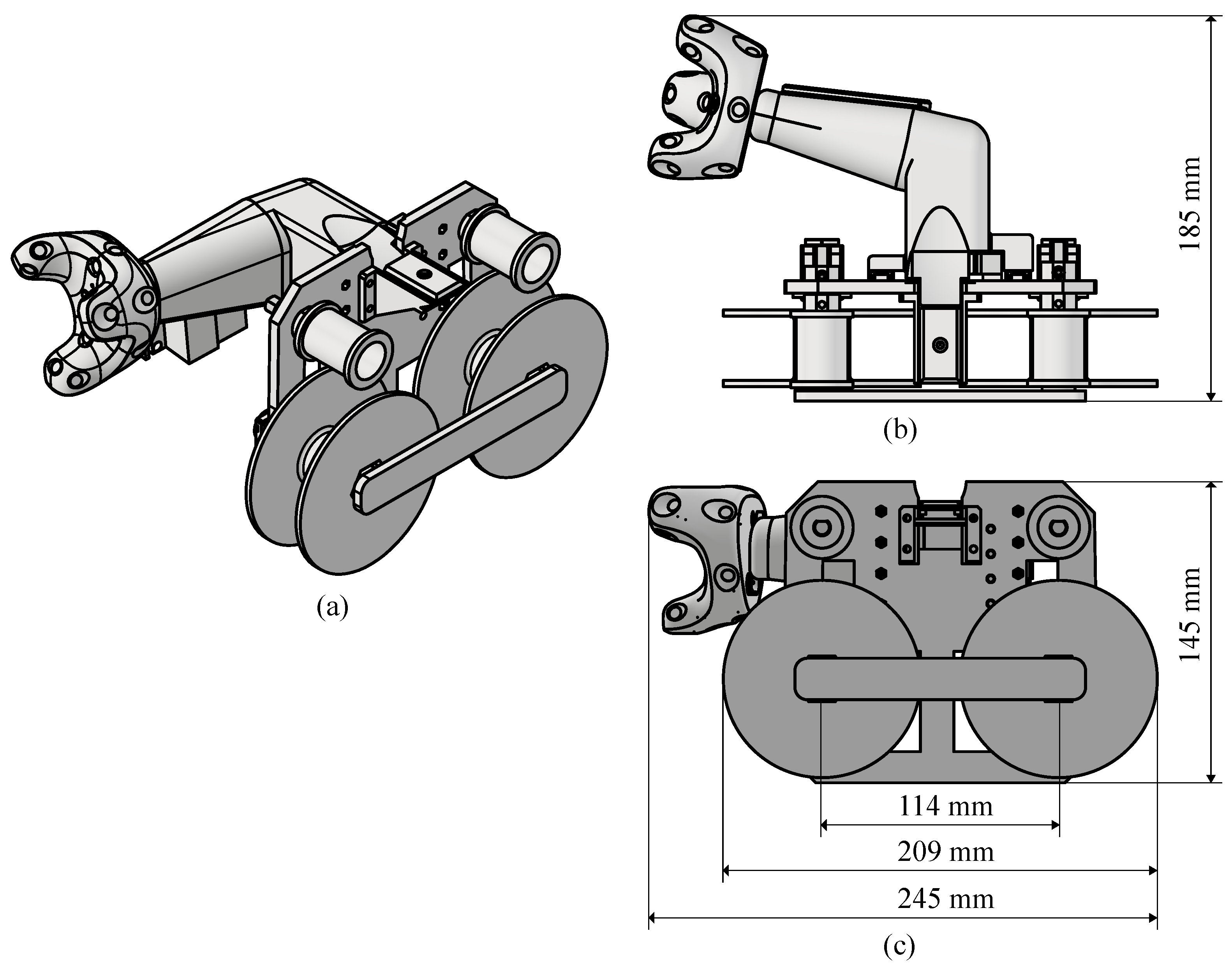
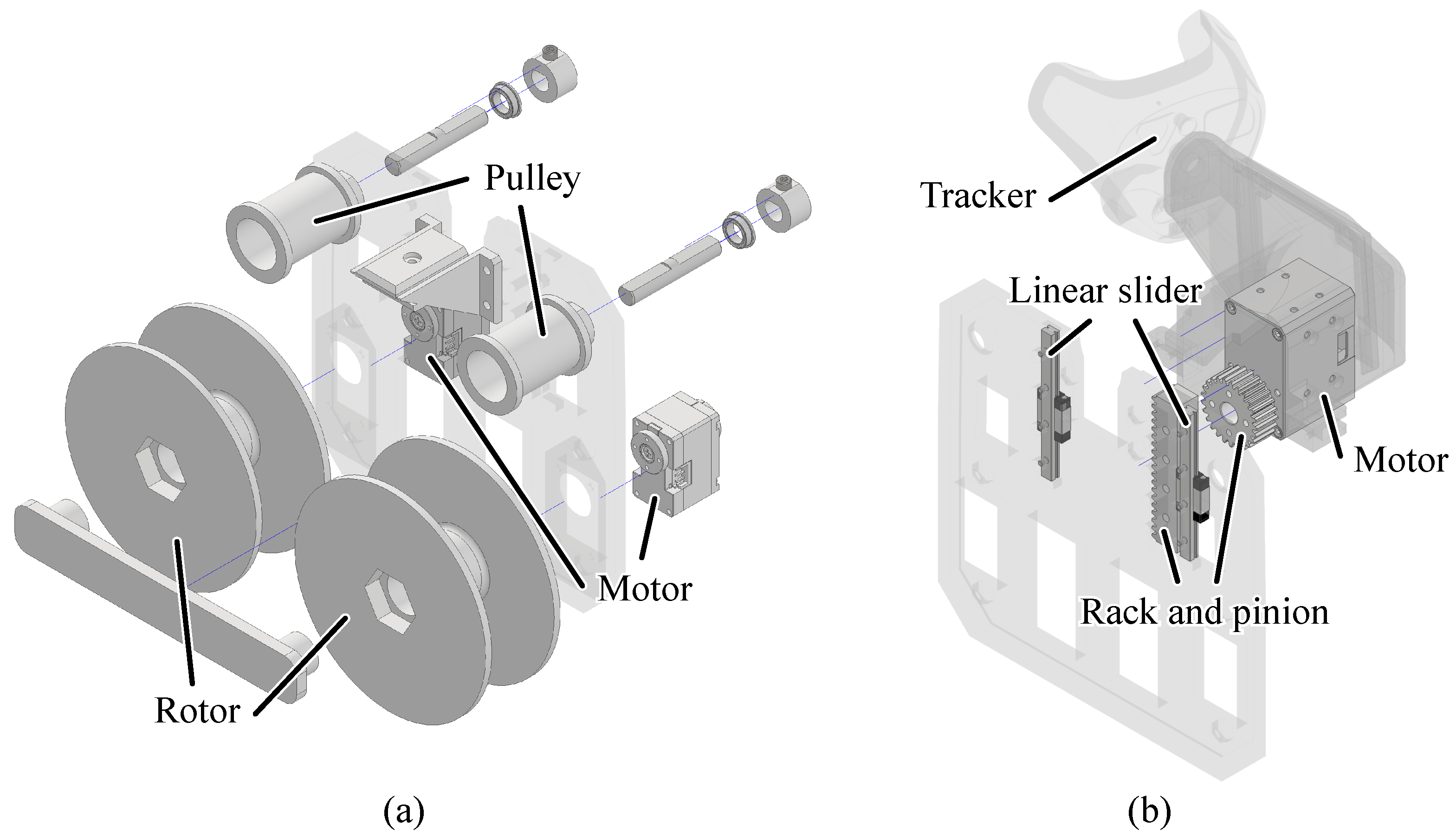
2.2. Hardware Design

The appropriate number of materials to attach to the tape was examined. To present a diverse range of tactile sensations, it is desirable to increase the number of materials mounted on the device. However, due to constraints on dimensions and weight, the number of materials that can be mounted is limited. Previous studies evaluating and analyzing the perceptual characteristics of various real materials, such as wood, paper, fur, and fabric [23,24], utilized 35 and 36 types of materials, respectively. These can be interpreted as examples of efficient numbers for expressing the tactile diversity of the material. The maximum number of materials that can be attached to the tape is 30, which is close to the number of these examples.
Next, the appropriate length of the materials to attach to the tape was considered. Although longer materials are preferable, increasing their length reduces the number of materials that can be mounted. In the study by [24], the target material for stroking was a square with a side length of 140 mm. Additionally, the authors of this paper traced materials with their fingers to evaluate the tactile sensations and found that the typical finger movement distance was approximately 100 mm. Based on these findings, the length of each material was set to 150 mm.
A schematic diagram of the tape for attaching materials is shown in Figure 2. The tape used was made of polyvinyl chloride, with a thickness of 0.08 mm. The 100 mm sections at both ends of the tape cannot reach the finger placement area and, therefore, remain free of materials. A gap of 5.0 mm was also included between adjacent materials. When this tape is wound onto a motor-driven rotor, the arrangement of components is designed to prevent interference between the rolled tape and other parts.
The constructed device switching a number of materials is shown in Figure 3, and the CAD drawing of the device is provided in Figure 4. The weight of the device without materials is 475 g. It is not intended to be used continuously for long periods of time; its weight is not light, and prolonged use is likely to cause fatigue. Although it is difficult to radically reduce weight, weight reductions associated with design optimization can be expected. The tape moves in the horizontal direction, as this is considered more natural when stroking objects with the finger. This choice is supported by previous studies, such as the research by Callier et al. [25], where more trials were conducted in the horizontal direction compared to the vertical direction.
When stroking materials with the finger, the finger’s posture tends to be tilted downwards. To accommodate this natural finger posture, a slope is incorporated at the location where the index finger of the grip is placed. This design allows the user to trace the material with a tilted finger posture.
The details of the tape winding/unwinding mechanism and the device’s grip section are shown in Figure 5. The lower rotor is rotated by a small geared motor (Dynamixel XC-330-T288-T, ROBOTIS Co. Ltd., Seoul, Republic of Korea), which is responsible for winding and unwinding the tape. The upper pulley rotates smoothly in response to the tape’s movement, supported by bearings mounted on the shaft. The bearings are fixed between the pulley and a stopper to ensure stable rotation.
The grip section is vertically movable by 55 mm through a rack-and-pinion linear motion mechanism. The grip moves smoothly in the vertical direction with the help of left and right sliders. This mechanism is used to present the contact and non-contact states between the material and the finger, as described in the subsequent sections.
A high-torque geared motor (Dynamixel XM-430-W350, ROBOTIS Co. Ltd., Seoul, Republic of Korea) is used to drive the linear motion mechanism. Additionally, to track the position of the tactile display, a tracker (VIVE Tracker, HTC Corporation, Taoyuan, Taiwan) is mounted at the end of the handle. This setup allows the precise tracking of the grip’s position during operation. Moreover, a force sensor (USL06-H5, Tec Gihan Co., Ltd., Kyoto, Japan) installed under the finger rest measures the force applied and enables contact determination.

2.3. Control Software

To present material properties corresponding to the virtual object’s texture, the following three functions are to be considered necessary:
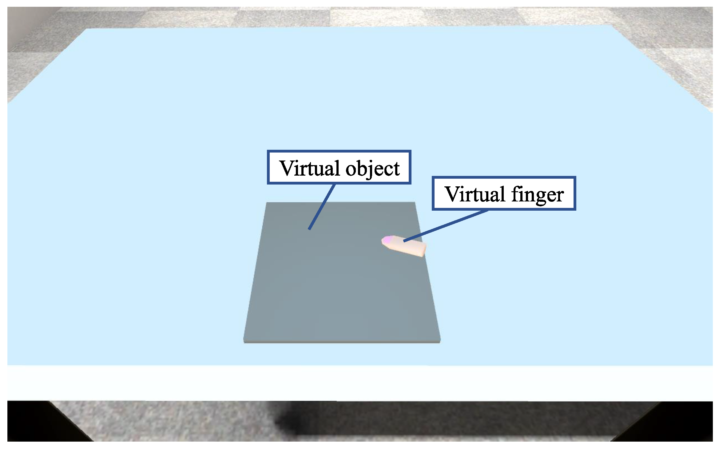
  • Reproduction of stroking motion: When the virtual finger is in contact with the virtual object, the material is moved horizontally in accordance with the speed of the stroking motion. The roughness of the object’s surface is perceived through the vibrations produced by the skin during the stroking motion [26,27]. Thus, reproducing the stroking motion is considered a necessary function for presenting material properties accurately.
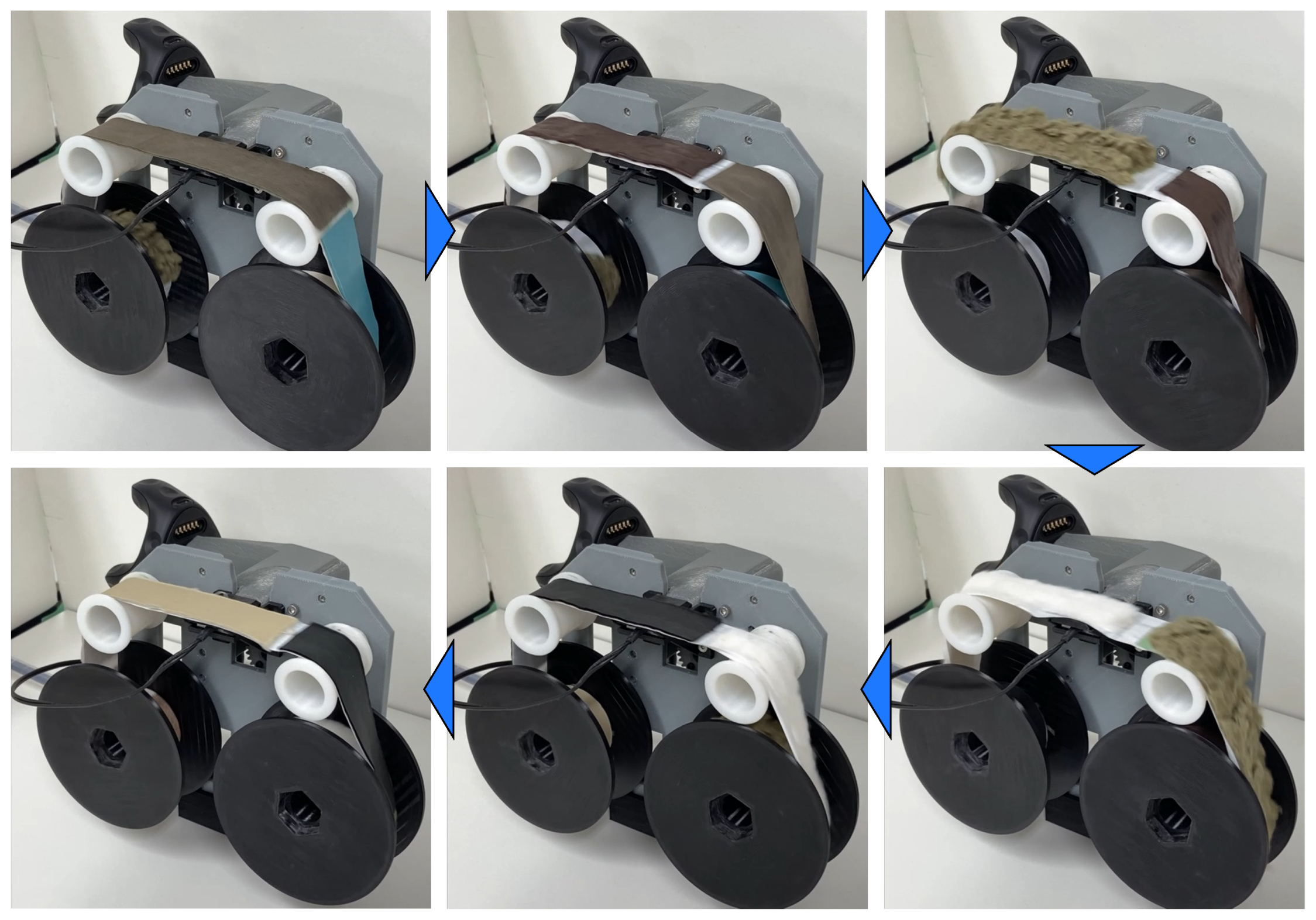
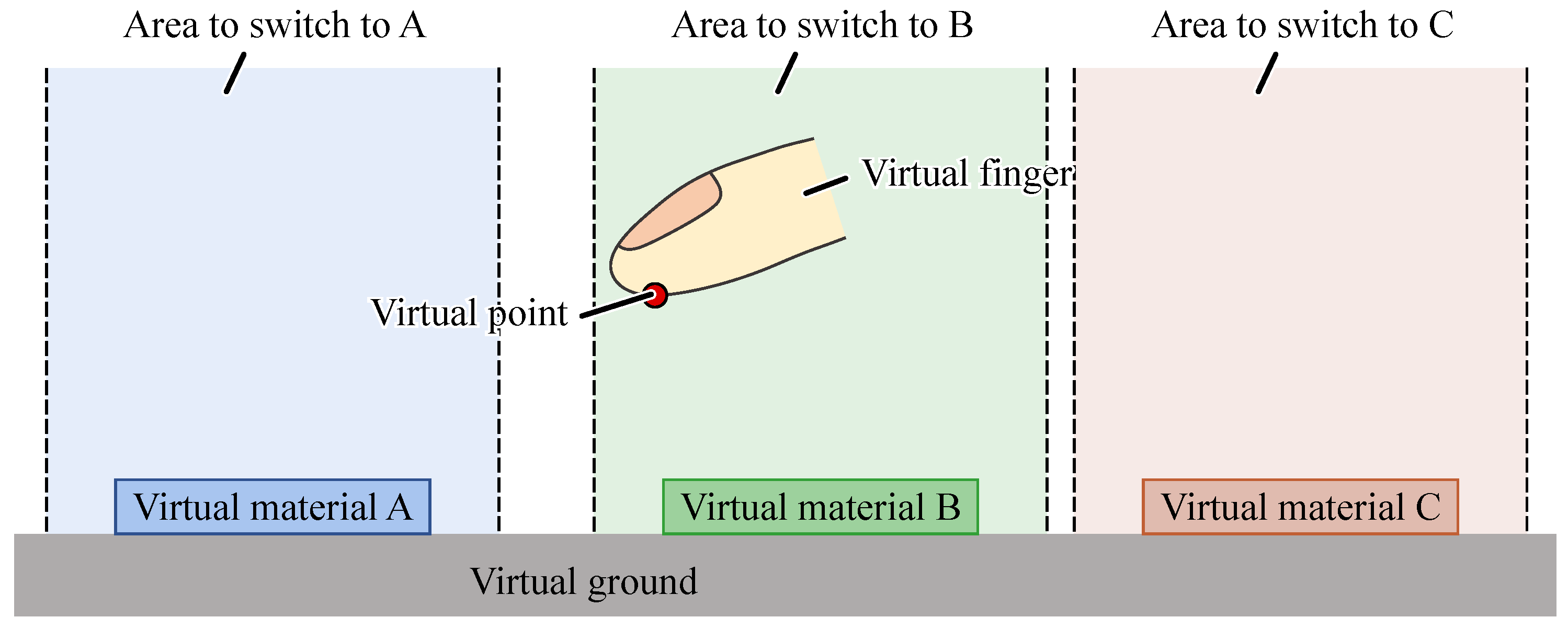
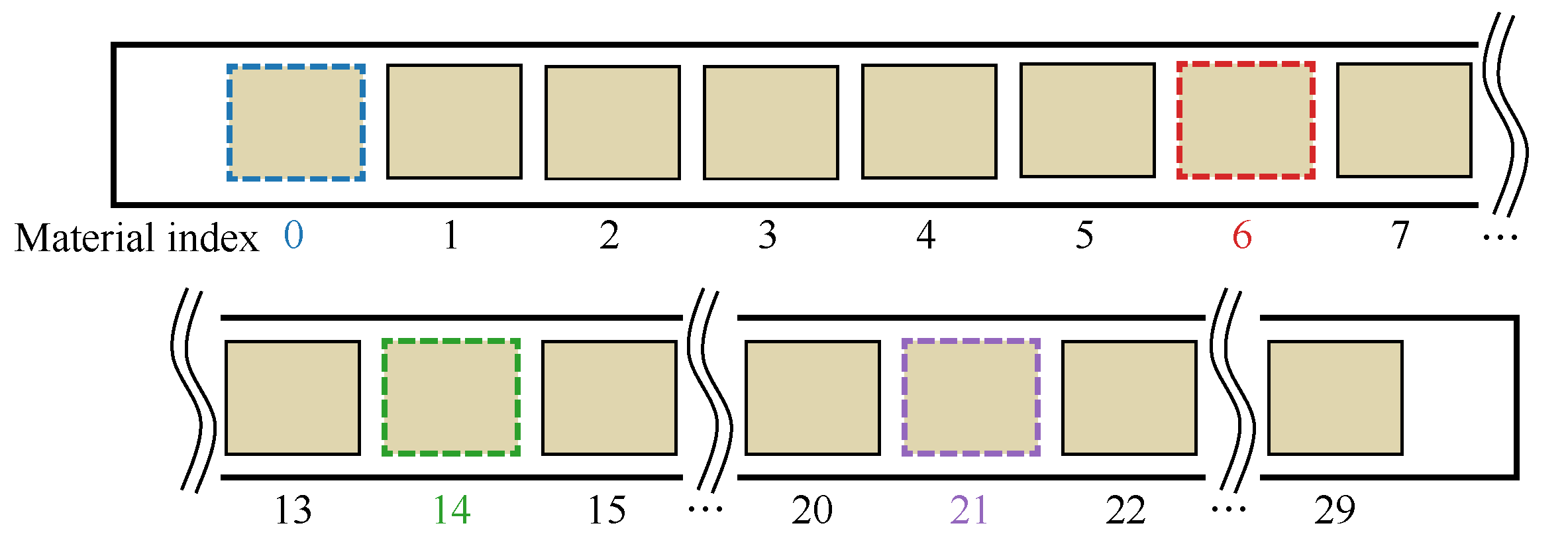
  • Switching of target material: When the virtual finger is not in contact with the virtual object, the system moves the material that the finger would next contact directly under the finger. This feature is essential for presenting material properties simultaneously with the contact of the virtual object. In the device created for this study, multiple materials are placed on a single tape. If the position of the next material to be touched is far from the current material, there will be a delay in bringing the actual material to the position under the finger. Therefore, by simply predicting the material, the user will know they will touch it next before actually touching it, and preparing the corresponding actual material in advance, the material’s characteristics can be presented without delay.
  • Presentation of contact and non-contact states between the material and the finger: The grip mechanism moves vertically in sync with the contact and non-contact states of the virtual finger and the virtual object. This ensures that the tactile sensation of contact or non-contact is consistent between the real and virtual environments.

2.3.1. Stroking Motion Reproduction

The stroking speed is reproduced by moving the tape in the opposite direction to the stroking motion. First, the device’s speed is calculated from the position data obtained from the tracker attached to the device. The virtual finger is then displayed on the screen to match the device’s movement. The speed of the tape v tape is the left–right component of the device’s speed when in contact with the virtual object. To realize the tape’s speed, the rotation speed of the motors is controlled. The relationship between v tape , the winding radius R, and the rotation speed of the winding motor ω roll is as follows:
ω roll = v tape / R .
Here, R can be estimated from the radius r of the rotor, the number of windings n, and the average thickness t of the material using the following formula:
R = r + n t .
Since the torque on the winding motor increases with the amount of material wound, there is a possibility of overheating. To mitigate this, the feed motor rotates in the same direction as the winding motor to reduce the load on the winding motor. During this process, the speed of the feed motor is kept low enough to prevent slack in the tape. The rotational speed of the feed motor ω send is controlled as follows:
ω send = α R .
Here, α is a constant adjusted experimentally.
In a study measuring the finger speed while stroking various materials [25], the average stroking speed was found to be approximately 100 mm/s under the fastest conditions. Based on this, the device is designed to reproduce a maximum stroking speed of 100 mm/s.

2.3.2. Target Material Switching

When the target material switches, the target rotation angle for the motor is obtained from the recorded data that correspond the motor’s rotation angle with the position of the material’s center on the tape. The motor is then commanded to rotate relative to the target angle to switch the material. As shown in Figure 6, a region for switching the target material is defined in the virtual space. When the virtual finger, displayed on the screen, enters one of these regions, the material is switched to the corresponding one. The size of each region is determined based on the characteristics of the application being developed and the distance between the material specified by the neighboring region on the tape.

2.3.3. Contact and Non-Contact Presentation

The grip moves up and down to match the contact and non-contact states between the virtual finger and the virtual object, ensuring that the states of contact and non-contact between the finger and the object are consistent between the real and virtual environments. The linear motion mechanism is implemented using a rack and pinion system, as shown in Figure 5b. When the virtual finger and the virtual object are in a non-contact state, the grip rises, and the real material and the finger are in a non-contact state, similarly to the virtual environment. When the virtual finger contacts the virtual object, the grip descends, and the real material and the finger make contact.

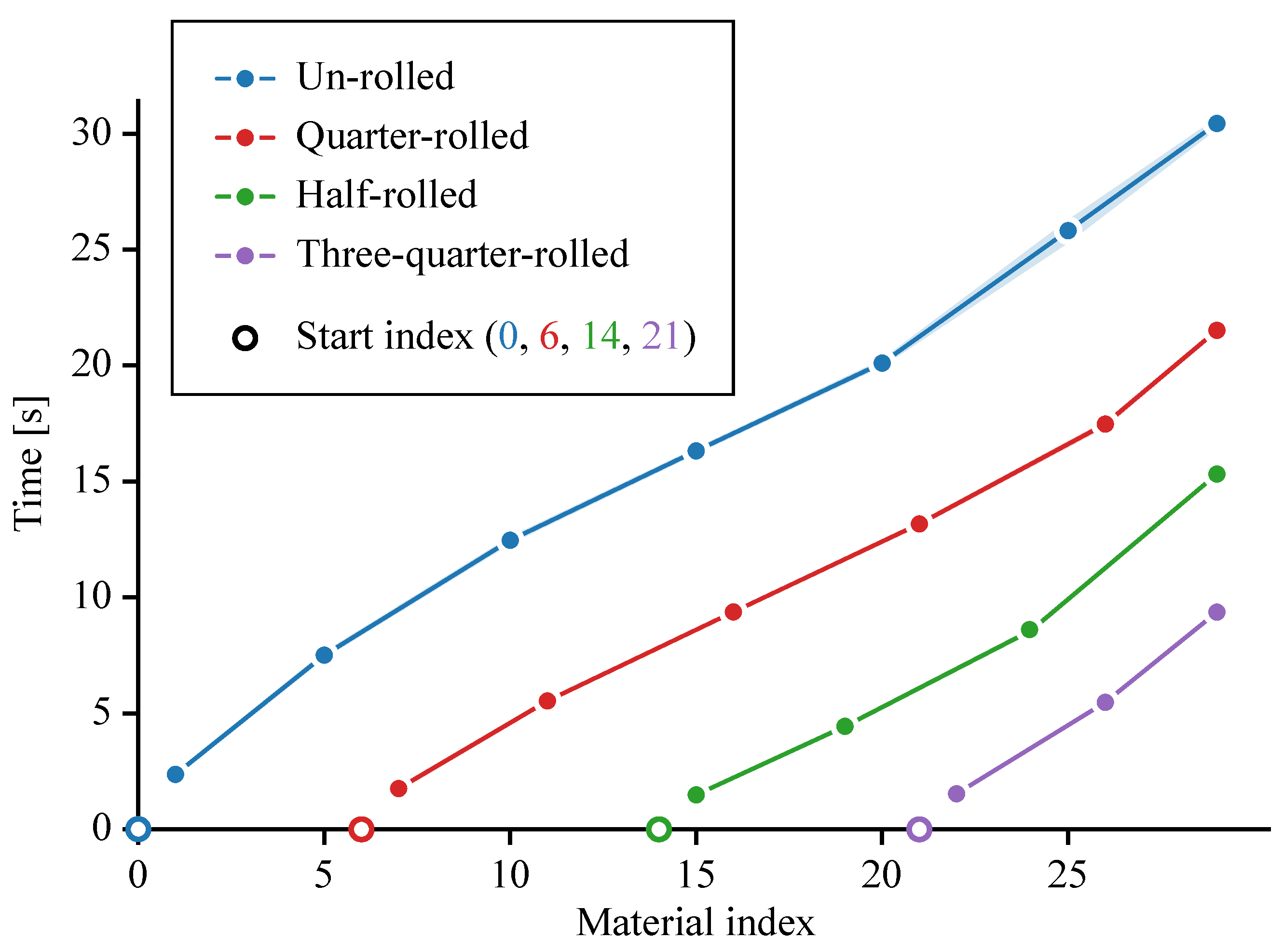
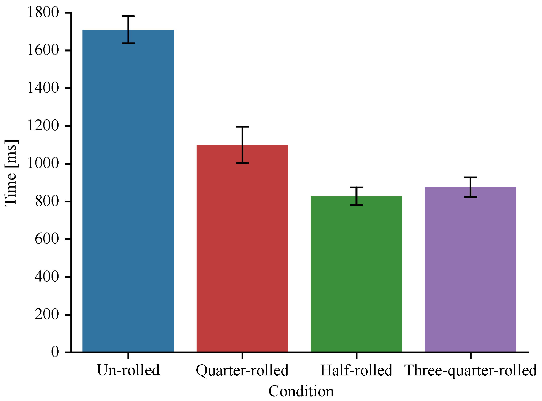
3. Experiment 1: Measurement of Time Required for Material Switching

3.1. Objective

The objective of Experiment 1 is to clarify the switching time of materials, which is a constraint of the proposed method. If the switching time is too long, it may undermine the enjoyment and immersion of the VR content. Therefore, this knowledge is an important factor to consider in the design of applications using this method.

3.2. Experimental Conditions

The experimental conditions are the material to switch to and the initial winding amount of the rotor. The material to switch to is the material adjacent to the starting material, the material at the edge of the tape (index = 29), or any material located away, in multiples of five, from the starting material. The initial winding amounts are as follows: unrolled (index = 0), quarter-rolled (index = 6), half-rolled (index = 14), and three-quarter-rolled (index = 21) conditions. A diagram of the materials to switch to when the starting material is unwound is shown in Figure 7.

3.3. Experimental Procedure

The winding of the tape was controlled via the current control, and the motor was always driven at 80% of its maximum current. The time measurement began as soon as rotation started and ended when the target angle was reached. Since material switching was performed without contact between the finger and the material, the measurements were taken without pressing the tape with the finger. Nine trials were performed for each condition.

3.4. Results

Figure 8 shows the average switching time for nine trials under each condition. The required time generally increased linearly. The linear regression analysis examines whether a single linear approximation can effectively explain the data from nine trials. Table 2 summarizes the statistical results for the different rolling conditions. The R 2 values indicate the goodness of fit for each condition, while the p-values are used to assess the statistical significance of the linear approximation. Switching between the materials at both ends took about 30 s.
Figure 9 shows the average switching time for nine trials when switching to the adjacent material. The switching time relative to the adjacent material was longest in the unrolled condition and shortest in the half-rolled condition, about half of the time taken in the unwound condition.

4. Experiment 2: Material Discrimination

4.1. Objective

Experiment 2 investigates the effectiveness of the developed system’s features of switching between materials and reproducing relative stroking. Specifically, we investigate whether the discrimination performance of the material when touched without stroking in the proposed virtual environment is close to that in the real environment without stroking. We also investigate whether the discrimination performance in the virtual environment with stroking is close to that in a real environment with stroking.

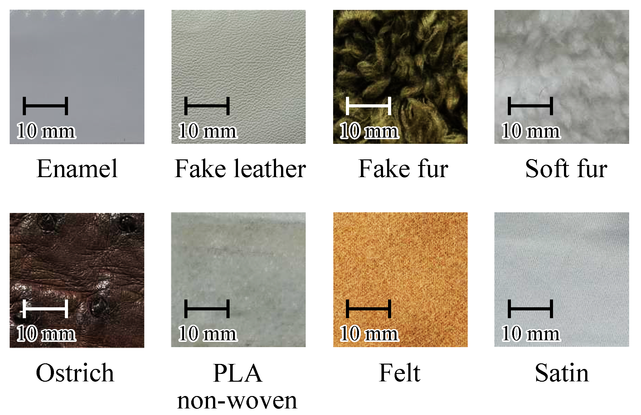
4.2. Experimental Conditions

The experimental conditions include four scenarios: exploring materials in a virtual environment (“Virtual–Dynamic”), exploring materials haptically in a real environment (“Real–Dynamic”), touching materials in a virtual environment without haptic exploration (“Virtual–Static”), and touching materials in a real environment without haptic exploration (“Real–Static”). The materials to be touched are the eight types shown in Figure 10. A wide variety of materials were selected: It was assumed that five of the eight materials (enamel, fake leather, poly non-woven, felt, and satin) had few features such as surface irregularities and were difficult to identify via static contact alone, but tactile exploration could improve detection performance. Ten male participants in the experiment were aged between 22 and 25 years.

4.3. Experimental Procedure

At the beginning of the experiment, participants touched all eight materials for a few minutes without looking to learn the index number of the material.
In the “Virtual-Dynamic” condition, as shown in Figure 11, one of the eight materials was presented as a gray virtual object, and the participants were asked to trace the object. They then identified the material they traced by its number, referencing the eight material samples shown in Figure 10. The virtual object and the virtual finger were displayed on a monitor placed in front of the participant. To prevent the participant from seeing the material presented by the device, a cover was placed over the material. The participants were instructed to trace the material in the left–right direction. Each material was presented once in a random order per set. Three trials for each material were performed.
In the “Real–Dynamic” condition, the participants wore blindfolds while stroking one of the eight materials. After removing the blindfold, they identified the material they had traced by number, referencing the material samples. The experimenter guided the participant’s finger to the central position of the material they were to trace. The participants were instructed to trace the material in the left–right direction. Three trials for each material were performed.
In the “Virtual–Static” and “Real–Static” conditions, the procedure was the same as the environment exploration condition, except that stroking was prohibited. The participants were instructed to press their fingers against the materials and not to stroke them horizontally. Three trials for each material were performed.
In each condition, participants were allowed to touch the materials for as long as they wanted. After providing an answer, participants were allowed to touch the material again and correct their answer if necessary. A total of ten participants took part in the experiment.

4.4. Results

The confusion matrix showing the materials presented and the materials guessed by the participants in each condition is shown in Figure 12. The results show similar trends between the virtual and real environment conditions. Some materials are more difficult to discriminate in the static condition without stroking than in the condition with stroking. This trend is similar for both real and virtual conditions.
Accuracy was compared under real and virtual conditions, as shown in Figure 13. Table 3 summarizes the results of the Wilcoxon signed-rank test and power analysis. The results showed no statistically significant difference between real and virtual scenarios in the dynamic and static conditions, respectively.

5. Discussion

5.1. Material Switching Time

From the results of Experiment Section 3, we discuss the characteristics of the material switching time in this device. As shown in Figure 8, the time required to switch materials increased approximately linearly. For example, in the unwound condition, it took about 15 s to switch to the material in the center of the tape (Index = 14) and about 30 s to switch to the material at the end (Index = 29), indicating a linear trend. However, this increase is not perfectly linear; it is slightly convex for indexes less than 14 and slightly concave for indexes greater than 14. The slope was smallest around Index 14, and it increased as the material index moved away from the center. This suggests that switching between materials near the center of the tape takes less time. In fact, as shown in Figure 9, the time to switch to adjacent materials was about half of the time required in the unwound condition.
The observed non-linearity is likely due to the current control of the take-up motor. The tape speed v tape is given by the product of the rotational radius R of the take-up rotor and the angular velocity ω roll , as expressed in Equation (1). As the amount of material wound increases, R increases, but since the motor is controlled by the current, ω roll decreases. For indexes less than 14, the dominant factor controlling the tape speed is R, while for indexes greater than 14, it is ω roll , and the tape may have reached its highest speed at index 14.
We discuss methods for reducing the material switching time. One challenge of this device is that it takes a long time to switch materials. As shown in Figure 8, in the condition where the longest switching time occurs, it takes 30 s. Such long waiting times may impair the enjoyment and immersion in VR content, so improvements are necessary.
From Figure 9, it can be seen that the time to switch to adjacent materials was halved when switching to materials at the center of the tape. This suggests that when using this device in VR content, placing materials corresponding to virtual objects near the center of the tape can prevent delays in switching when these objects are closer to each other than others in the virtual space. Additionally, by reducing the length of materials for smaller virtual objects, it may be possible to reduce switching times.
In some content, it may be possible to design effects that hide switching times. For example, in a VR zoo, virtual animals could escape from the player while material switching is occurring, preventing the virtual finger from contacting the animal during the switching process.

5.2. Increase in the Traceable Distance of Materials

Here, we discuss methods for increasing the traceable distance of materials. Another challenge of this device is the finite length of the material. The length of the material attached to the tape is 150 mm, which is not short, but for large virtual objects, there is a concern that the edge of the material will be reached during stroking.
By setting the tape’s speed slower than the virtual finger’s speed, it is possible to trace materials for a longer distance. While this may cause discomfort due to the discrepancy in speed, Whitmire et al. reported that a 20% slower presented stroking speed did not affect the realism evaluation [13]. Thus, it is believed that humans are not very sensitive to the discrepancy between finger speed obtained from vision and finger speed obtained from touch. Therefore, by reducing the tape’s speed within a range that does not cause discomfort, the traceable distance can be increased.
By adjusting the position of the tape when the material switches, the maximum traceable distance can be achieved. Currently, when the material switches, the motor rotates so that the center of the target material is positioned at the place where the virtual finger is placed. In this case, if the finger touches the edge of the virtual object, the traceable distance is limited to half the length of the material. Therefore, we consider calculating the position of the finger relative to the virtual object when the finger is not in contact with the object and moving the tape to a position where the traceable distance is maximized.

5.3. Methods for Enhancing Texture Variety

We discuss methods for increasing the variety of material textures without increasing the number of materials attached to the device. Currently, this device can hold up to 30 types of materials when the length of each material is 150 mm. However, there may be situations where we want to provide a larger variety of textures. Increasing the number of materials beyond this limit is difficult due to dimensional and weight constraints. Therefore, a method to increase the number of possible textures without increasing the number of materials is required.
Using visual illusions, it is expected that a greater variety of textures can be expressed without increasing the number of materials used. It has been reported that the perceived tactile sensation changes depending on the visual information present even though the tactile sensation is tactilely the same [28,29]. Such a method is called pseudo-haptics and is expected to expand the variation in the perceived material by using such methods together. Additionally, the method of modulating the tactile sensation of a material by using mechanical vibrations [8,9] can also be used in combination with the method we propose here, and it is expected to expand the variations in the perceived sensation of the material.

6. Conclusions

In this paper, we developed and evaluated MateREAL Touch, a handheld haptic display that enables the realistic presentation of a wide range of material textures in virtual environments. The system utilizes a rolling tape mechanism to store and dynamically switch between up to 30 real materials, allowing users to experience natural stroking sensations. Through a series of experiments, the system’s basic performance in terms of material switching time and its subjective material identification capability under static and dynamic touch conditions were assessed. Our results demonstrated that MateREAL Touch effectively reproduces texture perception comparable to real-world experiences when users engage in stroking motions. Regarding material switching, the minimum time required to switch to an adjacent material was approximately 800 ms. In the material discrimination experiment, the discrimination accuracy in the VR environment was comparable to that in the real environment under both static and dynamic conditions, confirming that stroking motions significantly improve material recognition accuracy in both settings. These results validate the ability of our proposed system to convey realistic texture perception in virtual environments.

Author Contributions

Conceptualization, K.M. and H.N.; methodology, K.M. and H.N.; software, K.M.; validation, K.M. and H.N.; formal analysis, K.M. and H.N.; investigation, K.M. and H.N.; resources, H.N., Y.T. and Y.Y.; data curation, K.M. and H.N.; writing—original draft preparation, K.M.; writing—review and editing, H.N., Y.T. and Y.Y.; visualization, K.M. and H.N.; supervision, H.N. and Y.Y.; project administration, H.N.; funding acquisition, H.N. All authors have read and agreed to the published version of the manuscript.

Funding

This work was supported by JSPS KAKENHI under grant number JP20K04398.

Institutional Review Board Statement

All subjects gave their informed consent for inclusion before they participated in the study. This study was conducted according to the guidelines of the Declaration of Helsinki and approved by the ethical review board of the Faculty of Engineering of Kobe University (protocol code 02-13 and 16 September 2020).

Informed Consent Statement

Informed consent was obtained from all participants involved in the study.

Data Availability Statement

The original contributions presented in this study are included in the article. Further inquiries can be directed to the corresponding author.

Conflicts of Interest

The authors declare no conflicts of interest.

References

  1. Choi, S.; Kuchenbecker, K.J. Vibrotactile display: Perception, technology, and applications. Proc. IEEE 2012, 101, 2093–2104. [Google Scholar] [CrossRef]
  2. Okamoto, S.; Nagano, H.; Yamada, Y. Psychophysical dimensions of tactile perception of textures. IEEE Trans. Haptics 2012, 6, 81–93. [Google Scholar] [CrossRef] [PubMed]
  3. Konyo, M.; Yamada, H.; Okamoto, S.; Tadokoro, S. Alternative Display of Friction Represented by Tactile Stimulation without Tangential Force. In Proceedings of the EuroHaptics 2008, Madrid, Spain, 11–13 June 2008. [Google Scholar]
  4. Provancher, W.R.; Sylvester, N.D. Fingerpad skin stretch increases the perception of virtual friction. IEEE Trans. Haptics 2009, 2, 212–223. [Google Scholar] [CrossRef] [PubMed]
  5. Iizuka, S.; Nagano, H.; Konyo, M.; Tadokoro, S. Toward multi-finger haptic interaction: Presenting vibrotactile stimuli from proximal phalanges to fingertips. In Proceedings of the 2017 IEEE/SICE International Symposium on System Integration (SII), Taipei, Taiwan, 11–14 December 2017; pp. 905–911. [Google Scholar]
  6. Lo, J.Y.; Huang, D.Y.; Sun, C.K.; Hou, C.E.; Chen, B.Y. RollingStone: Using single slip taxel for enhancing active finger exploration with a virtual reality controller. In Proceedings of the 31st Annual ACM Symposium on User Interface Software and Technology, Berlin, Germany, 14–17 October 2018; pp. 839–851. [Google Scholar]
  7. Choi, I.; Ofek, E.; Benko, H.; Sinclair, M.; Holz, C. Claw: A multifunctional handheld haptic controller for grasping, touching, and triggering in virtual reality. In Proceedings of the 2018 CHI Conference on Human Factors in Computing Systems, Montreal, QC, Canada, 21–27 April 2018; pp. 1–13. [Google Scholar]
  8. Asano, S.; Okamoto, S.; Matsuura, Y.; Nagano, H.; Yamada, Y. Vibrotactile display approach that modifies roughness sensations of real textures. In Proceedings of the 2012 IEEE RO-MAN: The 21st IEEE International Symposium on Robot and Human Interactive Communication, Paris, France, 9–13 September 2012; pp. 1001–1006. [Google Scholar]
  9. Asano, S.; Okamoto, S.; Yamada, Y. Vibrotactile stimulation to increase and decrease texture roughness. IEEE Trans. Hum.-Mach. Syst. 2014, 45, 393–398. [Google Scholar] [CrossRef]
  10. Lee, C.J.; Tsai, H.R.; Chen, B.Y. HairTouch: Providing Stiffness, Roughness and Surface Height Differences Using Reconfigurable Brush Hairs on a VR Controller. In Proceedings of the 2021 CHI Conference on Human Factors in Computing Systems, Online, 8–13 May 2021; pp. 1–13. [Google Scholar]
  11. Ochiai, Y.; Hoshi, T.; Rekimoto, J.; Takasaki, M. Diminished haptics: Towards digital transformation of real world textures. In Proceedings of the International Conference on Human Haptic Sensing and Touch Enabled Computer Applications, Versailles, France, 24–26 June 2014; Springer: Berlin/Heidelberg, Germany, 2014; pp. 409–417. [Google Scholar]
  12. Araujo, B.; Jota, R.; Perumal, V.; Yao, J.X.; Singh, K.; Wigdor, D. Snake charmer: Physically enabling virtual objects. In Proceedings of the TEI’16: Tenth International Conference on Tangible, Embedded, and Embodied Interaction, Eindhoven, The Netherlands, 14–17 February 2016; pp. 218–226. [Google Scholar]
  13. Whitmire, E.; Benko, H.; Holz, C.; Ofek, E.; Sinclair, M. Haptic revolver: Touch, shear, texture, and shape rendering on a reconfigurable virtual reality controller. In Proceedings of the 2018 CHI Conference on Human Factors in Computing Systems, Montreal, QC, Canada, 21–26 April 2018; pp. 1–12. [Google Scholar]
  14. Mercado, V.; Marchal, M.; Lécuyer, A. Entropia: Towards infinite surface haptic displays in virtual reality using encountered-type rotating props. IEEE Trans. Vis. Comput. Graph. 2019, 27, 2237–2243. [Google Scholar] [CrossRef] [PubMed]
  15. Degraen, D.; Reindl, A.; Makhsadov, A.; Zenner, A.; Krüger, A. Envisioning haptic design for immersive virtual environments. In Proceedings of the Companion Publication of the 2020 ACM Designing Interactive Systems Conference, Eindhoven, The Netherlands, 6–10 July 2020; pp. 287–291. [Google Scholar]
  16. Takizawa, N.; Yano, H.; Iwata, H.; Oshiro, Y.; Ohkohchi, N. Encountered-type haptic interface for representation of shape and rigidity of 3d virtual objects. IEEE Trans. Haptics 2017, 10, 500–510. [Google Scholar] [CrossRef] [PubMed]
  17. Huang, H.Y.; Ning, C.W.; Wang, P.Y.; Cheng, J.H.; Cheng, L.P. Haptic-go-round: A surrounding platform for encounter-type haptics in virtual reality experiences. In Proceedings of the 2020 CHI Conference on Human Factors in Computing Systems, Honolulu, HI, USA, 25–30 April 2020; pp. 1–10. [Google Scholar]
  18. Horie, A.; Saraiji, M.Y.; Kashino, Z.; Inami, M. Encounteredlimbs: A room-scale encountered-type haptic presentation using wearable robotic arms. In Proceedings of the 2021 IEEE Virtual Reality and 3D User Interfaces (VR), Virtual Conference, 27 March–3 April 2021; pp. 260–269. [Google Scholar]
  19. Mercado, V.R.; Marchal, M.; Lécuyer, A. “Haptics On-Demand”: A Survey on Encountered-Type Haptic Displays. IEEE Trans. Haptics 2021, 14, 449–464. [Google Scholar] [CrossRef] [PubMed]
  20. Dongye, X.; Weng, D.; Jiang, H.; Feng, L. A modular haptic agent system with encountered-type active interaction. Electronics 2023, 12, 2069. [Google Scholar] [CrossRef]
  21. Yamaguchi, S.; Shionoiri, H.; Nakamura, T.; Kajimoto, H. An encounter type VR system aimed at exhibiting wall material samples for show house. In Proceedings of the 2018 ACM International Conference on Interactive Surfaces and Spaces, Tokyo, Japan, 25–28 November 2018; pp. 321–326. [Google Scholar]
  22. Chan, V.H.; Chan, Y.C.; Peng, P.H.; Cheng, L.P. TexelBlocks: Dynamic Surfaces for Physical Interactions. In Proceedings of the Extended Abstracts of the 2021 CHI Conference on Human Factors in Computing Systems, New York, NY, USA, 8–13 May 2021; pp. 1–5. [Google Scholar]
  23. Yokosaka, T.; Kuroki, S.; Watanabe, J.; Nishida, S. Linkage between free exploratory movements and subjective tactile ratings. IEEE Trans. Haptics 2016, 10, 217–225. [Google Scholar] [CrossRef] [PubMed]
  24. Nagano, H.; Okamoto, S.; Yamada, Y. Modeling semantically multilayered affective and psychophysical responses toward tactile textures. IEEE Trans. Haptics 2018, 11, 568–578. [Google Scholar] [CrossRef] [PubMed]
  25. Callier, T.; Saal, H.P.; Davis-Berg, E.C.; Bensmaia, S.J. Kinematics of unconstrained tactile texture exploration. J. Neurophysiol. 2015, 113, 3013–3020. [Google Scholar] [CrossRef] [PubMed]
  26. Lederman, S.J. Tactile roughness of grooved surfaces: The touching process and effects of macro-and microsurface structure. Percept. Psychophys. 1974, 16, 385–395. [Google Scholar] [CrossRef]
  27. Cascio, C.J.; Sathian, K. Temporal cues contribute to tactile perception of roughness. J. Neurosci. 2001, 21, 5289–5296. [Google Scholar] [CrossRef] [PubMed]
  28. Punpongsanon, P.; Iwai, D.; Sato, K. Softar: Visually manipulating haptic softness perception in spatial augmented reality. IEEE Trans. Vis. Comput. Graph. 2015, 21, 1279–1288. [Google Scholar] [CrossRef] [PubMed]
  29. Ujitoko, Y.; Ban, Y.; Hirota, K. Modulating fine roughness perception of vibrotactile textured surface using pseudo-haptic effect. IEEE Trans. Vis. Comput. Graph. 2019, 25, 1981–1990. [Google Scholar] [CrossRef] [PubMed]
Figure 1. Concept of MateREAL Touch capable of presenting the tactile sensation of various material textures using a number of real rolled materials.
Electronics 14 01250 g001
Figure 2. Schematic of the tape for pasting materials.
Electronics 14 01250 g002
Figure 3. Time lapse of a developed tactile device switching between different materials.
Electronics 14 01250 g003
Figure 4. CAD design of the device. (a) Perspective view. (b) Top view. (c) Front view.
Electronics 14 01250 g004
Figure 5. Detailed view of the device. (a) Rotary mechanism to roll up materials. (b) Grip section that can move up and down via a rack and pinion mechanism.
Electronics 14 01250 g005
Figure 6. Defined area in virtual space to switch to the target material. When a virtual finger enters the area, the device switches to the target material.
Electronics 14 01250 g006
Figure 7. Materials to switch to under the condition that the starting material is index = 0. Each dashed box represents a target material in four different conditions.
Electronics 14 01250 g007
Figure 8. The average of the nine trials of the time required to switch materials for different conditions relative to different numbers of pre-rolled materials.
Electronics 14 01250 g008
Figure 9. The average of nine trials of the time taken to switch to one neighboring material in each pre-rolled condition.
Electronics 14 01250 g009
Figure 10. Eight materials used in Experiment 2.
Electronics 14 01250 g010
Figure 11. Virtual object and finger displayed on a monitor. When the virtual finger touches the virtual object, any of eight materials is presented.
Electronics 14 01250 g011
Figure 12. Confusion matrices of the presented and answered materials in each condition. (a) Real–Static condition, (b) Virtual–Static condition, (c) Real–Dynamic condition, and (d) Virtual–Dynamic condition.
Electronics 14 01250 g012
Figure 13. Comparison of the accuracy between four conditions. “n.s.” indicates no statistically significant differences ( p > 0.05 ) between conditions based on the Wilcoxon signed-rank test.
Electronics 14 01250 g013
Table 1. Haptic devices presenting material sensation by switching real materials.
TypeThe Number of MaterialsReference
Grounded7[12]
Grounded3 (possible to increase)[14]
Grounded4[22]
Grounded4[21]
Handheld4[13]
Handheld6[15]
Table 2. Statistical results of linear regression analysis under different conditions for different numbers of pre-rolled materials.
Condition R 2 p-Value
Unrolled0.99 7.3 × 10 7
Quarter rolled0.99 1.3 × 10 5
Half-rolled0.980.010
Three-quarter rolled0.990.049
Table 3. Results of the Wilcoxon signed-rank test and power analysis.
Comparisonp-ValueCohen’s d
Real–Static vs. Virtual–Static0.05200.2664
Real–Dynamic vs. Virtual–Dynamic0.21761.0000
Disclaimer/Publisher’s Note: The statements, opinions and data contained in all publications are solely those of the individual author(s) and contributor(s) and not of MDPI and/or the editor(s). MDPI and/or the editor(s) disclaim responsibility for any injury to people or property resulting from any ideas, methods, instructions or products referred to in the content.

