1. Introduction
Network function virtualization (NFV) plays a crucial role in addressing the limitations of current network architectures, particularly in terms of flexibility and agility. However, the rate at which central processing unit (CPU) performance improves has consistently lagged behind the rapid increase in network interface speeds [
1]. Additionally, in cloud network environments, it is highly desirable to allocate expensive CPU-based computing resources primarily to tenants rather than utilizing them for network packet processing. Consequently, an increasing number of VNFs are being offloaded to specialized hardware [
2], such as FPGAs.
To provide services to different network flows, which may originate from distinct tenants, it is common for these flows to share the same processing resources. Specifically, different flows are served individually, at different time intervals, by the same FPGA-offloaded VNF. To ensure isolation between tenants and deliver differentiated quality of service (QoS) to each tenant, it is essential to implement rate limiting on different flows within the FPGA.
The token bucket algorithm is a widely-used method for rate limiting network traffic. Each network flow is associated with a token bucket that functions as a storage container for tokens. Tokens are typically mapped to bytes, with each token representing one byte. At regular intervals, a predetermined number of tokens, determined by the configured rate limit for the specific network flow, are injected into the corresponding token bucket. The capacity of each token bucket is configurable and denotes the maximum number of tokens it can store.
When scheduling a packet from a specific network flow, the token count in the corresponding token bucket is assessed. If the available token count is sufficient, the packet is either directly scheduled (traffic shaping) or marked as green (traffic policing). Conversely, if the token count is insufficient, the packet is delayed until a sufficient number of tokens accumulate or is marked as red.
To achieve more fine-grained rate limiting, techniques such as the single-rate three-color marker [
3] and the two-rate three-color marker [
4] are employed. However, the basic principles underlying these methods are still those of the conventional token bucket.
However, current methods [
5,
6,
7,
8,
9,
10,
11,
12,
13] for implementing token buckets on FPGAs encounter significant challenges regarding scalability and precision. When providing rate-limiting services for multiple flows, the method presented in [
6,
8,
10,
11,
12] requires register resources that increase linearly with the number of flows to store information for different buckets. As a result, the number of supported flows is constrained. Although the method presented in [
5] uses block random access memory (BRAM) [
14] to store token bucket information, the read–write characteristics of BRAM necessitate that all buckets be injected with tokens at the same time interval. This, in turn, results in insufficient precision in the rate-limiting capabilities of configurable token buckets.
The existing challenges faced by current methods for implementing token bucket rate limiting on FPGAs revolve around the trade-off between the storage of token bucket configuration parameters and resource efficiency. Storing token bucket configuration parameters in resources such as LUTs and FFs ensures the fine-grained configuration and precise rate limiting of the token bucket. However, this approach compromises scalability. Conversely, storing these parameters in BRAM significantly enhances the scalability of the token bucket. Nevertheless, it poses difficulties in achieving a high granularity of rate limiting configurations, resulting in rate limiting outcomes that may deviate from the configured settings of the token bucket rate limiter.
The main idea of this paper is to utilize BRAMs to store token bucket configuration parameters while avoiding the token injection of the token bucket, which sets our approach apart from existing methods. We convert the token injection operation into calculating packet scheduling times based on the configured parameters, which can be summarized as the conversion of tokens to time. When the scheduling time arrives, the packet is then scheduled, ensuring the accuracy of scheduling. In this way, each packet, from being cached to being scheduled, only requires querying the corresponding token bucket’s configuration parameters once, utilizing just one read–write cycle of the BRAM. This allows the remaining read–write cycles of the BRAM to serve other packets. The Head Packet Scheduling Model further reduces the number of packets awaiting scheduling, alleviating scheduling pressures.
Our work can achieve large-scale queue rate limiting based on token buckets while ensuring the fine-grained configuration of these token buckets. The method proposed in this paper supports high-precision rate limiting for up to 512 queues. The main contributions of this paper are as follows.
1. Head Packet Scheduling Model. For each queue with backlogged packets, only the scheduling time for each of the head packet is calculated. Subsequently, the head packets of different queues are scheduled according to these calculated times. This approach helps to reduce the number of packets that need to be scheduled.
2. Token-to-Time Conversion. The conversion from tokens to time intervals enhances the precision and efficiency of the scheduling process. The method employs the time required to accumulate the corresponding tokens, instead of using the number of tokens directly, to determine whether and when packets should be scheduled.
3. Efficient Resource Utilization. BRAMs are utilized to store the rate limiting configurations related to the token buckets and the intermediate variables involved in the calculation process. This strategy effectively conserves on-chip logic resources, thereby enabling the implementation of a larger number of token buckets.
2. Related Works
There have been many methods for implementing token buckets on FPGAs. The method in [
5] utilizes Xilinx Dual-Port Memory to store the state of the token bucket and proposes the Token Replenishing Processor (TRP) and Token Bucket Management Processor (TBMP) for token addition and token management operations. However, TBMP and TRP may access the same data, leading to data consistency issues. Therefore, a memory access arbitration block is employed to ensure the correctness of values. If the memory is accessed by one process, the other process has to wait until the finishing of the access. This may lead to inaccurate scheduling or token refreshing results, causing a cascading impact on other queues. Additionally, due to the token refreshing mechanism, the configured rate limiting values must be multiples of the minimum rate, making it impossible to configure more precise rate limiting values and limiting the range of configurations.
The method in [
6] uses multiple tokens to represent a byte, thereby improving granularity. However, the storage of token parameters using register resources results in significant resource wastage, despite the improved granularity. When confronted with high-speed, precise rate limiting requirements, the low operating frequency still leads to a prolonged token replenishment cycle. In such cases, using additional tokens to represent a byte does not enhance the configuration granularity. Therefore, this method is only appropriate for low-speed, high-precision rate limiting. Moreover, the scalability of the token bucket is not discussed in this method. Based on the principle of using register resources to store the token bucket, it can be inferred that there is a limitation on the number of queues that can be supported for rate limiting using this approach.
Zhang et al. [
8] proposed a structure for implementing a two-rate three-color marker on an FPGA, which marks packets from different queues to achieve traffic policing. The proposed traffic manager achieves an average rate limiting accuracy as high as 99.9734%. However, the implemented rate limiting does not support the configuration of rate limiting values below 1 Mbps. Additionally, the paper does not address the variation in resource consumption when scaling up the number of supported queues. Therefore, this approach may encounter challenges regarding scalability.
OSNT [
9] is an open source network traffic tester that deploys a rate limiter for each port. It counts the length of incoming packets and shifts the recorded result by a user-configured amount after the packet transmission is complete. It pauses the transmission of the next packet until the obtained result counts down to zero, thus achieving rate limiting. However, the resource consumption and rate limiting precision are not discussed.
Bianchi et al. [
10] proposed updating the token bucket only when a new packet arrives due to bandwidth limitations of the storage device. They used a time-based token bucket window instead of the token count, representing the time window between the earliest possible transmission time of the next packet and the time when the bucket is full. If the next packet arrives before the time window, it is discarded. If it arrives after the window, it is forwarded, and the window is reset. If it arrives within the window, it is forwarded, and the window is shifted accordingly. This method determines whether packets have sufficient tokens by calculating a time window and thereby implements traffic policing. However, the method does not discuss feeding packets from different queues into a single computational module for time window calculation, and thus lacks the advantage of resource conservation.
In the traffic manager proposed by Benacer et al. [
11], scheduling is achieved based on computed timestamps, which represent the earliest possible time at which a packet can be scheduled. For the same flow, the timestamp of the next packet is calculated based on the timestamp of the previous packet, packet length, and bandwidth.
In existing methods for implementing token bucket rate limiting in FPGAs, most approaches use register resources for storing queue configuration parameters or computing related scheduling times. These methods are not resource-efficient and thus find it difficult to support large-scale queue rate limiting. Methods that use BRAM for storing queue configuration parameters offer good scalability but do not have an advantage in rate limiting precision.
3. Proposed Rate Limiter
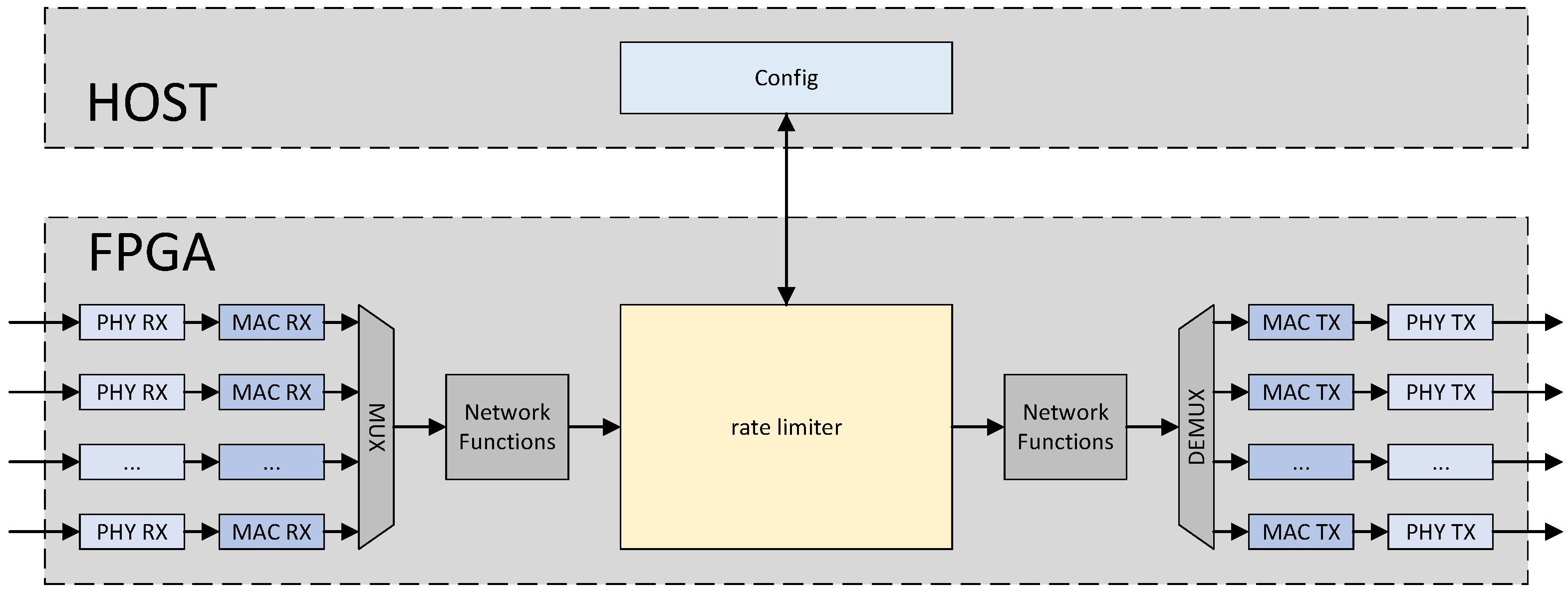
The position of the proposed multi-tenant rate limiter within the system is illustrated in
Figure 1. Similar to most programmable network switches currently in use, packets received from different optical ports are parsed by the physical layer and the media access control (MAC) layer, and then aggregated into a single network flow. Subsequently, the packets are processed by various network functions, including parsing, table lookup, and forwarding. During this process, packets belonging to different flows are tagged with different labels, which are carried in the user-defined signals. Packets with the same label belong to the same queue, and the transmission rate of this queue can be configured on the host server. Subsequently, these packets are buffered in the rate limiter, where packets belonging to the same queue follow the first-in-first-out (FIFO) rule. Under the rate limiting rules, packets that are buffered earlier in the rate limiter are scheduled before those buffered later within the same queue. The scheduled packets then continue through a series of optional network functions and are subsequently forwarded to different optical ports. The host can reconfigure the rate limits for each queue.
The scheduling model mentioned in PIEO [
15] is referenced, where the scheduling algorithm is decoupled from the queues awaiting scheduling. The scheduling algorithm calculates and schedules the head packets of the queues that need to be scheduled. The internal structure of the multi-tenant rate limiter is illustrated in
Figure 2. Packets are first evaluated by the Packet Dispatch to determine whether they should be discarded. If the space occupied by the queue to which the incoming packet belongs in the Shared Packet Buffer exceeds the configured threshold, or if the total space occupied by the Shared Packet Buffer surpasses the threshold, the packet is discarded by the Packet Dispatch. Otherwise, the packet is buffered in the Shared Packet Buffer. Whenever a new packet is buffered in a queue, or when there are still packets remaining in the queue after the head packet has been scheduled, the Shared Packet Buffer sends the queue ID to the Timestamp Calculator. The Timestamp Calculator then computes the next scheduling time for the head packet of this queue. Once the computation is complete, the queue ID and the corresponding time are sent to the scheduler. The scheduler functions as an alarm clock, releasing the queue ID when the current time matches the calculated timestamp and sending it back to the Shared Packet Buffer. Finally, the Shared Packet Buffer retrieves the head packet of the queue from the buffer based on the queue ID. Consequently, the Timestamp Calculator and Scheduler collaboratively constitute the scheduling algorithm, with the queues awaiting scheduling being buffered in the Shared Packet Buffer.
3.1. Shared Packet Buffer
The detailed design of the Shared Packet Buffer has been elaborated in our previous work [
16]. The Shared Packet Buffer is equivalent to a set of FIFOs with configurable depths, where the number of these FIFOs corresponds to the number of queues. These FIFOs share the buffer space of the Shared Packet Buffer. The buffer space is divided into equally sized blocks. Incoming packets are segmented based on their sizes and cached into the corresponding blocks. The Shared Packet Buffer manages the cached blocks of packets using linked lists and also organizes packets arriving at the same queue in the order of their arrival using another linked lists. Additionally, the Shared Packet Buffer sends queues whose head packets’ timestamps need to be calculated to the Timestamp Calculator. Upon receiving the queue ID that needs to be scheduled from the Scheduler, the Shared Packet Buffer reads out the head packet of that queue.
3.2. Timestamp Calculator
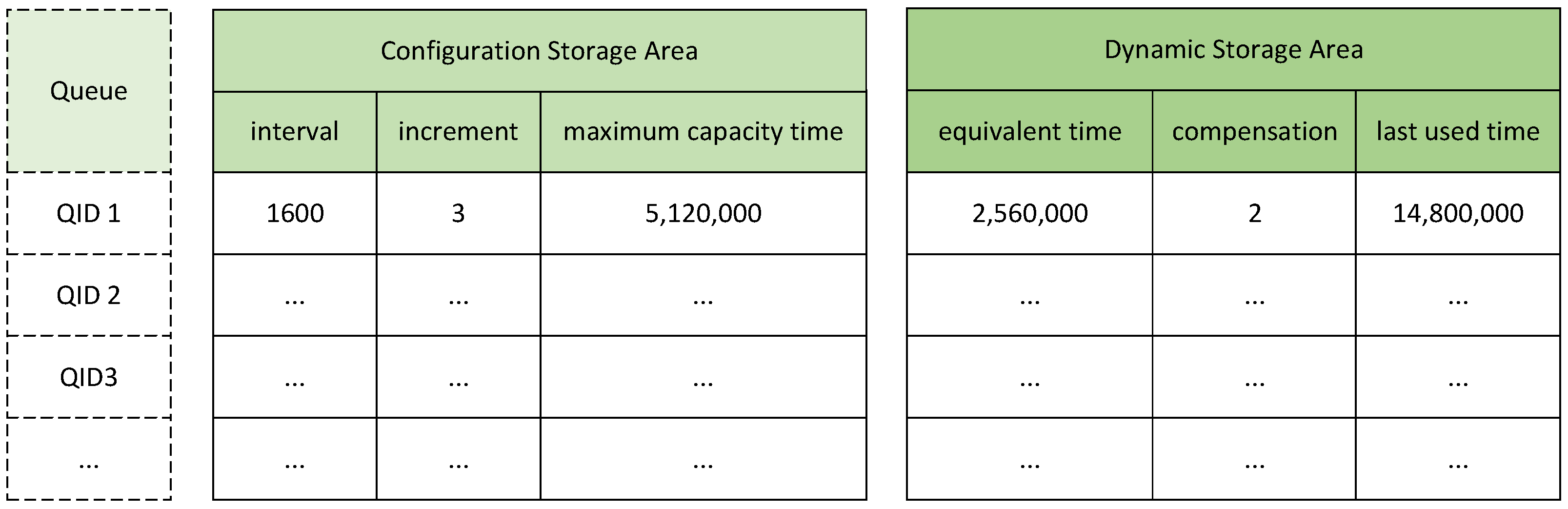
The Timestamp Calculator is utilized to determine the scheduling time for the head packet of each queue. It comprises two main components: a storage part and a computation part. The storage part is further divided into a configuration storage area and a dynamic storage area. The configuration storage area caches parameters that characterize the rate at which a queue acquires tokens and the depth of the token bucket. In contrast, the dynamic storage area is employed to cache the intermediate parameters updated after the last computation for that queue.
As illustrated in
Figure 3, the parameters ITV (interval) and INC (increment) collectively signify that the queue acquires INC (increment) number of tokens within ITV (interval) clock cycles, with each token corresponding to one byte. The depth of the token bucket is reflected by the MCT (maximum capacity time), which denotes the number of clock cycles required for the token bucket to fill from zero to its maximum capacity. Regarding the dynamic storage area, the EQT (equivalent time) represents the equivalent accumulation time of the remaining tokens in the bucket after its last use. Since the calculation of accumulation time is discrete, CPS (compensation) is used to record the number of remaining tokens after each computation of the accumulation time. Additionally, the LT (last used time) records the time of the last use of the token bucket to facilitate the calculation of the number of tokens accumulated during the subsequent period.
As shown in
Figure 3, the ITV (interval) for
QID1 is configured to be 1600, and the INC (increment) is set to 3. Assuming the system operates at a frequency of 200 MHz, then each ITV (interval) corresponds to 5 ns. Therefore,
QID1 can accumulate 3 tokens, equivalent to 24 bits, for every 1600 ITVs (intervals), which denotes a duration of 8000 ns. Consequently, the token accumulation rate for
QID1 is 3 Mbps. The MCT (maximum capacity time) is configured as 5,120,000, indicating that the token bucket corresponding to
QID1 can store a maximum number of tokens that can be accumulated for 5,120,000 ITVs (intervals), which equates to 9600 bytes. The EQT (equivalent time) is set to 2,560,000, signifying that after the last scheduling, the queue has an equivalent of 2,560,000 ITVs’ (intervals’) worth of token accumulation time remaining, corresponding to 4800 tokens in the token bucket. The CPS (compensation) indicates an additional two tokens remaining. Thus the total number of remaining tokens in the bucket is 4802.
When the head packet of a queue requires scheduling time calculation, all parameters cached in both the configuration storage area and the dynamic storage area for that queue are read out. The computation part then calculates the scheduling time based on these parameters. After the computation is completed, the parameters in the dynamic storage area are updated with new values.
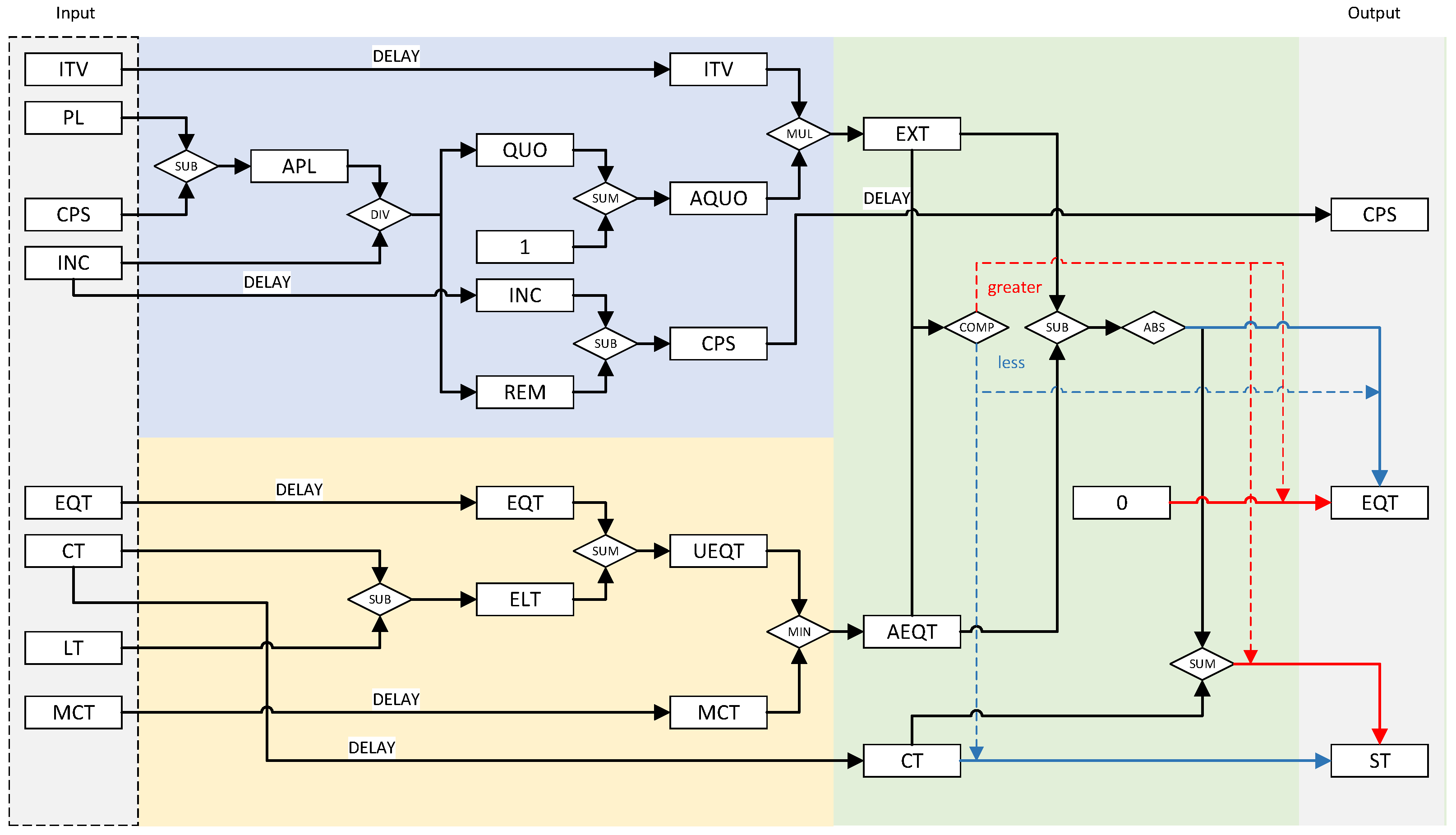
The circuit structure of the computation part is illustrated in
Figure 4. In our design, tokens are replaced by the time taken to accumulate tokens. Whenever a queue requires the scheduling time of its head packet to be calculated, the computation part performs the calculation based on the parameters read from the configuration storage area and dynamic storage area. To calculate the scheduling time of the packet, we should first calculate the time taken to accumulate tokens corresponding to the packet based on the packet length and the corresponding parameters of the token bucket (the blue part in the figure) and the time taken to accumulate tokens accumulated in the token bucket (the yellow part in the figure). Finally, we calculate the time when the packet should be scheduled and update the corresponding parameters of the token bucket (the green part in the figure).
As shown in the blue part of
Figure 4, the EXT (expected time), which represents the number of clock cycles required to accumulate tokens equivalent to the PL (packet length), is first calculated. Initially, the APL (adjusted packet length) is obtained by subtracting the CPS (compensation) from the PL (packet length). Subsequently, the APL (adjusted packet length) is divided by the INC (increment) to yield a QUO (quotient) and an REM (remainder). Immediately thereafter, the AQUO (adjusted quotient) is obtained by adding one to the QUO (quotient), while the updated CPS (compensation) is recalculated by subtracting the REM (remainder) from the INC (increment). Next, the EXT (expected time) is derived by multiplying the AQUO (adjusted quotient) by the ITV (interval). The CPS (compensation) indicates the number of additional tokens accumulated in the token bucket during the EXT (expected time), beyond those corresponding to the PL (packet length). Since the token accumulation process is discrete, the calculated EXT (expected time) is always a multiple of the ITV (interval). Therefore, it is necessary to use the CPS (compensation) to adjust for the overestimation.
While calculating EXT (expected time) and CPS (compensation), as shown in the yellow part of
Figure 4, the AEQT (adjusted equivalent time), which signifies the accumulated time associated with the tokens in the bucket from the last token bucket usage until the current time, is computed based on EQT (equivalent time), LT (last used time), and the CT (current time). By subtracting the LT (last used time) from the CT (current time), the ELT (elapsed time) is calculated. Adding ELT (elapsed time) to EQT (equivalent time), the resulting value, quoted as UEQT (updated equivalent time), is compared to the MCT (maximum capacity time) read from the configuration storage area. The minimum of these two values represents the AEQT (adjusted equivalent time).
Finally, as shown in the green part of
Figure 4, the scheduling time of the head packet of the queue is calculated. The AEQT (adjusted equivalent time) and the EXT (expected time) are compared. If the AEQT (adjusted equivalent time) is greater than the EXT (expected time), it indicates that there are sufficient tokens for scheduling the packet, and the packet should be scheduled immediately. Therefore, the ST (scheduling time) is equal to the CT (current time). Conversely, if the AEQT (adjusted equivalent time) is less than the EXT (expected time), it indicates that there are not enough tokens for scheduling the packet, and the packet should be scheduled when the tokens are accumulated sufficiently. Thus, the difference obtained by subtracting the AEQT (adjusted equivalent time) from the EXT (expected time) is added to the CT (current time) to obtain the ST (scheduling time).
Also as shown in the green part of
Figure 4, during the computation of the ST (scheduling time), the EQT (equivalent time) and the CPS (compensation) are updated back to the dynamic storage area. When updating the EQT (equivalent time), the EXT (expected time) is subtracted from the AEQT (adjusted equivalent time). If the AEQT (adjusted equivalent time) is less than the EXT (expected time), the EQT (equivalent time) is updated as zero.
3.3. Scheduler
The Scheduler determines when to release a queue ID and schedule the head packet of that queue. It consists of a PIFO [
17] and a timer. PIFO is a programmable scheduling model that allows elements to be inserted into a queue at arbitrary positions based on their priority, while only dequeuing from the head of the queue. Unlike traditional PIFO structures, our Scheduler’s PIFO introduces a constraint on the dequeue operation based on the value of the timer. Only when the value of the head element is not greater than the value of the timer will the head element be dequeued.
As shown in
Figure 5, ST denotes the scheduling times that have been calculated for different queues. PIFO has already arranged
ST1 and
ST2 in ascending order. The calculation of
ST3 has been just completed. Given that
ST3 is greater than
ST1 but smaller than
ST2,
ST3 is subsequently pushed between
ST1 and
ST2. As the value of Timer increases, when the value of Timer becomes greater than or equal to
ST1,
ST1 is dequeued. Subsequently,
ST3 and
ST2 are dequeued in the original order.
The Timer is driven by the system clock and starts counting when the system boots up. The Timer also serves as the current time reference for the tag computation circuit to calculate scheduling times.
4. Implementation and Evaluation
To facilitate implementation on an FPGA, we conducted our development within the Corundum [
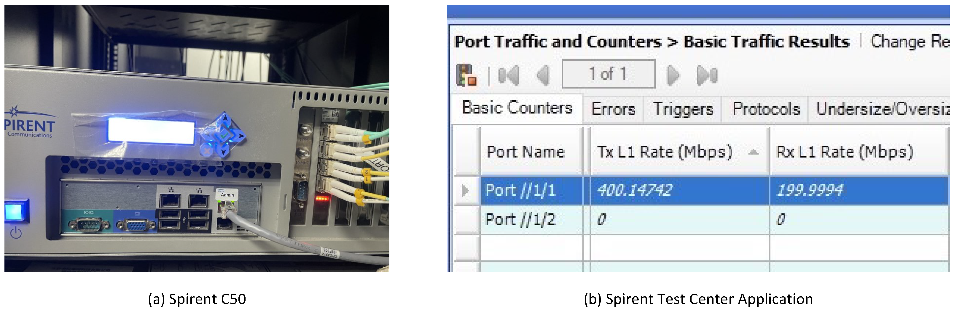
18] development framework. Modifications were made to the original framework to enable packets entering the FPGA through one port to be directly forwarded to another port. Concurrently, a rate limiter was integrated into the packet processing pipeline, and parameters for different queues were configured via read–write operations on registers. The proposed multi-tenant rate limiter was developed using Verilog. During the development process, ModelSim SE-64 2020.4 (Mentor Graphics (now part of Siemens, in Munich, Germany)) was employed for simulation. Vivado 2020.2 was utilized for synthesis and to generate the final bitstream file. The proposed multi-tenant rate limiter was evaluated using a Xilinx Kintex-7 series xc7k325tffg900-2L FPGA (Sugon, Beijing, China) deployed on a Dell R740 server (Dell, Beijing, China). During the evaluation, each port of the FPGA was connected to a Spirent C50 (Spirent Communications plc, Crawley, West Sussex, UK) via an optical fiber. As shown in
Figure 6, Spirent C50 is the traffic generator and the device employed to measure rate limiting. The resource utilization and rate limiting accuracy were assessed.
4.1. Scheduling Capacity
The implemented multi-tenant rate limiter supports up to 512 rate limiting queues. All components operate at a frequency of 200 MHz. However, for a single queue, there is a minimum delay of 12 clock cycles from the start of calculating the scheduling time of the head packet to the packet being scheduled out. Additionally, there is a further delay of seven clock cycles from the head packet being scheduled out to the queue ID being pushed back into the scheduler. Therefore, the maximum scheduling capacity for a single rate limiting queue is 10.53 Mpps.
The scheduling of different queues is independent, and the scheduling delay of one queue mentioned above does not affect the scheduling of another queue. All of the queues use the same Timestamp Calculator circuit to calculate scheduling time of their head packet. The bottleneck in scheduling capacity lies in the chosen FPGA device, which is equipped with only four 10 Gbps SFP+ optical modules. Moreover, the data width of the AXI-Stream bus is set to 128 bits, thereby restricting the throughput of the Shared Packet Buffer for packet writes and reads to 25.6 Gbps. As shown in
Figure 7, the simulation results of the Timestamp Calculator and Scheduler indicate that the total scheduling capacity for all queues can reach 200 Mpps because the token ID can be input into the Timestamp Calculator for every clock period and the Scheduler can schedule the head packet of the corresponding queue in every clock period. This level of performance is expected to be achievable if the proposed multi-tenant rate limiter is implemented on a more advanced FPGA card.
4.2. Power Consumption
The implemented multi-tenant rate limiter incurs an additional power consumption of 11.639 W. Specifically, the signal portion accounts for 5.243 W, the logic portion consumes 6.187 W, the BRAM occupies 0.195 W, and the DSP, along with other components, accounts for 0.014 W. Given its power consumption profile, the implemented multi-tenant rate limiter is lightweight and imposes virtually no additional burden on heat dissipation and power supply requirements.
4.3. Hardware Resource Evaluation
The resource utilization of the tag computation module is shown in
Table 1 and compared with the work of Benacer et al. [
11]. When the number of supported queues increases from 64 to 512, the resource consumption of the tag computation module remains almost unchanged. This is because all parameters and variables related to the queues are cached in BRAM, and the minimum configurable address count of BRAM on the selected FPGA board is 512. This means that when the number of supported queues is not greater than 512, the tag computation module always occupies 2.5 BRAM blocks. The resource utilization for supporting 1024 and 2048 queues is also presented in the table. When the number of supported queues exceeds 512, the number of occupied BRAMs varies linearly with the number of queues. However, the original design intention of our work was not to occupy a large number of BRAMs, which may be utilized for other network functions such as lookup tables and packet buffering. Therefore, the linear increase in BRAM occupancy with the number of supported queues represents a potential bottleneck when discussing larger-scale systems.
When the number of supported queues increases, the occupied logic resources will increase slightly. This is because some intermediate variables need to be appropriately delayed during the tag computation to wait for other intermediate variables that participate in the same computation to be calculated. The corresponding queue IDs also need to be delayed simultaneously to mark and distinguish different intermediate variables. The bit width of the queue ID changes according to the number of supported queues, which leads to minor variations in logic resource utilization.
The variations in resource consumption of the tag computation module when supporting different numbers of queues indicate that our work has an advantage in terms of scalability. In contrast, Benacer et al.’s work exhibits a linear increase in logic resource utilization with the number of supported queues because only flip flops and LUTs are used to obtain a pipelined and fast architecture in the proposed traffic manager, and BRAMs are only used in the Flow Management Table module. Our work consumes only 1.16% of the LUTs and 2.62% of the FFs consumed in Benacer et al.’s work when supporting 512 queues. Specifically, when the number of supported queues doubles, the occupied logic resources of the comparative work approximately double as well. When supporting a smaller number of queues, such as 64, the consumed LUTs account for approximately 11% of the xc7z045ffg900-2 FPGA. This level of resource consumption is acceptable because it leaves sufficient resources for the development of other functionalities. However, when the number of supported queues increases to 512, Benacer et al.’s work consumes about 86% of the LUTs. This high resource utilization rate leaves minimal logic resources available for other functionalities and also restricts the operating frequency. In fact, when supporting 512 queues, Benacer et al.’s work can only operate at 93 MHz. In contrast, our tag computation module can consistently operate at 200 MHz, regardless of the number of supported queues.
4.4. Precision of Rate Limiter
The precision of the rate limiting mechanism is evaluated using a single-queue configuration. During the testing process, a traffic generator is employed to generate packets, all being mapped to the same queue. The packet lengths generated by the traffic generator vary randomly between 256 bytes and 1500 bytes. Different rate limiting configurations are applied to the queue, while ensuring that the packet transmission rate of the traffic generator is significantly higher than the configured limiting rate of the queue. In the test, the configured limiting rates are divided into five groups, as shown in
Table 2. The packet receiving rates from another port are recorded and compared with the configured limiting rates. The results obtained are also illustrated.
The configured rate limiting values in different groups fall within distinct ranges. In the range from 1 Mbps to 10 Gbps, all the queues have configured rate limiting values with three significant figures. This indicates that our work supports an extremely high configuration precision ranging from 1 Mbps to 10 Gbps. Our work supports a configuration precision of 10 Kbps even within the range of 100 Kbps to 1 Mbps. In terms of the precision of rate limiting implementation, the deviations in most experimental results are within 0.1%, and all rate limiting results have deviations within 0.4%. Considering the short-term fluctuations in rate limiting caused by variations in packet length when the configured rate limiting values are low, these results demonstrate that our work supports highly precise single-queue rate limiting.
Regarding the evaluation of the precision of rate limiting across multiple queues, four queues were selected for the rate limiting test. The traffic generator simultaneously sends four distinct streams of packets, which are mapped to four separate queues before entering the multi-tenant rate limiter. Rate limiting is configured for these four queues, ensuring that the packet input rate to the multi-tenant rate limiter for each queue is significantly higher than the configured rate limiting value. The test was divided into three groups. In the first group of experiments, all queues were configured with relatively small rate limiting values to assess the precision of our proposed multi-tenant rate limiter. In the second group of experiments, all four queues were configured with relatively large rate limiting values. In the third group of experiments, two queues were configured with large rate limiting values, while the other two queues were configured with small rate limiting values. The results of the tests are shown in
Table 3.
The experimental results show that when the rate limiting values are all small, the maximum rate limiting bias is 1.213‰, and when the rate limiting values are all large, the rate limiting bias will not exceed 0.18‰. When multiple queues are rate limited at the same time, but some queues are configured with small rate limiting values and some queues are configured with large rate limiting values, the maximum rate limiting bias is 2.02‰. In the above scenario, when the rate limiting values configured for multi-queues differ too much, methods like that in [
6] cannot achieve good accuracy. However, our method still supports high-precision rate limits when limiting different queues. Thus, the experimental results demonstrate that our work supports high-precision rate limiting across multiple queues in various scenarios.
4.5. Security and Reliability
Packets from 512 queues were sent by the traffic generator, with each queue transmitting at a rate of 15 Mbps. The rate limit for each queue was set to 10 Mbps to conduct a heavy load test. The traffic was continuously generated for one hour, during which the rates of packets received at another port of the traffic generator were monitored. The experimental results indicate that, after one hour of continuous traffic rate limiting, our proposed work still maintains high reliability and accuracy. To enhance the fault tolerance of our work, the Timer’s clock bit-width was set to 64 bits. Calculated based on the operating clock of 200 MHz, our multi-tenant rate limiter is theoretically capable of continuous operation for approximately 2900 years.


