Article

Fault-Tolerant Control of a Multiphase Series Capacitor Buck Converter in a Master–Slave Configuration for Powering a Particle Accelerator Electromagnet

by
Edorta Ibarra
1,*,
Antoni Arias
2,
Iñigo Martínez de Alegría
1,
Alberto Otero-Olavarrieta
3,
Asier Matallana
1 and
Louis de Mallac
4
1
Department of Electronics Technology, University of the Basque Country (UPV/EHU), 48013 Bilbao, Spain
2
Electronic Engineering Departament, Universitat Politècnica de Catalunya, BarcelonaTech (UPC), 08028 Barcelona, Spain
3
Electrical Engineering Department, Universidad de la Rioja (UR), 26006 Logroño, Spain
4
Electrical Power Converters Group, Accelerator Systems Department (SY), The European Organization for Nuclear Research (CERN), 1211 Geneva, Switzerland
*
Author to whom correspondence should be addressed.
Electronics 2025, 14(5), 924; https://doi.org/10.3390/electronics14050924
Submission received: 30 December 2024 / Revised: 10 February 2025 / Accepted: 17 February 2025 / Published: 26 February 2025

Abstract

:
Multiphase DC/DC power converter architectures have recently been investigated for powering the superconducting electromagnets in the High-Luminosity (HL) upgrade of the Large Hadron Collider (LHC) at CERN, targeting high-performance figures and reliability. In terms of control, a master–slave voltage/current regulation configuration was previously proposed by the authors as an alternative to other well-known cascaded options. In this work, fault-tolerant features (i.e., diagnosis and reconfiguration under open-circuit switch faults) are incorporated into the aforementioned proposal. These features are highly desirable, as physics experiments—which can last for several hours—should not be interrupted in the event of a recoverable fault in the powering system. Simulation and experimental results are provided, demonstrating the correctness of the proposed fault-tolerant scheme.

1. Introduction

High-precision switched power converters play an important role in the powering of superconducting electromagnets in modern particle accelerator systems [1,2,3,4,5,6,7,8]. Two-staged warm powering solutions based on a multiphase output DC/DC power converter have recently been investigated in the context of the High-Luminosity (HL) upgrade of the Large Hadron Collider (LHC) at CERN [1,3,4]. The two-staged approach provides the following benefits over existing solutions [1,3]:
(a)
The load is decoupled from the power grid through the incorporation of an intermediate low-voltage (24 V) battery pack. In this way, it is possible to independently dimension the upstream and downstream parts of the converters. In addition, a better ride-through capability is obtained.
(b)
The battery pack enables the recovery of part of the magnet’s energy.
(c)
Interleaved pulse width modulation (PWM) reduces the output voltage and current ripples. This helps the system to reach the stringent ppm requirements set for the output current ripple.
(d)
Its modularity and the incorporation of redundant DC/DC units make maintenance easier.
Regarding this last point, in the event of a failure and once the system is stopped, the modular approach allows users to rapidly change the DC/DC phases and repair the power converter. Substituting a module requires human intervention. It must be borne in mind that, in particle accelerator facilities, high radiation levels may be present during and after experiments [9]. This makes the use of on-line fault-tolerant control and diagnosis solutions a highly desirable option. In addition, the long-plateau operating profiles of the electromagnets that need to be tracked during experiments, which can last several hours (refer to [3] for more detail), can be obtained without stopping the system if fault tolerance is provided, minimizing power-down times.
Power switch-related faults are the most common failure mechanisms in DC/DC converters [10,11]. A comprehensive study was carried out in [11], focusing on series-resonant (SRC) and LLC converters. The study pointed out that 57.1% of failures occur within the semiconductors themselves or their firing circuitry due to over-currents (reduced load impedance, converter control errors, faulty driver pulses, and human errors when mounting), over-voltages (supply voltage errors in the driver circuitry, emitter/source d i / d t feedback, gate over-voltages, parasitic oscillations, etc.), or over-temperatures (excessive currents, problems with thermal management elements, etc.). The conclusions of this analysis could be extrapolated to other high-power DC/DC systems, such as those used for the powering of superconducting electromagnets.
As a consequence of the aforementioned failure mechanisms, power switches can remain permanently latched in open or short circuits. The latter creates the most serious hazard, as the failure can quickly propagate to other converter elements. Many gate-driver solutions provide ultra-fast short-circuit fault identification [12,13], which can be used to isolate the fault. The incorporation of passive protections such as fast-acting fuses could also be used to clear the fault and leave the broken element in an open circuit [14]. For these reasons, open-circuit fault detection, diagnosis, and fault-tolerant control solutions have attracted the interest of many authors within the power electronics community [15,16,17,18,19].
From a hardware perspective, multiphase DC/DC systems, such as those being investigated for the powering of the HL-LHC superconducting quadrupole electromagnets, are inherently fault tolerant to open-circuit faults; hence, no hardware reconfiguration is needed when an open-circuit fault occurs. However, control and diagnosis algorithms need to be developed.
This work focuses on the first-quadrant operation ( v o u t > 0 and i o u t > 0 ) of the multiphase converter solution proposed by the authors in [3] for powering superconducting electromagnets. This converter is based on the parallelization of series capacitor (SC) buck [20,21,22] sub-converters. Its second-quadrant operation ( v o u t < 0 and i o u t > 0 ) is not considered within this work. Novel fault diagnosis and post-fault controller reconfiguration solutions, which avoid the incorporation of any extra hardware elements, are proposed here. These solutions are implemented in an FPGA, which is already controlling a power converter prototype. Thus, all the proposals are fully digital and do not increase the cost of the power conversion system.
This article is organized as follows: Section 2 provides an overview of the operational requirements of the developed DC/DC powering stage. Section 3 provides a brief description of the impact of open-circuit faults on SC buck converters, and analogous results for conventional single-switch buck configurations are deduced. In Section 4, various multiphase DC/DC control structures are analyzed, and their fault-tolerant requirements are introduced. Then, both the novel fault detection and fault-tolerant control algorithms are presented and described in Section 5. Simulation results are included to exemplify their operational principles and performance. Section 6 demonstrates the feasibility of the proposed algorithms. For this purpose, experimental tests are carried out in a full-scale four-phase SC buck power supply prototype. The main conclusions are summarized in Section 7.

2. Operational Requirements of the IT Magnet Powering Application

The IT magnet’s slow-ramped powering process comprises three differentiated operational phases [23]. First, a positive voltage is applied to the load, resulting in a ramp-up phase where the magnet’s current ( i m a g ) slowly increases at a rate of 16 A/s, until i m a g = 16230 A. This high current is achieved by the parallelization of multiple DC/DC converters. Once the steady-state condition is reached, i m a g is maintained at the aforementioned value. This flat-top phase typically lasts 10 h, where physical experiments are carried out. Finally, i m a g is slowly ramped down until the energy stored within the IT magnet is recovered to the batteries. Thus, the DC/DC output voltage regulation has slow dynamic requirements.
The maximum voltage to be applied to the electromagnet will depend on the value of the resistance R w , which is introduced by the copper connection between the power electronics and the magnesium dibore ( M g B 2 ) superconducting link [24]. In buck mode, output voltages of up to 10 V are considered for emergency situations, while values of 4 V (or less) are expected during normal operation.
Table 1 summarizes the most relevant operating parameters of the single converter unit considered in this work, constituted by four SC buck sub-converters, which would be parallelized for the final application.

3. The Effects of Open-Switch Faults in DC/DC Buck Sub-Converters

3.1. Conventional Buck Configuration

Figure 1a shows the most common architecture for a single-switch buck sub-converter. Note that, in this particular case, a passive output damping net ( R d and C d elements) is included to improve the poor damping factor that results when connecting the converter to an almost purely inductive load [3].
Here, it becomes clear that if MOSFET M fails in an open circuit, this is equivalent to applying a duty cycle of δ = 0 . Consequently, i j = 0 . In a multiphase configuration, the remaining sub-converters should share the current (power) that was previously circulating through the now faulty unit.

3.2. Series Capacitor Buck Configuration

Figure 1b shows a single sub-converter of the SC buck solution. Its utilization was proposed in [3] as an alternative to the conventional buck for quadrupole electromagnet powering because it provides better performance under a high step-down ratio operation, which is common for the application. In addition, the amount of current sensors (and current balancing control loops) required is halved for the same number of interleaved switches, reducing the system’s complexity.
In a healthy operation, M 1 and M 2 receive pulses from the same duty cycle command δ , but the firing signals are interleaved at 50% during the modulation period T s w . As a result, currents i L a and i L b are naturally balanced when δ < 0.5 . Following the small ripple approximation, the voltage in SC is v s c = 0.5 v d c . If, for some reason, M 1 remains permanently open, v s c does not charge and eventually discharges ( v s c = 0 ). Thus, i j = 0 regardless of whether M 2 is healthy or not. If M 2 is the one failing in an open circuit, and M 1 is healthy, the SC and dc-link voltages become equalized in a steady state ( v s c = v d c ). As a result, no current flows from the battery to the load, and again, i j = 0 . Thus, the behavior of the SC buck is equivalent to the conventional buck when any of its controllable switches remains permanently open due to a fault.

4. Voltage and Current Regulation Approaches for Interleaved Multiphase DC/DC Converters

In parallel-connected interleaved buck DC/DC converters, the output voltage needs to be precisely regulated while keeping the currents of all the sub-converters balanced [25]. This is mandatory for high-current applications, where relevant current differences could produce thermal unbalances within components and jeopardize the safety of the system.
In general, two control approximations could be classified: those based on a cascaded set-up and those based on a master–slave configuration.

4.1. Cascaded Closed-Loop Control Approaches

Regulation approaches with cascaded voltage and current closed-loop controllers are the most popular for regulating interleaved DC/DC converters [25]. Here, the external loop (voltage) dynamics need to be set, at least with a settling time ten times slower than the ones of the inner loops (current). A variety of configurations can be implemented, for example, the ones depicted in Figure 2, where current sensing per each sub-converter is mandatory.
PI-based voltage and current regulators [25] are among the most commonly used in these cascaded configurations. However, other approaches such as the ones based on sliding mode control (SMC) theory (PI-based voltage controller complemented with SMC-based current controllers) can also be found in the literature [26,27].
From a closed-loop controller perspective, these approaches are inherently fault tolerant against open-circuit faults. When one of the sub-modules fails, the remaining ones share the additional current, as set-point i j * = i o u t / N (Figure 2) automatically increases to i o u t / ( N 1 ) , where N indicates the number of phases in the system.
In principle, the intrinsic fault tolerance of these cascaded configurations does not require any specific fault detection and diagnosis technique. However, if the system must continue taking full advantage of the interleaving PWM (as it should for the case of powering the final focusing quadrupole magnets of the HL-LHC upgrade due to the tight constraints on the output current ripple at the sub ppm level), the pulses should be reconfigured accordingly [16,28,29]. This makes identification of the faulty unit(s) necessary.

4.2. Master–Slave Closed-Loop Control Approach

Alternatively, a master–slave control configuration was proposed by the authors in [3] to regulate a multiphase DC/DC buck prototype (Figure 3) to power the final focusing magnets for the HL-LHC upgrade.
When all the elements of the multiphase power system are considered, including the output side passive damping nets, a multiple-input multiple-output (MIMO) system is obtained when mathematically setting the relationship between the T s w averaged sub-converter control actions v 1 , v 2 ,… v N and magnitudes v o u t , i 2 ,… i N [3]:
v o u t i o u t , 2 i o u t , 3 i o u t , N = F 1 ( s ) F 1 ( s ) F 1 ( s ) F 1 ( s ) F 2 ( s ) F 3 ( s ) F 2 ( s ) F 2 ( s ) F 2 ( s ) F 3 ( s ) F 2 ( s ) F 2 ( s ) F 2 ( s ) F 2 ( s ) F 3 ( s ) v 1 v 2 v 3 v N ,
where
F 1 ( s ) = α ( s ) s L + α ( s ) = 1 / N L C s 2 + ( L / R ) s + 1 ,
F 2 ( s ) = α ( s ) s L s L + α ( s ) = 1 / N L 2 C s 3 + ( L 2 / R ) s 2 + L s ,
F 3 ( s ) = 1 s L + α ( s ) = L C s 2 + ( L / R ) s + ( N 1 ) / N L 2 C s 3 + ( L 2 / R ) s + L s ,
and R = N R d , L ( L = L a | | L b in SC configuration), and C = C o u t / N are the equivalent resistances, inductances, and capacitances of the system, respectively.
As demonstrated in [3], it is possible to find a decoupling matrix that allows a fully decoupled control of v o u t , i 2 ,… i N through control actions v 1 , … v N (see Figure 3):
T = 1 ( N 1 ) F 2 ( s ) F 2 ( s ) F 3 ( s ) 1 1 F 2 ( s ) F 2 ( s ) F 3 ( s ) 1 0 0 F 2 ( s ) F 2 ( s ) F 3 ( s ) 0 0 1 .
In the resulting control structure of Figure 3, voltage and current regulators can be designed and adjusted in the z-domain using well-known single-input single-output (SISO) tools. Therefore, the master voltage and slave current controllers can be tuned with precise dynamics, namely, the settling time T s , % and damping factor ξ . The authors refer the readers to [3] for detailed information on the design and tuning of the voltage and current controllers.
The proposed controller requires measuring the output currents of all the SC buck cells, for example, placing Hall-effect sensors after the interconnection points of the cells’ inductors L a and L b (Figure 1b). The currents measured from the slave cells ( i 2 to i N ) provide feedback to the current controller units (Figure 3). In contrast, the measured current of the voltage-regulated sub-converter ( i 1 ) sets the reference currents i 2 * to i N * , which are then provided to all the current controllers (Figure 3). In this way, the slave cell currents follow i 1 , and all the modules become balanced.
As experimentally demonstrated in [3], very good dynamic performance is achieved, even with a considerable amount of parameter mismatches between the theoretical model and the physical system, proving the correctness of the proposal.
In contrast to the closed-loop approaches explained in Section 4.1, the master–slave structure shown in Figure 3 does not provide intrinsic fault tolerance, and control reconfiguration is mandatory. To achieve this, the origin of the fault needs to be identified first. In the next section, the proposed fault-tolerant solution, based on the master–slave control approach, is presented together with a novel fault detection algorithm for interleaved DC/DC converters.

5. Proposed Fault-Tolerant Solution

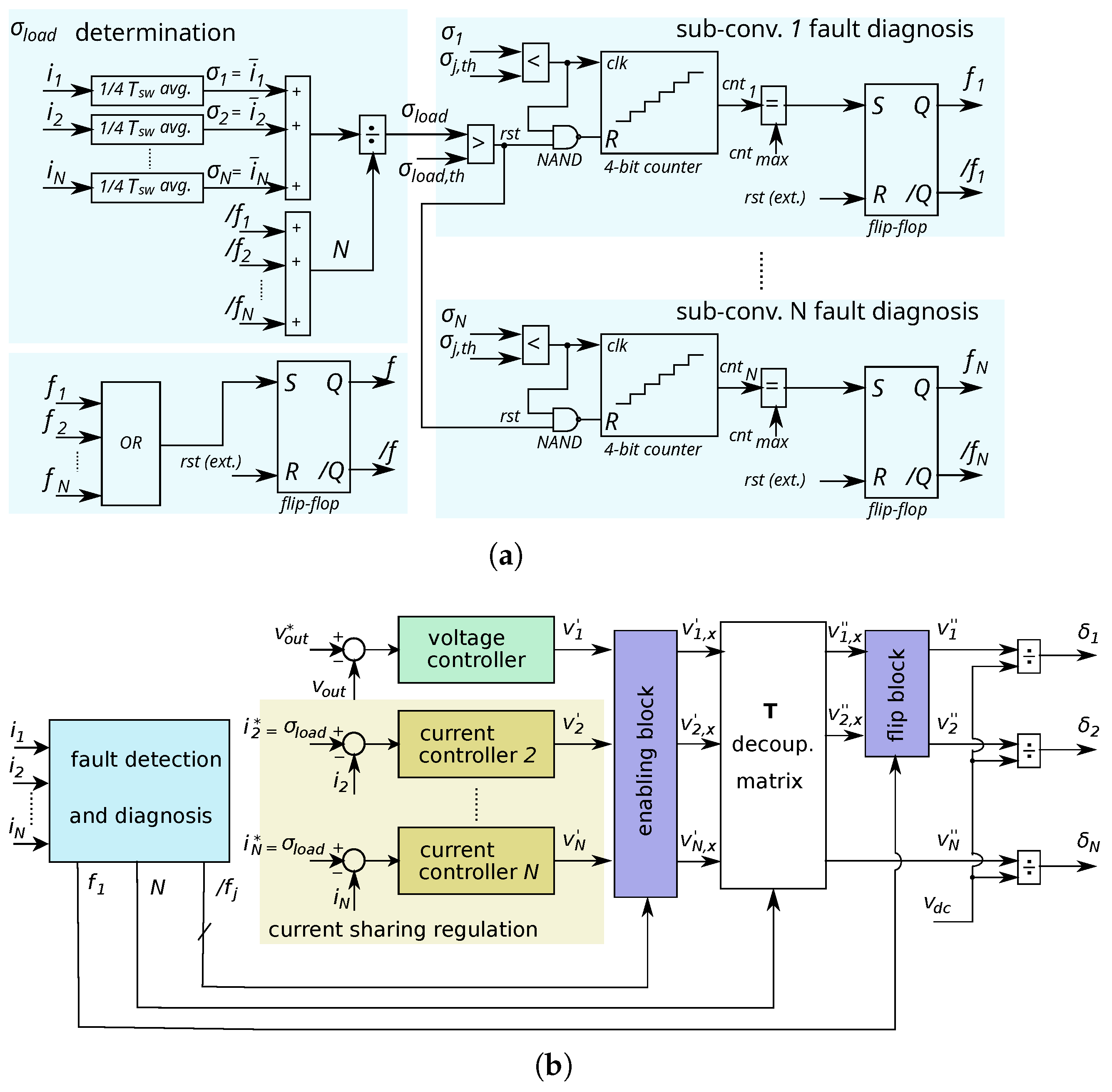
5.1. Open-Circuit Fault Detection and Diagnosis Algorithm Based on the per Sub-Converter Current Analysis

The proposed open-switch fault detection and diagnosis algorithm (Figure 4a,b, light-blue painted blocks) is based on a signal processing analysis in the time domain. It is developed to detect one or more faulty sub-converter units while using the available hardware resources of the power system. Many of the diagnosis algorithms proposed in the literature for DC/DC converters provide ultra-fast detection capabilities (within one or only few T s w ), but they require additional hardware and are based on analog circuitry [16]. Here, a fully digital solution is proposed, making use of the available FPGA, Hall-effect current sensors (one per sub-converter), and 16-bit/1 Msps analog-to-digital (A/D) converters.
The algorithm borrows ideas from well-known current-based techniques, proposed for voltage source inverters [30,31]; however, in this case, the analysis of DC signals is easier than that of three-phase AC signals. The proposed closed-loop controller and PWM blocks are computed once at each T s w period. As the algorithms have been implemented in an FPGA, it is possible to take advantage of the fast computational capabilities available. By oversampling each measured SC output current at each T s w / 4 and applying a moving average filter for each modulation period T s w , the averaged current values i ¯ j are obtained and provided to the closed-loop controller at each k-th sampling instant (Figure 5):
i ¯ j ( k ) = i j ( k ) + i j ( k 1 ) 2 .
The slow dynamics of the IT magnet powering permits utilizing windows with relatively long time frames for the analysis of fault indicators, minimizing the chances of triggering a false-positive alarm flag f j . An overall load indicator σ l o a d is defined first and computed:
σ l o a d ( k ) = 1 N j = 1 N i ¯ j ( k ) .
This indicator is used to determine whether the multiphase system is operating above a given threshold level σ l o a d , t h , which ensures that the per sub-converter current levels are sufficient for reliable detection. Then, the per sub-converter fault indicators are defined as σ j ( k ) = i ¯ j ( k ) . At each sampling time, if σ j ( k ) < σ j , t h , a counter c n t j is incremented. To avoid false positives induced by measurement uncertainties, c n t is cleared when conditions σ j ( k ) > σ j , t h or σ l o a d < σ l o a d , t h are met (NAND gates of Figure 4). When c n t j reaches c n t m a x (number of consecutive faults detected to assess the fault), the fault flag f j is set.
The computing capabilities of an FPGA allows monitoring the status of all sub-converters in parallel. A general alarm flag is finally set as f = f 1 f 2 f N . All these flags are then registered in user-resettable bistables. A compromise between the detection speed and false-positive rejection needs to be found when tuning the parameters c n t m a x , σ l o a d , t h , and σ j , t h .

5.2. Post-Fault Controller Reconfiguration

Figure 4b shows how the post-fault controller reconfiguration is carried out when the master–slave control approach is used. When sub-converter j is in a faulty state, its voltage or current controller cannot cancel the corresponding error. As a result, the control action v j increases. This signal propagates through the decoupling matrix T and perturbs all v j control actions. Thus, the faulty unit needs to be isolated from the controller through the Figure 4 enabling block, where
v x = [ / f 1 , / f 2 , , / f N ] · v ,
and / f j , j { 1 , 2 , N } are the inverted signals of flags f j .
The aforementioned step is enough when the faulty unit is a current-regulated slave module. However, when the failing sub-converter is the master module, another sub-converter, for example, unit 2, needs to take the master role. This can be achieved by setting the control action v 1 = 0 and setting v 2 = v 1 , x (Figure 4). Extending this procedure, subsequent faults within sub-converters acting with a master role can be attended to and fixed.
At a purely mathematical conceptual level, the aforementioned reconfiguration procedures eliminate and rearrange the rows and columns of matrix T , represented in (5), in response to the detected fault(s). Finally, and once the closed-loop controller is reconfigured, the interleaved PWM pulses need to be set accordingly.
It is important to mention that, if the master sub-converter fails, the regulation scheme of Figure 3 fails if i j * = i 1 , as now i 1 = 0 . This critical problem can be solved by commanding the current-regulated units with the load indicator σ l o a d , which represents the averaged per-unit current.

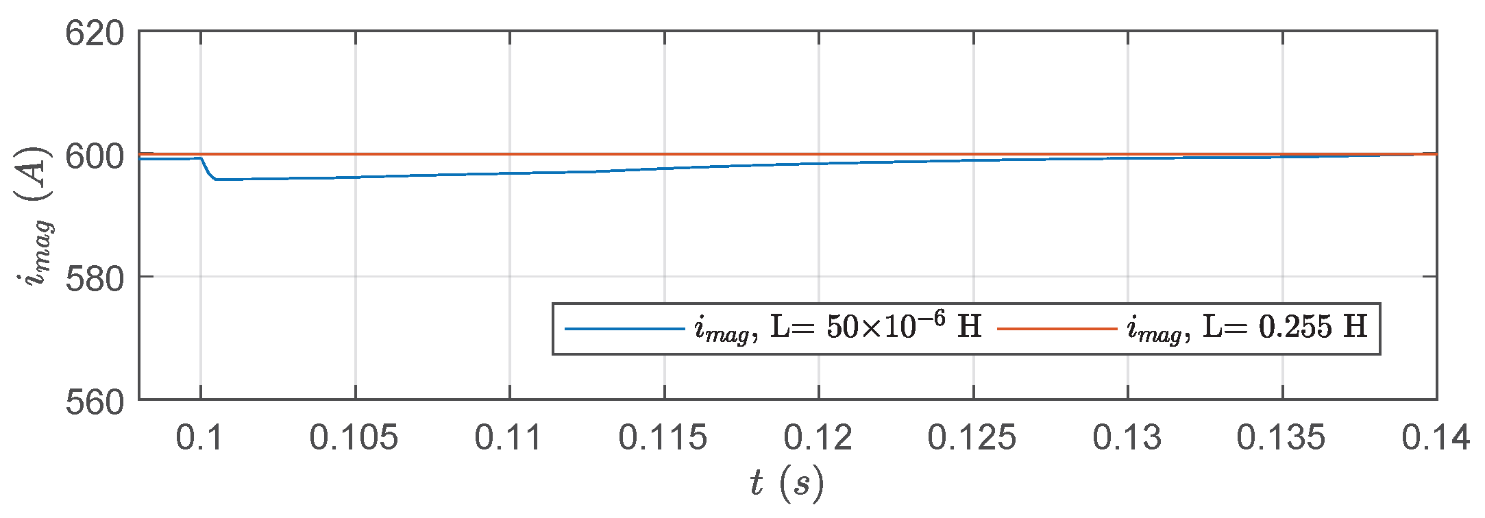
5.3. Dynamics and Stability Considerations of the Controller Under Post-Fault Operating Conditions

Under a healthy operation, once the decoupling matrix in (5) is applied, the master and slaves behave as SISO systems. As described by the authors in [3], the closed-loop poles of the master and slaves can be placed inside the unity circle in the z-domain, providing stable operation and guaranteeing the settling-time specifications.
When a fault occurs in one of the slave sub-modules, the corresponding columns and rows are removed from matrix T without affecting the remaining sub-modules. Thus, the same stability criteria are retained as in a healthy mode. When a fault occurs in the master sub-module, a slave sub-module takes the role of the master. Again, the same stability criteria hold. This is consistent with the simulation and experimental results obtained under faulty conditions with control reconfiguration (Section 5.4 and Section 6.3), as not only is the stability retained but the closed-loop specifications are also maintained.

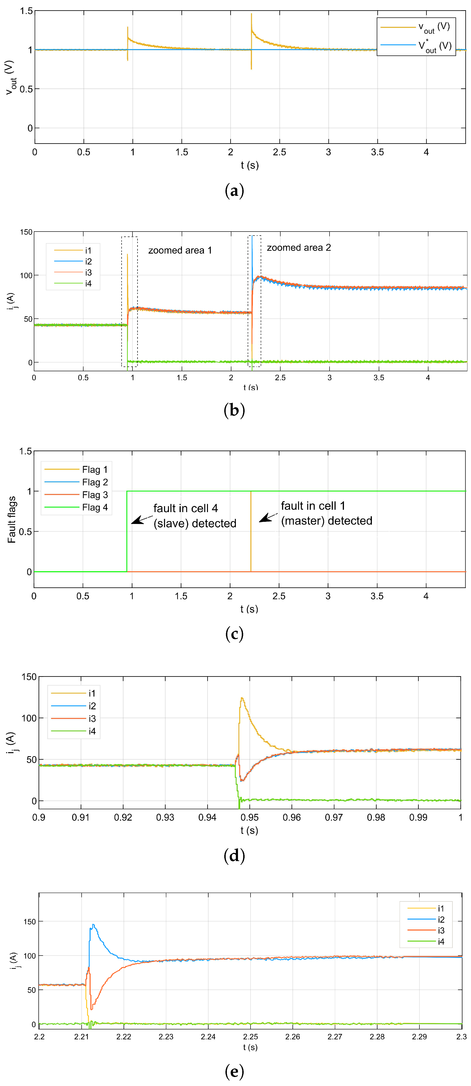
5.4. Simulation Results

Prior to experimentation, the fault-tolerant algorithms are validated by means of simulation. A four SC sub-converter configuration is modeled in Matlab/Simulink, whose layout is depicted in Figure 6. Table 2 presents the most relevant parameters of the model, which corresponds to the experimental set-up available in the laboratory.
Two fault scenarios are studied; that is, when an open-circuit fault occurs within one of the current-regulated sub-converters, herein named slave cells, and when it occurs in the voltage-regulated one, herein named the master cell. The latter fault condition is illustrated in Figure 7, as it represents a more severe control situation (until reconfiguration, v o u t regulation capabilities are missing). An open-circuit fault is induced in switch M 1 of the master cell, at t = 0.1 s, when v o u t * = 3 V. As a result, i 1 quickly becomes zero, as v s c is discharged. The currents of the healthy phases remain balanced due to the control action (Figure 8b). As expected, initially the output voltage does not track the reference (Figure 8a). However, considering the slow electromagnets’ powering dynamics, the fault detection and diagnosis algorithm quickly identify the faulty sub-converter (Figure 8c), and the closed-loop controller and the PWM module phase shifts are reconfigured on the fly. After a brief transient, the system’s performance is recovered, and it continues to operate in a sub-optimal manner. Figure 8 shows that almost equivalent fault detection, diagnosis, and post-fault operation results are obtained when the fault occurs in one of the slave cells (cell number 2, in this particular case).
Figure 9 compares the behavior of the total output current or magnet current i m a g when the inductance values of the laboratory set-up (50 μH) and the actual HL-LHC quadrupole magnet circuit (0.255 H) are considered. According to the simulations, a noticeable output current transient occurs when considering the relatively low inductance value of the laboratory set-up (Figure 9, plotted in blue). This effect becomes almost negligible when the large inductance of the magnets is set in the simulation model (Figure 9, in red). In this case, a short perturbation of 1.5 mA is produced, which is below 1 ppm at rated current. This last result highlights the suitability of the fault-tolerant solution for the final magnet powering application.

6. Experimental Results

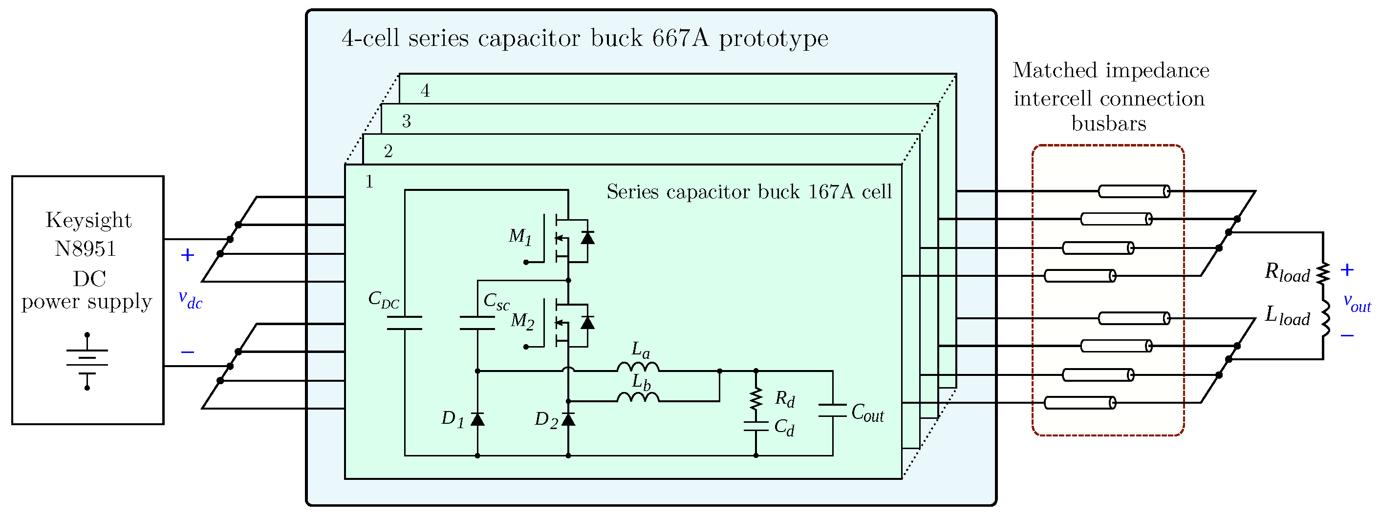
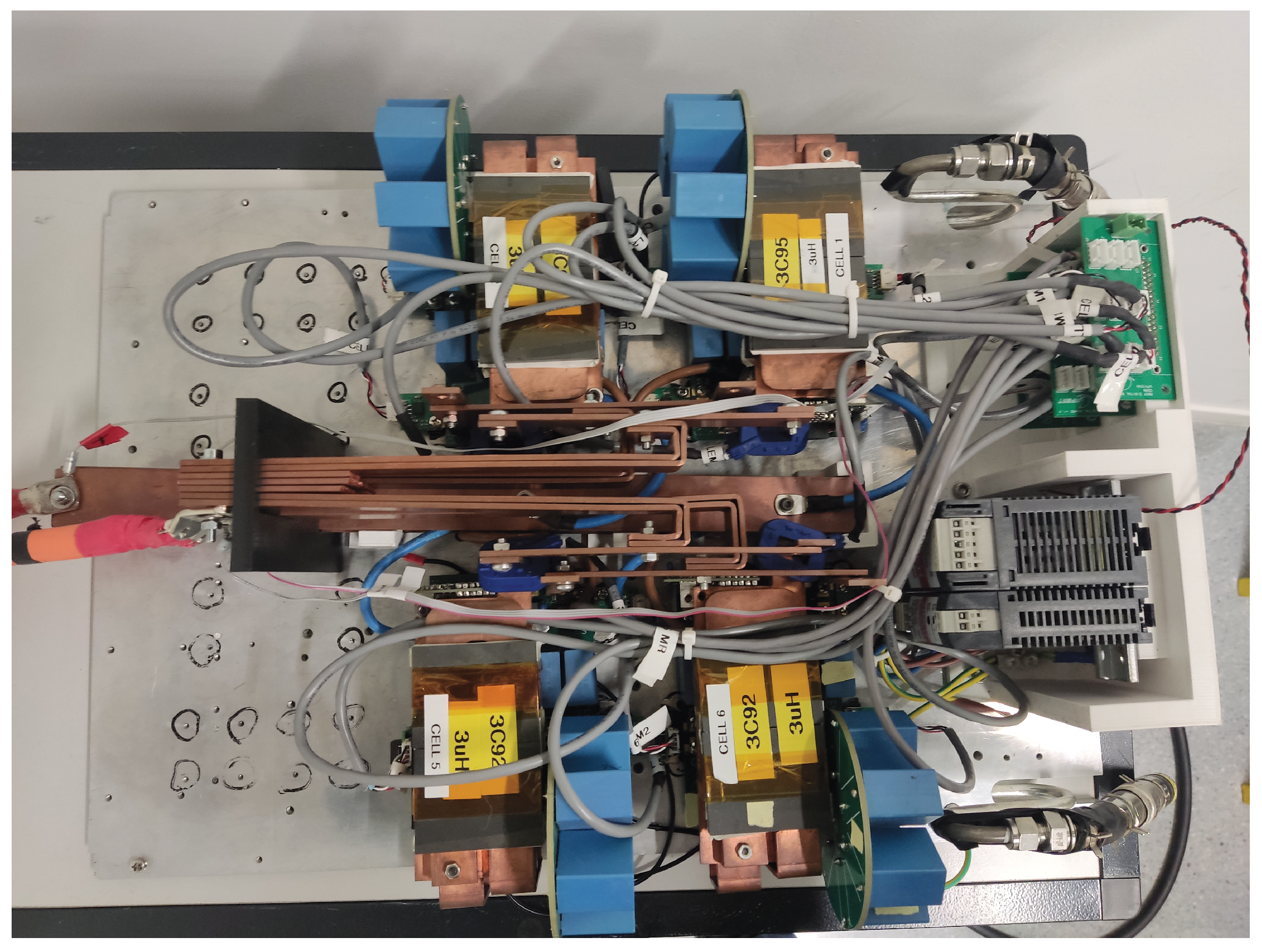
6.1. Experimental Platform Description

The proposal is experimentally validated using the high-current four-phase SC DC/DC converter prototype shown in Figure 10. Regarding power semiconductors, IXTN660N04T4 MOSFETs ( I D = 660 A, V D S S = 40 V, R d s , o n = 0.85 m Ω , SOT-227 package) and DSS2X121-0045B diodes ( I F = 120 A × 2, V R R M = 45 V, R F = 2.6 m Ω , SOT-227 package) are used. Due to the designed matched impedance intercell connection busbars (Figure 6 and Figure 10), all the cell units provide almost equivalent performance. The most relevant parameters of the power system and its controller are summarized in Table 2. A comprehensive description of the hardware platform can be found in [23]. An OPAL-RT OP4200 rapid control prototyping (RCP) platform is used to implement the fault diagnosis and fault-tolerant control algorithms. The RCP system has a XilinX Zynq 7030 (Kintex 7 FPGA and dual-core ARM9TM processor at 1 GHz), a 16 channel OP4240-1 analog input cassette (16 bit ADCs, 2.5 μs maximum conversion time), and a 32 channel OP4260-1 digital output cassette.
The proposed algorithms are implemented in the FPGA following a model-based design (MBD) approach. To accomplish this, the XilinX System Generator (XSG) and Real Time XSG toolboxes are utilized in the Matlab/Simulink environment. We conduct a comprehensive set of virtual tests, where a system model is employed as an executable specification. Finally, the VHDL and the corresponding bitstream are automatically generated through XilinX Vivado.

6.2. Fault Detection Performance Under Healthy Conditions

The proposed fault detection and diagnosis solution is tested first under healthy operation conditions. This is performed to empirically tune the detection parameters c n t m a x , σ l o a d , t h and σ j , t h . These parameters are adjusted to 8, 100 A, and 10 A, respectively. With c n t m a x = 8 , the fault detection and diagnosis algorithm is able to detect the fault once a phase current drops below σ j , t h for eight consecutive switching periods, leading to a fast and reliable fault identification. Once these parameters are correctly set, no false positives are detected during the tests when the system is operated under healthy conditions.
As an example, Figure 11 illustrates the performance of the power system during a start-up process, where the system is activated at around t = 0.75 s, producing a step-up in v o u t * , from 0 V to 1 V, and then a step-down, at around t = 0.75 s, from 1 V to 0.5 V (blue line in Figure 11). Satisfactory voltage regulation (Figure 11a) and current balancing (Figure 11b) responses are simultaneously achieved, and no fault flag is raised in the steady state or during transients (Figure 11c).

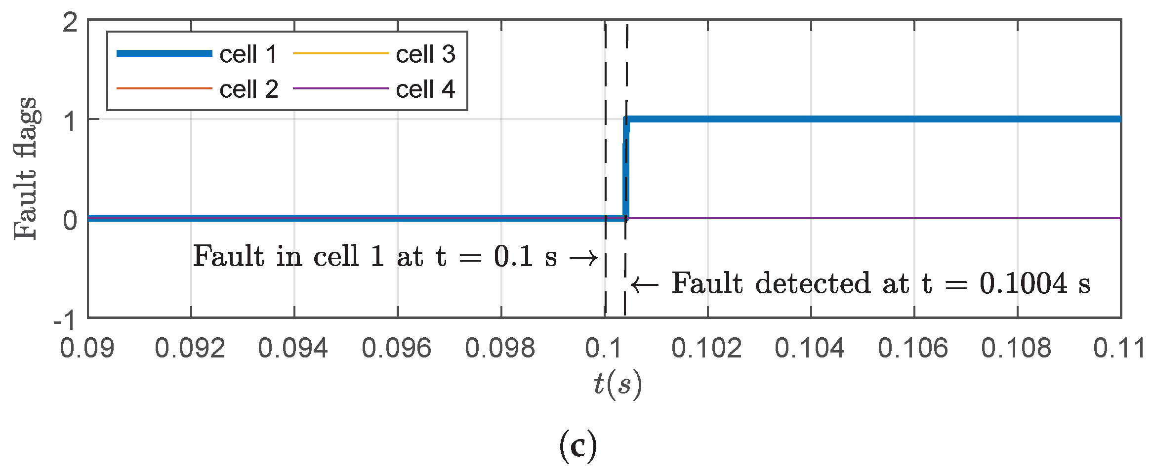
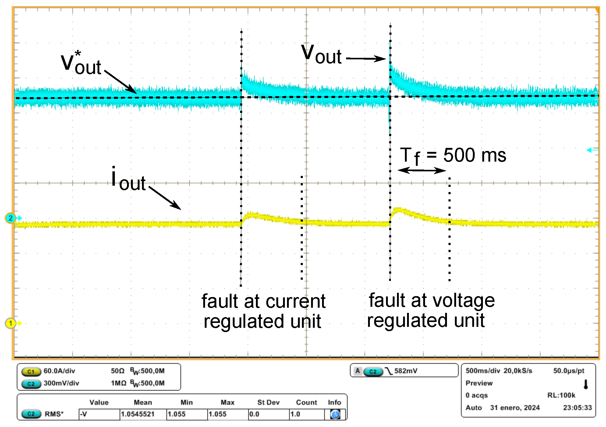
6.3. Fault Detection, Diagnosis, and Control Reconfiguration During Faults

Figure 12 and Figure 13 experimentally exemplify the performance of the system when two consecutive faults are produced: a fault in a current-regulated slave sub-converter and a fault in the voltage-regulated master sub-converter. To emulate the open-circuit faults produced by hypothetical driver circuitry errors, the top side M 1 MOSFETs’ firing pulses of sub-converters 1 and 4 are manually disabled from the OPAL-RT system’s console.
A constant voltage reference of v o u t * = 1 V is set for this test (blue line in Figure 12a). Once the first fault is induced, the output current of the corresponding sub-converter (number 4) drops to zero almost immediately (Figure 12d) as theoretically predicted. Then, the voltage- and current-balancing regulation responses experience significant perturbations (Figure 12a,b). Due to the proposed fault detection and diagnosis algorithm, the first fault is detected within a few modulation periods (Figure 12c). Then, the controller is reconfigured, and a sub-optimal operation is resumed in around 500 ms. An almost equivalent performance under a voltage-regulated sub-converter fault is observed within the test at around t = 2.25 s. The short transient current peaks of around 125 A and 150 A generated at the fault instants are not problematic for the integrity of the prototype, as to reduce the long-term thermal fatigue, the current ratings of the selected power semiconductors are far above the nominal values of the powering application (Section 6.1).
To complement the previously presented experimental results, which were registered in the OPAL-RT system through its sensors and ADCs, Figure 13 shows an oscilloscope capture of v o u t and i o u t for the same exact fault test. As expected, equivalent results are obtained.
Experimentally, in the presence of faults, more prolonged transients are found in the voltage and current responses than those obtained in the simulation (Figure 7 vs. Figure 12). This is due to the fact that the settling time of the voltage regulation loop is adjusted to 1 s in the experimental set-up, according to the real system specifications (note that the settling time is reduced in the simulation to shorten the time frame to be simulated and minimize the computational burden of the model). Finally, it is worth noting that the obtained perturbation in i o u t (Figure 13), although low, is noticeable. An inductive load of 50 μH is used to conduct the experimental tests. However, it must be borne in mind that, for the final application, L m a g = 255 mH. Thus, as previously justified in Section 5.4, it is expected that the corresponding perturbation is negligible in magnitude.

7. Conclusions

In this work, a novel fault detection and diagnosis algorithm for open-switch fault identification in multiphase DC/DC converters was proposed. The algorithm only uses the currently available digital computational resources (FPGA) and sensing devices of the electromagnet powering converter prototype, and does not require conducting any hardware modification within the system. In addition, a post-fault control reconfiguration solution was also proposed in the context of a master–slave multiphase DC/DC control approximation, previously published by the authors. From the obtained simulation and experimental results, it is confirmed that the proposal complies with the particular powering application dynamic requirements. Thus, it can be concluded that this new fault-tolerant controller could provide extra reliability to the IT powering system. As no additional hardware is required, its implementation could be suitable for the final application (i.e., HL-LHC).
Although this solution was originally intended for particle acceleration applications, it could also be used for other digitally controlled applications which share similar dynamic requirements, where interleaved DC/DC converters are used, and where reliability and fault tolerance are a must.

Author Contributions

Writing—original draft preparation, Conceptualization, Investigation, Validation, Methodology, E.I.; Writing—review and editing, Conceptualization, A.A.; Writing—review and editing, Supervision, Funding acquisition, Project administration, I.M.d.A.; Writing—review and editing, Validation, A.O.-O.; Writing—review and editing, Validation, A.M.; Writing—review and editing, Supervision, Project administration, L.d.M. All authors have read and agreed to the published version of the manuscript.

Funding

This work was supported in part by CERN and APERT (UPV/EHU) within the HL-LHC project named “Collaboration in the Study of Power Converter Topologies for Inner Triplet magnets with Energy Recovery in the framework of the High Luminosity upgrade for the LHC at CERN” and also in part by the Government of the Basque Country within the fund for research groups of the Basque University system under Grant IT978-16.

Data Availability Statement

The data are contained within the article.

Conflicts of Interest

The authors declare no conflicts of interest.

References

  1. Coulinge, E.; Pittet, S.; Dujic, D. Design Optimization of Two-Quadrant High-Current Low-Voltage Power Supply. IEEE Trans. Power Electron. 2020, 35, 11602–11611. [Google Scholar] [CrossRef]
  2. Coulinge, E. High-Current Low-Voltage Power Supply for Superconducting Magnets. Ph.D. Thesis, École Pollytechnique Fédérale de Lausanne, Lausanne, Switzerland, 2020. [Google Scholar]
  3. Ibarra, E.; Arias, A.; Martínez de Alegría, I.; Otero, A.; de Mallac, L. Digital control of multiphase Series Capacitor Buck converter prototype for the powering of HL-LHC Inner Triplet magnets. IEEE Trans. Ind. Electron. 2021, 69, 10014–10024. [Google Scholar] [CrossRef]
  4. Wassinger, N.; Maestri, S.; Garcia Retegui, R.; Funes, M.; Antoszczuk, P.; Pittet, S. MOSFET selection for a 18ka modula power converter for HL-LHC inner triplet. Power Electron. Devices Compon. 2023, 6, 100048. [Google Scholar] [CrossRef]
  5. Cao, D.; Zhang, D.; Kolar, J.; Huber, J. Conceptualization of a cryogenic 250-A power supply for high-temperature-superconducting (HTS) magnets of future particle accelerators. In Proceedings of the International Conference on Power Electronics-ECCE Asia, Jeju, Republic of Korea, 22–25 May 2023; pp. 688–696. [Google Scholar]
  6. Asimakopoulos, P.; Papastergiou, K.; Thiringer, T.; Bongiorno, M.; Le Godec, G. On Vce method: In situ temperature estimation and aging detection of high-current IGBT modules used in magnet power supplies for particle accelerators. IEEE Trans. Ind. Electron. 2019, 66, 551–560. [Google Scholar] [CrossRef]
  7. Asimakopoulos, P.; Papastergiou, K.; Thiringer, T.; Bongiorno, M.; Le Godec, G. IGBT power stack integrity assessment method for high-power magnet supplies. IEEE Trans. Power Electron. 2019, 34, 11228–11240. [Google Scholar] [CrossRef]
  8. Redondo, L.; Kandratsyeu, A.; Barnes, M. Marx Generator Prototype for Kicker Magnets Based on SiC MOSFETs. IEEE Trans. Plasma Sci. 2018, 46, 3334–3339. [Google Scholar] [CrossRef]
  9. Toscani, A.; Santoro, D.; Delmonte, N.; Cova, P.; Concari, C.; Lanza, A. CHARM facility remotely controlled platform at CERN: A new fault-tolerant redundant architecture. Microelectron. Reliab. 2020, 115, 113950. [Google Scholar] [CrossRef]
  10. Qingchuan, H.; Wenhua, C.; Jun, P.; Ping, Q. A prognostic method for predicting failure of dc/dc converter. Microelectron. Reliab. 2017, 74, 27–33. [Google Scholar] [CrossRef]
  11. Ferreira Costa, L.; Liserre, M. Failure analysis of the dc-dc converter. A comprehensive survey of faults and solutions for improving reliability. IEEE Power Electron. Mag. 2018, 5, 42–51. [Google Scholar] [CrossRef]
  12. Henn, J.; Ludecke, C.; Laumen, M.; Beushausen, S.; Kalker, S.; van der Broeck, C.; Engelmann, G.; de Doncker, R. Intelligent gate drivers for future power converters. IEEE Trans. Power Electron. 2022, 37, 3484–3503. [Google Scholar] [CrossRef]
  13. Picot-Digoix, M.; Richardeau, F.; Blaquiere, J.; Vinnac, S.; Azzopardi, S.; Le, T. Quasi-flying gate concept used for short-circuit detection on SiC power MOSFETs based on a dual-port gate driver. IEEE Trans. Power Electron. 2023, 38, 6934–6938. [Google Scholar] [CrossRef]
  14. Ravyts, S.; Van den Broeck, G.; Hallemans, L.; Dalla Vecchia, M.; Driesen, J. Fuse-based short-circuit protection of converter controlled low-voltage DC grids. IEEE Trans. Power Electron. 2020, 35, 11694–11708. [Google Scholar] [CrossRef]
  15. Wu, J.; Wang, H.; Ma, M.; Chen, Q.; Liang, J. Mode analysis and fault-tolerant method of open-circuit fault for a three-level dual active bridge DC-DC converter. Microelectron. Reliab. 2023, 150, 115100. [Google Scholar] [CrossRef]
  16. Kumar, G.; Elangovan, D. Review on fault-diagnosis and fault-tolerance for DC-DC converters. IET Power Electron. 2020, 13, 1–13. [Google Scholar] [CrossRef]
  17. Poon, J.; Jain, P.; Spanos, C.; Panda, S.K.; Sanders, S. Fault prognosis for power electronics systems using adaptive parameter identification. IEEE Trans. Ind. Appl. 2017, 53, 2862–2870. [Google Scholar] [CrossRef]
  18. Pazouki, E.; Sozer, Y.; De Abreu-Garcia, A. Fault diagnosis and fault-tolerant control operation of nonisolated DC-DC converters. IEEE Trans. Ind. Appl. 2018, 54, 310–320. [Google Scholar] [CrossRef]
  19. Tang, S.; Yin, X.; Wang, D.; Zhang, C.; Shuai, Z.; Yang, X.; Shen, Z.J.; Wang, J. Detection and identification of power switch failures for fault-tolerant operation of flying capacitor Buck-boost converters. Microelectron. Reliab. 2018, 88–90, 1236–1241. [Google Scholar] [CrossRef]
  20. Kirshenboim, O.; Vekslender, T.; Peretz, M. Closed-Loop Design and Transient-Mode Control for a Series-Capacitor Buck Converter. IEEE Trans. Power Electron. 2019, 34, 1823–1837. [Google Scholar] [CrossRef]
  21. Chen, Z.; Zhang, C.; Wu, Y.; Chen, Y.; Zhang, C. Series-Capacitor-Based Buck PFC Converter With High Power Factor and Ultrahigh Step-Down Conversion Ratio. IEEE Trans. Ind. Electron. 2019, 66, 6895–6905. [Google Scholar] [CrossRef]
  22. Bui, D.; Cha, H.; Nguyen, V. Asymmetrical PWM series-capacitor high-conversion-ratio DC-DC converter. IEEE Trans. Power Electron. 2021, 36, 8628–8633. [Google Scholar] [CrossRef]
  23. Otero-Olavarrieta, A.; Matallana, A.; Martínez de Alegría, I.; Ibarra, E.; Arias, A.; de Mallac, L.; Pittet, S. Hardware design of a high-current, high step-down ratio Series Capacitor Buck converter prototype for slow-ramped powering of High-Luminosity Large Hadron Collider inner triplet superconducting electromagnets. Appl. Energy 2024, 371, 123730. [Google Scholar] [CrossRef]
  24. Konstantopoulou, K.; Hurte, J.; Fleiter, J.; Ballarino, A. Electro-magnetic performance of MgB2 cables for the high current transmission lines at CERN. IEEE Trans. Appl. Supercond. 2019, 29, 1–5. [Google Scholar] [CrossRef]
  25. Younsi, M.; Bendali, M.; Azib, T.; Larouci, C.; Marchand, C.; Coquery, G. Current-sharing control techinique of interleaved buck converter for automotive applications. In Proceedings of the IET International Conference on Power Electronics, Machines and Drives (PEMD), Manchester, UK, 8–10 April 2014; pp. 1–6. [Google Scholar]
  26. Utkin, V.; Guldner, J.; Shi, J. Sliding Mode Control in Electro-Mechanical Systems; CRC Press: Boca Raton, FL, USA, 2009. [Google Scholar]
  27. Repecho, V.; Biel, D.; Ramos-Lara, R.; Garcia Vega, P. Fixed-switching frequency interleaved sliding mode eight-phase synchronous Buck converter. IEEE Trans. Power Electron. 2018, 33, 676–688. [Google Scholar] [CrossRef]
  28. Ribeiro, E.; Marques Cardoso, A.; Boccatelli, C. Open-circuit fault diagnosis in interleaved DC-DC converters. IEEE Trans. Power Electron. 2014, 29, 3091–3102. [Google Scholar] [CrossRef]
  29. Gleissner, M.; Bakran, M. Design and control of fault-tolerant nonisolated multiphase multilevel DC-DC converters for automotive power systems. IEEE Trans. Ind. Appl. 2016, 52, 1785–1795. [Google Scholar]
  30. Khojet El Khil, S.; Jlassi, I.; Estima, J.; Mrabet-Bellaaj, N.; Marques Cardoso, A. Detection and isolation of open-switch and current sensor faults in PMSM drives, through stator current analysis. In Proceedings of the IEEE International Symposium on Diagnostic for Electrical Machines, Power Electronics and Drives (SDEMPED), Tinos, Greece, 29 August–1 September 2017; pp. 373–379. [Google Scholar]
  31. Campos-Delgado, D.; Pecina-Sanchez, J.; Espinoza-Trejo, D.; Arce-Santana, E. Diagnosis of open-switch faults in variable speed drives by stator current analysis and pattern recognition. IET Electr. Power Appl. 2013, 7, 509–522. [Google Scholar] [CrossRef]
Figure 1. Sub-converter buck architectures for electromagnet powering: (a) standard buck stage sub-converter. (b) SC-based buck stage sub-converter.
Electronics 14 00924 g001
Figure 2. Cascaded multiphase DC/DC control architectures: (a) conventional cascaded configuration; (b) cascaded configuration with current sharing regulation loop.
Electronics 14 00924 g002
Figure 3. Master–slave multiphase buck converter control approach based on the application of decoupling matrix T .
Electronics 14 00924 g003
Figure 4. Block diagram of the proposed controller: (a) fault detection and diagnosis algorithm; (b) fault-tolerant voltage and current balancing algorithm including the fault detection block.
Electronics 14 00924 g004
Figure 5. Oversampling pattern for the sub-converter’s output current with a sampling time of T s w / 4 to obtain their averaged values at each k-th instant.
Electronics 14 00924 g005
Figure 6. Simplified diagram of the interconnection layout between the SC buck cells.
Electronics 14 00924 g006
Figure 7. Performance of the proposed fault-tolerant algorithm (simulation results) with an open-circuit fault in a master (voltage-regulated) cell: (a) output voltage response; (b) current response; (c) per-cell fault detection flags.
Electronics 14 00924 g007aElectronics 14 00924 g007b
Figure 8. Performance of the proposed fault-tolerant algorithm (simulation results) with an open-circuit fault in slave (current-regulated) cell: (a) output voltage response; (b) current response; (c) per-cell fault detection flags.
Electronics 14 00924 g008
Figure 9. Total output current for laboratory output inductance of 50 μH (blue line) vs. final circuit inductance of 0.255 H (red line).
Electronics 14 00924 g009
Figure 10. Prototype of the SC-based multiphase DC/DC used to validate the proposed fault detection and fault-tolerant algorithms.
Electronics 14 00924 g010
Figure 11. Operation of the multiphase DC/DC converter during start-up and step-up and step-down transients when working in healthy mode: (a) output voltage vs. reference voltage; (b) per-phase currents; (c) fault flags.
Electronics 14 00924 g011
Figure 12. Experimental results (II): power converter operation under the occurrence of two consecutive open-circuit faults at current-controlled cell number four ( t 1 s) and voltage-controlled cell number one ( t 2.25 s): (a) output voltage vs. reference voltage; (b) per-phase currents; (c) fault flags; (d) details of per-phase current evolution under an open-phase fault in slave sub-converter number four [zoomed area 1 of subfigure (b)]; (e) details of per-phase current evolution under an open-phase fault in master sub-converter [zoomed area 2 of subfigure (b)].
Electronics 14 00924 g012
Figure 13. Experimental results (and III): oscilloscope capture of the two consecutive open-circuit fault scenarios.
Electronics 14 00924 g013
Table 1. Main operating parameters of the developed single converter unit for IT magnet powering.
ParameterSymbolValueUnits
Number of interleaved SC cellsN4-
Rated total output current i o u t 667A
Output current variation rate during transients Δ i o u t / Δ t 16A/s
Maximum output voltage (emergency operation) v o u t , m a x 10V
Rated output voltage (typical value) * v o u t , r a t e d 4V
Maximum output power (emergency operation) P o u t , m a x 6.67kW
Rated output power (typical value) * P o u t , r a t e d 2.67kW
* The exact value will depend on R w .
Table 2. Main parameters of the simulation platform/experimental power system and its controller.
Power System Parameters
Number of cells (N)4Switching freq. ( f s w )50 kHz
Controller frequency ( f c )50 kS/sInput voltage ( V b a t )24 V
DC-link capacitor ( C d c )100 μFSeries capacitor ( C s c )400 μF
Output capacitor ( C o u t )4.7 mFPer-cell induc. ( L a , L b )3.5 μH
Load inductor parametersControl parameters
Inductance ( L l o a d )50 μHVoltage S T 2 % (sim.)50 ms
Load resistance ( R l o a d )5 m Ω Voltage S T 2 % (exp.)1 s
Current S T 2 % I 5 ms
Disclaimer/Publisher’s Note: The statements, opinions and data contained in all publications are solely those of the individual author(s) and contributor(s) and not of MDPI and/or the editor(s). MDPI and/or the editor(s) disclaim responsibility for any injury to people or property resulting from any ideas, methods, instructions or products referred to in the content.

