Article

4 × 4 Wideband Slot Antenna Array Fed by TE440 Mode Based on Groove Gap Waveguide

National Key Laboratory of Antennas and Microwave Technology, Xidian University, Xi’an 710071, China
*
Author to whom correspondence should be addressed.
Electronics 2025, 14(4), 813; https://doi.org/10.3390/electronics14040813
Submission received: 2 January 2025 / Revised: 17 February 2025 / Accepted: 18 February 2025 / Published: 19 February 2025
(This article belongs to the Special Issue Antenna and Array Design for Future Sensing and Communication System)

Abstract

:
A 4 × 4 wideband millimeter-wave (mmWave) slot array antenna excited by the TE440 mode based on the groove gap waveguide is presented in this paper. A vertical waveguide located in the center of the cavity and two ridges are used to excite the TE440 mode. In addition, a pair of corrugations acting as the soft surface are added on the top of the array antenna to improve the gain. A 4 × 4 prototype is fabricated and measured. The measured and simulated results are in great agreement. The measured results show that the proposed array antenna achieved an impedance bandwidth (|S11| < −10 dB) of 26.7% from 26.14 to 34.2 GHz, and the maximum gain is 17.7 dBi. The proposed array antenna avoids the complicated feeding network, allowing us to reduce the manufacturing cost.

1. Introduction

Gap waveguide (GW) technology has recently emerged as a promising option for millimeter-wave (mmWave) planar array antennas, offering advantages such as reduced losses, simplified assembly, and inherent self-packaging capabilities when compared to traditional transmission line approaches [1]. As a result, a variety of array antennas have been designed utilizing GW technology [2,3]. Most of these antennas are fed by a double-layered corporate-feed network, which is a promising method to achieve high gain and wide bandwidth characteristics, but it also increases the overall manufacturing cost and the transmission losses [4]. Nevertheless, in most applications, array antennas with a low profile are favored. To deal with the low-profile feature, single-layered array antennas have been designed based on either series-feed or corporate-feed networks [5]. However, these antennas still suffer from the complex feeding network.
Recently, using high-order modes in the array antennas has been proven to be a good way to simplify the topology of the feeding network, or even avoid complicated feeding networks [6,7,8,9,10,11,12,13]. In [11], a four-by-four slot array antenna was proposed, utilizing the TE440 mode and based on the groove gap waveguide (GGW) structure. It was excited by a single coaxial probe and exhibited an impedance bandwidth of 16% along with a 3-dB gain bandwidth of 9.3%. However, the radiation patterns were not symmetric due to the unwanted high-order modes excited by the asymmetric feeding structure. In [12], the high-order mode TE440 was employed to feed a four-by-four GGW slot array antenna, which achieved a circularly polarized (CP) performance with the help of a polarizing layer at 28 GHz. A Ka-band 4 × 4 slot array antenna with glide-symmetric GW technology used the TE40 mode excitation and achieved a maximum total efficiency of 78% [13]. However, it needs a TE10-TE20 mode converter, which takes up a large amount of space. Thus, the realization of a slot array with the merits of both GW technology and high-order mode excitation, as well as a simple structure and a good performance, including wide bandwidth and high gain, presents a significant challenge.
In this research, the high-order mode TE440 and GW technology are employed to create a 4 × 4 wideband slot array antenna at the mmWave band. Without the feeding network, the antenna has a simple structure and low manufacture cost. In addition, a stable broadside beam and symmetric radiation patterns within a wide bandwidth are achieved by using the excitation structure of a vertical waveguide and two ridges. The gain is improved by adding two corrugations as the soft surface at the antenna’s top. The proposed slot array antenna has been designed and fabricated, showing an impedance bandwidth of 26.7%.

2. Antenna Design and Configuration

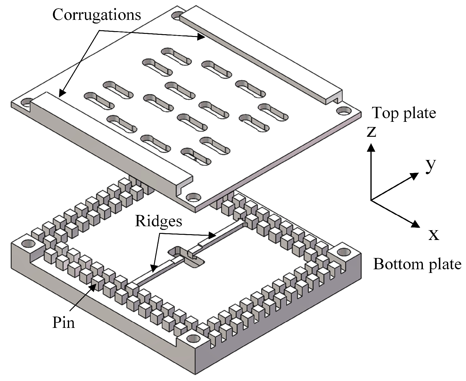
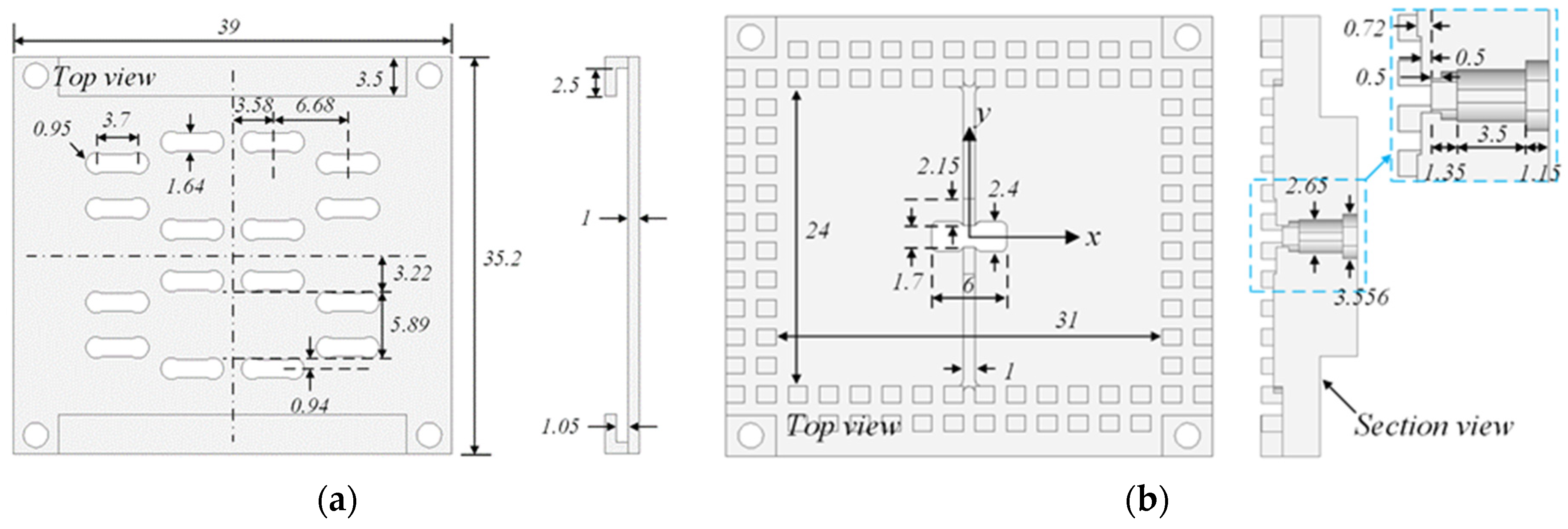
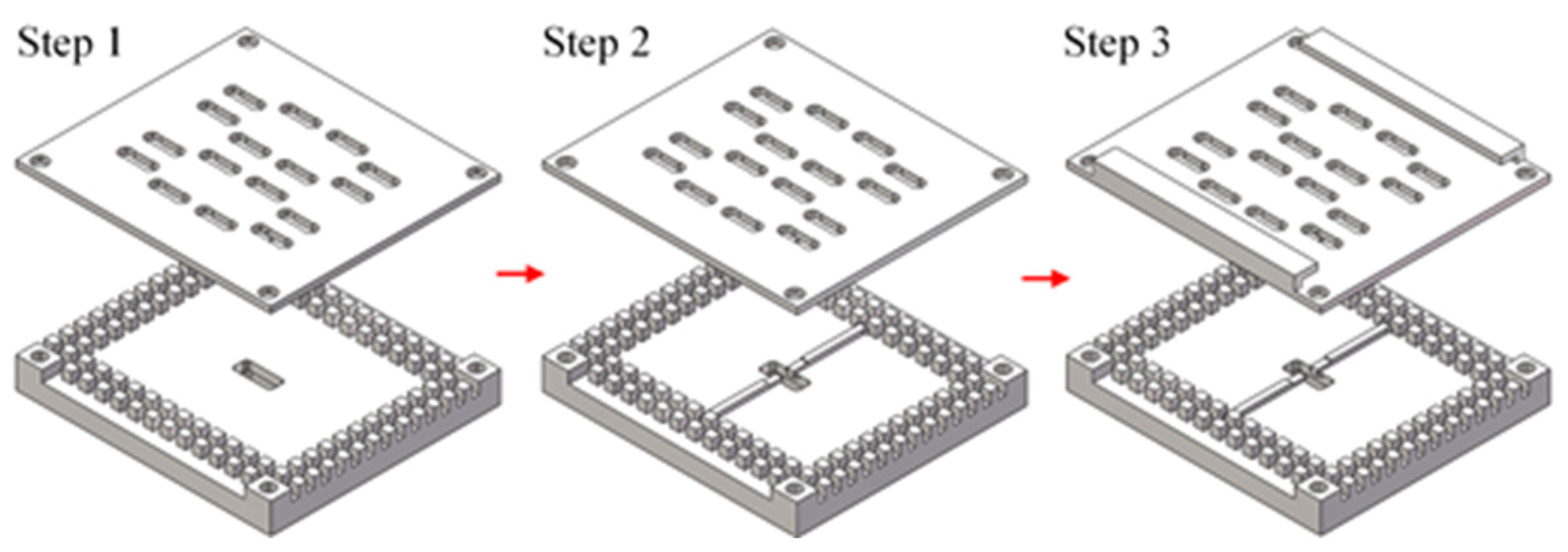
2.1. Antenna Configuration

Figure 1 illustrates the geometry of the proposed 4 × 4 slot array antenna created using the TE440 mode. The antenna comprises two metal plates: (1) the top plate and (2) the bottom plate. The top plate contains 16 dumbbell-shaped slots, which offer a broader bandwidth compared to rectangular slots, and features a pair of corrugations on its upper surface to create a soft surface. The bottom plate’s upper surface hosts two rows of pins, serving as the unit cells for the artificial magnetic conductor (AMC), which forms the sidewalls of the groove gap waveguide (GGW) cavity. Table 1 shows the dimensions of the unit cell. The dispersion diagram, created using the eigenmode solver in CST Studio Suite, is shown in Figure 2. The stopband spans from 14.8 to 76.7 GHz, ensuring that energy does not leak from the cavity within this range despite a 0.05 mm air gap between the pins and the top plate. A vertical waveguide, positioned at the center of the cavity, excites the TE440 mode, while a pair of ridges is placed to enhance impedance matching. One ridge end is located at the center of the cavity’s broad rim, and the other is inserted into the waveguide at a height of 0.5 mm.
Figure 3 illustrates the geometry of the two metal plates. As shown in Figure 3b, a three-step transition from the waveguide at a dimension of 6 × 2.4 mm2 to the standard waveguide WR-28 is used for measurement.

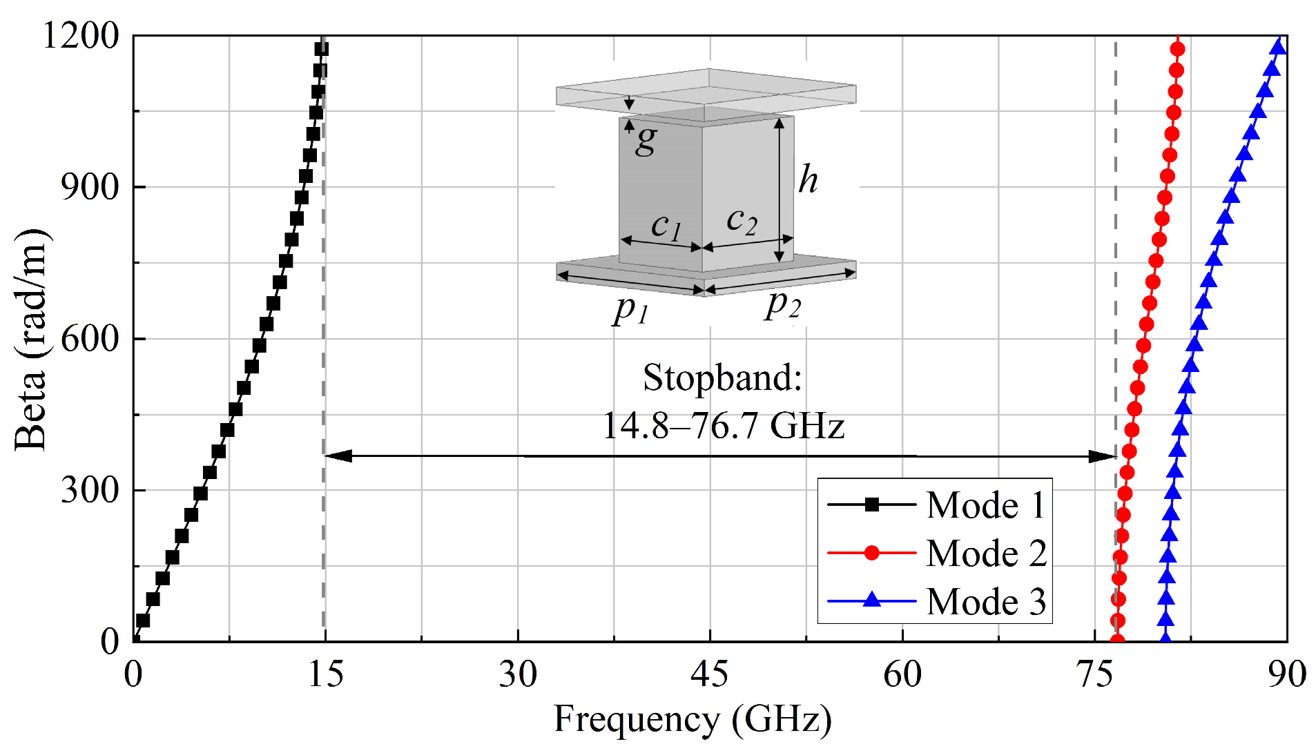
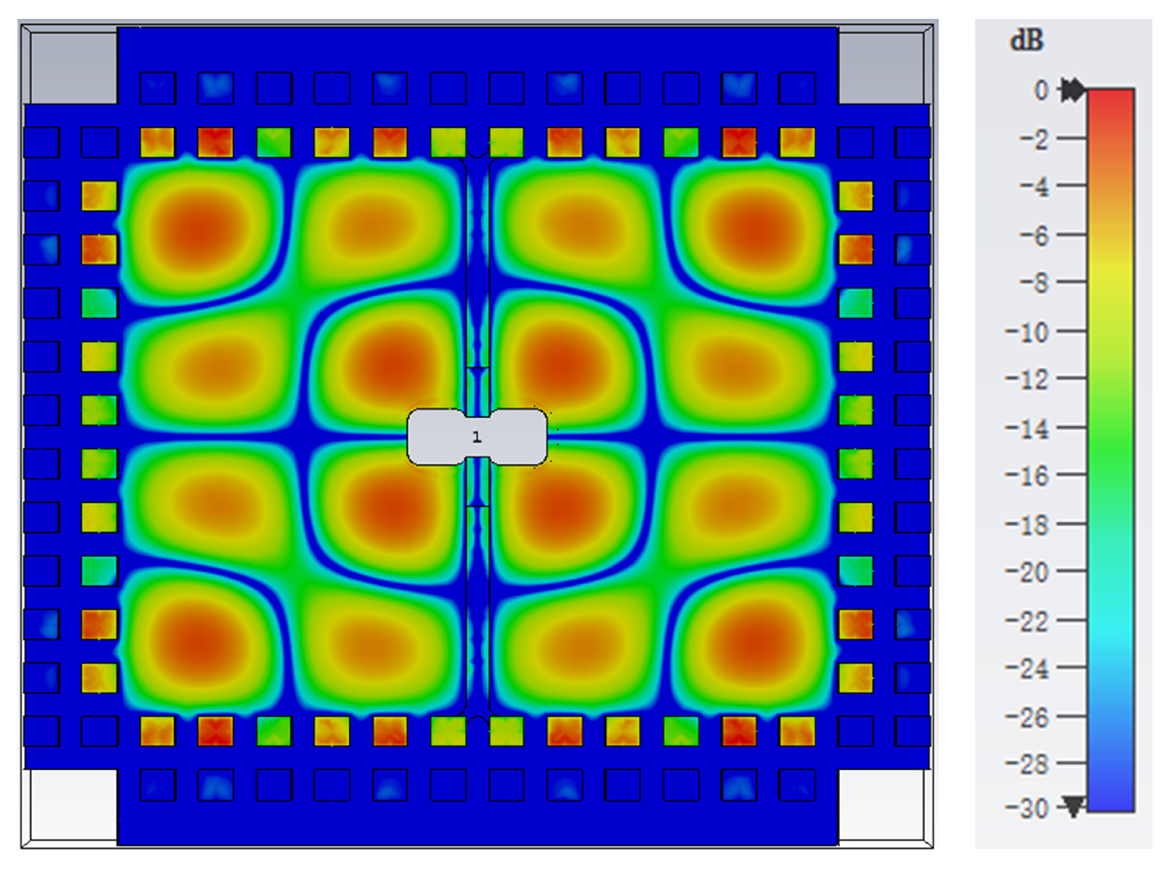
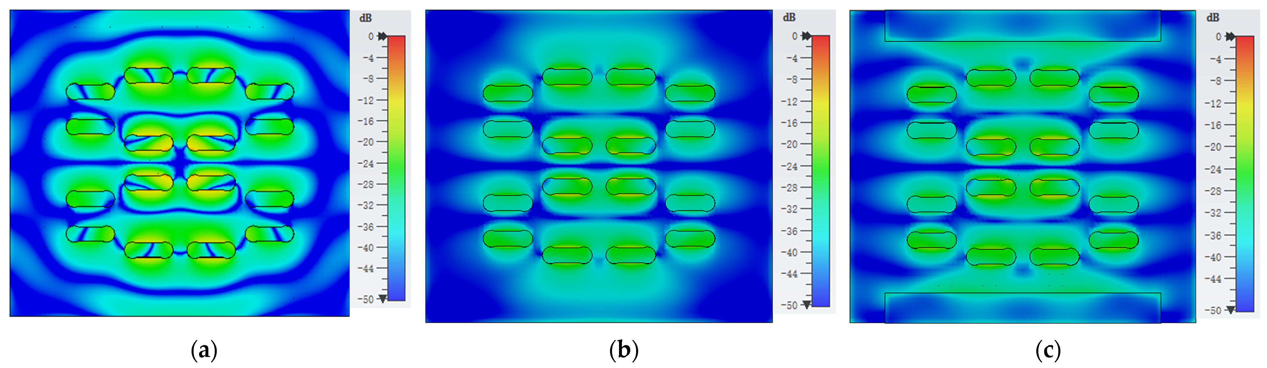
2.2. Working Principle

The dumbbell-shaped slots are placed with a spacing of approximately half a wavelength and are positioned alternately on opposite sides of the standing wave peak centerlines. When the energy is excited in the vertical waveguide, it propagates into the GGW cavity. The high-order TE440 mode is then excited within the cavity and radiated in phases through the 16 slots. It should be noted that the excitation structure and the chosen high-order mode are related to the stability of the broadside beam. Different from the excitation using a single coaxial probe, which may excite the unwanted odd high-order modes due to the asymmetric excitation structure, the excitation using a vertical waveguide is symmetric, considering both the xz- and yz-planes. Thus, the odd high-order modes are avoided, which ensures symmetric radiation patterns to the maximum extent. The size of the cavity is 31 × 24 mm2, and the corresponding resonance frequency of the TE440 mode, calculated using the eigenmode solver in CST Studio Suite, is 31.62 GHz. Figure 4 illustrates the simulated E-field distribution within the GGW cavity without slots at 31.62 GHz. The difference between the simulated distribution and the theoretical ideal distribution may be due to the existence of the feeding waveguide.
To explain the design process of the proposed 4 × 4 slot array antenna, three steps are shown in Figure 5. Step 1 is a 4 × 4 slot array fed by a vertical waveguide. In Step 2, a pair of ridges is placed on the upper surface of the bottom plate. In Step 3, a pair of corrugations is added on the upper surface of the top plate. The simulated results of the antenna from Steps 1–3 are given in Figure 6. It can be seen that the slot array in Step 1 achieves a wide impedance bandwidth covering 25.3–34.6 GHz and a gain above 15 dBi from 28.2–34.75 GHz. However, the curve of the reflection coefficient is very close to −10 dB. After adding the two ridges that act as a transition from the WR-28 waveguide to the GGW cavity layer, the impedance matching characteristics are significantly improved to be below −15 dB. In addition, the electric field distribution in the cavity is also improved with the adding of the ridges due to the better transition, thus contributing to a gain enhancement of around 0.5 dB. Step 3 uses two corrugations with a depth of about a quarter-wavelength as the soft surface to reduce the surface wave. Figure 7 shows the simulated maximum electric field distribution on the top surface of the proposed array antenna at 29 GHz, comparing configurations with and without ridges and corrugations. It can be seen that without the corrugations, some of the energy, acting as the surface wave, propagates in the ±y direction to the back of the antenna. After adding the two corrugations, the surface wave is stopped due to the high impedance characteristics of the soft surface. Thus, the gain is further increased, especially at lower band, and the impedance bandwidth undergoes little change.

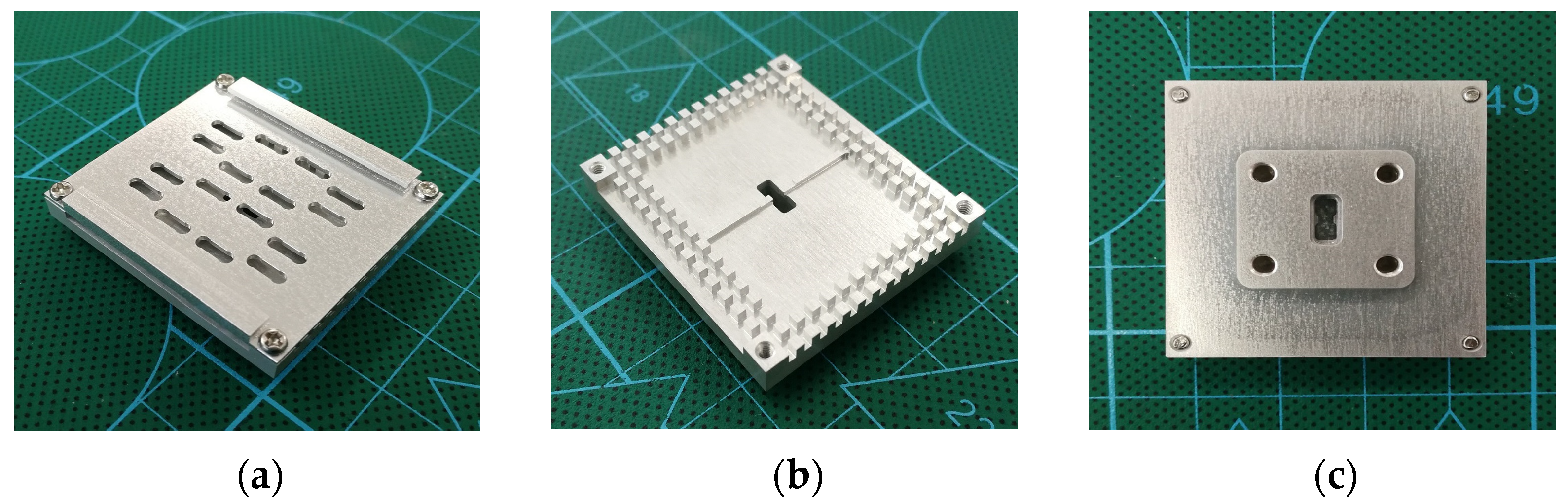
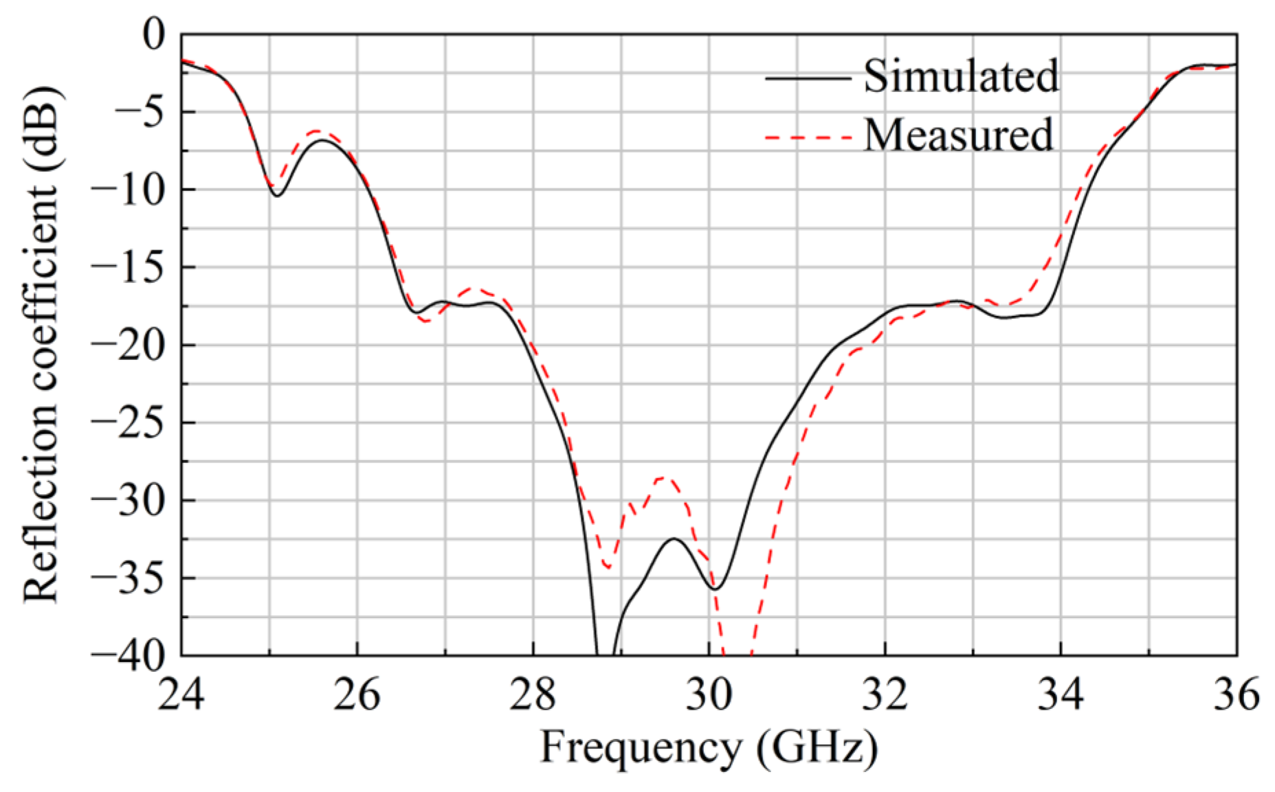
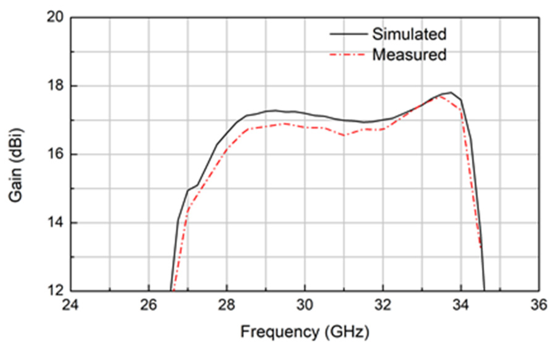
3. Measurement and Discussion

The newly introduced 4 × 4 wideband slot array antenna was fabricated by using computer numerical control (CNC) milling with a fabrication tolerance of ±0.02 mm. The size of the proposed array antenna is 39 × 35.2 × 10.75 mm3. Figure 8 shows photographs of the proposed array antenna. It can be seen that the antenna can be easily assembled by using four screws due to the utilization of GW technology. The reflection coefficient was measured by using an Agilent E8363B vector network analyzer with a WR-28 calibrator kit. Figure 9 exhibits the measured and simulated reflection coefficients, which are in good agreement. It can be seen that the measured impedance bandwidth, with a reflection coefficient below −10 dB, is 26.7% from 26.14 GHz to 34.2 GHz.
The radiation patterns of the array antenna were measured using the far-field setup in an anechoic chamber. Figure 10 presents the measured and simulated E- and H-plane radiation patterns at 27, 30.5, and 34 GHz. The measured co-polar patterns show good agreement with the simulated co-polar patterns. It should be noted that a high sidelobe level of −5 dB in the H-plane at 27 GHz is due to unwanted high-order modes. In spite of this, the wideband antenna achieves a stable broadside beam and symmetric patterns, which benefit from the symmetric excitation structure. The measured cross polarization levels are below −26 dB. The measured and simulated gains are given in Figure 11. The measured 3-dB gain bandwidth is 22.8% from 27.25 GHz to 34.25 GHz, with the maximum measured gain reaching 17.7 dBi at 33.5 GHz.
Table 2 compares the proposed design with previously reported designs that use high-order modes. Although the antenna in [9] possesses a wide bandwidth, its radiation patterns are not symmetric due to the excitation of a single coaxial probe. Compared with those created with GW technology, the newly introduced slot array antenna realizes the widest bandwidth for both impedance and 3-dB gain.

4. Conclusions

In this paper, a 4 × 4 wideband slot array antenna is proposed that adopts the high-order mode TE440 and GW technology. A vertical waveguide located in the center of the cavity and two ridges are used to excite the TE440 mode. Thus, the slot array antenna obtains a stable broadside beam and symmetric patterns across a broad frequency range. Two corrugations, used as a soft surface, are employed to minimize the surface wave to improve gain enhancement. The fabricated prototype shows a 26.7% measured impedance bandwidth, with a peak gain of 17.7 dBi. The simple structure and wide bandwidth make it promising even for upper mm-wave applications.

Author Contributions

Conceptualization, Y.S. and T.Z.; data curation, H.Z.; formal analysis, T.Z.; funding acquisition, T.Z.; investigation, Y.S.; methodology, T.Z.; project administration, L.C.; resources, L.L.; software, H.Z.; supervision, L.C.; validation, Y.S., L.L. and L.C.; visualization, Y.S.; writing—original draft, T.Z.; writing—review and editing, Y.S. All authors have read and agreed to the published version of the manuscript.

Funding

This work was carried out within the Key Research and Development Program of Shaanxi, with grant no. 2024GH-ZDXM-43 and no. 2024GH-ZDXM-11.

Data Availability Statement

All data are contained within the article.

Conflicts of Interest

The authors declare no conflicts of interest.

Abbreviations

The following abbreviations are used in this manuscript:
mmWaveMillimeter-wave
GWGap waveguide
GGWGroove gap waveguide
CPCircularly polarized
AMCArtificial magnetic conductor
CNCComputer numerical control

References

  1. Kildal, P.-S.; Zaman, A.U.; Rajo-Iglesias, E.; Alfonso, E.; Valero-Nogueira, A. Design and Experimental Verification of Ridge Gap Waveguide in Bed of Nails for Parallel-Plate Mode Suppression. IET Microw. Antennas Propag. 2011, 5, 262–270. [Google Scholar] [CrossRef]
  2. Zhang, T.; Chen, L.; Moghaddam, S.M.; Zaman, A.U.; Yang, J. Ultra-wideband Linearly Polarised Planar Bowtie Array Antenna with Feeding Network Using Dielectric-based Inverted Microstrip Gap Waveguide. IET Microw. Antennas Propag. 2020, 14, 485–490. [Google Scholar] [CrossRef]
  3. Ferrando-Rocher, M.; Herranz-Herruzo, J.I.; Valero-Nogueira, A.; Bernardo-Clemente, B.; Zaman, A.U.; Yang, J. 8 × 8 Ka-Band Dual-Polarized Array Antenna Based on Gap Waveguide Technology. IEEE Trans. Antennas Propag. 2019, 67, 4579–4588. [Google Scholar] [CrossRef]
  4. Vosoogh, A.; Kildal, P.-S.; Vassilev, V. Wideband and High-Gain Corporate-Fed Gap Waveguide Slot Array Antenna with ETSI Class II Radiation Pattern in V-Band. IEEE Trans. Antennas Propag. 2017, 65, 1823–1831. [Google Scholar] [CrossRef]
  5. Liu, J.; Vosoogh, A.; Zaman, A.U.; Yang, J. A Slot Array Antenna With Single-Layered Corporate-Feed Based on Ridge Gap Waveguide in the 60 GHz Band. IEEE Trans. Antennas Propag. 2019, 67, 1650–1658. [Google Scholar] [CrossRef]
  6. Asaadi, M.; Sebak, A. High-Gain Low-Profile Circularly Polarized Slotted SIW Cavity Antenna for MMW Applications. Antennas Wirel. Propag. Lett. 2017, 16, 752–755. [Google Scholar] [CrossRef]
  7. Cao, F.; Yang, D.; Pan, J.; Geng, D.; Xiao, H. A Compact Single-Layer Substrate-Integrated Waveguide (SIW) Monopulse Slot Antenna Array. Antennas Wirel. Propag. Lett. 2017, 16, 2755–2758. [Google Scholar] [CrossRef]
  8. Han, W.; Yang, F.; Long, R.; Zhou, L.; Yan, F. Single-Fed Low-Profile High-Gain Circularly Polarized Slotted Cavity Antenna Using a High-Order Mode. Antennas Wirel. Propag. Lett. 2016, 15, 110–113. [Google Scholar] [CrossRef]
  9. Han, W.; Yang, F.; Ouyang, J.; Yang, P. Low-Cost Wideband and High-Gain Slotted Cavity Antenna Using High-Order Modes for Millimeter-Wave Application. IEEE Trans. Antennas Propag. 2015, 63, 4624–4631. [Google Scholar] [CrossRef]
  10. Wu, P.; Liao, S.; Xue, Q. Wideband Excitations of Higher-Order Mode Substrate Integrated Waveguides and Their Applications to Antenna Array Design. IEEE Trans. Antennas Propag. 2017, 65, 4038–4047. [Google Scholar] [CrossRef]
  11. Talepour, Z.; Khaleghi, A. Groove Gap Cavity Slot Array Antenna for Millimeter Wave Applications. IEEE Trans. Antennas Propag. 2019, 67, 659–664. [Google Scholar] [CrossRef]
  12. Keivaan, A.; Oraizi, H.; Amini, A. Design of Circularly-Polarized Cavity-Backed Slot Array Antenna Using Higher-Order Mode Excitation Based on Gap Waveguide Technology. In Proceedings of the 2018 9th International Symposium on Telecommunications (IST), Tehran, Iran, 17–19 December 2018; pp. 535–537. [Google Scholar]
  13. Liao, Q.; Rajo-Iglesias, E.; Quevedo-Teruel, O. Ka -Band Fully Metallic TE40 Slot Array Antenna With Glide-Symmetric Gap Waveguide Technology. IEEE Trans. Antennas Propag. 2019, 67, 6410–6418. [Google Scholar] [CrossRef]
Figure 1. The geometry of the 4 × 4 slot array antenna introduced using TE440.
Electronics 14 00813 g001
Figure 2. The dispersion diagram of the unit cell.
Electronics 14 00813 g002
Figure 3. The geometry of the metal plates (in mm): (a) top plate and (b) bottom plate.
Electronics 14 00813 g003
Figure 4. The simulated E-field distribution within the GGW cavity without slots at 31.62 GHz.
Electronics 14 00813 g004
Figure 5. The evolution process of the newly introduced wideband 4 × 4 slot array antenna.
Electronics 14 00813 g005
Figure 6. The simulated results of the proposed 4 × 4 wideband slot array antenna after Steps 1–3: (a) reflection coefficient and (b) gain.
Electronics 14 00813 g006
Figure 7. The simulated maximum E-field distribution over the antenna’s top surface at 29 GHz: (a) without ridges and corrugations, (b) with ridges but without corrugations, and (c) with both ridges and corrugations.
Electronics 14 00813 g007
Figure 8. Photographs of the prototype: (a) from the oblique top, (b) from the oblique top (inside), and (c) from the bottom.
Electronics 14 00813 g008
Figure 9. The measured and simulated reflection coefficients of the newly introduced 4 × 4 wideband slot array antenna.
Electronics 14 00813 g009
Figure 10. The measured and simulated radiation patterns of the proposed 4 × 4 wideband slot array antenna: (a) 27 GHz, (b) 30.5 GHz, and (c) 34 GHz.
Electronics 14 00813 g010
Figure 11. The measured and simulated gains of the newly introduced slot array antenna.
Electronics 14 00813 g011
Table 1. Unit cell dimensions (in mm).
Parametersp1p2hc1c2g
Values 2.32.51.651.31.50.05
Table 2. A comparison between the proposed design and previously reported designs that use high-order modes.
Ref.Array
Scale
Feeding
Technology
Impedance
Bandwidth
3-dB Gain
Bandwidth
Max.
Gain (dBi)
[9]3 × 3 SIW>26%>14.1%13.8
[10]4 × 4 SIW15.2%>15.2%15.8
[11]4 × 4 GW16%9.3%18.0
[13]4 × 4 GW11.1%n.a.19.63
Our work4 × 4 GW26.7%22.817.7
n.a.: not available.
Disclaimer/Publisher’s Note: The statements, opinions and data contained in all publications are solely those of the individual author(s) and contributor(s) and not of MDPI and/or the editor(s). MDPI and/or the editor(s) disclaim responsibility for any injury to people or property resulting from any ideas, methods, instructions or products referred to in the content.

