Article

Multi-Risk Factor and Knowledge Entropy Framework for Alternating Current Arc Fault Detection

1
School of Electrical Engineering and Automation, Wuhan University, Wuhan 430072, China
2
College of Science and Engineering, James Cook University, Cairns, QLD 4878, Australia
*
Author to whom correspondence should be addressed.
Electronics 2025, 14(4), 708; https://doi.org/10.3390/electronics14040708
Submission received: 30 December 2024 / Revised: 25 January 2025 / Accepted: 10 February 2025 / Published: 12 February 2025

Abstract

:
This study addresses the significant challenges associated with detecting series AC arc faults, particularly in the context of diverse load types, coupled features, and the superimposed characteristics of arc signals. To overcome these complexities, a novel AC arc detection methodology is proposed, which leverages the construction of multiple risk factors. Specifically, the approach introduces three innovative risk factors: the abnormal distribution risk factor, the harmonic energy risk factor, and the abnormal pulse risk factor (collectively referred to as AHA). These factors are designed to extract the distinct characteristics of AC arc faults across varying operational scenarios. Furthermore, an expert knowledge-driven fusion framework based on information entropy (KE) is developed to integrate these risk factors, enhancing the robustness and precision of the detection process. Experimental validation conducted in low-voltage electrical environments demonstrates that the proposed AHA-KE model achieves high detection accuracy, effectively addressing the inherent challenges of arc fault detection in such settings.

1. Introduction

The increasing diversification of electrical appliances among urban residents has significantly enhanced their quality of life. However, there remains a notable lack of awareness regarding electrical safety. Electric arcs, often caused by unauthorized electrical connections, aging infrastructure, or damaged wiring, pose serious threats to residential electrical safety. These arcs can produce extremely high temperatures exceeding 5000 °C [1,2], significantly increasing the risk of electrical fires. Unfortunately, conventional protection devices are insufficient for effectively detecting electric arcs [3]. To address this critical issue, the International Electrotechnical Commission (IEC) has introduced Arc Fault Detection Devices (AFDDs), which have been implemented in Europe, China, and other countries [4]. Moreover, solid-state circuit breakers are an advanced technology for grid protection, designed to eliminate arcing. Unlike traditional mechanical circuit breakers, which rely on physical contacts, solid-state circuit breakers utilize semiconductor devices (such as transistors and diodes) to switch circuits, enabling rapid and reliable disconnection. Ongoing research in this field has significantly enhanced electrical safety [5,6].
According to statistics from the China Electrical Equipment Industry Association, the adoption rate of AFDDs in China remains relatively low, raising significant safety concerns regarding AC arc faults. To address these issues, researchers have explored various arc fault features for detecting such faults. These features include current sag, current spectrum, voltage gradient, high-frequency components of the current gradient, capacitive current, zero-crossing cutoff characteristics, and electromagnetic radiation.
Arc fault detection has been approached using various methods. In [7], current sag is analyzed, and the correlation between normal and fault frequency bands is leveraged to identify arc occurrences. While this method rigorously establishes a current sag model, it remains highly susceptible to interference from inductive devices. A different approach in [8] extracts arc characteristics from current spectra and employs a sparse representation algorithm for detection. It also introduces an online adjustment method for the regular order p, making it adaptable to various devices. However, when circuit power is excessively high and the line is nearly conductive, the algorithm may fail.
Magnetohydrodynamics is explored in [9] to enhance arc modeling, leading to a simplified approach for calculating arc voltage gradients and accurately estimating voltage gradients in low-voltage short arcs. Yet, aliasing effects caused by electrical devices are not considered. In [10], a Rogowski coil di/dt sensor is used to capture high-frequency arc characteristics, as high-frequency sampling preserves more arc-specific features. However, relying solely on threshold-based detection may lead to false positives.
Information entropy is utilized in [11] to reconstruct signal sequences and determine the characteristic frequency bands of arc current signals, effectively extracting arc features. Despite this, no specific detection methodology is provided. A security framework proposed in [12] detects arcs based on their zero-crossing characteristics, incorporating arc fault circuit interrupters (AFCIs) to enhance grid safety. Electromagnetic radiation is leveraged in [13,14] to distinguish arc signals from non-arc signals, followed by log-spectral distance classification and online monitoring on an embedded platform. Nonetheless, performance may degrade under complex conditions.
While these methods can reflect the occurrence of arc faults to some extent, the proliferation of nonlinear components and harmonic distortions caused by the increasing variety of user-side electrical appliances and the widespread application of power electronic devices complicate the distinction between arc and normal states. In such overlapping scenarios, feature aliasing among different load types often leads to unwanted tripping or missed detections. Furthermore, continuous combustion caused by excessive current remains particularly challenging to detect effectively.
To address this challenge, it is essential to develop a model capable of accurate arc fault identification. Recent studies have explored the application of artificial intelligence (AI) in arc detection. For instance, support vector machines (SVMs), classical AI models, have been applied to arc fault detection in photovoltaic DC systems [15]. This method utilizes the Hurst exponent to mitigate interference from power electronics noise and applies Empirical Mode Decomposition (EMD) to automatically extract the oscillatory frequencies of arc currents. This approach eliminates the need for prior knowledge of interference frequency ranges, which is typically required by traditional filters or wavelet transforms. However, in low-voltage AC scenarios, the characteristics of user electrical equipment often interfere with arc detection. Additionally, convolutional neural networks (CNNs) have been utilized to detect arc faults, achieving high detection accuracy. The TDV-CNN arc detection model proposed in [16] employs a time domain visualization method to extract deep features, achieving high-precision arc detection. However, it only considers faults in a single electrical device and does not account for the simultaneous operation of multiple devices. In [17], an adaptive convolutional network is introduced, leveraging generative adversarial networks to enhance carbonization path data, thereby improving model robustness. Yet, research on other fault types in AC scenarios remains limited. A new parallel deep convolutional neural network based on AlexNet is presented in [18], demonstrating superior detection performance and stability compared to the traditional AlexNet architecture. However, the model’s large size makes deployment on Arc Fault Detection Devices (AFDDs) challenging. Long short-term memory (LSTM) neural networks, known for their sensitivity to time-series data, have also been employed for arc fault detection [19,20], offering a promising direction for research on low-voltage arc fault detection. LSTM significantly enhances arc fault detection accuracy due to its strong capability in learning temporal features. However, it has notable drawbacks, including a high demand for fault samples during training and substantial computational resource consumption. Moreover, researchers have proposed a sequential neural network model with three hidden layers, yielding outstanding performance [21]. Similarly, their high computational requirements and significant memory demands pose challenges for deployment on industrial AFDD chips. A recent study introduced a hybrid time and frequency analysis combined with a fully connected (FC) neural network (HTFNN)-based algorithm for arc detection [22]. This algorithm employs a simple neural network to detect series faults in low-voltage AC systems, training a separate network for each fault type. It effectively addresses the issue of feature overlap from different devices. While the algorithm has certain advantages in terms of size compared to other networks, it still requires a significant amount of computational resources. Table 1 summarizes the state-of-the-art studies on the characteristics of different arc detection models.
To address the aforementioned challenges, this study proposes an efficient arc detection method tailored for complex scenarios. The primary contributions of this work are summarized as follows:
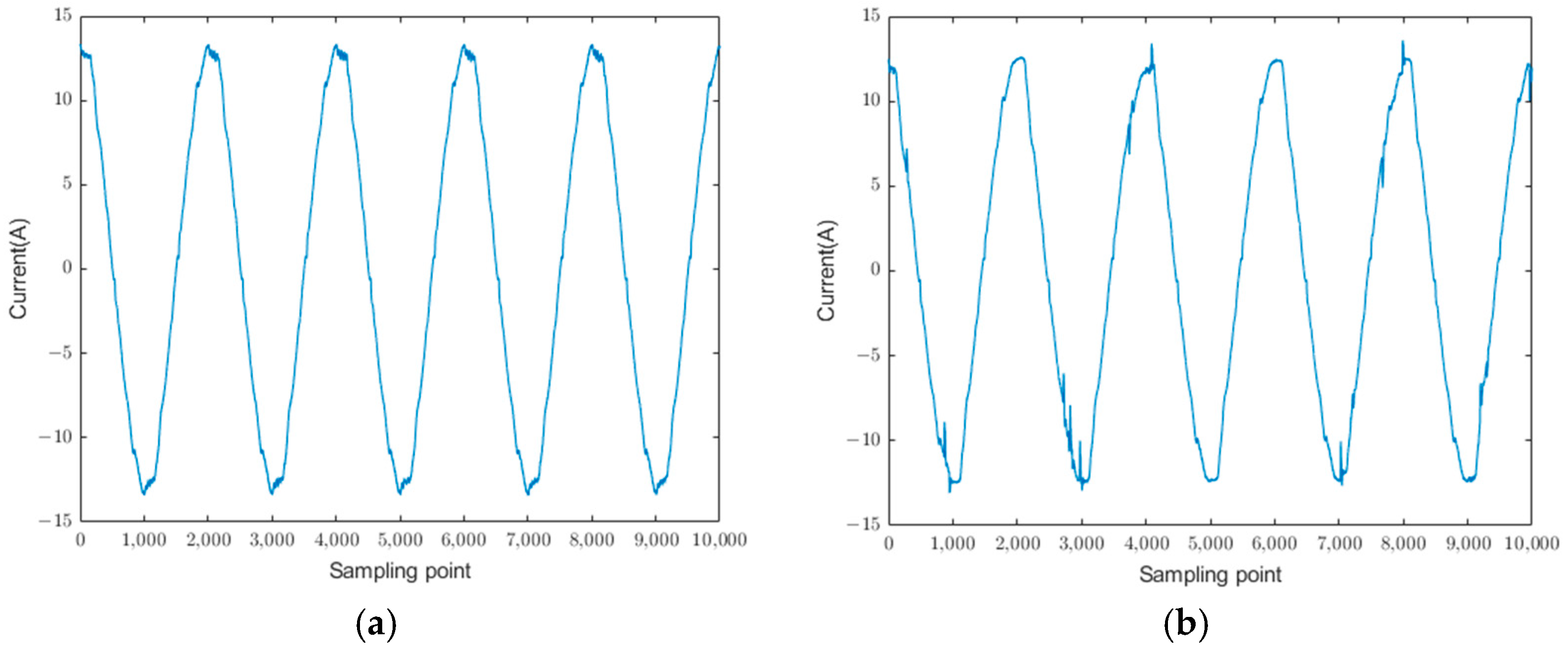
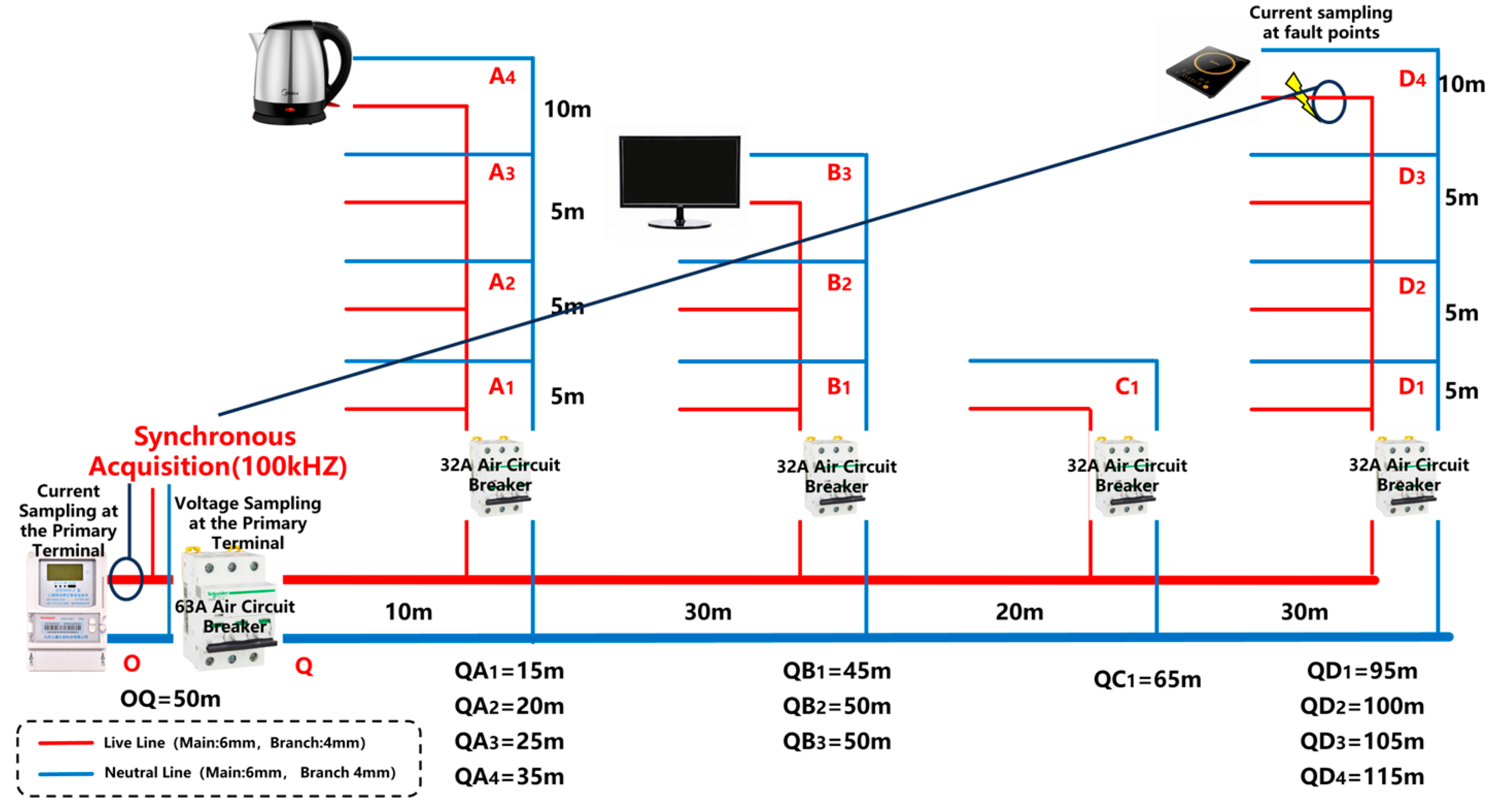
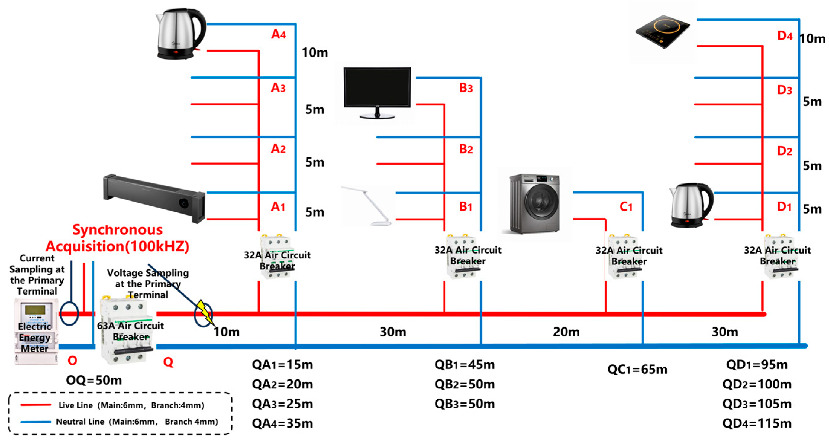
  • A true-to-scale low-voltage series arc fault laboratory was established to simulate arc fault scenarios involving various devices, including induction cookers, displays, kettles, heaters, table lamps, rice cookers, and washing machines. This study examined the transmission phenomena and attenuation characteristics of arc fault features over long-distance (165 m) power lines. Comparative analyses were conducted between normal operating conditions and arc fault scenarios across different device types to comprehensively understand the characteristics of arc faults.
  • This study introduced an AHA multi-risk factor framework, comprising the abnormal distribution, harmonic energy, and abnormal pulse risk factors. By leveraging distribution characteristics, harmonic amplitude energy, and abnormal pulse features, the framework effectively extracts arc fault features while accounting for equipment operation, signal coupling, and signal superposition, ensuring robust and accurate detection.
  • To enhance detection performance and balance the influence of different risk factors, a Knowledge Entropy (KE) weighting allocation method was developed. This innovative approach integrates expert knowledge and information entropy to effectively estimate the relative importance of the proposed risk factors, thereby optimizing the model’s performance.
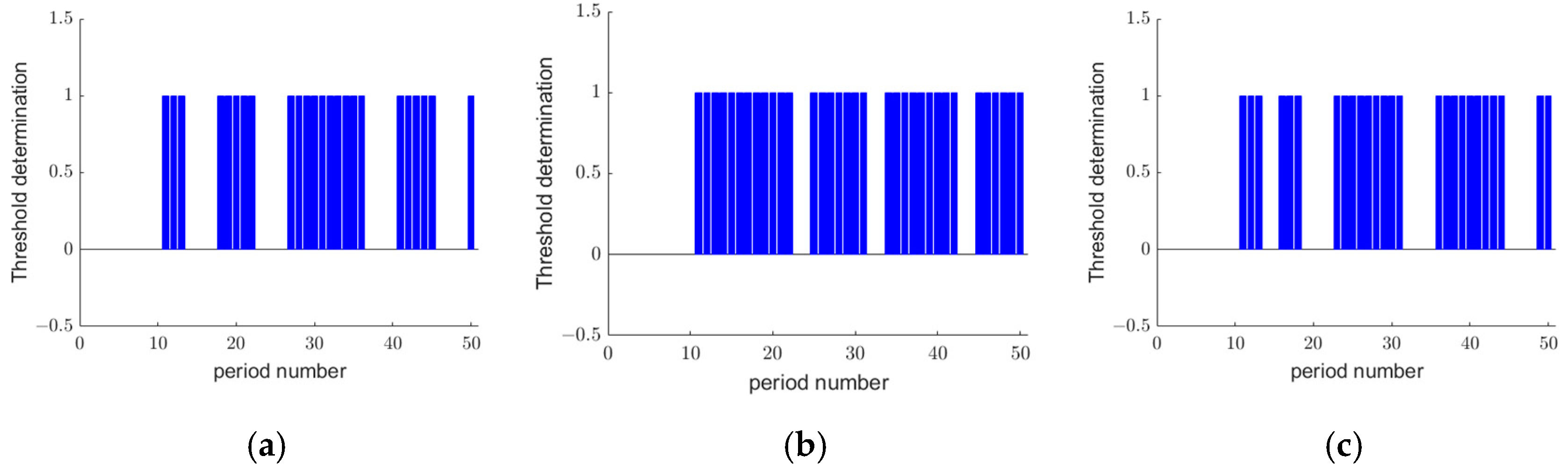
Extensive experiments were conducted under three scenarios: single-appliance arc faults, arc faults with appliance aliasing, and arc faults on public branch circuits. The results demonstrate that the proposed AHA-KE model not only achieves exceptional arc fault detection accuracy but also offers significant advantages in computational efficiency, making it suitable for practical deployment.
The subsequent sections of this study are organized as follows: Section 2 explores the propagation characteristics of arcs in power lines, focusing on their energy properties and time–frequency domain attenuation behaviors. Section 3 introduces the arc fault detection model developed using the AHA-KE methodology. Section 4 details the experimental setup and provides a comparative analysis of the experimental results. Finally, Section 5 summarizes the key findings and contributions of this research.

2. Analysis of Arc Characteristics

2.1. Analysis of Arc Fault Types

The primary causes of arc faults, particularly in urban settings, include the aging of power lines due to prolonged use, increased circuit resistance from damaged insulators, and abnormal electricity usage behaviors. Abnormal usage behaviors often involve operating multiple high-power devices or employing unauthorized temporary wiring. These faults exhibit a high degree of randomness, making it challenging for socket-based fault detection devices to comprehensively identify faults within the circuit.
From the perspective of the user’s power entry points, arc faults in urban residential settings can be classified into three categories based on their occurrence scenarios: single-device arc faults, fault signal coupling, and faults in public branches.
  • Single-device arc faults are localized to a single device within the circuit, with the fault confined to the device itself.
  • Fault signal coupling occurs when multiple devices operate simultaneously in the circuit, causing overlapping electrical signals. This overlap creates complex background noise, which can obscure the detection of arc faults.
  • Public branch faults arise from damaged wiring or suboptimal circuit design, leading to reduced load capacity and triggering arc faults. These faults pose the highest risk due to their potential to propagate widely across circuits.
The typical circuit length for residential users ranges between 40 m and 200 m. Figure 1 illustrates the waveform of arc current measured directly at the fault point. As shown in Figure 1, the low-frequency characteristics of the arc current are less pronounced. This study focuses on retaining the frequency range of 10 kHz to 30 kHz to preserve more current-related features, enabling a comprehensive analysis of arc current faults within this range.

2.2. Energy Characteristics of Arc Faults

Low-voltage alternating current (AC) arcs are nonlinear and unstable electrical faults commonly occurring between poorly connected conductors in urban residential circuits. The arc formation process is typically divided into three stages: initiation, burning, and extinction. However, from a macroscopic perspective at the power entry point, primary attention is given to the arc burning and restriking phases, with initiation and near-extinction approximated as step-like transitions [25].
Arc burning is sustained if the circuit current supports the arc and the input energy exceeds the arc’s dissipative energy. Arc restriking, in contrast, depends on whether the alternating electric field and energy replenishment near the AC signal’s zero-crossing point are sufficient to re-establish the arc. The energy equation for the arc burning process is expressed as follows:
U a r c m + 2 I a r c 2 m = g 2 ( T ) 2 ( b g 1 ( T ) ) m ,
where U a r c represents the arc voltage, I a r c the arc current, g 1 ( T ) a function of the gas temperature associated with the arc energy input, and g 2 ( T ) a function of the gas temperature associated with heat dissipation, and b is the electrode gap and is a constant. This equation highlights that a stable arc burning system irreversibly dissipates externally supplied electrical energy as thermal energy. According to the principle of minimum arc voltage [26], for a given current, this dissipation process maximizes the release of arc energy.
When an arc is generated, a characteristic fault frequency band emerges within the oscillation region of the arc current. The energy distribution is typically analyzed within this filtered frequency band. Using five cycles as a unit, the total energy of the current in the frequency band is defined as E h i :
E h i = n = 1 N / 2 [ u ( i ) ( n ) ] 2 ,
where i denotes the cycle index, N represents the total number of sampling points, and u ( i ) refers to the sequence obtained after band-pass filtering.

2.3. Time–Frequency Domain Attenuation Characteristics of Arc Faults

It is generally assumed that as arc fault signals propagate through the transmission network, higher frequencies exhibit phase-shift characteristics resembling those of a distortion-free system [27]. However, in urban residential power transmission lines, the presence of numerous devices, such as power strips and sockets, introduces complexities. While these devices typically have low resistance, the effects of resistance (R) and inductance (L) become increasingly significant at higher frequencies due to impedance matching and standing wave phenomena. This mismatch in impedance disrupts the transmission line, leading to the attenuation of arc pulse signals at the fault point. The impedance of the transmission line is expressed as follows:
Z = R + j ω L G + j ω C .
The reflection coefficient is given by the following:
Γ = Z L Z 0 Z L + Z 0 .
In these equations, R represents the circuit resistance, L denotes the inductance, C is the capacitance, G signifies the conductance, Γ represents the reflection coefficient, Z L is the load impedance, and Z 0 denotes the characteristic impedance.
In addition, the skin effect of high-frequency currents significantly contributes to the attenuation of arc faults. In urban residential power transmission lines, the impact of high-frequency signal transmission is often overlooked, despite arc faults predominantly occurring within higher-frequency bands. When the high-frequency components of alternating current flow through a conductor, an alternating magnetic field is generated. This field induces eddy currents within the conductor, which counteract the magnetic field at its center, forcing the current to flow predominantly along the conductor’s surface [28]. The skin depth, which characterizes this phenomenon, is given by the following expression:
δ = ρ π f μ
In this equation, δ represents the skin depth, ρ denotes the resistivity of the conductor, μ signifies the magnetic permeability of the conductor, and f represents the signal frequency. As the skin depth decreases, the equivalent resistance of the conductor increases, further amplifying the attenuation of high-frequency components.

3. Arc Detection Method Considering Multiple Risk Factors

3.1. Current Abnormal Distribution Factor

The Maximum Mean Discrepancy (MMD) is a statistical method used to quantify the difference between two probability distributions [29]. For current signals within a specific frequency band, these signals can be represented as data distributions. Although arc pulses exhibit significant periodicity across different cycles, real-world conditions during each electrode breakdown are unlikely to be identical. Consequently, evaluating abnormalities in the distribution of current signals between adjacent sequences can help assess arc risks. The calculation method for the abnormal distribution difference factor is expressed as follows:
M M D 2 = E x ~ P ( x ) [ f ( x ) ] E y ~ Q ( y ) [ f ( y ) ] 2 .
In this equation, f ( x ) represents the characteristic distribution of the filtered current sequence within the current cycle, f ( y ) represents the characteristic distribution of the sequence from the previous cycle, and E x ~ P ( x ) and E y ~ Q ( y ) are the mathematical expectations within the cycle sequences.
The value of M M D 2 is positively correlated with the degree of difference between two adjacent frequency bands. When the degree of difference exceeds a predefined threshold, it is considered that there may be a risk of arc occurrence in the circuit.

3.2. Harmonic Amplitude Energy Factor

Harmonic energy is commonly used to describe the energy distribution of various harmonic components within a signal or system. The periodic signal x ( t ) of urban residential users can be expressed as a Fourier series:
x t = n = 0 A n cos ( n ω 0 t + φ n ) .
Here, A n represents the amplitude of the n -th harmonic, ω 0 is the angular frequency of the fundamental frequency, ω 0 = 2 π / T , and φ n denotes the phase angle of the n -th harmonic. Substituting the Fourier series representation of x ( t ) into the energy formula, for discrete signals X [ t ] , the harmonic energy can be calculated using the discrete Fourier transform (DFT), defined as follows:
X [ k ] = n = 0 N 1 x [ n ] e j 2 π k n N .
The total harmonic energy is then expressed as the following:
E k = 1 N n = 0 N X [ k ] 2 .
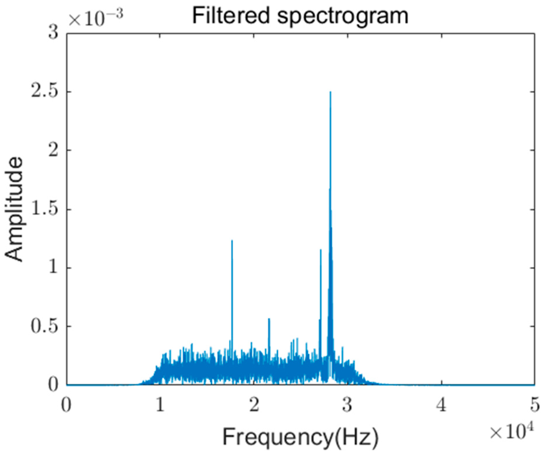
For specific electrical loads, the oscillation region during arc current generation contains fault characteristic frequency bands. The harmonic energy within the fault frequency band is selected as the fault characteristic parameter. Over a period of five cycles, the total harmonic energy is defined as E k , where X [ k ] represents the k t h frequency component of the DFT, and N represents the number of sampling points per cycle. The harmonic amplitude energy evaluation index is given by the following:
E R ( i ) = E k ( i ) E k ( i 1 ) .
Here, i represents the cycle sequence index. When E R ( i ) > 0.7 , it is considered indicative of a higher risk of arc generation in the circuit.

3.3. Pulse Risk Factor

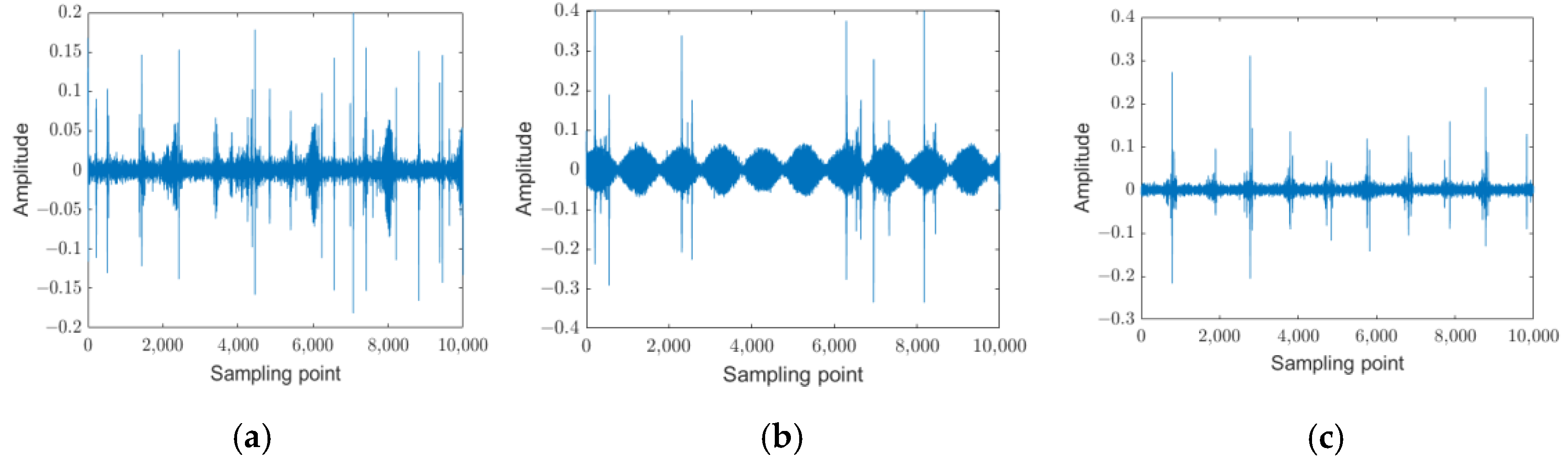
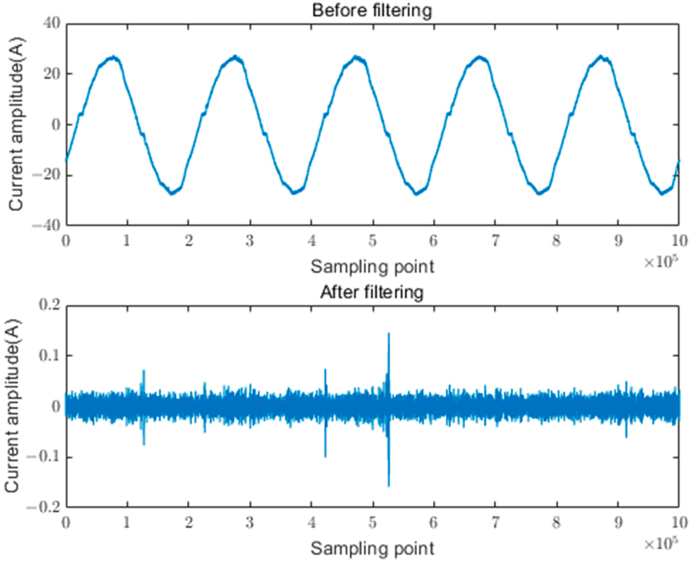
Under normal operating conditions, the amplitude of background noise in equipment typically remains within a relatively narrow range. However, abnormal pulses that emerge following the occurrence of arc faults serve as key indicators for fault detection. To identify these pulses, a density-based clustering method is proposed to isolate abnormal pulses and extract frequency band features, leveraging the characteristic distribution of background noise under normal conditions.
The Density-Based Spatial Clustering of Applications with Noise (DBSCAN) algorithm, which operates based on the concept of density, is employed for this purpose [30]. The core principle of DBSCAN involves defining clusters through distance measurements and density thresholds. For a given dataset D , the algorithm identifies clusters within a region centered on point p with a radius of ε .
N ε ( p ) = { q D | d ( p , q ) ε }
Here, N ε ( p ) represents the neighborhood of point p , encompassing all points whose distance to p does not exceed ε . The density at point p is then evaluated, and p is classified as a core point if N ε M i n P t s holds true, and here, M i n P t s represents the minimum density threshold.
After defining the density of the neighborhood, it is essential to describe the relationships among different points in dataset D . To achieve this, the DBSCAN algorithm introduces the concepts of density reachability and density connectivity. Density reachability is defined as the existence of a path composed solely of core points that connects point p to point q where the path is denoted as { p 1 , p 2 , , p n } . Density connectivity, on the other hand, refers to non-core points within the neighborhood ε that can be connected through a common core point.
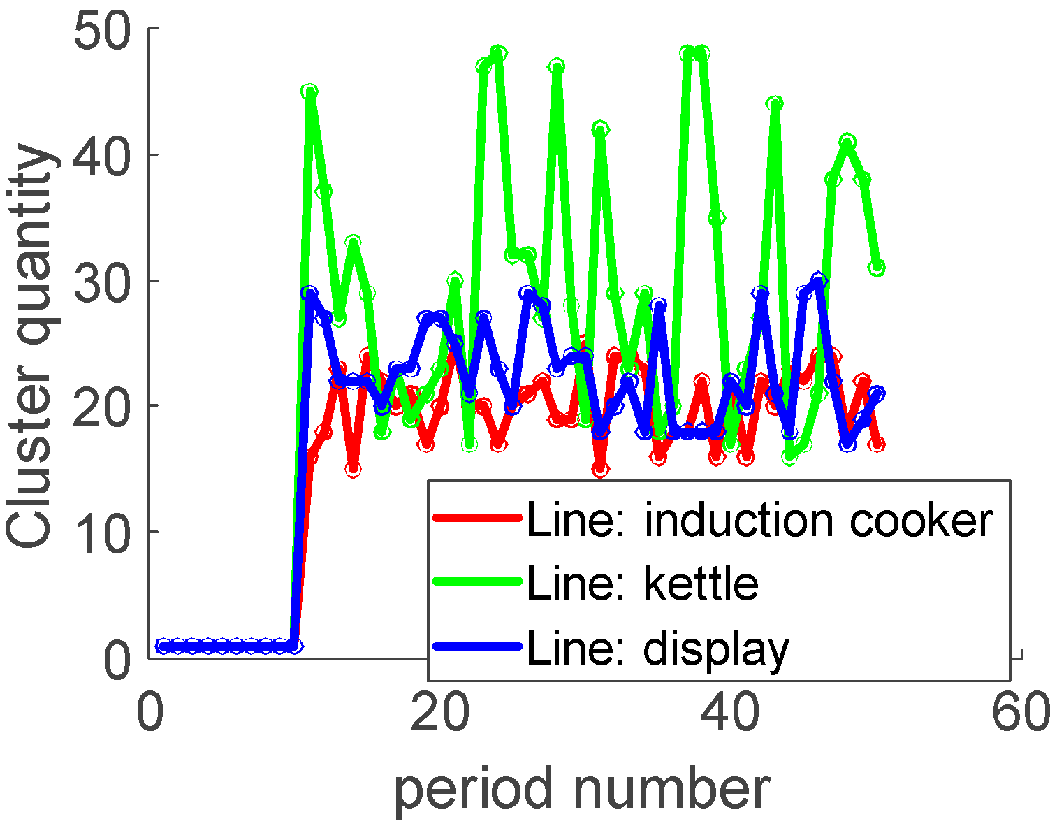
Each time a new core point is identified, a cluster is formed from that point, and the cluster count is incremented by one. Points not included in any cluster are labeled as noise points, recorded as a separate cluster. Once all points are processed, the algorithm outputs the total number of clusters k and the total number of noise points k η . Within a specified frequency band, W C S S is used to evaluate the distribution of pulse points within that band:
W C S S = i = 1 k x C i x μ i 2 .
W C S S is positively correlated with the number of pulse points within the frequency band. A higher number of pulses generated by the arc results in a larger W C S S value, effectively quantifying the activity level within the band.

3.4. Knowledge Entropy-Based Weight Allocation

Different factors often exhibit variations in dimensions and influence scopes, making direct comparison susceptible to the "dominance effect," which can result in the neglect of other factors. To address this issue, designing a rigorous weighting framework is essential for the accurate evaluation of each factor. Subjective weighting, which assigns weights to multiple indicators based on expert judgment or experience, is commonly used to account for the relative importance of each factor.
From the perspective of variation trends among factors, the degree of variation for abnormal pulse risk factors is greater than that of abnormal harmonic amplitude energy factors and abnormal current distribution difference factors. Accordingly, the contribution weights can be estimated as C i = [ 0.4 , 0.3 , 0.3 ] based on their level of importance. However, this estimation relies solely on experience and subjective judgment, which may lead to imprecise weight allocation. Therefore, it is crucial to determine the specific contributions of each indicator and establish corresponding weight coefficients through a more systematic and objective approach.
The entropy weight method is derived from the concept of information entropy in information theory, first proposed by Shannon [31]. Assuming that the probability of an unknown event occurring is p , its total information content is l = log p i . Information entropy represents the mathematical expectation of the information content. Let Y j denote the normalized factors, and Y represent a matrix of m × n :
Y j = y 11 y 12 y 1 m y 21 y 22 y 2 m y n 1 y n 2 y n m
If Y j represents the proportion of the i -th sample in the j -th indicator, denoted as p i j , p i j = y i j i n y i j , then the information entropy Y j is as follows:
E j = 1 ln ( n ) i = 1 n p i j ln ( p i j ) ,
where n represents the number of samples, and E j typically falls within the range E j [ 0 , 1 ] , for j = 1,2 , , m , i = 1,2 , , n . After computing the information entropy using the formula above, the weight of each indicator, W j = 1 E j / m E j , can be determined. M is the last cycle of the arc fault sequence. The entropy-weighted score, λ j , can then be computed using the following formula.
λ j = j = 1 m W j y i j .
To effectively integrate the characteristics of objective data and subjective judgment, the weights derived from the entropy weight method and the expert judgment method are combined in equal proportions, with each method assigned a weight of 50%. The final weight is determined using a weighted average approach. This integration enables the construction of a comprehensive multi-dimensional arc risk factor identification model, whose calculation formula is expressed as follows:
R i s k = λ 1 Y 1 + λ 2 Y 2 + λ 3 Y 3 .
Finally, based on the sensitivity analysis of different risk factors, we obtained the specific weights of each risk factor, as shown in Figure 2. Among the risk factors, the weight of the abnormal pulse risk factor is the largest, followed by that of the harmonic energy and, lastly, that of the abnormal distribution.

4. Experimental Results and Discussion

4.1. Construction of Experimental Platform

The experimental platform is organized as depicted in Figure 3. It comprises four main components: the system power supply, transmission lines, an arc generator, and the experimental load. The system power supply utilizes a standard 220V AC residential power source, with the maximum length of the transmission line set at 165 m. The arc generator, capable of supporting a maximum current of 32 A, simulates series faults using carbon and copper rods within the generator. Current signals are captured at the user meter location using a data acquisition device with a sampling frequency of 100 kHz. The equipment used in the experiment is shown in Table 2.
To validate the proposed detection method, this study evaluates three distinct fault scenarios: (1) single-appliance faults, (2) faults under mixed interference conditions, and (3) faults occurring in the common branch.

4.2. Attenuation Analysis

Table 3 summarizes the attenuation characteristics across various frequency bands. The experimental setup simulates indoor electrical wiring typical of urban residential users, incorporating four branches with multiple connectors and circuit breakers. Fault points were established at distances of 70 m and 165 m along the line for resistive, inductive, and capacitive loads, where series arc operations were conducted. Current variations across different frequency bands were analyzed through synchronized sampling at both the fault points and the meter location.
As shown in the table, signal attenuation becomes more pronounced at higher frequency bands due to the skin effect. The relative attenuation rate varies depending on the specific load, while attenuation values across different frequency bands remain relatively stable. In the 10 kHz to 30 kHz range, the absolute attenuation values are approximately between 6 × 10⁻³ A and 6.5 × 10⁻³ A. For display devices, greater attenuation is observed in the 0–100 Hz frequency band compared to the 100 Hz–1 kHz and 10 kHz–30 kHz bands. This behavior aligns with the skin effect: when an arc is generated, the effective current value in the 0–100 kHz band is only 0.143 A, while attenuation in the 0–100 Hz band consistently ranges between 0.01 A and 0.016 A, leading to a higher attenuation ratio.
For all three types of equipment, attenuation values do not exhibit a clear trend of increasing with distance. In certain frequency bands, smaller attenuation values are observed at longer distances. This phenomenon is attributed to the complex behavior of arc faults during normal equipment operation. High-frequency harmonic components, which are abundant in the frequency spectrum, experience significant coupling losses during propagation and are rapidly absorbed or reflected [32], resulting in considerable randomness in attenuation values.
Figure 4 and Figure 5 illustrate the frequency spectrum for the 10 kHz to 30 kHz band after Fourier transformation. Despite the attenuation of high-frequency features during transmission through conductors, a notable increase in harmonic content is observed following the occurrence of arc faults. Based on this attenuation analysis, it can be concluded that monitoring arc fault signals at the power load entry point of urban residential users is both feasible and effective.

4.3. Risk Assessment of Arc Faults in Single Electrical Appliances

Three representative devices—resistive, capacitive, and inductive loads—were selected as experimental subjects. The devices were placed at a distance of 165 m, where arc fault operations were conducted. An experimental schematic is shown in Figure 6, and the proposed AHA-KE model was employed for fault recognition.
Figure 7 illustrates the Fourier transform spectra of the three devices. The spectrum of the kettle closely resembles that of the display; however, the kettle exhibits significantly higher harmonic content due to its higher rated power, making it more prone to fault breakdowns. Conversely, the display shows slightly higher amplitudes at specific frequencies compared to the kettle. As an inductive device, the induction cooker demonstrates unique characteristics. During arc faults, the device’s inductive properties maintain the current flow, generating a strong counter-electromotive force and high-frequency transient signals. Consequently, the induction cooker spectrum displays higher-frequency components compared to capacitive devices, where this effect is significantly weaker.
Figure 8a shows variations in harmonic amplitude energy before and after arc faults. The kettle and display demonstrate comparable harmonic amplitude energy, while the induction cooker exhibits substantially higher values. Figure 8b introduces an innovative approach to characterizing arc faults using data distribution features. Tighter data distributions correspond to smaller values, whereas larger variations indicate higher values. Although MMD distributions differ slightly during normal operation, they converge to a similar range after arc faults.
The DBSCAN algorithm was further employed to evaluate abnormal pulse risks in circuits. Figure 1 presents the fault-filtered waveforms of the three device types. Figure 9a illustrates the filtered waveform of the kettle during a fault, showing numerous pulses with random amplitudes below 0.2, potentially influenced by arc length. Figure 9b depicts the induction cooker waveform, where fault conditions generate intense pulse currents with amplitudes peaking at 0.4. Figure 9c shows the display’s periodic pulse patterns, attributed to its non-sinusoidal working current and arc faults occurring during switching states.
As shown in Figure 10, fault pulse points are clearly identifiable within the monitored frequency bands. Figure 11 provides a statistical analysis of noise points across different periods. Based on the analysis, arc fault risks are categorized using a three-tier classification system:
  • Low-risk zone (A = 0–2.7): Indicates a low likelihood of arc faults.
  • Medium-risk zone (A = 2.7–5.9): Suggests localized arc faults caused by poor wiring at device terminals.
  • High-risk zone (A > 5.9): Indicates severe arc faults in shared branch circuits with high fire hazard potential.
R i s k _ i n d e x = 0 R i s k [ 0,2.7 ] 1 R i s k ( 2.7,5.9 ] 2 R i s k ( 5.9 , ]
The evaluation results for different devices are summarized in Figure 12. In a 50-cycle experiment, the first 25 cycles represented normal conditions, while the latter 25 cycles included arc faults. The proposed detection model successfully identified arc faults within the first cycle after their occurrence for all three devices.
To comprehensively evaluate the performance of the model, comparisons were made with existing methods, including the current difference algorithm, half-cycle energy detection, Pearson autocorrelation, the Salp Swarm Algorithm with sample entropy (Sam-SSA) [33], the support vector machine based on wavelet transform (Wavelet-SVM) [32], and the Radial Basis Function network based on sample entropy (Sam-RBF) [32]. Table 4 summarizes the experimental results, comparing the model’s performance in terms of average accuracy, latency, and false detection rate. The current difference algorithm and Pearson autocorrelation demonstrated the poorest performance, with the latter producing false detections for the induction cooker due to its periodic noise under normal conditions (Figure 13). In contrast, the proposed AHA-KE model achieved the highest accuracy and the shortest detection time, demonstrating its superior performance in arc fault detection.

4.4. Identification of Arc Faults Under Signal Coupling Conditions

In urban residential electrical circuits, arc faults are often superimposed with signals generated by other normally operating devices. A schematic diagram of the experimental setup is shown in Figure 14. This section evaluates the effectiveness of the proposed AHA-KE model under conditions of arc fault superposition. The superposition scenarios used in this study are summarized in Table 5, with total power settings of 4050 W and 2680 W, respectively, to analyze the impact of background loads on the evaluation model. As shown in Figure 15, compared to Figure 9, the current characteristics within the frequency band under aliasing conditions are smaller than those observed with a single device. This is because the induction cooker, as a typical inductive device, is able to absorb some of the pulses [34].
The experimental results, presented in Table 6, demonstrate that the proposed AHA-KE model maintains exceptional detection performance, even under conditions of device noise coupling. In contrast, the detection accuracy of other algorithms declines significantly in such scenarios. This robustness is attributed to the carefully designed arc risk factors, which effectively characterize arc fault behavior despite the presence of signal coupling and background noise.

4.5. Identification of Arc Faults in Public Branch Circuits

This study further investigates arc faults occurring on public branches, focusing on the characteristics of arcs when multiple devices are connected in series. Four types of devices were placed 165 m from the monitoring point, connected in series, and arc fault operations were conducted on the public branch. A schematic diagram of the experimental setup is shown in Figure 16, while the device types and total power settings are detailed in Table 7. For safety considerations, the maximum total power was limited to 4880 W.
Experimental observations reveal that when the total load is set to 2880 W, the arc fault behavior is comparable to that observed in individual devices or superposition scenarios. However, as the total power increases to 4880 W, the arc generated on the public branch burns more intensely. Notably, the fault characteristics in the frequency band are not merely a superposition of individual device arcs. During arc faults, devices such as displays and table lamps remained operational, contributing to significant currents and elevated arc temperatures in the circuit. These conditions led to more sustained electrode breakdown.
Using the proposed AHA-KE model, arc faults on the public branch were successfully detected, with the results depicted in the accompanying figure. Table 8 compares the detection performance of various models, highlighting that the AHA-KE model not only accurately identified arc faults on the public branch but also determined the corresponding risk levels. Additionally, the model successfully detected arc faults within 100 ms, demonstrating its rapid response capabilities. These findings conclusively validate the effectiveness and robustness of the AHA-KE model in complex scenarios.

5. Conclusions

This paper introduces AHA-KE, a robust method for detecting arc faults in complex environments. By leveraging the current anomaly distribution factor, harmonic amplitude energy factor, and pulse risk factor, alongside a unique weight allocation model, AHA-KE enhances feature extraction and detection accuracy. The experimental results demonstrate its effectiveness across diverse scenarios, including single-appliance faults, fault superposition, and public branch faults, with consistent performance and rapid detection within 100ms. The model’s ability to maintain high accuracy under complex conditions, such as noise coupling and high-power loads, validates its potential for practical deployment in urban residential electrical systems. Considering the three scenarios, the method proposed in this paper can detect faults within 0.14 s after the occurrence of the arc, with an average latency of 0.134 s. Considering the impact of severe EMI environments on the model is a good suggestion, as there are many EMI environments in industrial sites. However, the model proposed in this paper focuses on household appliances in low-voltage AC scenarios, where severe EMI environments are rarely encountered. In future research on arc monitoring for industrial equipment, we will pay particular attention to the impact of EMI on model performance. Future work will focus on refining feature extraction methods, enhancing algorithm robustness, and adapting to evolving grid conditions, ensuring improved safety and reliability in electrical systems.

Author Contributions

Conceptualization, P.H. and Z.K.; methodology, P.H. and Z.K.; validation, P.H.; formal analysis, P.H.; investigation, P.H.; resources, P.H. and L.D.; writing—original draft preparation, P.H.; writing—review and editing, T.H. and L.D.; visualization, P.H.; supervision, Z.K. and T.H.; project administration, Z.K.; funding acquisition, Z.K. and L.D. All authors have read and agreed to the published version of the manuscript.

Funding

The work of Li Ding was supported in part by the grant from Smart Grid National Science and Technology Major Project (No. 2024ZD0802100). The work of Zhengmin Kong was supported in part by the grant from National Natural Science Foundation of China (No. 62173256). The work of Li Ding was supported in part by the grant from National Natural Science Foundation of China (No. 62373290).

Data Availability Statement

All data included in this study are available upon request by contacting the corresponding author.

Conflicts of Interest

The authors declare no conflict of interest.

References

  1. Gregory, G.D.; Scott, G.W. The arc-fault circuit interrupter an emerging product. In Proceedings of the Industrial and Commercial Power Systems Technical Conference, Conference Record, Papers Presented at the 1998 Annual Meeting, Edmonton, AB, Canada, 3–8 May 1998; pp. 48–55. [Google Scholar]
  2. Saleh, S.A.; Valdes, M.E.; Mardegan, C.S.; Alsayid, B. The state-of-the-art methods for digital detection and identification of arcing current faults. IEEE Trans. Ind. Appl. 2019, 55, 4536–4550. [Google Scholar] [CrossRef]
  3. Martel, J.; Anheuser, M.; Berger, F. A study of arcing fault in the low-voltage electrical installation. In Proceedings of the 56th IEEE Holm Conference on Electrical Contacts, Charleston, SC, USA, 4–7 October 2010; pp. 1–11. [Google Scholar]
  4. IEC62606; General Requirements for Arc Fault Detection Devices. IEC: Geneva, Switzerland, 2013.
  5. Qin, D.; Zhang, Z.; Zhang, D.; Xu, Y.; Wan, C.; Lakshmi, R.; Tohid, S.; Dong, D.; Cao, Y. Oscillation Issue and Solution for Solid-State Circuit Breaker Using High Power IGBT Module. IEEE Trans. Ind. Appl. 2024, 60, 765–772. [Google Scholar] [CrossRef]
  6. Dam, S.K.; Yang, C.H.; Dong, Z.; Qin, D.; Chen, R.; Wang, F.; Bai, H.; Zhang, Z. Module Development for a High Specific Power Density High-Efficiency Cryogenic Solid-State Circuit Breaker for Electrified Aircraft Propulsion. IEEE Trans. Power Electron. 2024, 39, 13234–13247. [Google Scholar] [CrossRef]
  7. Miao, W.; Wang, Z.; Wang, F.; Lam, K.H.; Pong, P.W.T. Multicharacteristics Arc Model and Autocorrelation-Algorithm Based Arc Fault Detector for DC Microgrid. IEEE Trans. Ind. Electron. 2023, 70, 4875–4886. [Google Scholar] [CrossRef]
  8. Qu, N.; Wang, J.; Liu, J. An arc fault detection method based on current amplitude spectrum and sparse representation. IEEE Trans. Instrum. Meas. 2019, 68, 3785–3792. [Google Scholar] [CrossRef]
  9. Zhang, Z.; Nie, Y.; Lee, W.J. Approach of voltage characteristics modeling for medium-low-voltage arc fault in short gaps. IEEE Trans. Ind. Appl. 2019, 55, 2281–2289. [Google Scholar] [CrossRef]
  10. Sritrai, E.; Kittiratsatcha, S.; Polmai, S. Low voltage series arc fault detection using Rogowski coil. In Proceedings of the 2018 International Conference on Engineering, Applied Sciences, and Technology (ICEAST), Phuket, Thailand, 4–7 July 2018; pp. 1–4. [Google Scholar]
  11. Liu, Y.; Guo, F.; Wang, Z.; Chen, C.; Li, Y. Research on the spectral characteristics of series arc fault based on information entropy. Trans. China Electrotech. Soc. 2015, 30, 488–495. [Google Scholar]
  12. Kim, S.; Lee, E.; Je, D.; Seo, S. A physical and logical security framework for multilevel AFCI systems in smart grid. IEEE Trans. Smart Grid 2011, 2, 496–506. [Google Scholar] [CrossRef]
  13. Mukherjee, A.; Routray, A.; Samanta, A.K. Method for online detection of arcing in low-voltage distribution systems. IEEE Trans. Power Deliv. 2017, 32, 1244–1252. [Google Scholar] [CrossRef]
  14. Kim, C.J. Electromagnetic radiation behavior of low-voltage arcing fault. IEEE Trans. Power Deliv. 2009, 24, 416–423. [Google Scholar] [CrossRef]
  15. Miao, W.; Xu, Q.; Lam, K.H.; Pong, P.W.; Poor, H.V. DC arc-fault detection based on empirical mode decomposition of arc signatures and support vector machine. IEEE Sens. J. 2021, 21, 7024–7033. [Google Scholar] [CrossRef]
  16. Yang, K.; Chu, R.; Zhang, R.; Xiao, J.; Tu, R. A novel methodology for series arc fault detection by temporal domain visualization and convolutional neural network. Sensors 2020, 20, 162. [Google Scholar] [CrossRef]
  17. Zhang, T.; Zhang, R.; Wang, H.; Tu, R.; Yang, K. Series AC arc fault diagnosis based on data enhancement and adaptive asymmetric convolutional neural network. IEEE Sens. J. 2021, 21, 20665–20673. [Google Scholar] [CrossRef]
  18. Yu, Q.; Huang, G.; Yang, Y. Low voltage AC series arc fault detection method based on parallel deep convolutional neural network. IOP Conf. Ser. Mater. Sci. Eng. 2019, 490, 072020. [Google Scholar] [CrossRef]
  19. Yu, Q.; Lu, W.; Yang, Y. Multi-branch series fault arc detection method based on deep long short-term memory network. J. Comput. Appl. 2021, 41, 321–326. [Google Scholar]
  20. Chu, R.; Zhang, R.; Huang, Q.; Yang, K. TDV-LSTM: A new methodology for series arc fault detection in low power AC systems. In Proceedings of the 2020 IEEE Sustainable Power and Energy Conference (iSPEC), Chengdu, China, 23–25 November 2020; pp. 2319–2324. [Google Scholar]
  21. Siegel, J.E.; Pratt, S.; Sun, Y.; Sarma, S.E. Real-time deep neural networks for internet-enabled arc-fault detection. Eng. Appl. Artif. Intell. 2018, 74, 35–42. [Google Scholar] [CrossRef]
  22. Wang, Y.; Zhang, F.; Zhang, X.; Zhang, S. Series ac arc fault detection method based on hybrid time and frequency analysis and fully connected neural network. IEEE Trans. Ind. Inform. 2019, 15, 210–6219. [Google Scholar] [CrossRef]
  23. Chu, R.; Zhang, R.; Yang, K.; Xiao, J. A series arc fault detection method based on multi-layer convolutional neural network. Power Syst. Technol. 2020, 44, 4792–4798. [Google Scholar]
  24. Wang, Y.; Hou, L.; Paul, K.C.; Ban, Y.; Chen, C.; Zhao, T. ArcNet: Series AC arc fault detection based on raw current and convolutional neural network. IEEE Trans. Ind. Inform. 2022, 18, 77–86. [Google Scholar] [CrossRef]
  25. Zeller, P.; Schoepf, T.J. Advanced Arc Model for Computation of Low Current Arc Characteristics. In Proceedings of the 2010 Proceedings of the 56th IEEE Holm Conference on Electrical Contacts, Charleston, SC, USA, 4–7 October 2010; pp. 1–8. [Google Scholar] [CrossRef]
  26. Zhang, H.; Su, X.; Long, C.; Ren, J. High Impedance Arc Fault Detection in Distribution Networks Based on Instantaneous Parameters Characteristic in Time-frequency Domain. In Proceedings of the 2023 Panda Forum on Power and Energy (PandaFPE), Chengdu, China, 27–30 April 2023; pp. 555–561. [Google Scholar] [CrossRef]
  27. Yuan, X.; Lei, B.; Li, Z.; Qi, W. Skin Effect Analysis for Pulse Current in the PEA Based on Frequency Domain Method. IEEE Trans. Plasma Sci. 2015, 43, 1611–1616. [Google Scholar] [CrossRef]
  28. Kerouh, F.; Serir, A. An adaptive deblurring method based on a Multiplicative Multiresolution Decomposition (MMD). In Proceedings of the European Workshop on Visual Information Processing (EUVIP), Paris, France, 10–12 June 2013; pp. 88–93. [Google Scholar]
  29. Meng’Ao, L.; Dongxue, M.; Songyuan, G.; Shufen, L. Research and Improvement of DBSCAN Cluster Algorithm. In Proceedings of the 2015 7th International Conference on Information Technology in Medicine and Education (ITME), Huangshan, China, 13–15 November 2015; pp. 537–540. [Google Scholar] [CrossRef]
  30. Qi, J.; Liu, J.; Liu, Z.; Wang, K. Evaluation Method of Power Channel Operation Quality Based on Entropy Weight Method. In Proceedings of the 2023 3rd International Conference on New Energy and Power Engineering (ICNEPE), Huzhou, China, 24–26 November 2023; pp. 1014–1017. [Google Scholar] [CrossRef]
  31. Fu, H.; Xu, Z. Feedback Oscillation Circuits for High-Frequency Surface Acoustic Wave Device. In Proceedings of the 2024 6th International Conference on Electronic Engineering and Informatics (EEI), Chongqing, China, 8–30 June 2024; pp. 222–225. [Google Scholar] [CrossRef]
  32. Da Rocha, G.S.; Pulz, L.T.C.; Gazzana, D.S. Serial Arc Fault Detection Through Wavelet Transform and Support Vector Machine. In Proceedings of the 2021 IEEE International Conference on Environment and Electrical Engineering and 2021 IEEE Industrial and Commercial Power Systems Europe (EEEIC/I&CPS Europe), Bari, Italy, 7–10 September 2021; pp. 1–5. [Google Scholar] [CrossRef]
  33. Li, B.; Wu, J. Low-Voltage Arc Fault Identification Using a Hybrid Method Based on Improved Salp Swarm Algorithm–Variational Mode Decomposition–Random Forest. IEEE Access 2024, 12, 5410–15418. [Google Scholar] [CrossRef]
  34. Chen, S.; Liu, Y.; Mi, J.; Wang, Z.; Gao, P.; Li, X. Adaptive Detection Method for Arc Faults in Low Voltage Power Supply Systems. In Proceedings of the 2024 IEEE 69th Holm Conference on Electrical Contacts (HOLM), Annapolis, MD, USA, 6–10 October 2024; pp. 1–6. [Google Scholar] [CrossRef]
Figure 1. Comparison of current waveforms before and after fault. (a) Normal state. (b) Arc occurrence.
Electronics 14 00708 g001
Figure 2. Weights of different factors.
Electronics 14 00708 g002
Figure 3. Arc monitoring experiment platform.
Electronics 14 00708 g003
Figure 4. No arc fault harmonic components.
Electronics 14 00708 g004
Figure 5. Arc fault harmonic components.
Electronics 14 00708 g005
Figure 6. Schematic diagram of single-appliance fault experiment.
Electronics 14 00708 g006
Figure 7. Spectral graphs of arc faults in different appliances. (a) Kettle. (b) Induction cooker. (c) Display.
Electronics 14 00708 g007
Figure 8. Risk factor variations before and after arcing. (a) Harmonic amplitude energy. (b) Distribution difference.
Electronics 14 00708 g008
Figure 9. Fault current waveform within frequency band. (a) Kettle. (b) Induction cooker. (c) Display.
Electronics 14 00708 g009
Figure 10. DBSCAN detection of anomalous pulses. (a) Kettle. (b) Induction cooker. (c) Display.
Electronics 14 00708 g010
Figure 11. Number of clusters before and after arcing.
Electronics 14 00708 g011
Figure 12. AHA-KE detection results. (a) Kettle. (b) Induction cooker. (c) Display.
Electronics 14 00708 g012
Figure 13. Background noise from normal device operation.
Electronics 14 00708 g013
Figure 14. Schematic diagram of experiment with fault signal coupled to normal operating device waveforms.
Electronics 14 00708 g014
Figure 15. Current waveform under arc fault conditions.
Electronics 14 00708 g015
Figure 16. Schematic diagram of public branch arc fault experiment.
Electronics 14 00708 g016
Table 1. Comparison of different models.
Arc Detection Model The Extracted FeaturesSuitable for Complex EnvironmentsModel Complexity
Based on Traditional DetectionCurrent- and Voltage-related Characteristics[7,8,9,10,11]NoLow
Other Characteristics[12,13,14]NoLow
Based on Artificial IntelligenceAutomatic Feature Extraction[15,16,17,18,19,20,21,22,23,24][16,18,19,20]High
Table 2. The equipment used in the experiment.
BrandLoadRated Power/W
MR1200Oscilloscope-
ADD-YArc Generation Device-
SUPORKettle1800
MIDEARice Cooker830
HAIERElectric Heating2200
AUXDesk Lamp16
LENOVODisplay50
HAIERWashing Machine300
SUPORInduction Cooker1900
Table 3. Attenuation in different frequency bands of arc faults.
Frequency Band/Attenuation RateKettle (70 m)Kettle (165 m)Induction Cooker (70 m)Induction Cooker (165 m)Display (70 m)Display (165 m)
0–1000.49194%0.24292%0.28868%0.13051%14.5843%11.4386%
100–1k0.57934%0.73119%0.51658%0.51983%0.6837%0.61418%
10k–30k41.0938%44.7151%2.7366%3.182%8.0562%8.3635%
30k–50k81.0304%75.7527%50.5269%83.6254%89.0269%101.3733%
Table 4. Average detection accuracy of different models for three devices.
MethodInduction CookerKettleDisplay
Average AccuracyTime (s)False Positive CountAverage AccuracyTime (s)False Positive CountAverage AccuracyTime(s)False Positive Count
Half-Cycle Energy Detection0.98710.2047 s00.99230.223500.96920.25160
Current Difference Algorithm0.86520.0516 s30.84640.049550.86010.05092
Pearson Autocorrelation Detection0.53450.0497250.87530.047700.87430.04810
Sam-SSA0.96160.196300.99410.212200.97120.19240
Wavelet-SVM0.94500.223100.97020.227500.96070.20750
Sam-RBF0.94170.362800.99100.342200.98410.38470
AHA-KE (ours)0.99470.131900.99350.130600.99840.13340
Table 5. Different coupling scenarios.
LineTotal PowerArc Fault DeviceDevices in ParallelDistance to Monitoring Point
14050 wKettleDisplay, Kettle, Electric Heating165 m
22680 wDisplayInduction Cooker, Kettle, Display165 m
Table 6. Average detection accuracy of different models for two coupling conditions.
MethodLine 1Line 2
Average AccuracyTime (s)False Positive CountAverage AccuracyTime (s)False Positive Count
Half-Cycle Energy Detection0.97960.2028 00.99230.2134 0
Current Difference Algorithm0.70520.0502 120.84640.0560 9
Pearson Autocorrelation Detection0.81530.047300.57530.043350
Sam-SSA0.96500.199400.99270.21070
Wavelet-SVM0.94480.218900.98290.20790
Sam-RBF0.94100.362200.97520.35560
AHA-KE (ours)0.99080.137700.99710.13250
Table 7. Arc faults at different power levels.
LineTotal PowerArc Occurrence LocationDevices in Series
14880 w165 mKettle, Induction Cooker, Display, Rice Cooker, Washing Machine
22800 w165 mInduction Cooker, Display, Rice Cooker, Desk Lamp
Table 8. Average detection accuracy of three models at different power levels.
MethodLine 1Line 2
Average AccuracyTime (s)False Positive CountAverage AccuracyTime (s)False Positive Count
Half-Cycle Energy Detection0.96940.268400.98770.28710
Current Difference Algorithm0.71570.0462120.79640.04999
Pearson Autocorrelation Detection0.51530.0459250.57400.045025
Sam-SSA0.95970.222100.98080.21070
Wavelet-SVM0.94180.237300.98290.24550
Sam-RBF0.94230.371700.97880.35660
AHA-KE (ours)0.98750.133200.98590.13890
Disclaimer/Publisher’s Note: The statements, opinions and data contained in all publications are solely those of the individual author(s) and contributor(s) and not of MDPI and/or the editor(s). MDPI and/or the editor(s) disclaim responsibility for any injury to people or property resulting from any ideas, methods, instructions or products referred to in the content.

