1. Introduction
Autonomous Underwater Vehicles (AUVs) are used for multiple applications, such as monitoring [
1], research [
2], and military tasks [
3]. However, the problem with these kinds of devices is that their autonomy is short. This is mainly due to the need for a light battery so that the vehicle can move without effort. Another relevant inconvenience that AUVs face is related to their charging procedure. Plug-in charging is a difficult task in seawater. This would require human intervention, which is not easy in this environment. Additionally, the need to remove the vehicle from the water requires a greater investment of time, thus increasing the total battery charging time. It can also be affected by corrosion due to the high salinity [
4].
The charging technologies usually proposed in the literature to solve the problem of the system’s autonomy are diverse. Thus, it can be found battery swapping [
5], solar charging [
6], or specific techniques that do not require the use of cables in order to charge the vehicle’s battery [
7], such as docking techniques. However, it can be interesting to increase the analysis of the AUV charging technologies, following the actual trend of the common EV. In this case, the aim is to determine if the inductive-resonant technology, which is the most used wireless technology in EV [
8], is appropriate for these applications and also to find the optimal solution for its adaptation to this environment. Wireless charging can prevent the vehicle from having to leave the water to perform the charging process, as a charging point could be installed at the location where the seabed observation is taking place. This saves both time and energy, as the device would not need to reserve some of the energy provided by the battery to make the displacement between the point under study and the location of the conductive charger.
Most studies related to inductive-resonant chargers are based on the power transmission through the air. The specific solutions found for underwater vehicles are focused on a particular model of vehicle and the support for rotational misalignment, typical in this environment, as can be seen from the following contributions. In [
9], a free-rotation Wireless Power Transfer (WPT) system is proposed following the structure of two decoupled transmitters and a segmented solenoid receiver. Similarly, with a study focused on the rotation misalignment, in [
10] a U-shaped bipolar coil transmitter, together with an arc-shaped unipolar receiver, is proposed, achieving a high misalignment tolerance. With the same objective, a novel structure is proposed in [
11] with the consideration of a
folded spatial unipolar coil, which is designed for a specific model of AUV. Other solutions, such as [
12] or [
13], optimise the coils with the main objective of suppressing possible power fluctuations due to misalignment between the coils. Authors in [
14] propose a novel structure where the transmission coils are vertically arranged, generating a toroidal magnetic field, while the receiving coils are embedded into the tail vanes, between the transmission coils. As it can be deduced, the main objective of most solutions in literature is to solve the misalignment issue, but not the analysis of the effects of seawater conductivity on the charging process. In fact, these effects are often omitted, on the assumption that the behaviour will be similar even though the environment is different.
However, this approach is not accurate. In seawater environment, it should be considered, at least, that the seawater conductivity is higher than the air conductivity [
15], which will have different consequences. For example, the generated eddy currents are higher in seawater [
16], and, in this environment, it is more probable the appearance of a parasitic capacitance between the power coils [
17] due to salinity. This parasitic capacitance also has a direct relation to the coil characteristics, such as size and geometry, the distance between the coupled coils [
18], as well as the use of multilayer coils [
19]. This parasitic capacitance can have effects on the system variables, like the system voltage and current. It also modifies the impedances of the circuits, leading to a resonant frequency that differs from the one computed when this element is not considered. It is worth noting that the WPT systems are usually designed to maximise the efficiency at the resonant frequency, which is set as the operational frequency. Working at different frequencies leads to a loss of efficiency, mainly due to uncompensated reactive power. Considering the parasitic capacitances in the design process implies analysing a particular electrical model for underwater applications. In fact, the electrical model of the coupled coils is modified since it should be considered an extra element connected to the power coils (emulating the parasitic capacitance). This extra element will change the resonance point of the system if it is not considered as a previous step to the design, which leads to a complex control to change the working frequency. As can be deduced, the consideration of the parasitic capacitance makes the design process less simple than in the case of the air environment. However, few solutions in the literature consider their effects. In [
17], the existence of parasitic capacitances is considered for the design of coils, assuming their appearance between the pair of coupled coils, but considering their value to regulate the operating frequency of the system. In [
20], inter-turn parasitic capacitance is analysed, considering its value to calculate the coupled inductors of the power channel without considering the parasitic capacitance between coils. These are solutions that address the effects of the parasitic capacitance between coils, due to the conductivity of seawater. As it can be deduced, the contributions related to this subject are scarce, which does not allow reaching a high level of knowledge about the effects of this element during the charging process of the inductive charger in this environment. These proposals consider the existence of this phenomenon and how to cope with it, but they do not propose any solution to minimise its value during the design phase of the elements of the underwater WPT system. It is essential to understand the causes of the parasitic capacitance so that its value can be minimised and the system can be designed as an air-based inductive charger, thus simplifying the circuit design. This is one of the main contributions of this paper, as can be observed in
Table 1, where the lack of studies of the effects of parasitic capacitance is clearly visible.
The aim of this contribution is the optimisation of coils and compensation systems to avoid the effects of the parasitic capacitance. In this way, the design process of the wireless charging is simplified and equivalent to an air-based solution. Indeed, the main interest of this optimisation is to obtain a final underwater system that is similar to an air transmission system so that all the control techniques that have been extensively tested for the air environment can also be applied to seawater. Specifically, in this work, it is analysed how to address the design and implementation of an underwater inductive wireless charger (UIWC), which is adapted to an underwater camera, as shown in
Figure 1. For our particular application, the design should be performed based on the following requirements:
Charger dimensions. As the underwater camera has reduced dimensions, the inductive charger should fit with dimension requirements in order not to exceed the size of the final device. In this case, the maximum diameter covered by the charger should be lower than 20 cm.
Charging power. The idea of this project is to have the possibility of charging a battery that will be used to feed the device components. This battery is set to have a charging power ranging from 100 W to 240 W, so the inductive charger must operate between these values.
Maximum gap. The distance between coils is expected to be lower than 5 cm, since in this application the charging gap is not a restrictive feature.
These requirements are defined as a guide in the design process, and they could be easily adjusted to other particular applications. Indeed, although this study is carried out in the context of a specific project, it is intended to draw general conclusions that will allow us to establish generic criteria for the design of coils in this kind of device.
In order to establish design criteria, it is important to know the component parts of these systems and decide about their main physical and electrical properties. The main elements that constitute an inductive wireless charger are a pair of coupled coils, the power converters, and the compensation system. Thus, during the design process, the main objective is to optimise the system performance by considering the optimisation of each single element.
Considering the previous requirements and taking into account the issues found in the seawater environment, the main contributions of this paper are described as follows:
The analysis of the effects of the parasitic capacitance on the system variables (voltage and current). This analysis is important to understand the variations in the circuit performance caused by the parasitic capacitance.
The optimisation of the coupled coils to minimise the effects of the parasitic capacitance. The solutions considering the parasitic capacitance are few in the related literature, and there are no studies that minimise the effect of parasitic capacitance via the optimisation in the coil design. Our contribution is of significant interest to researchers, as general design criteria can be established that relate the value of the parasitic capacitance to the characteristics of the pair of coils used. With this information, a pair of coupled coils can be generated with an equivalent electrical model for the sea and the air. In this way, the design and testing of the core of the wireless charging is simplified.
The comparative analysis between SS and LCC–S compensation systems to find the optimal solution in order to maximise the system’s efficiency in the particular scenario of underwater. This comparative analysis is interesting as comparative studies between compensation systems are usually carried out for air power transmissions, not seawater.
This paper is structured as follows.
Section 2 describes the analysis of the specific circuit under study, taking into account the appearance of parasitic capacitance. In
Section 3, the simulation study of the effects of the parasitic capacitance is shown, while
Section 4 considers the efficiency analysis by comparing the proposed solutions and different load resistances. In
Section 5, the design of this specific inductive charger is described, and
Section 6 shows the system validations. This paper ends with the conclusions in
Section 7.
2. Electrical Model of UIWC Charger in Seawater
The proposed inductive wireless charger must operate in seawater, so the effects of this environment should be analysed to derive a precise electrical model. As mentioned in
Section 1, working in seawater may require the inclusion of parasitic capacitances between the power coils [
17]. These parasitic capacitances have a great impact on the resonance conditions.
In order to quantify the effects of the parasitic capacitances, the primary voltage and current will be analysed.
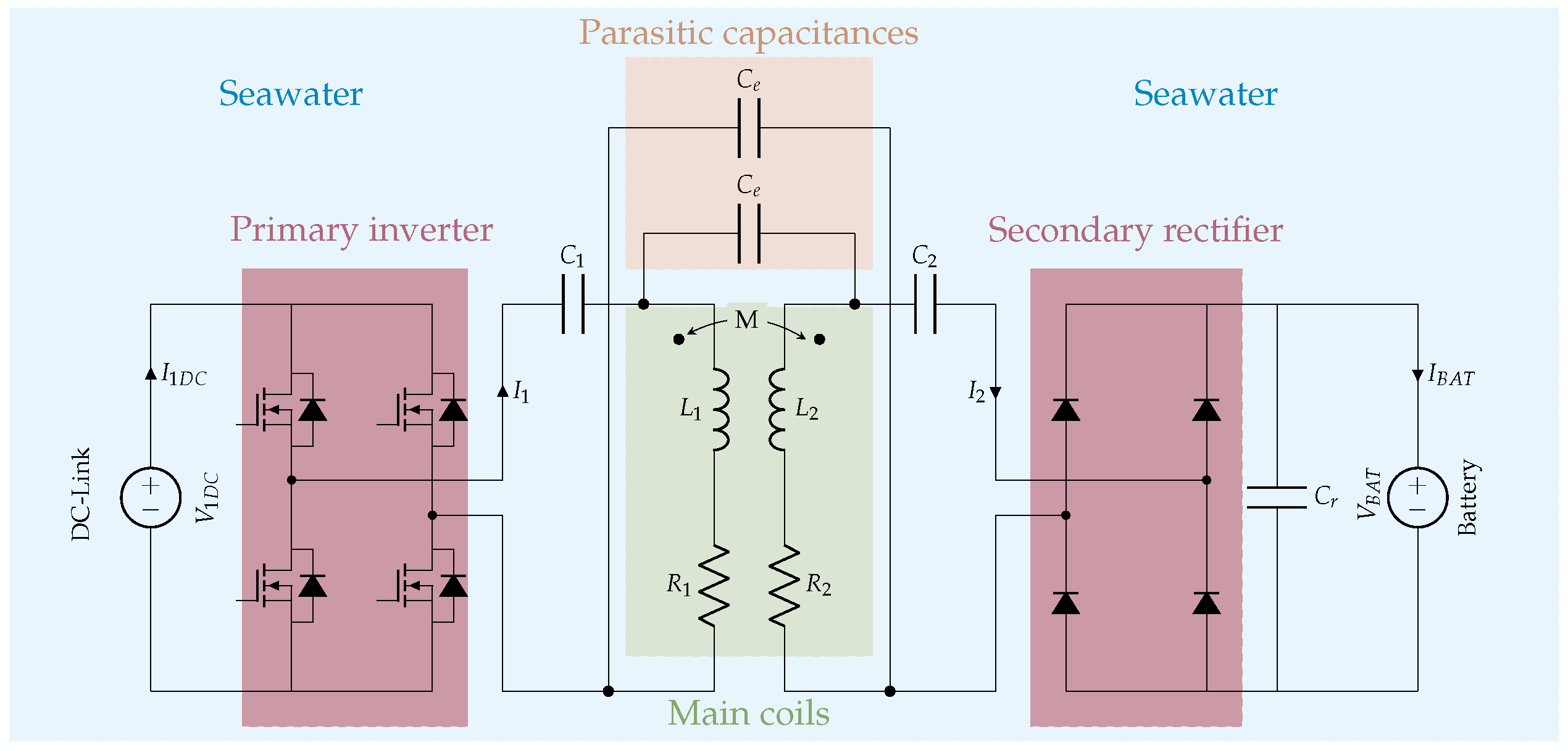
Figure 2 illustrates the scheme of a UIWC. In contrast to the electrical models of typical inductive chargers, a new block is included to consider the parasitic capacitances. Specifically, there are two elements in this new block: two parasitic capacitances, named
, connected in parallel to the main coils. These two parasitic capacitances represent one single capacitor, but the representation is performed in two branches in order to consider the return path. This parasitic capacitance can also be represented by a single capacitor [
21] and by the modification of the main coil and its equivalent resistance [
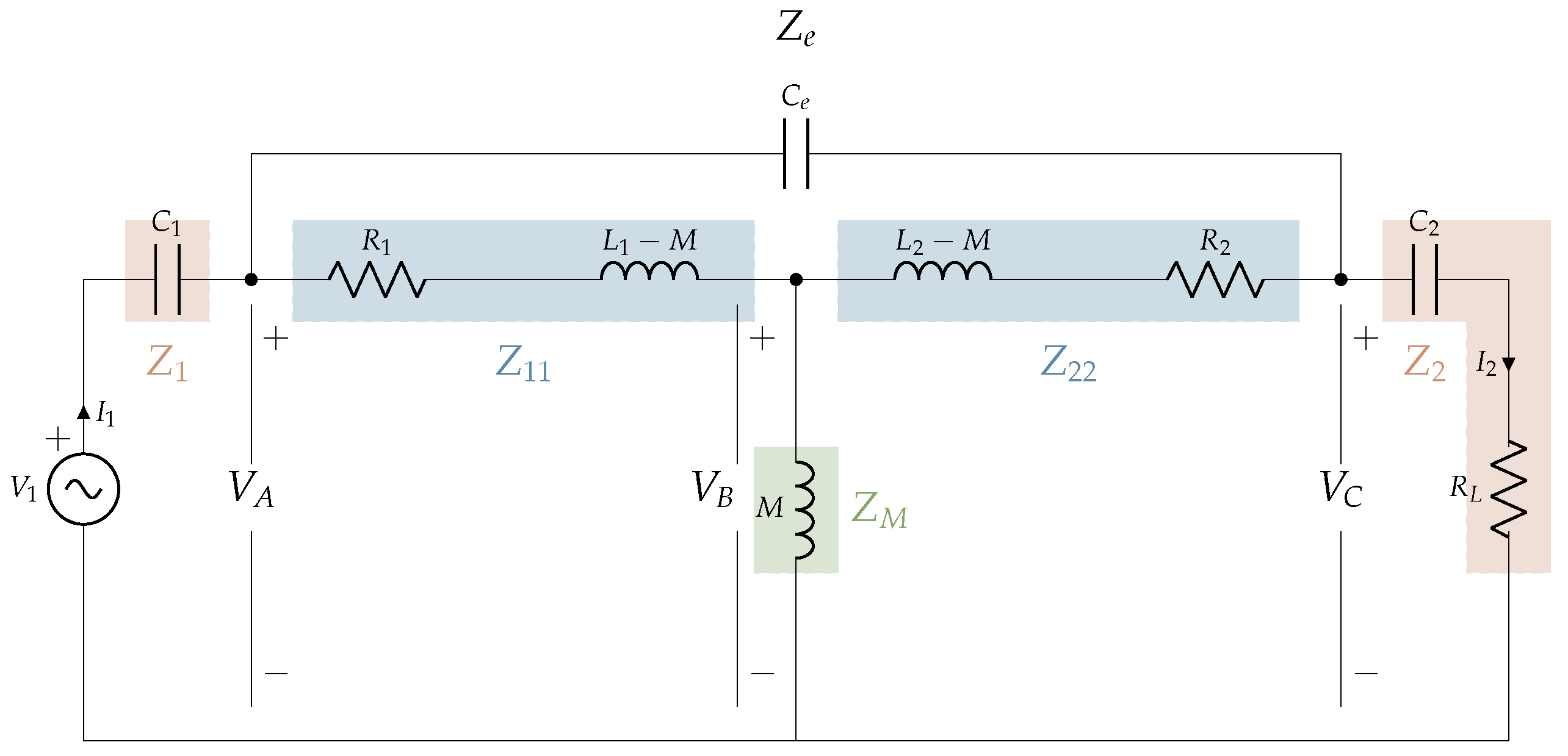
22]. However, the two-capacitor representation is selected due to its extended use. In this electrical model, basic power converters (primary inverter and secondary rectifier) are included in order to give a general idea of the overall performance. However, power converters are simplified in the T-model equivalent scheme, as shown in
Figure 3. It should be noted that, in this case, the parasitic capacitance is represented with a single capacitor (
) between the power coils and the mutual inductance, which is equivalent to the previous representation in
Figure 2.
By using Kirchhoff’s Law, the equations governing the circuit can be achieved. To solve the circuit, impedance parameters are first defined in order to simplify the content of the equations. Equations (
1) and (
2) reflect the impedances of the primary and secondary sides of the compensation systems.
The impedances related to the primary and secondary coils, considering the mutual inductance between coils, are calculated by means of the Equations (
3)–(
5).
where
M is related to the coupling coefficient
k through the expression
.
Finally, the impedance related to the parasitic capacitance is calculated by Equation (
6).
Solving the circuit by applying Kirchhoff’s law, the voltage at points A, B, and C shown in
Figure 3 can be determined. To do so, Equations (
7)–(
9) are calculated.
Once the previous voltages have been calculated, the input voltage (
) and current (
) can be determined taking into account the effect of the parasitic capacitance. These calculations are defined in Equations (
10) and (
11).
The effects that the parasitic capacitance has on the circuit will be studied by analysing the changes in primary voltage and current, since its consideration is strictly related to variations in the system parameters.
3. Analysis of Parasitic Capacitance
The appearance of the parasitic capacitance is a phenomenon caused by the conductivity of seawater, which is higher than freshwater and air [
5], as can be seen in
Table 2. Furthermore, the permittivity data provided in
Table 2 are relevant because the parasitic capacitance depends not only on the conductivity but also on the dielectric properties of the medium. The permittivity affects the ability of the medium to store electric charge, which directly influences the capacitance value.
Additionally, this parasitic capacitance is also affected by the coil geometry, as well as the coil’s size. For this reason, the analysis of the parasitic capacitance should start with the definition of the coupled coils. Due to its good performance, simplicity, and common use in inductive wireless chargers, the circular geometry is the initial proposal of this analysis [
23]. Thus, it can be interesting to find the relation between the coil diameter and the parasitic capacitance value caused by the high conductivity of seawater. To do so, a set of four different coil sizes will be proposed. The definition of the coil size will be determined by the restriction imposed by the underwater device. In the specific application considered in this work, the design cannot exceed 20 cm in order to keep it within the confines of the camera inclosure. In this way, the proposed coil topology is shown in
Figure 4.
In order to find the relation between the coil area and the parasitic capacitance, four solutions have been proposed. Following a circular geometry, cases from N = 15 to N = 30 (being N the number of turns) have been analysed. It should be noted that, initially, an equivalent design is set for the primary and secondary sides in order to simplify the charger design.
The calculation of the parasitic capacitance has been performed by using Ansys Maxwell 2021 software together with the Magnetostatic solver. A block of salt water, with the conductivity and permittivity values given in
Table 2, is placed between the pair of coupled coils. The coils behave like the plates of the parasitic capacitor, and the dielectric medium (salt water) is the environment through which the electric field is transmitted between the plates, simulating the behaviour of a capacitor. Through the excitation of the coils, using a potential difference to activate their operation, a sweep has been carried out considering different coil sizes. With this, it has been possible to identify the value of the equivalent capacitor between these two components via software.
In
Table 3, the results achieved during the simulation of the pair of coupled coils are shown. As can be seen, there is a relation between the value of the parasitic capacitance (
) and the size of the power coils (
and
). In order to better understand this relation,
Figure 5 is included. As deduced from this figure, the parasitic capacitance has an increasing trend with respect to the self-inductance values, where it can be extrapolated that these two variables have a direct proportional relation. For this reason, the coil size should be optimised in order to reduce the value of the parasitic capacitance.
Significant values of parasitic capacitances have an impact on the electrical variables. As modelled in Equations (
10) and (
11), the primary voltage and current have a dependence on the value of the parasitic capacitance. Thus, it is interesting to analyse the electrical effects of the parasitic capacitances in the voltage
and current
for the proposed cases. In this way, a comparative analysis between the circuit considering the parasitic capacitance (associated with an application in seawater) and without considering it (with air-coupled coils) will be performed.
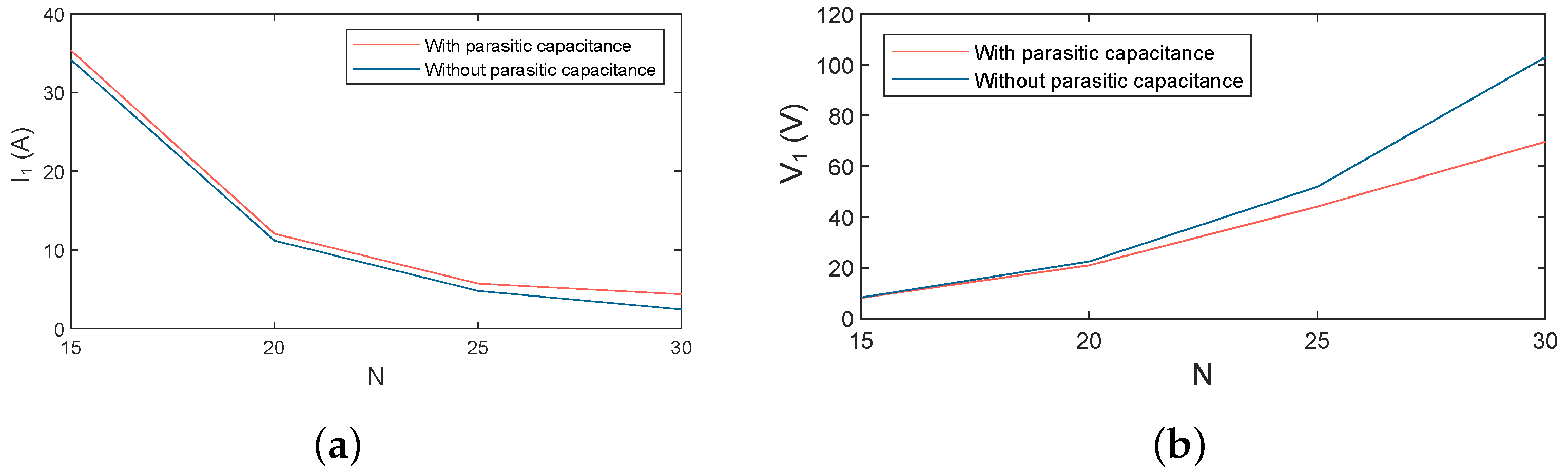
Table 4 shows the final values for the voltage and current for the two configurations. As can be observed from
Figure 6, the higher variations are found in cases of higher value of
N, and, in general, the differences are not very relevant. However, in the case of
N = 30, the voltage variation is 32.94 V, so it can be determined that this case will be neglected since the effects of parasitic capacitance cannot be avoided during the design.
With these results, it can be concluded that the incorporation of the parasitic capacitance in the electrical model can be avoided when there are low variations in the primary current and voltage. In the following sections, the extra analysis needed to finally select the optimal solution will be developed.
4. Analysis of Efficiency
Given the results obtained in the previous section, three possible solutions can be distinguished. The main requirement imposed in this study is that the overall DC efficiency should be at least 80%. It should be mentioned that, at first, the efficiency analysis is related to the SS compensation.
The DC efficiency will be calculated with the relations:
Therefore, the efficiency will be calculated for the three remaining solutions (from to ), as well as different values of load resistance (). The variation of is necessary in order to represent the different battery statuses during the charging process, since the charging parameters are variable (e.g., constant voltage or constant current operating modes).
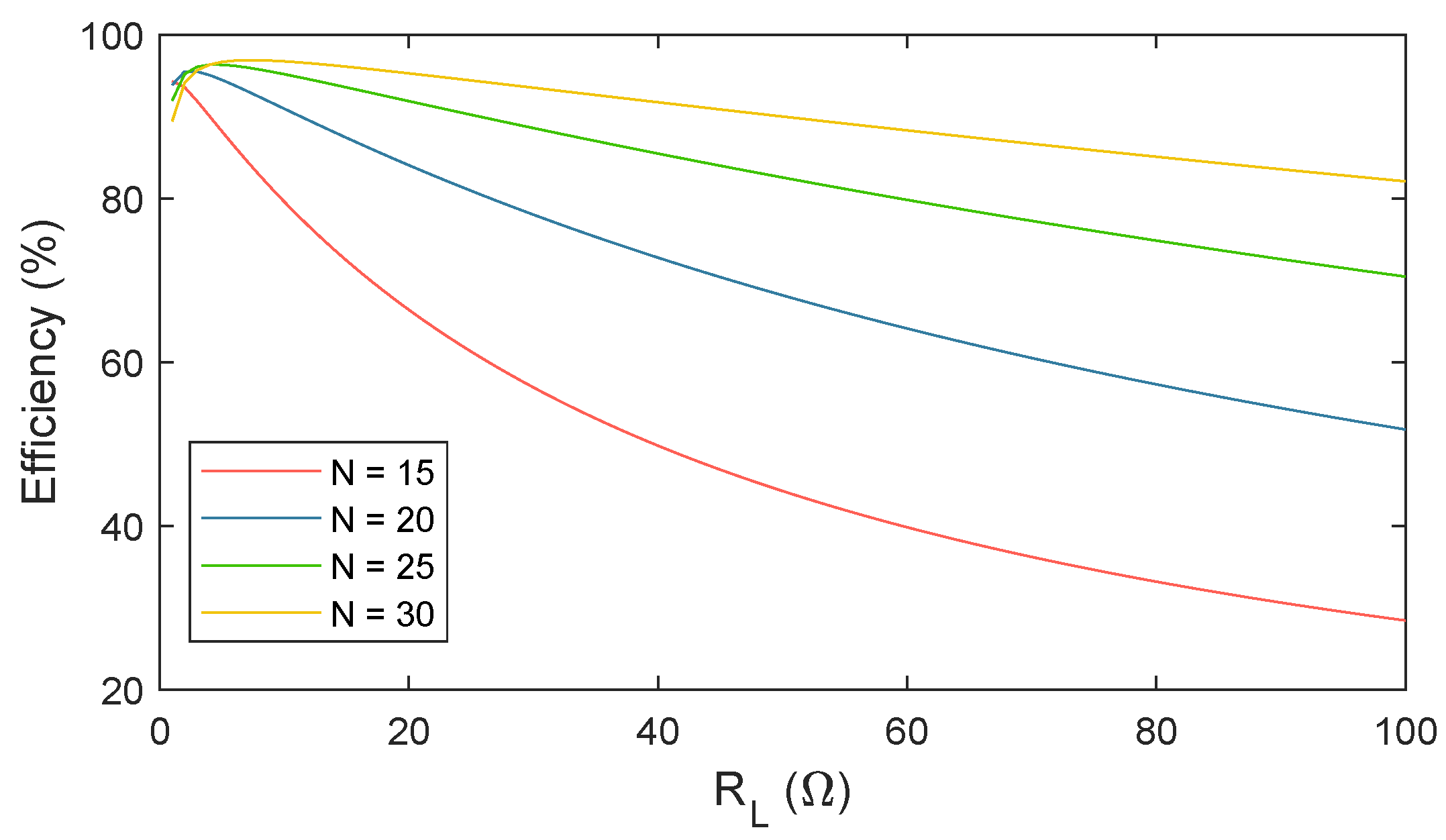
In
Figure 7, the curves that govern the efficiency value along the range of
are represented. This analysis shows that the efficiency of the system is higher as the size of the coil increases. However, a large coil size leads to a rise in parasitic capacitance, which has a greater effect on the model. Therefore, the optimal solution must be found at a point where the efficiency is valid and no relevant differences are found between water and air solutions in order to simplify the study.
The most efficient solution to implement the inductive system in seawater is the one with 30 turns of the coils. However, this solution has been discarded before due to the voltage variation it presents in the electrical analysis with and without a parasitic capacitance. As for the rest of the solutions, the following conclusions are obtained taking into account the efficiency criterion selected for this case study (only efficiencies from 80% to 100% are valid):
N = 25 can be considered as a feasible solution for ranges of from 0 to 80 .
N = 20 can be considered as a feasible solution for ranges of from 0 to 27 .
N = 15 is discarded due to the decrease in efficiency outside the limits imposed.
Thus, at this point, two remaining solutions are feasible for the following analysis:
N = 25 and
N = 20. Considering that the power of the system operation ranges from 100 W to 240 W, and taking into account the relations (
14) and (
15), the load resistance (
) is between 3.03
and 7.29
.
As can be observed in
Figure 7, the efficiency values for
N = 20 and
N = 25 are similar in this range of load resistances. For this reason, the final selected topology is
N = 20, as it derives lower voltage and current variations with a similar performance in terms of efficiency.
5. Analysis of the Compensation System
Once the optimal solution of the power coils is decided, it is interesting to determine the final compensation system. During this analysis, the starting point has been SS compensation, as it is the most basic and simple structure, and it allows for a better comprehension of the concepts. However, this section will determine whether this compensation is the optimal solution or not.
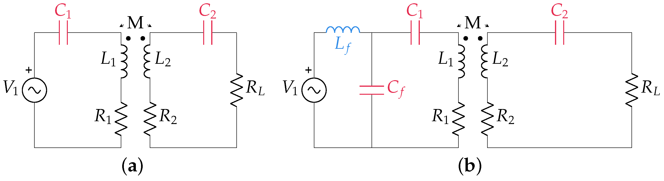
The compensation system is an essential part of inductive wireless charging, since it allows the system to work in resonance at a given frequency (in this case, 85 kHz). There are many types of compensation topologies, starting from the basic topologies—Series–Series (SS), Series–Parallel (SP), Parallel–Series (PS), and Parallel–Parallel (PP)—or more advanced systems, such as LCC-LCC or LCL-LCL.
In this proposal, a comparison between SS and LCC–S will be developed. The reason for this selection is that both systems have good performance in terms of efficiency, as well as good behaviour under misalignment situations [
24]. The structure of the mentioned topologies is represented in
Figure 8. As can be observed, the main difference between these topologies is the inclusion of a filter block (
and
) on the primary side.
The calculation of the parasitic capacitance through Ansys Maxwell has been performed.
The equations governing the proposed systems have slight differences in the calculation of the primary side compensation capacitor. In the case of SS, the primary and secondary side compensation networks can be calculated as shown in Equation (
16).
For LCC–S, the calculation of the primary side capacitor must consider the value of the filter inductor. This element is recommended to keep a value higher than the mutual inductance in order to maintain a good efficiency [
25].
In order to select the optimal solution, a comparative analysis considering the system DC efficiency (
12) is carried out.
Figure 9 shows the comparison between the efficiency of the two types of compensation studied, and the difference between the two structures can be clearly seen.
The new compensation structure is more efficient from 20 V input onwards. For this project, this is not a problem since, at that point, the power on the secondary side is 7.6 W, which is a value far from the target (from 100 W to 240 W). To meet this requirement, the input voltage should be just over 90 V, where the efficiency is close to 80% in the simulation.
Once it can be verified that the efficiency achieved is suitable for this application, it can also be analysed if the current values are appropriate. Higher values of current lead to higher heat losses, which should be avoided in this kind of system, where the final charging power is low. In addition, higher currents require a more precise dimensioning of the system elements, taking into account larger cable diameters and tracks in the power converters, thus increasing the system costs. As can be seen from
Table 5, current values are acceptable for all cases, so this solution can be accepted for this application.
From
Table 5, it can be deduced that efficiency reaches 80% with a power near 300 W, while for the other cases, efficiency keeps under this value. The initial proposed gap between coils (
d) is 5 cm, which is the maximum distance set by the initial requirements of this project. However, this distance value is adjustable, since there is design freedom to choose this variable. For this reason, the proposed modification is to reduce the separation distance from 5 cm to 3 cm in order to increase the system efficiency. When the gap between coils is reduced, the mutual inductance is affected, increasing its value. In this case, the value of
M changes from
H (for d = 5 cm) to
H (for d = 3 cm). The simulation results for these new separation distances are shown in
Table 6.
As can be observed from the previous results, the efficiency values in d = 3 cm are higher than in the case of d = 5 cm. In
Figure 10, a comparison between both cases is represented. Since the efficiencies are higher for all the input voltage values, the selected configuration is d = 3 cm.
Once the design process has been completed, the final parameters of the system are shown in
Table 7. It should be noted that the values of
and
are slightly different from those presented in
Table 3 due to the intrinsic tolerance of the components themselves during the assembly process.
6. Experimental Validation
In order to validate the theoretical analysis, a final prototype is implemented in the laboratory. The structure of the coupled coils has been designed in Solidworks [
26], respecting the geometry and dimensions analysed in Ansys Maxwell for the N = 20 case. Then, the encapsulation has been built with a 3D printer to finally achieve a base structure on which to insert the coil. The material used to build the coil is Litz wire, due to its good behaviour in inductive systems at frequencies of the order of kHz [
27]. In this case, the Litz wire used is the model 600 × 0.05 SE F155 G1 2 Polyester Yarn.
The compensation system capacitors (
,
, and
) have been constructed with polyester models through series-parallel combinations to finally achieve the final values calculated with Equations (
17)–(
19). The compensation inductor (
) has been constructed by using Litz wire, following a toroidal structure.
For the voltage sources, a DC power source model, ITECH-BSS2000, has been used as an input for the power converter. The power converter models used in this project are two CREE evaluation boards KIT8020-CRD-8FF1217P-J, with Silicon Carbide (SiC) MOSFETs model C2M0080120D that offer high-efficiency conversion. These boards include activation and protection circuitry, such as snubber circuits, and low drain-source resistance (
), which leads to lower switching losses (
m
). With regard to the switching control, a PICKIT4 device, together with a dsPIC30f4011 digital signal processor (DSP), is used. The elements mentioned are shown in
Figure 11.
To replicate the effects of seawater, the system has been placed in a water tank, in which salt has been dissolved at a concentration of 3% of the total volume of water [
28], as can be seen in
Figure 12. This is the average percentage of salinity found in seawater.
The experimental validation of this system consists of testing the prototype with a set of input voltage values (from 10 V to 100 V) to achieve 10 different output powers. For all the cases, the experimental waveforms or current and voltage have been measured on the primary and secondary sides, as shown in
Figure 13.
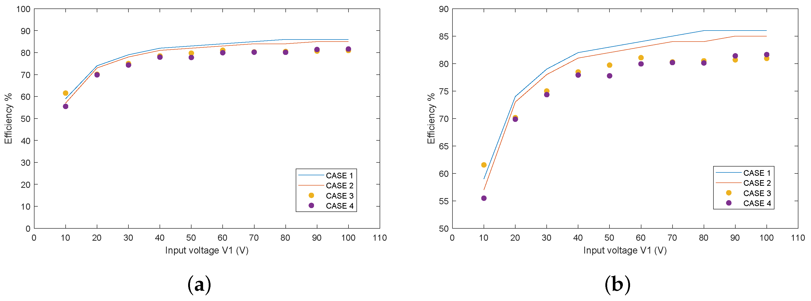
The results achieved are summarised in
Table 8. In this table, four different cases are presented by using different colours to ease the interpretation of the information:
Case 1 (without parasitic capacitance, simulation). This case is related to the simulation of the inductive system in air, without the appearance of parasitic capacitance.
Case 2 (with parasitic capacitance, simulation). In Case 2, the simulations are carried out in seawater, thus considering the appearance of a parasitic capacitance due to seawater conductivity.
Case 3 (without parasitic capacitance, experimental). The third case is related to the experimental validation of the inductive charger in air, where there is no parasitic capacitance.
Case 4 (with parasitic capacitance, experimental). Finally, case 4 contains the experimental validation of the inductive charger in seawater, with 3% salinity.
As can be seen, the efficiency values are near 80% from V to V, so this solution is suitable for the operation power of this project (240 W). As can be observed from this table, the comparative analysis shows that, during the design of the power coils, the consideration of the parasitic capacitance can be avoided under the conditions identified in this paper. In simulation results, considering the parasitic capacitance, the system efficiency decreases in approximately 1% of Case 1 without the parasitic capacitance. This means that the parasitic capacitance effect can be neglected. As can be deduced, the results of the real system validation, considering 3% salinity, follow a similar relation with respect to the simulation results. That is, the effect of the parasitic capacitance is present, but it can be omitted due to the low variations of the system’s overall efficiency.
The comparative analysis of the efficiencies related to each case is represented in
Figure 14. From this figure, it can be deduced that the variations between Case 2 with respect to Case 1 are similar to those between Case 4 with respect to Case 3. In this way, it can be found that the consideration of the parasitic capacitance leads to a weak reduction in the efficiency, both in simulation and experimental results. However, this reduction can be neglected since the efficiency values are reduced, in most cases, to less than 1%.
7. Conclusions
This paper proposes, in contrast to existing literature, the optimisation of the coupled coils of an inductive charger for underwater vehicles with the main objective of minimising the effects of parasitic capacitance.
To find the optimal solution, a set of coils of different areas has been proposed to perform a comparative analysis. The results reveal that the parasitic capacitance value is related to the coil area, so that, in order to minimise its effects, the inductor size should be reduced as much as possible. From this first analysis, together with an efficiency comparative study, it can also be concluded that the optimal value of the selected coil is N = 20, with a circular geometry.
If the compensation system is analysed, it can be determined that the LCC–S offers a good performance in efficiency terms, and it reduces the current values found on the primary circuit, thus reducing the power losses, so that this is the selected topology for the final prototype.
Experimental validations have been performed by using a pair of coupled coils with the same dimensions and geometry that the model previously designed in Ansys Maxwell. Throughout these validations, it has been verified that the system efficiency for all the proposed cases fits with the simulation results.
As future lines, it is intended to test the system considering different salt concentrations, thus verifying the performance of the system in different environments. Furthermore, an analysis about the components tolerance in relation to the system’s efficiency will be considered. In the same way, the analysis related to the eddy currents will be performed in our following works, considering the obtained results to optimise the characteristics of the coupled coils. With regard to the communication, the integration of Simultaneous Wireless Power and Data Transfer (SWPDT) technology will be studied. Finally, in our following works, the tank dimensions will be increased to check the effect it has on the system, since it is intended to use this design in other devices dedicated to underwater exploration or vehicles designed for maintenance tasks in underwater infrastructures.


