Abstract
Grid-forming converters (GFMCs) have emerged as enablers in modern power systems. However, they face the transient stability problem, which hinders them from successful fault ride-through (FRT) and potentially results in the system’s collapse. These problems have drawn increasing attention, leading to a rise in related research. To capture the advancements in the field, this paper reviews studies on the transient stability analysis and enhancement of GFMCs. In particular, the transient stabilities of GFMCs with first- and second-order power control modes are reviewed, and a comprehensive comparison of the two modes is provided. Additionally, this paper classifies the transient stability enhancement methods of GFMCs into six types: active power, reactive power, voltage amplitude, virtual impedance, inertia and damping regulations. Moreover, this paper summarizes the effects and limitations of each method from the perspective of practical application. Based on the analysis, this paper further discusses future research directions for the transient stability of GFMCs.
1. Introduction
To achieve clean energy targets and meet growing energy demands, renewable energy sources are gradually replacing traditional energy sources, leading to innovations in modern power systems [1]. Notably, renewable energy sources primarily connect to the grid through power converters. Therefore, as this energy transition continues, modern power grids are gradually evolving into more-electronic power systems. Presently, the mainstream grid-tied converters are grid-following converters (GFLCs), which operate as current sources. These converters make it difficult to provide critical services such as the inertia, damping and frequency/voltage regulation that are traditionally offered by synchronous generators (SGs) [2]. Therefore, this high proportion of GFLCs has severely challenged the safe and stable operation of power systems [3,4].
The concept of GFMCs was originally proposed to address stability challenges in microgrids and islanded power systems [2]. Unlike GFLCs, which act as controlled current sources, GFMCs emulate SGs and function as controlled voltage sources [5,6]; thus, they can support both the voltage and frequency. Through power control, GFMCs achieve synchronization with the grid without a phase-locked loop (PLL) [7]. Compared to GFLCs, GFMCs offer numerous advantages including independent operation, flexible provision of inertia, fast frequency/voltage regulation and great stability in weak grids [3].
However, GFMCs suffer from stability problems. Based on the size of the disturbance signal, the stability problems of GFMCs can be categorized into small-signal and large-signal stability problems. The small-signal stability of grid-forming converters has been extensively studied. For example, References [1,8,9]. However, the large-signal stability, which involves nonlinear analysis, requires further investigation. Specifically, transient stability, a type of large-signal stability related to active power transfer and its limitations, remains a hot topic. The analysis and enhancement of the transient stability of GFMCs are mentioned in References [1,7,8]. However, there is no review that deals specifically with the transient stability of GFMCs. Different transient stability enhancement methods have not been systematically summarized. This paper is dedicated to filling this gap.
The transient stability of GFMCs refers to the ability to maintain synchronization with other power sources under large-signal disturbance, such as grid voltage sags [10], transmission line faults [11] and load swings. The effects of different disturbances are discussed in Reference [12], where many of them share the similarity that they cause a lower power angle curve due to changes in line impedance or grid voltage, which leads to transient instability.
The transient behavior of GFMCs varies with different power control schemes. There are many emerging control methods of GFMCs including droop control, virtual synchronous machine control (VSM) and virtual oscillator control (VOC). Based on the order of the control (i.e., the order of the differential terms in the control equations), the active power control strategies of GFMCs are generally classified into first-order (e.g., droop control) and second-order controls (e.g., VSM). For droop-controlled GFMCs, an overshoot in power angle does not occur [13,14]. The stable or unstable operation of droop-controlled GFMCs during transients is directly related to the existence or absence of equilibrium points (EPs). The second-order characteristics of VSMs make their transient stability behavior similar to that of SGs, allowing the application of the equal-area criterion that is widely used in VSM stability analysis [13,15]. The analysis of the transient stability of VOC is discussed in References [16,17]. VOC is based on non-linear control, which shares few similarities with the two methods mentioned above and cannot work together with these methods. Therefore, we do not discuss VOC in this paper. To calculate the boundary of the stability area and guide the design of the control system, several methods are used to analyze transient stability. The most widely used are time-domain simulations such as phase portraits, and energy-based methods such as equal-area criteria and Lyapunov’s direct method. There are also some emerging methods that could be able to calculate the basin of attraction more precisely [18].
We searched the keywords “grid-forming”, “transient stability”, “synchronization stability”, “transient stability enhancement”, “droop control”, “Virtual synchronization Machine (VSM)” and so forth on IEEE Xplore and Elsevier ScienceDirect. Moreover, the enhancement method related to current limitation is not included, due to its PLL-based synchronization scheme being similar to grid-following control. Finally, we identified more than 50 papers from 2015 to 2025. After summarizing the enhancement methods for the transient stability of GFMCs, as shown in Table 1, we found that several parameters related to active power transmission could affect transient stability, i.e., the active power, reactive power, voltage amplitude, transmission line impedance, inertia and damping. In order to increase the stability margin and enhance the transient stability, a variety of methods have been proposed. References [19,20,21,22,23,24,25] designed various controllers to add a negative compensation for active power references or to modify the active power control loop, but these might deteriorate the frequency stability. References [10,26,27,28,29,30] changed the voltage amplitude or reactive power, References [11,31,32,33,34,35,36,37] proposed different virtual impedances, with which the line loss could increase. In VSMs, the transient stability is further affected by virtual inertia and virtual damping, as these parameters modify the power angle response rather than the active power transmission limit. Therefore, References [38,39,40,41,42,43,44,45,46] changed the inertia or damping when faults occurred, or used the transient damping method (TDM); however, modifying the inertia could affect the frequency stability, and adjusting the damping could change the power distribution results. The effectiveness of the methods mentioned above has been verified by time-domain simulations and experimental tests according to the reference values. At present, transient stability analysis and enhancement methods have found some applications in transmission systems [47], wind power generation [48] and islanded grids [49,50]. Moreover, we also noticed some other emerging methods, which will be introduced later in this paper.

Table 1.
Comparison of Transient Stability Enhancement Methods.
This paper provides a systematic overview of the transient stability analysis and enhancement methods for GFMCs. Section 2 introduces a general model for GFMCs and two types of control methods. Section 3 explores the transient stability mechanisms of different control methods. In Section 4, the existing methods for enhancing transient stability are categorized into six types: active power regulation, reactive power or voltage regulation, virtual impedance regulation and inertia or damping regulation. Finally, Section 5 discusses the challenges faced in this area and outlines prospects for future research.
2. System Configuration and Control Structure of GFMCs
2.1. Schematics and Control Structure of GFMCs
Figure 1 presents the schematic diagram of a GFMC. In this diagram, the converter is connected to the grid through an LCL filter, which includes the converter-side inductance Lgi, the filtering capacitor Cgf and the grid-side inductance Lgg. The grid is modelled as a series connection of the grid inductance Ls, grid resistance Rs and voltage source vsabc. The converter regulates the voltages across Cgf (i.e., vgfabc) and operates as a controllable voltage source. Additionally, vgabc represents the voltage at the PCC.
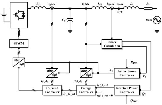
Figure 1.
System configuration and control structure of the GFMC.
Figure 1 also illustrates the control block diagram of the grid-forming converter. The subscripts d and q represent variables in the Park-transformed synchronous reference frames, where “ref” indicates the reference value. The active power Pg and reactive power Qg are calculated from vgfabc and igiabc. Additionally, θg refers to the phase angle of the grid-forming converter.
Neglecting the dynamics caused by voltage and current inner loops, and assuming that the three-phase symmetrical and current-limiting protections are not triggered, the grid-forming converter can be simplified as a controlled voltage source, as shown in Figure 2. Rgs and Xgs are the resistance and reactance between the converter and the grid, respectively. Vgf and Vs denote the voltage of the converter and the grid, respectively. δg signifies the phase angle difference between Vgf and Vs, conventionally defined as the virtual power angle. Based on this simplified model, the active power Pg and reactive power Qg transmitted by the line can be derived as follows:
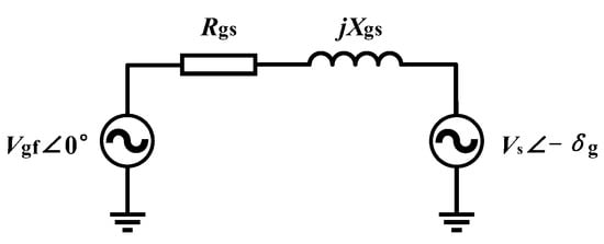
Figure 2.
Simplified model of the GFMC and grid.
When the default grid inductance is much larger than the resistance, i.e., considering Rgs = 0, more concise expressions can be obtained as follows:
2.2. First-Order Control Scheme: Droop Control
Figure 3 shows the block diagram of droop control. The symbol Δ denotes the parameter change. S0, V0 and ω0 are the nominal power, voltage frequency and angular frequency, respectively. ω is the angular frequency. s represents the Laplacian complex frequency variable. Kpf and Kqv represent the droop gains of the active power control and reactive power control. Droop control emulates the droop characteristics in SGs. The control equation of droop control is as follows:
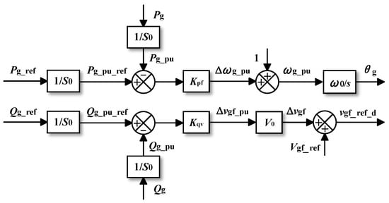
Figure 3.
Block diagram of droop control.
Moreover, the power-synchronization control (PSC) mentioned in some references shares the same control laws as droop control. The structural diagrams of the two can be transformed into each other [13]. When analyzing transient stability, both are considered as first-order systems and there is no difference.
2.3. Second-Order Control Scheme: VSM Control
Figure 4 presents a block diagram depicting the structure of VSMs. VSM control, which is a second-order control method, emulates the rotational dynamics of a synchronous generator rotor described by the swing equation. The control equation of VSM control is as follows:
where H and τ denote the inertia constant of active and reactive power control, respectively. Dp and Dq are the damping coefficients of active power control and reactive power control, respectively. Ignoring the low-pass filtering of constant terms ω0 and Vg_ref, we obtain Equations (9) and (10) [13].
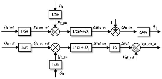
Figure 4.
Block diagram of VSM control.
It is worth mentioning that some GFMCs with drop control incorporate a first-order low-pass filter in the forward channel, at which point, the system becomes second-order, and its control equation shares the same formation as Equations (9) and (10), which is equivalent to VSM control [51].
3. Transient Instability Mechanism of GFMC
3.1. Transient Instability Mechanism of Droop Control
By replacing the angular frequency in Equation (5) with the differential of the phase angle, substituting the left-hand side with dδg/dt according to the definition of the power angle mentioned in Section 2, and finally substituting Equation (3), the first-order nonlinear differential equation of the power angle for grid-connected converters under droop control can be derived, as shown in Equation (9):
Solving the nonlinear equation is challenging and is often analyzed using the phase portrait. The dδg-δg curve of droop control forms a curve resembling y = Asinx + C (where A and C are constants). There exists a moment when dδg/dt = 0, i.e., the input mechanical power equals the output electrical power, or Pg = Pg_ref, which serves as a criterion for assessing the transient stability of SGs or GFMCs [12]. Due to differing parameter values, the dδg-δg curve of droop control may or may not intersect the dδg/dt = 0 axis, indicating the presence or absence of EPs (equilibrium points).
As shown in Figure 5, for such first-order nonlinear systems, if EPs exist, δg monotonically approaches the stable equilibrium point (SEP) without overshooting or transient instability issues. If EPs do not exist, δg will monotonically approach infinity, and dδg/dt will oscillate sinusoidally. It is noteworthy that even if δg exceeds the critical clearing angle (CCA) during fault clearance, i.e., δu, as long as the EPs exist after clearing, the system can recover stability after oscillating for one cycle [14].
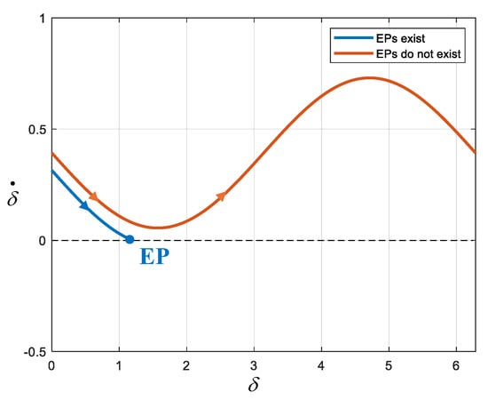
Figure 5.
Phase portrait of droop control.
In summary, for GFMCs with droop control, transient instability does not occur when an SEP exists after a disturbance. When no EP is initially present, as long as the EPs are restored after fault clearance, neither the clearing time nor the clearing angle affects stability. This advantage is not available in VSMs.
3.2. Transient Instability Mechanism of VSM Control
Applying certain transformations to Equation (7) yields the power angle differential equation for VSMs, as shown in Equation (10). This represents the swing equation for VSMs.
The phase portrait of VSM is shown in Figure 6. It is evident that the VSM’s power angle response exhibits overshoot, unlike droop control, and oscillates multiple times before converging to an SEP if the system is stable. When transient instability occurs, δg continuously increases, and the phase portrait shows a diverging pattern.
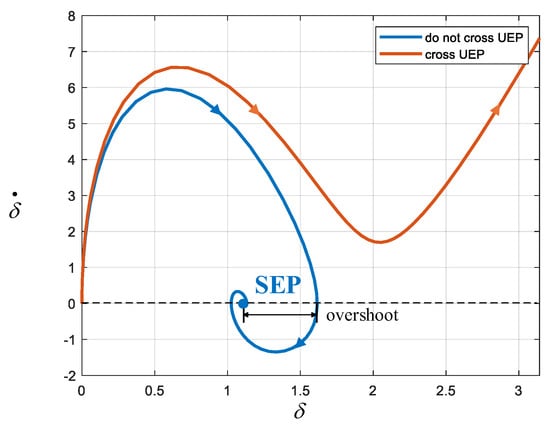
Figure 6.
Phase Portrait of VSM control.
The equal-area criterion provides an intuitive assessment of the transient stability of SGs or VSMs in an infinite-bus system without directly solving differential equations. This criterion aids in understanding the transient instability mechanisms of SGs and GFMCs with VSM control. The criterion is expressed by Equations (11) to (13), where δ0 denotes the initial power angle, δm is the maximum power angle reached during oscillations and δ1 is the power angle after stability is restored.
As shown in the differential equation given by Equation (10), the rotor accelerates when the input mechanical power is greater than the output electrical power, and decelerates otherwise. The essence of the equal-area criterion is that if an SG can return to a stable state after a disturbance, the kinetic energy of the rotor or virtual rotor E1 gained during acceleration must equal the kinetic energy E2 lost during deceleration. In other words, the area under the power angle curve during acceleration (A1) must equal the area during deceleration (A2), as illustrated in Figure 7 [52]. When δm reaches the unstable equilibrium point (UEP), the deceleration area reaches its maximum, placing the system in a critical state. From this, the CCA can be calculated. If the acceleration area is too large and the deceleration area is too small to offset it, the power angle will surpass the UEP, leading to transient instability, as shown in Reference [15].
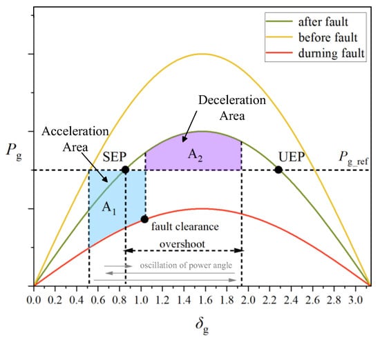
Figure 7.
Equal-area criterion.
The classical equal-area criterion for analyzing SGs ignores damping, assuming Dp = 0. However, for VSMs, the damping value can be arbitrarily set and sometimes cannot be ignored. To address this issue, Reference [21] developed a Lyapunov energy function that incorporates damping to analyze the transient stability of VSMs. In practice, damping aids system stability [52], and ignoring damping can lead to a more conservative assessment of system stability. Therefore, the area criterion remains valuable in engineering applications of GFMCs.
In summary, even if EPs exist after a disturbance or fault isolation, VSMs might still experience transient instability. This instability occurs when the power angle crosses the UEP during its motion.
4. Transient Stability Enhancement Methods of GFMCs
4.1. Active Power Regulation
As previously mentioned, for VSMs, if the post-fault Pg-δg curve cannot provide a deceleration area equal to the acceleration area, instability will result. A straightforward method to improve transient stability, therefore, is to modify Pg_ref to reduce the acceleration area and increase its deceleration area after a fault occurs. In fact, many enhancement methods do not change Pg_ref directly, but design additional active power controllers (AAPCs), which add a compensation value ΔP to the input of the active power control, and detect physical quantities such as the voltage, reactive power, etc., to determine the magnitude of ΔP.
As shown in Figure 8, the method proposed in Reference [21] achieves this by detecting voltage sags to determine whether to add additional torque to reduce Pg_ref. ΔP is applied through an additional torque, ΔT, which changes the actual input active power reference. Similarly, Reference [19] detects the depth of the voltage sag, which in turn calculates the extent to which the Pg-δg curve has dropped, and adaptively adjusts ΔP such that EP exists. The ΔP is expressed by Equation (14), where Pg|t=0+ and Pg|t=0− represent the transmission power of the power grid system after and before the fault occurs, and Vgf′ and Vs′ represent the voltage after the voltage sag [19]:
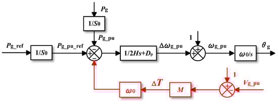
Figure 8.
Proposed method in [21].
In addition to detecting voltage, Reference [22] proposes a method for detecting the reactive power to determine whether a fault has occurred based on the coupling of reactive power and voltage, i.e., if converters output more reactive power to provide voltage support after voltage sags [22], as shown in Figure 9. In order to enhance the stability, a first-order inertial link is added to the AAPC to act as a time lag. Reference [22] also experimentally verified that the larger the Kq is, the better the enhancement effect of transient stability is.
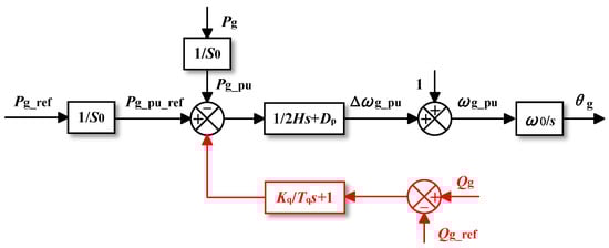
Figure 9.
Proposed method in [22].
Reference [20] enhances transient stability by installing a resistive superconducting fault current limiter (R-SFCL) on the transmission line. SFCL is a current-limiting protection device that operates in a superconducting state under normal conditions. During a fault, it heats up beyond its critical temperature, causing its resistance to increase sharply. Once the SFCL is activated, the grid resistance increases, raising the Pg-δg curve and reducing the acceleration area. The power dissipated by the SFCL PSFCL can be accurately calculated based on its resistance characteristics. During a fault, it can be assumed that the SFCL consumes much more power than other parts and becomes the main component of the output power of the converter. Therefore, the acceleration area can be greatly reduced by simply setting Pg_ref to PSFCL [20].
In addition to designing AAPC, Reference [23] proposes a mode-adaptive method that alters the feedback mode of the active power control loop of VSMs, as depicted in Figure 10. By analyzing the transient instability process of the VSM from the perspective of feedback modes, it becomes apparent that if, after a fault, the power angle exceeds a UEP (or δg surpasses π/2 when no EP exists), the active power control loop shifts from negative feedback to positive feedback, causing δg to continue increasing. To address this, the proposed method detects ΔPg, d(ΔPg)/dt and Δω to determine the feedback mode. A coefficient k is added to the forward channel, and if the system enters positive feedback, the sign of k is reversed, converting the system back to negative feedback. This ensures that the power angle decelerates, avoiding instability. Consequently, if EPs exist, δg will gradually converge to the new SEP; if not, the power angle will oscillate around π/2 until the EPs are restored. For droop control, as long as the EPs exist, transient stability issues do not arise, and no adjustments to the active power control loop are necessary.
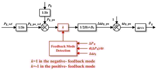
Figure 10.
Proposed method in [23].
In droop control, transient stability issues arise only when EPs do not exist. Therefore, methods for improving transient stability in droop-controlled systems need to focus specifically on scenarios where EPs are absent. References [24,25] introduced a method based on power angle estimation, which ensures that, in the absence of EPs, the power angle oscillates within a small range around π/2. As an accurate calculation method for the power angle does not exist, they introduce the concept of virtual orthogonal power Pv in the αβ-frame, as shown in Equation (15), where igvα and igvβ are virtual grid currents. The power angle can then be predicted using Pv and the converter’s actual output power Pg, as indicated in Equation (16).
The block diagram of this method is illustrated in Figure 11, where the hysteresis comparator is primarily used to trigger the transient stability enhancement method when the power angle approaches π/2, while remaining inactive when it is farther from π/2. As seen in Equation (15), near π/2, the ratio Pg/Pv oscillates between positive and negative values, allowing the system to switch between two modes and causing the power angle to fluctuate around π/2.
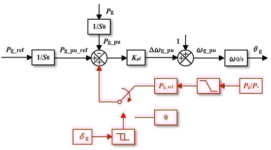
Figure 11.
Proposed method in [24,25].
4.2. Voltage Regulation
As seen from Equation (3), the active power transmission limit, Pg_max, is related to Vgf. Many references have derived the relationship between Vgf and δg for GFMCs using reactive drop control. The general shape of the Vgf-δg curve and phase portraits with reactive power droop control are shown in Reference [13].
Reference [30] provides a detailed analysis of the dynamic process within the reactive control loop post-fault, highlighting that the introduction of positive feedback in the reactive control loop leads to further voltage sags. After a fault occurs, Vgf decreases monotonically with increases in δg, worsening the transient stability. Consequently, without triggering the current-limiting algorithm, transient stability margins can be improved by appropriately increasing Vgf after a fault.
Reference [10] introduces methods for voltage magnitude management, quantitatively establishing the relationships between Pg_max and Vgf_ref. The Pg_max-Vgf_ref curve is depicted in Figure 12. This allows for the calculation of the critical voltage magnitudes required to prevent system instability, guiding the design of control parameters.
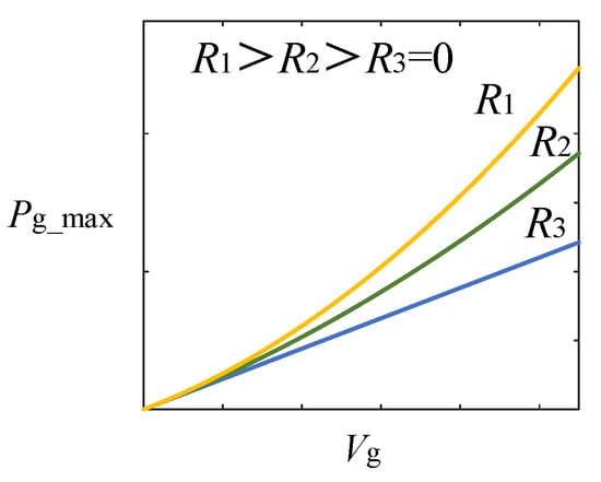
Figure 12.
Pg_max-Vg_ref curve [10].
References [28,29] proposed a fast voltage booster (FVB) for power systems composed entirely of GFMCs. FVBs are inspired by the excitation boosters (EBs) used in SGs to improve transient stability in multi-machine systems [28]. Two types of FVB have been proposed, one based on local measurements, i.e., a local fast voltage booster (FVB-L), and another designed for multi-machine systems, i.e., a fast voltage booster using a wide-area control system (FVB-WACS). Once the FVB is activated, the supplementary voltage set point Δvgf_ref + vgf_ref is maintained if at least one of the two following conditions are satisfied: an undervoltage or frequency greater than or equal to the threshold [28,29].
4.3. Reactive Power Regulation
Given the strong coupling between voltage and reactive power, as shown in Equation (6), increasing Qg_ref can indirectly raise Vgf, thus enhancing the transient stability. Reference [30] also shows the effect of increasing reactive power, showing that it can restore EPs. Many references have designed novel controllers that modify the reactive power when faults occur.
Except for voltage amplitude management, Reference [10] also proposes the method of reactive power injection; the Pg_max-Qg_ref curve for this is shown in Figure 13.
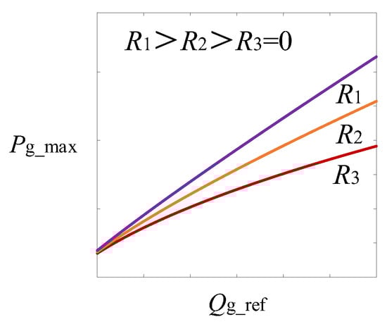
Figure 13.
Pg_max-Qg_ref curve [10].
In Figure 14, where ωs denotes the angular frequency of the grid, the improved method proposed in Reference [26] adds an additional path to feedforward the frequency difference between the VSM and grid and introduce it into the reactive power control loop. After a fault occurs, the GFMC is temporarily out of synchronization with the grid and the frequency of the GFMC is deviated. Therefore, the magnitude of the frequency deviation can be used to adaptively regulate the reactive power. Reference [26] also verified that the larger the coefficient K, the faster the system converges and the better the transient stability enhancement. Moreover, this method could improve the frequency stability.
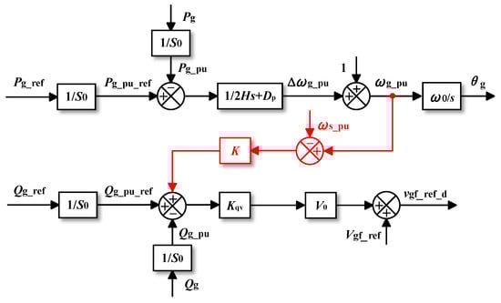
Figure 14.
Proposed method in [26].
Reference [27] modifies the control structure and proposes an enhanced transient stability control based on VSM, in which ΔP is introduced into the reactive power control loop, as shown in Figure 15. An iterative algorithm is also proposed to calculate the control gain K. Reference [27] proves that the proposed method does not change EPs, but makes Pg (K > 0) larger than Pg (K = 0) as dPg/dK > 0; as such, the proposed method alters the Pg-δg curve during a fault, reducing the acceleration area and increasing the deceleration area.
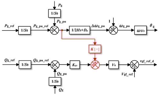
Figure 15.
Proposed method in [27].
4.4. Virtual Impedance Regulation
A GFMC with virtual impedance (VI) is illustrated in Figure 16. As shown in Figure 17, after the system collects the current, it multiplies it by the virtual impedance to obtain the voltage attributed to the virtual impedance. This voltage offset of the d-axis and q-axis, i.e., Δvgf_d and Δvgf_q, is then added to the original reference voltage of the voltage control loop.
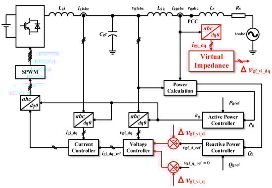
Figure 16.
GFMCs with VI.
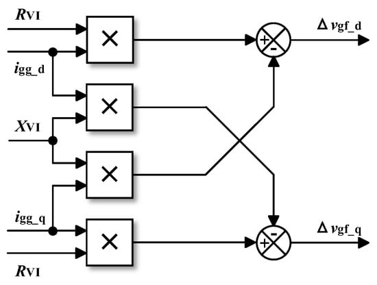
Figure 17.
Block diagram of VI.
The current research on VI has devoted substantial efforts to its application for improving small-signal stability and limiting the current during short-circuit faults [32]. Regarding transient stability, Reference [34] reveals that the integration of VI reduces Pmax, decreases the stability margin, and thereby worsens transient stability. Consequently, there exists a conflicting relationship between the enhancement of small-signal and large-signal stability using virtual impedance [34], as there does between current limitation and large-signal stability [33]. In practice, these studies primarily consider cases of increasing the converter’s output resistance. Some new studies have proposed other forms of virtual impedance to improve transient stability.
References [11,37] propose a method for adjusting the impedance ratio σ of the converter’s output impedance. i.e., X/R. As illustrated in Figure 18, increasing σ from 0.1 to 10 significantly enhances the transient stability margin of the converter. Moreover, Reference [33] proposes an adaptive control method; it alters σ to keep dPg/dt = 0 constantly. Additionally, Reference [11] derives the stability boundaries for the impedance magnitude and phase angle, providing valuable guidance for parameter design.
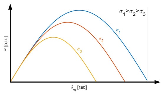
Figure 18.
Pg-δg curve, including VI for various σ [37].
Reference [32] concludes that increasing the grid resistance can enhance transient stability, which differs from the effects of increasing the converter’s output resistance. As shown in Figure 19, Reference [32] suggests a method that increases grid resistance using VI. In this method, the VI component no longer modifies the reference value of the voltage loop, but instead influences the active power control loop. The PI controller is designed to make Pg track the Pg_ref in normal conditions (k = 1). The VI component is used to calculate the virtual power at the virtual PCC with the added virtual grid resistance, i.e., Pvir, as depicted in Figure 20. Pvir is expressed as [32]:
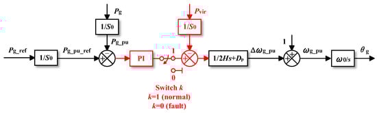
Figure 19.
Proposed method in [32].
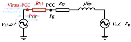
Figure 20.
Simplified model of VSM using the proposed method in [32].
Moreover, grid inductance could also improve transient stability. Reference [35] reveals that not only physical inductance, but also virtual inductance, has the effect of suppressing the overshoot of Pg, Qg, ωg and Vgf.
Beyond increasing grid impedance, Reference [31] demonstrates the effect of varying the virtual synchronous reactance, virtual asynchronous reactance and virtual resistance of the VSM on a number of parameters including the transmission margin. Simulation and experimental results indicate that the most effective method for improving transient stability is to increase d-axis negative reactance while simultaneously increasing q-axis positive reactance. In contrast, the least effective method is increasing only the positive reactance along the q-axis.
4.5. Inertia Regulation
The virtual inertia and damping of a VSM have distinct effects on transient stability. As the virtual inertia increases, the impact of damping is reduced because Dp × dδ/dt + J × d2δ/dt2 = Pg_ref − Pg remains constant, leading to a decrease in the CCA. However, the rate at which the power angle increases also slows down, resulting in a longer critical cutting time (CCT).
Based on this principle, the approach to adjusting inertia remains consistent across different methods. Specifically, during faults or when the VSM is accelerating, greater inertia is required to counteract frequency deviations and reduce the acceleration area. Conversely, after a fault is cleared or when the VSM is decelerating, reduced inertia is necessary to enable the system to quickly converge to a new EP and increase the deceleration area.
References [40,44] both describe methods that adjust inertia after a fault is detected. During transient processes, both studies generally follow the same principle in adjusting inertia. The key difference lies in the detection mechanism: Reference [40] monitors the voltage sag to determine whether a fault has been cleared, while Reference [44] detects the frequency deviation Δω between the converter and the grid, as well as the angular acceleration dω/dt of the converter’s phase angle, to assess the VSM’s acceleration and deceleration states.
Moreover, Reference [42] introduces an adaptive inertia adjustment based on the previously discussed principles. The expression for adaptive virtual inertia is provided as follows [42]:
4.6. Damping Regulation
Damping generally contributes positively to transient stability [40]. As shown in Figure 21, when damping is considered in the equal-area criterion, the accelerating area (A1) decreases, while the decelerating area (A2) increases. Reference [53] proposes a damping energy approximation method to depict the transient stability boundary more accurately; thus, the effect of damping is visualized and quantitative. Therefore, as revealed in Reference [40], increasing the damping term could improve transient stability.
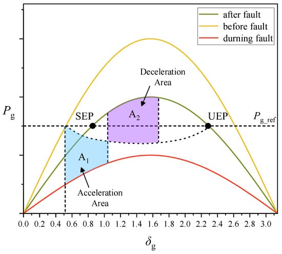
Figure 21.
Effect of damping on the Pg-δg curve [40].
References [38,45] employ TDM, which represents the mainstream approach for achieving adaptive damping adjustment. This method feeds Δω back into the active power control loop, and the block diagrams of the two transient damping structures are shown in Figure 22 and Figure 23. After introducing transient damping, the VSM’s control equation is given as follows [38]:
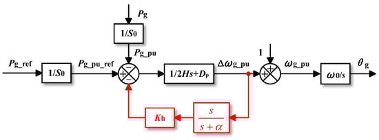
Figure 22.
Proposed method in [45].
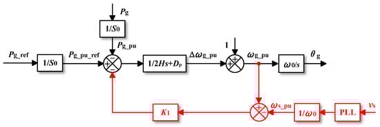
Figure 23.
Proposed method in [38].
In this context, K represents the transient damping gain, where the term KΔω functions similarly to damping. Since the VSM frequency matches the grid frequency in a steady state, resulting in Δω = 0, transient damping can enhance the transient response without altering steady-state performance or affecting the frequency stability [45].
The distinction between References [38,45] lies in their approach: Reference [45] calculates the frequency deviation Δω by measuring the grid frequency via a phase-locked loop and then comparing it with the VSM frequency, while Reference [38] naturally derives Δω from the active power control loop. Additionally, in Reference [38], a high-pass filter is employed to eliminate the Δω offset caused by minor power angle oscillations in a steady state, ensuring that the P–f droop characteristic remains unaffected. Although there are other methods for implementing transient damping, they often involve complex dynamic responses and high-order filters, and they lack the analysis of large-signal stability [38].
Reference [46] integrates both the adaptive adjustment methods discussed above and introduces an additional frequency control mechanism. The structure of the modified control system is illustrated in Figure 24. The revised control equation is presented as follows [46]:
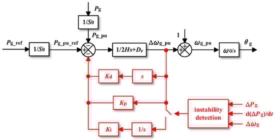
Figure 24.
Proposed method in [46].
This method places a PID controller in the frequency deviation feedback loop, where the derivative term adjusts the equivalent virtual inertia, and the proportional term provides transient damping. Upon detecting a fault, this method not only allows the simultaneous adjustment of inertia and damping, but also utilizes the integral term to reduce the active power reference Pg_ref, thereby further enhancing the transient stability.
Reference [39] introduced differential compensation links to improve damping, as depicted in Figure 25. The differential compensation link and the original inertial link form a led/lag compensator [39]. The experimental results demonstrate that the method has the effect of suppressing the power angle overshoot, and the larger the mp, the better the transient stability enhancement.
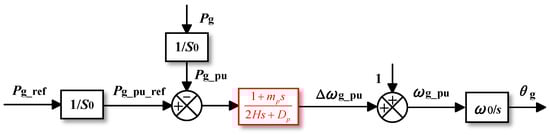
Figure 25.
Proposed method in [39].
Many of the above methods elicit angular frequency-dependent quantities as feedback quantities. However, Reference [41] proposes a dynamic damping control (DDC) method for detecting the voltage, which works during voltage sags, as shown in Figure 26.
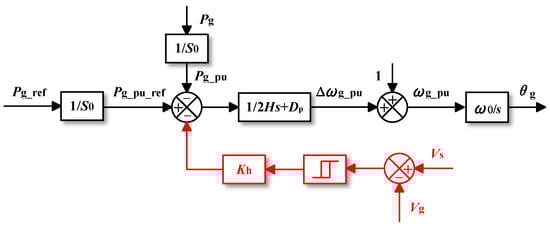
Figure 26.
Proposed method in [41].
4.7. Comparison of Transient Stability Enhancement Methods
Different transient stability enhancement methods have different characteristics, as shown in Table 2.
Table 2.
Comparison of Transient Stability Enhancement Methods.
Active power regulation, reactive power regulation and virtual impedance regulation can change the active power transfer limits and have the ability to restore EPs after a fault occurs. The difference is that active power regulation lowers the active power reference, while the other three methods lift the Pg-δg curve.
However, inertia regulation and damping regulation cannot restore EPs. Both methods slow down the dynamic process; the inertia regulation increases the CCA while the damping regulation increases the CCT [40]. The increase in damping reduces the amount of overshooting and prevents the power angle from crossing the UEP, while the increase in inertia diminishes the effects of damping; both help avoid the instability of VSM.
While improving transient stability, these methods might have some impact on other aspects of GFMCs’ performance. Reducing the reference value of the active power affects the frequency stability, and it conflicts with IEEE Standard 1547–2018, which requires that the Pg_ref does not drop excessively during fault ride-through [26]. The increase in reactive power and voltage will increase the line loss, and the current saturation will be triggered when the current is too large, which will greatly reduce the stability margin [54]. Changing the virtual impedance can negatively affect voltage adjustment. In addition to Pg_ref, a reduction in inertia can also worsen the frequency stability. Changing the damping affects the power distribution results, as damping is equivalent to the droop gains.
5. Future Trends
To meet the demands of large-scale engineering applications for GFMCs, further research is needed in the following areas:
5.1. Comprehensive Stability Enhancement
A combination of different stability enhancement approaches may be required to balance various performance aspects including transient stability. Some references have proposed methods to balance transient stability with frequency stability. Reference [19] uses a voltage feed-forward path to guarantee frequency stability while introducing AAPC. To balance small-signal and large-signal stability, the method proposed in [37] reduces σ during transients to suppress the current, while increasing it during quasi-steady and steady states to maintain power angle stability. Reference [39] proposes a parameter design guideline that balances damping and inertia, hence the transient stability and frequency stability. In the future, comprehensive regulation for the parameters of GFMCs might be a promising method for transient stability enhancement, where there are several parameters instead of a single one. For example, Reference [55] proposes active power and voltage cooperative control to improve the fault ride-through capability of GFMCs.
5.2. Transient Stability Enhancement Method for Multi-Machine Systems
The future power system will consist of a large number of GFMCs, in addition to a certain number of GFLCs. There are various interactions between the grid and GFMCs in single-machine systems, and various interactions between GFMCs in multi-machine systems, which may lead to transient instability and the shutdown of multiple converters. For example, Reference [56] discusses the instability mechanism of nonuniform damping in GFMC-penetrated multi-machine systems, and Reference [57] analyzes the transient stability of parallel grid-tied GFMC systems when considering reactive power control. However, transient stability studies of multi-machine systems are still in their infancy and have mainly focused on islanded microgrids [58,59], the traditional application area of GFMCs [60]. There is not much literature on transient stability enhancement methods for multimachine systems, and the main methods currently are FVB-WACS [28,29], power angle freezing [61,62], active power interference [60] and inertial center frequency oscillation control [60]. In addition to the interaction between GFMCs, the interactions between GFMCs and GFLCs also need attention [58,63]. In addition, the effects of various previously proposed transient stability enhancement methods for single-machine systems on multi-machine systems should not be ignored and need to be investigated.
5.3. Utilizing Advanced Control Theory
Currently, the idea of adaptive control is more widely used in the enhancement of the transient stability of GFMCs. In addition, model predictive control is a more promising direction for the future [64]. Moreover, some methods based on machine learning such as deep reinforcement learning [65] and data-driven predictive control [66] could also be introduced to enhance transient stability. There is little research on the implementation of machine learning in the transient stability enhancement of GFMCs, so this might be a brand-new research field.
6. Conclusions
This paper presents a review of methods for analyzing and enhancing the transient stability of GFMCs. Firstly, the general structure of GFMCs was given, and two commonly used control methods—droop control and VSM control—were introduced. The GFMC with droop control is a first-order system, while VSM control is a second-order system. Then, this paper analyzed the instability mechanism of GFMCs using these two types of control methods. Droop control has no stability problems as long as EPs exist, whereas VSM control has overshooting due to the fact that it is a second-order system, and because there is a possibility of instability when EPs exist. Then, this paper listed six transient stability enhancement methods, i.e., active power, reactive power, voltage amplitude, virtual impedance, inertia and damping regulations, and describes their principles, lists some specific implementations and compares their improvement effects and drawbacks. Finally, this paper concludes the future development trend of some transient stability improvement methods.
Author Contributions
Investigation, X.C. and W.S.; writing—original draft preparation, X.C.; writing—review and editing, W.S., Q.Y. and J.F.; visualization, X.C. and Q.Y.; project administration, J.F.; funding acquisition, J.F. All authors have read and agreed to the published version of the manuscript.
Funding
This research was funded by Department of Science and Technology of Shandong Province: ZR202210270088; Jinan Science and Technology Bureau: 202228069; Guangdong Basic and Applied Basic Research Foundation: 2022A1515110422; National Natural Science Foundation of China: 20221017-9, Grant 52377192, and Grant 12411530110.
Data Availability Statement
The original contributions presented in the study are included in the article, further inquiries can be directed to the corresponding author.
Conflicts of Interest
The authors declare no conflicts of interest.
References
- Wang, X.; Taul, M.G.; Wu, H.; Liao, Y.; Blaabjerg, F.; Harnefors, L. Grid-Synchronization Stability of Converter-Based Resources-An Overview. IEEE Open J. Ind. Appl. 2020, 1, 115–134. [Google Scholar] [CrossRef]
- Rocabert, J.; Luna, A.; Blaabjerg, F.; Rodríguez, P. Control of Power Converters in AC Microgrids. IEEE Trans. Power Electron. 2012, 27, 4734–4749. [Google Scholar] [CrossRef]
- Babu, V.V.; Roselyn, J.P.; Nithya, C.; Sundaravadivel, P. Development of Grid-Forming and Grid-Following Inverter Control in Microgrid Network Ensuring Grid Stability and Frequency Response. Electronics 2024, 13, 1958. [Google Scholar] [CrossRef]
- Ndreko, M.; Rüberg, S.; Winter, W. Grid forming control scheme for power systems with up to 100% power electronic interfaced generation: A case study on Great Britain test system. IET Renew. Power Gener. 2020, 14, 1268–1281. [Google Scholar] [CrossRef]
- Yu, C.; Xu, H.; Chen, C.; Sun, M.; Fu, X.; Zhang, X. A unified approach to modeling and stability equivalence analysis for grid-forming and grid-following converters. Electr. Power Syst. Res. 2024, 235, 110861. [Google Scholar] [CrossRef]
- Li, C.; Huang, Y.; Deng, H.; Zhang, X.; Zhao, H. A novel grid-forming technology for transient stability enhancement of power system with high penetration of renewable energy. Int. J. Electr. Power Energy Syst. 2022, 143, 108402. [Google Scholar] [CrossRef]
- Rosso, R.; Wang, X.; Liserre, M.; Lu, X.; Engelken, S. Grid-Forming Converters: Control Approaches, Grid-Synchronization, and Future Trends-A Review. IEEE Open J. Ind. Appl. 2021, 2, 93–109. [Google Scholar] [CrossRef]
- Zhang, H.; Xiang, W.; Lin, W.; Wen, J. Grid Forming Converters in Renewable Energy Sources Dominated Power Grid: Control Strategy, Stability, Application, and Challenges. J. Mod. Power Syst. Clean Energy 2021, 9, 1239–1256. [Google Scholar] [CrossRef]
- Yang, Z.; Zhan, M.; Liu, D.; Ye, C.; Cao, K.; Cheng, S. Small-Signal Synchronous Stability of a New-Generation Power System With 100% Renewable Energy. IEEE Trans. Power Syst. 2023, 38, 4269–4280. [Google Scholar] [CrossRef]
- Si, W.; Fang, J. Transient Stability Improvement of Grid-Forming Converters through Voltage Amplitude Regulation and Reactive Power Injection. IEEE Trans. Power Electron. 2023, 38, 12116–12125. [Google Scholar] [CrossRef]
- Li, M.; Shu, S.; Wang, Y.; Yu, P.; Liu, Y.; Zhang, Z.; Hu, W.; Blaabjerg, F. Analysis and Improvement of Large-Disturbance Stability for Grid-Connected VSG Based on Output Impedance Optimization. IEEE Trans. Power Electron. 2022, 37, 9807–9826. [Google Scholar] [CrossRef]
- Kothari, D.P.; Nagrath, I.J. Modern Power System Analysis; Tata McGraw-Hill Publishing Company: New Delhi, India, 2011; pp. 426–459. [Google Scholar]
- Pan, D.; Wang, X.; Liu, F.; Shi, R. Transient Stability of Voltage-Source Converters With Grid-Forming Control: A Design-Oriented Study. IEEE J. Emerg. Sel. Top. Power Electron. 2020, 8, 1019–1033. [Google Scholar] [CrossRef]
- Wu, H.; Wang, X. Design-Oriented Transient Stability Analysis of Grid-Connected Converters With Power Synchronization Control. IEEE Trans. Ind. Electron. 2019, 66, 6473–6482. [Google Scholar] [CrossRef]
- Gao, Z.; Du, W.; Wang, H.F. Transient stability analysis of a grid-connected type-4 wind turbine with grid-forming control during the fault. Int. J. Electr. Power Energy Syst. 2024, 155, 109514. [Google Scholar] [CrossRef]
- He, X.; Dörfler, F. Passivity and Decentralized Stability Conditions for Grid-Forming Converters. IEEE Trans. Power Syst. 2024, 39, 5447–5450. [Google Scholar] [CrossRef]
- He, X.; Huang, L.; Häberle, V.; Dörfler, F. Quantitative Stability Conditions for Grid-Forming Converters With Complex Droop Control. IEEE Trans. Power Electron. 2024, 39, 10834–10851. [Google Scholar] [CrossRef]
- Liu, C.C.; Tse, C.K.; Huang, M.; Wu, Z.; Han, H.; Yang, J. Design-Oriented Transient Stability Analysis of Grid-Connected Converters: A Comparative Study of Analysis Methods. IEEE Trans. Power Electron. 2025, 40, 749–763. [Google Scholar] [CrossRef]
- Sun, Z.; Zhang, S.; Zhang, C.; Tao, X.; Dai, T. A robust synchronous stability control for virtual synchronous generator of renewable energy adapted to large power grid voltage drop. Electr. Power Syst. Res. 2024, 232, 110388. [Google Scholar] [CrossRef]
- Xu, H.; Zhang, D.; Chen, L.; Li, Y.; Wang, Y.; Hu, T.; Qiao, L.; Wei, C. Coordination of Resistive SFCL and Additional Power Controller for Transient Stability Enhancement of Virtual Synchronous Generator. IEEE Trans. Appl. Supercond. 2021, 31, 3091093. [Google Scholar] [CrossRef]
- Shuai, Z.; Shen, C.; Liu, X.; Li, Z.; Shen, Z.J. Transient Angle Stability of Virtual Synchronous Generators Using Lyapunov’s Direct Method. IEEE Trans. Smart Grid 2019, 10, 4648–4661. [Google Scholar] [CrossRef]
- Xiang, Z.; Ni, Q.; Li, Z.; Xu, J.; Li, S.; Zhang, Z.; Xu, Z. Transient Stability Analysis of Grid-forming Converter Based on Virtual Synchronous Generator. In Proceedings of the 2022 Asian Conference on Frontiers of Power and Energy (ACFPE), Virtual, 21–23 October 2022; pp. 118–124. [Google Scholar]
- Wu, H.; Wang, X. A Mode-Adaptive Power-Angle Control Method for Transient Stability Enhancement of Virtual Synchronous Generators. IEEE J. Emerg. Sel. Top. Power Electron. 2020, 8, 1034–1049. [Google Scholar] [CrossRef]
- Shi, H.; Shi, P.; Zhou, B.; Wang, X.; Zeng, X.; Ma, J. Transient Synchronization Stability Analysis and Enhancement Control for Power Self-Synchronization Control Converters. Electronics 2024, 13, 3416. [Google Scholar] [CrossRef]
- Sun, R.; Ma, J.; Yang, W.; Wang, S.; Liu, T. Transient Synchronization Stability Control for LVRT With Power Angle Estimation. IEEE Trans. Power Electron. 2021, 36, 10981–10985. [Google Scholar] [CrossRef]
- Xiong, X.; Wu, C.; Blaabjerg, F. An Improved Synchronization Stability Method of Virtual Synchronous Generators Based on Frequency Feedforward on Reactive Power Control Loop. IEEE Trans. Power Electron. 2021, 36, 9136–9148. [Google Scholar] [CrossRef]
- Chen, M.; Zhou, D.; Blaabjerg, F. Enhanced Transient Angle Stability Control of Grid-Forming Converter Based on Virtual Synchronous Generator. IEEE Trans. Ind. Electron. 2022, 69, 9133–9144. [Google Scholar] [CrossRef]
- Avila-Martinez, R.E.; Renedo, J.; Rouco, L.; Garcia-Cerrada, A.; Sigrist, L.; Qoria, T.; Guillaud, X. Fast Voltage Boosters to Improve Transient Stability of Power Systems With 100% of Grid-Forming VSC-Based Generation. IEEE Trans. Energy Convers. 2022, 37, 2777–2789. [Google Scholar] [CrossRef]
- ávila-Martínez, R.E.; Renedo, J.; Rouco, L.; Garcia-Cerrada, A.; Sigrist, L.; Guillaud, X.; Qoria, T. Impact of current limiters and fast voltage boosters in grid-forming VSC-based generators on transient stability. Electr. Power Syst. Res. 2024, 235, 110753. [Google Scholar] [CrossRef]
- Pan, D.; Wang, X.; Liu, F.; Shi, R. Transient Stability Impact of Reactive Power Control on Grid-Connected Converters. In Proceedings of the 2019 IEEE Energy Conversion Congress and Exposition (ECCE), Baltimore, MD, USA, 29 September–3 October 2019; pp. 4311–4316. [Google Scholar]
- Jin, Z.; Wang, X. A DQ-Frame Asymmetrical Virtual Impedance Control for Enhancing Transient Stability of Grid-Forming Inverters. IEEE Trans. Power Electron. 2022, 37, 4535–4544. [Google Scholar] [CrossRef]
- Chen, S.; Sun, Y.; Han, H.; Fu, S.; Luo, S.; Shi, G. A Modified VSG Control Scheme With Virtual Resistance to Enhance Both Small-Signal Stability and Transient Synchronization Stability. IEEE Trans. Power Electron. 2023, 38, 6005–6014. [Google Scholar] [CrossRef]
- Hu, X.; Li, Z.; Pan, C.; Li, H.; Liang, Y. An Adaptive Virtual-Impedance-Based Current-Limiting Method with the Functionality of Transient Stability Enhancement for Grid-Forming Converter. Electronics 2024, 13, 2750. [Google Scholar] [CrossRef]
- Qoria, T.; Gruson, F.; Colas, F.; Kestelyn, X.; Guillaud, X. Current limiting algorithms and transient stability analysis of grid-forming VSCs. Electr. Power Syst. Res. 2020, 189, 106726. [Google Scholar] [CrossRef]
- Winkens, A.; Klein-Helmkamp, F.; Ulbig, A. Experimental Validation of Virtual Inductance for Synchronization of Grid-Forming Converters. IFAC-PapersOnLine 2024, 58, 56–61. [Google Scholar] [CrossRef]
- Xiaoxiao, M.; Yuchen, W.; Xun, M. Transient Synchronization Stability Analysis of Grid-Forming Converters Considering Virtual Negative Impedance Decoupling. In Proceedings of the 2024 IEEE 10th International Power Electronics and Motion Control Conference (IPEMC2024-ECCE Asia), Chengdu, China, 17–20 May 2024; pp. 3909–3914. [Google Scholar]
- Qoria, T.; Wu, H.; Wang, X.; Colak, I. Variable Virtual Impedance-Based Overcurrent Protection for Grid-Forming Inverters: Small-Signal, Large-Signal Analysis and Improvement. IEEE Trans. Smart Grid 2023, 14, 3324–3336. [Google Scholar] [CrossRef]
- Xiong, X.; Wu, C.; Cheng, P.; Blaabjerg, F. An Optimal Damping Design of Virtual Synchronous Generators for Transient Stability Enhancement. IEEE Trans. Power Electron. 2021, 36, 11026–11030. [Google Scholar] [CrossRef]
- Goh, H.H.; Ma, Y.; Lim, C.S.; Zhang, D.; Dai, W.; Liu, J.; Li, G.; Kurniawan, T.A. Comparative assessment of single-loop droop controlled grid-forming converter and its damping enhancement. Energy Rep. 2023, 9, 1048–1056. [Google Scholar] [CrossRef]
- Ge, P.; Tu, C.; Xiao, F.; Guo, Q.; Gao, J. Design-Oriented Analysis and Transient Stability Enhancement Control for a Virtual Synchronous Generator. IEEE Trans. Ind. Electron. 2023, 70, 2675–2684. [Google Scholar] [CrossRef]
- Liu, A.; Liu, J. Improved transient stability of virtual synchronous generators for grid voltage cascading faults. Electr. Power Syst. Res. 2022, 213, 108661. [Google Scholar] [CrossRef]
- Hou, X.; Han, H.; Zhong, C.; Yuan, W.; Yi, M.; Chen, Y. Improvement of transient stability in inverter-based AC microgrid via adaptive virtual inertia. In Proceedings of the 2016 IEEE Energy Conversion Congress and Exposition (ECCE), Milwaukee, WI, USA, 18–22 September 2016; pp. 1–6. [Google Scholar]
- Dolado, J.; Rodríguez Amenedo, J.L.; Arnaltes, S.; Eloy-Garcia, J. Improving the Inertial Response of a Grid-Forming Voltage Source Converter. Electronics 2022, 11, 2303. [Google Scholar] [CrossRef]
- Alipoor, J.; Miura, Y.; Ise, T. Power System Stabilization Using Virtual Synchronous Generator With Alternating Moment of Inertia. IEEE J. Emerg. Sel. Top. Power Electron. 2015, 3, 451–458. [Google Scholar] [CrossRef]
- Xiong, X.; Wu, C.; Hu, B.; Pan, D.; Blaabjerg, F. Transient Damping Method for Improving the Synchronization Stability of Virtual Synchronous Generators. IEEE Trans. Power Electron. 2021, 36, 7820–7831. [Google Scholar] [CrossRef]
- Yu, J.; Lu, X.; Xiong, S.; Xing, Y.; Liu, W.; Yu, J. Transient Stability Enhancement of Virtual Synchronous Generators Based on Additional Frequency Control. IEEE J. Emerg. Sel. Top. Power Electron. 2024, 12, 1129–1139. [Google Scholar] [CrossRef]
- Du, W.; Nguyen, Q.H.; Wang, S.; Kim, J.; Liu, Y.; Zhu, S.; Tuffner, F.K.; Huang, Z. Positive-Sequence Modeling of Droop-Controlled Grid-Forming Inverters for Transient Stability Simulation of Transmission Systems. IEEE Trans. Power Deliv. 2024, 39, 1736–1748. [Google Scholar] [CrossRef]
- Li, Z.; Xie, Z.; Xu, S.; Zhang, X. Improving Transient Stability of Grid-Forming DFIG Based on Enhanced Hybrid Synchronization Control. IEEE Trans. Ind. Electron. 2024, 71, 15881–15894. [Google Scholar] [CrossRef]
- Li, X.; Zhang, J.; Tian, Z.; Zha, X.; Wang, W.; Huang, M.; Shao, C. Transient stability analysis of converter-based islanded microgrids based on iterative equal area criterion considering reactive power loop dynamics and varying damping. J. Mod. Power Syst. Clean Energy 2023, 12, 1170–1182. [Google Scholar]
- Yuan, Y.; Ma, J.; Wang, S.; Wang, P.; Liu, T. Transient Stability Analysis of Grid-Forming Converters During Presynchronization Process in Islanded Mode. IEEE Trans. Power Electron. 2024, 39, 11007–11019. [Google Scholar] [CrossRef]
- D’Arco, S.; Suul, J.A. Equivalence of Virtual Synchronous Machines and Frequency-Droops for Converter-Based MicroGrids. IEEE Trans. Smart Grid 2014, 5, 394–395. [Google Scholar] [CrossRef]
- Kundur, P. Power System Stability and Control; McGrawHill: New York, NY, USA, 1994; pp. 17–36. [Google Scholar]
- Lei, J.; Xiang, X.; Liu, B.; Li, W.; He, X. Transient Stability Analysis of Grid forming Converters based on Damping Energy Visualization and Geometry Approximation. IEEE Trans. Ind. Electron. 2024, 71, 2510–2521. [Google Scholar] [CrossRef]
- Xin, H.; Huang, L.; Zhang, L.; Wang, Z.; Hu, J. Synchronous Instability Mechanism of P-f Droop-Controlled Voltage Source Converter Caused by Current Saturation. IEEE Trans. Power Syst. 2016, 31, 5206–5207. [Google Scholar] [CrossRef]
- Wang, J.; Zhang, X. Active Power and Voltage Cooperative Control for Improving Fault Ride-Through Capability of Grid-Forming Converters. IEEE Trans. Ind. Electron. 2024, 71, 12301–12311. [Google Scholar] [CrossRef]
- Lei, J.; Xiang, X.; Qu, Q.; Li, W.; He, X. On the Destabilizing Mechanism of Nonuniform Damping in Grid-Forming Converters Penetrated Multi-Machine System. IEEE Trans. Power Syst. 2024, 39, 5435–5438. [Google Scholar] [CrossRef]
- Luo, C.; Liao, S.; Chen, Y.; Huang, M. Quantitative Transient Stability Analysis for Parallel Grid-Tied Grid-Forming Inverters Considering Reactive Power Control. IEEE Trans. Power Electron. 2024, 40, 4780–4786. [Google Scholar] [CrossRef]
- Tian, Z.; Li, X.; Zha, X.; Tang, Y.; Sun, P.; Huang, M.; Yu, P. Transient Synchronization Stability of an Islanded AC Microgrid Considering Interactions Between Grid-Forming and Grid-Following Converters. IEEE J. Emerg. Sel. Top. Power Electron. 2023, 11, 4463–4476. [Google Scholar] [CrossRef]
- Cheng, H.; Shuai, Z.; Shen, C.; Liu, X.; Li, Z.; Shen, Z.J. Transient Angle Stability of Paralleled Synchronous and Virtual Synchronous Generators in Islanded Microgrids. IEEE Trans. Power Electron. 2020, 35, 8751–8765. [Google Scholar] [CrossRef]
- Choopani, M.; Hosseinian, S.H.; Vahidi, B. New Transient Stability and LVRT Improvement of Multi-VSG Grids Using the Frequency of the Center of Inertia. IEEE Trans. Power Syst. 2020, 35, 527–538. [Google Scholar] [CrossRef]
- Zhao, X.; Flynn, D. Grid-Forming Converter Angular Speed Freezing to Enhance Transient Stability in 100% Grid-Forming and Mixed Power Systems. IFAC-PapersOnLine 2022, 55, 425–430. [Google Scholar] [CrossRef]
- Zhao, X.; Flynn, D. Stability enhancement strategies for a 100% grid-forming and grid-following converter-based Irish power system. IET Renew. Power Gener. 2022, 16, 125–138. [Google Scholar] [CrossRef]
- Xu, C.; Zou, Z.; Yang, J.; Wang, Z.; Chen, W.; Buticchi, G. Transient Stability Analysis and Enhancement of Grid-Forming and Grid-Following Converters. IEEE J. Emerg. Sel. Top. Ind. Electron. 2024, 5, 1396–1408. [Google Scholar] [CrossRef]
- Ding, Y.; Gao, F.; Hou, K.; Jiang, Y.; Gao, Q. Transient Stability Enhancement of Grid-Forming Converter in an Islanded AC Microgrid. In Proceedings of the 2024 IEEE 10th International Power Electronics and Motion Control Conference (IPEMC2024-ECCE Asia), Chengdu, China, 17–20 May 2024; pp. 4865–4869. [Google Scholar]
- Chen, L.; Tang, J.; Qiao, X.; Chen, H.; Zhu, J.; Jiang, Y.; Zhao, Z.; Hu, R.; Deng, X. Investigation on Transient Stability Enhancement of Multi-VSG System Incorporating Resistive SFCLs Based on Deep Reinforcement Learning. IEEE Trans. Ind. Appl. 2024, 60, 1780–1793. [Google Scholar] [CrossRef]
- Shen, Y.; Zhou, Q.; Li, Y.; Shuai, Z. Data-driven Predictive Control for Grid-forming Converter Stability Enhancement in Island Microgrids. In Proceedings of the 2022 IEEE/IAS Industrial and Commercial Power System Asia (I&CPS Asia), Shanghai, China, 8–11 July 2022; pp. 1292–1297. [Google Scholar]
Disclaimer/Publisher’s Note: The statements, opinions and data contained in all publications are solely those of the individual author(s) and contributor(s) and not of MDPI and/or the editor(s). MDPI and/or the editor(s) disclaim responsibility for any injury to people or property resulting from any ideas, methods, instructions or products referred to in the content. |
© 2025 by the authors. Licensee MDPI, Basel, Switzerland. This article is an open access article distributed under the terms and conditions of the Creative Commons Attribution (CC BY) license (https://creativecommons.org/licenses/by/4.0/).