1. Introduction
With the rising demand for brain-inspired computing, neuromorphic systems have emerged as a significant area of research. These systems aim to replicate biological characteristics, brain functions, and information processing pathways, enabling more efficient and adaptive computing paradigms. Artificial neural networks (ANNs) have advanced significantly in both hardware and software implementations and are widely used to mimic biological synaptic plasticity [
1,
2]. This adaptability in ANNs can be achieved through digital, analog, or mixed hardware implementations, but large-scale hardware replication remains challenging due to high area and power requirements [
3]. As a result, most ANN implementations are software-based, which, while flexible, lacks the speed and efficiency of dedicated neuromorphic hardware.
To address these limitations, researchers have explored alternative hardware implementations, including semiconductor-based non-volatile devices. Several technologies, such as ferroelectric transistors, floating-gate devices, non-silicon artificial semiconductors, and memristors, have been proposed as candidates for neuromorphic applications [
4,
5,
6,
7]. Among these, memristors have garnered attention due to their compact design, non-volatility, power efficiency, fast switching characteristics, and compatibility with complementary metal–oxide–semiconductor (CMOS) fabrication processes [
8,
9]. Unlike conventional transistors and capacitors, memristors can retain multiple resistance states, making them suitable for emulating synaptic behavior in neuromorphic circuits. Their applications extend beyond neural networks to logic circuits, image processing, and machine learning [
10,
11,
12].
One key area where memristors play a crucial role is in associative memory, a concept rooted in classical conditioning. Associative memory refers to the ability to establish connections between different stimuli and recall information based on past associations, which is fundamental to biological learning. A well-known biological example of associative learning is Pavlovian classical conditioning, where a dog learns to associate a previously neutral stimulus (bell) with a biologically significant stimulus (food), leading to a conditioned response (salivation). This experiment laid the foundation for understanding memory formation and learning mechanisms [
13]. Extensive research has explored the use of associative learning in memristor-based neural networks, leveraging their unique electrical properties to model synaptic weight changes over time [
14,
15,
16,
17,
18].
Several implementations of associative learning using different types of memristive devices have been reported. The work in [
19] demonstrated an associative learning model using HfO
2-based memristors, incorporating key principles such as acquisition, extinction, generalization, differentiation, and spontaneous recovery, effectively demonstrating all aspects of Pavlovian conditioning. Similarly, a carbon quantum dot-based memristor model was employed in [
20] to simulate biological synapse functions, including the transition from short-term plasticity (STP) to long-term potentiation (LTP), long-term depression (LTD), and spike-timing-dependent plasticity (STDP). Another study in [
21] successfully implemented the Pavlovian conditioning phenomenon using Ni/Nb-SrTiO
3/Ti-based memristive devices, highlighting the role of non-volatile memristors with intrinsic dynamic properties in neuromorphic applications. Additionally, a memristive neural network circuit inspired by neurobiological principles was proposed in [
22], which performed six key associative learning functions related to second-language acquisition conditioning. The research in [
23] further introduced a versatile memristor model, capable of replicating diverse memristive behaviors and incorporating temporal dynamics crucial for neuromorphic circuits that emulate biological processes such as desensitization, paired-pulse facilitation (PPF), and STDP.
Inspired by Pavlov’s findings, numerous memristor-based circuits have been developed to simulate associative learning in hardware. This circuits aim to emulate the dynamic weight changes observed in biological synapses, enabling energy-efficient and scalable neuromorphic computing architectures. A commonly referenced hardware circuit that replicates Pavlov’s dog experiment consists of two operational amplifiers, discrete resistors, and a memristor [
24]. This circuit receives two inputs: food (unconditioned stimulus, UCS) and bell (neutral stimulus, NS), with the output corresponding to the dog’s salivation response. However, the classical design suffers from training fallacies, where unintended associations are formed, leading to incorrect outputs. Specifically, the circuit may produce a response to the bell even when the food and bell signals were not presented together, undermining the accuracy of the learning mechanism.
To address these limitations, this study proposes a modified associative learning circuit utilizing CMOS transistors to implement digital logic gates such as AND and OR. This design ensures that an output is generated only when the correct associative conditions are met, effectively eliminating the errors observed in the classical memristor-based circuit. By integrating memristors with transistor-based logic, the proposed circuit achieves improved accuracy and robustness in modeling associative learning.
The remainder of the paper is structured as follows:
Section 2 explains the associative learning phenomenon based on Pavlov’s experiment and describes the classical conditioning circuit.
Section 3 presents the proposed improved circuit and its simulation results using a standard TiO
2 memristor model.
Section 4 discusses experimental validation using a memristor emulator implemented with operational transconductance amplifiers (OTA) and operational amplifiers (Op-Amps).
Section 5 concludes the paper, summarizing the improvements achieved in this work.
2. Associative Learning Phenomena Observed in a Dog: Pavlov’s Experiment
Associative learning is a phenomenon commonly observed in biological organisms. This concept was first elucidated by the Russian researcher Pavlov through an experiment involving dogs. Initially, it was noted that a dog would salivate upon the appearance of any of its food items. In an intriguing twist, Pavlov began to ring a bell whenever he presented food to the dog. After repeated pairings of the bell and food, Pavlov then solely rang the bell without providing any food. Remarkably, the dog continued to salivate in response to the bell alone, even when food was absent. From this observation, Pavlov inferred that the dog had formed an association between the food and the ringing of the bell. It can be understood from the diagram shown in
Figure 1.
2.1. Classical Circuit to Exhibit the Pavlovian’s Learning
The circuit shown in
Figure 2 illustrates the classical circuit given in [
24]. This circuit has two inputs namely UCS (Unconditional Stimulus) and NS (Neutral Stimulus). These two inputs correspond to the food and the bell signal, respectively, and the output of this circuit is respective to the drooling of the dog. The main element of this circuit is the memristor which has a synaptic kind of nature, and its resistance is changed when the potential across this element gets changed.
Classical Circuit to Exhibit the Pavlovian Learning
Figure 2 illustrates the classical associative learning circuit based on Pavlovian conditioning, where a memristor simulates synaptic weight changes to establish an association between stimuli. The circuit receives two inputs: the UCS and NS. Initially, the memristor is in a high-resistance state (R
OFF), preventing the output response (salivation). When the UCS and NS are applied together, the memristor’s resistance gradually decreases, mimicking a learning process. After multiple training cycles, the memristor enters a low-resistance state (R
ON), allowing the bell alone (NS) to trigger the output (salivation). The Op-Amp (comparator) monitors the memristor’s resistance and generates the corresponding response. Unlike traditional passive components, the memristor provides non-volatile memory retention, meaning it can store past stimulus information and dynamically adjust its conductance based on the applied signals, mimicking biological synapses. This hardware-based learning mechanism makes the memristor a crucial component for neuromorphic computing applications, enabling energy-efficient and adaptive associative learning circuits.
2.2. Model of the Employed TiO2 Memristor
A memristor is an electronic component that regulates and limits electrical current flow within a circuit while also recording the cumulative charge that has passed through it. Well-known mathematical models for memristors include the linear ion drift model [
25], the Simmons tunnelling barrier model [
26], the generalized model [
27], the adaptive threshold model [
28], and the voltage-threshold adaptive model [
29]. However, these models fall short in capturing the synaptic-like behavior of current memristive devices in artificial neural circuits. In this study, we applied a voltage-dependent threshold memristor model [
30], mathematically defined as follows.
Figure 3 illustrates the progressive resistance change in the modeled memristor as a response to input signals. This model was implemented using Verilog-A within the Cadence Virtuoso framework. The threshold voltages were set as V
t+ = 5 V and V
t− = 1 V. In
Figure 3, when a positive pulse greater than V
t+ is applied to the positive terminal, the memristance decreases initially at a high rate, followed by a slower reduction. Conversely, when a negative pulse below V
t− is applied, the memristance increases. Conductance, the inverse of memristance, reflects synaptic weight, where an increase (or decrease) in conductance strengthens (or weakens) the synaptic connection.
In Equation (1), parameters ioff, i0, and ion are constants while Vt+,− are the switching thresholds, uv is the migration rate of the forming layer, while RON is the low-state resistance of the memristor, D denotes the size, and w(t) represents the width of the doped layer.
As per [
31], the nonlinear drift of the ions is expressed as:
2.3. Simulation Results for the Classical Circuit
The PSPICE-generated simulation results of the circuit given in
Figure 2 are discussed in this section. To test the associative learning circuits, the memristor model discussed in
Section 2.2 has been employed. Regarding simulation parameters, the resistor values were set as R
1 = 500 Ω; R
2 = 1 kΩ; R
3 = 7.4 kΩ; and R
4 = 100 kΩ. The memristor model (reported in [
31]) parameters were set as R
OFF = 100 kΩ and R
ON = 1 kΩ (which defines the range of possible resistance values of memristor). As V
UCS and V
NS stimulation signals, two voltage pulse sources with voltage levels of 0.2 V and 0 V (logical ‘1’ and ‘0’) were used. The period of these signals was set to 0.2 s for V
NS signal and 0.4 s for V
UCS signal.
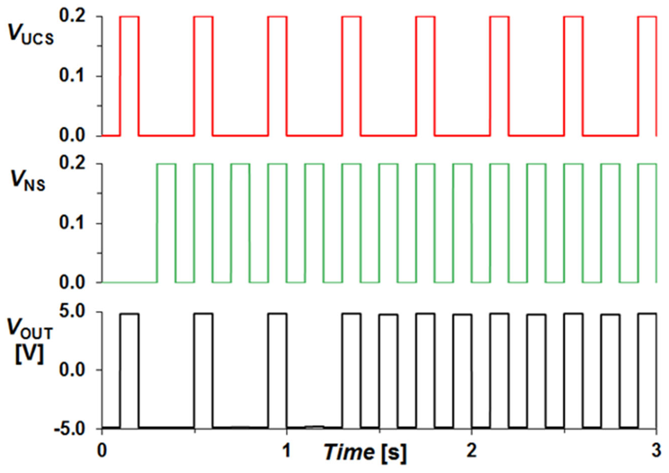
The high state of the signals UCS (Unconditional Stimulus) or NS (Neutral Stimulus) signifies the presence of food and the ringing of the bell in front of the dog, respectively. The circuit’s output corresponds to the dog’s drooling response. In
Figure 4, the simulation results depict scenarios where the high UCS signal represents multiple instances of food presentation. It is evident that the output remains consistently high for a high state of the UCS signal regardless of the NS signal’s state. After several instances where both the NS and UCS signals become high, the circuit begins to produce output even for the NS signal. This occurrence is attributed to continuous signal occurrences, which cause the memristance to decrease to a level where the comparator starts providing output even for the NS signal.
2.4. Issues with the Classical Circuit
As per the simulation results given in
Figure 4, the designed circuit appears to fully emulate the function of associative learning. However, upon closer examination, it is discovered that if the ring signal (NS) is presented without stimulating the UCS line, the output occurs after some instances (as depicted in
Figure 5). This is because the NS signal alone is sufficient to decrease the memristance of the memristor and elevate the compactor input above the reference voltage. It is akin to a dog starting to drool immediately after the bell rings. Additionally, in
Figure 6, it can be observed that even without presenting the food and ring together, a training fallacy is observed. After several pulses of the VUCS signal with NS being zero, the output also begins to occur for the NS signal with a UCS signal of zero.
2.5. Explanation of Training Fallacy
The training fallacy in the classical memristor-based associative learning circuit arises due to unintended changes in the memristor’s resistance state, leading to incorrect output activation. This results in false learning, where the circuit produces an output response (salivation) to the bell signal alone, even though no proper association with food was established. The memristor acts as a synaptic-like element, where its resistance state encodes learning; when food (UCS) and bell (NS) are presented together, the memristor’s resistance decreases, strengthening the connection between the stimuli and the output response. Ideally, this resistance should only decrease when both stimuli are applied together, simulating associative learning. However, the training fallacy occurs due to the cumulative nature of memristor resistance changes, leading to incorrect stimulus–response associations. Over multiple cycles, even when only the bell signal (NS) is applied repeatedly, small residual voltage differences across the memristor cause its resistance to slowly decrease, even in the absence of food (UCS). This unintended resistance reduction causes the memristor to eventually reach a threshold where an output is generated, even though true associative learning did not occur. The Op-Amp comparator in the classical circuit detects changes in memristance, and once the resistance drops below a certain threshold, it triggers an output, falsely indicating that learning has occurred. Since this resistance drop happens even when only the NS (bell) is applied, the circuit incorrectly learns an association that was never trained. This introduces a biological inaccuracy, as in Pavlov’s experiment the dog should only salivate when it has learned that the bell predicts food. However, in the classical circuit, the dog starts salivating simply because the bell was rung multiple times, even without pairing it with food. This contradicts biological learning principles, where associative learning requires a simultaneous pairing of stimuli, rather than repeated exposure to a single stimulus.
3. Proposed Improvement over the Existing Circuit
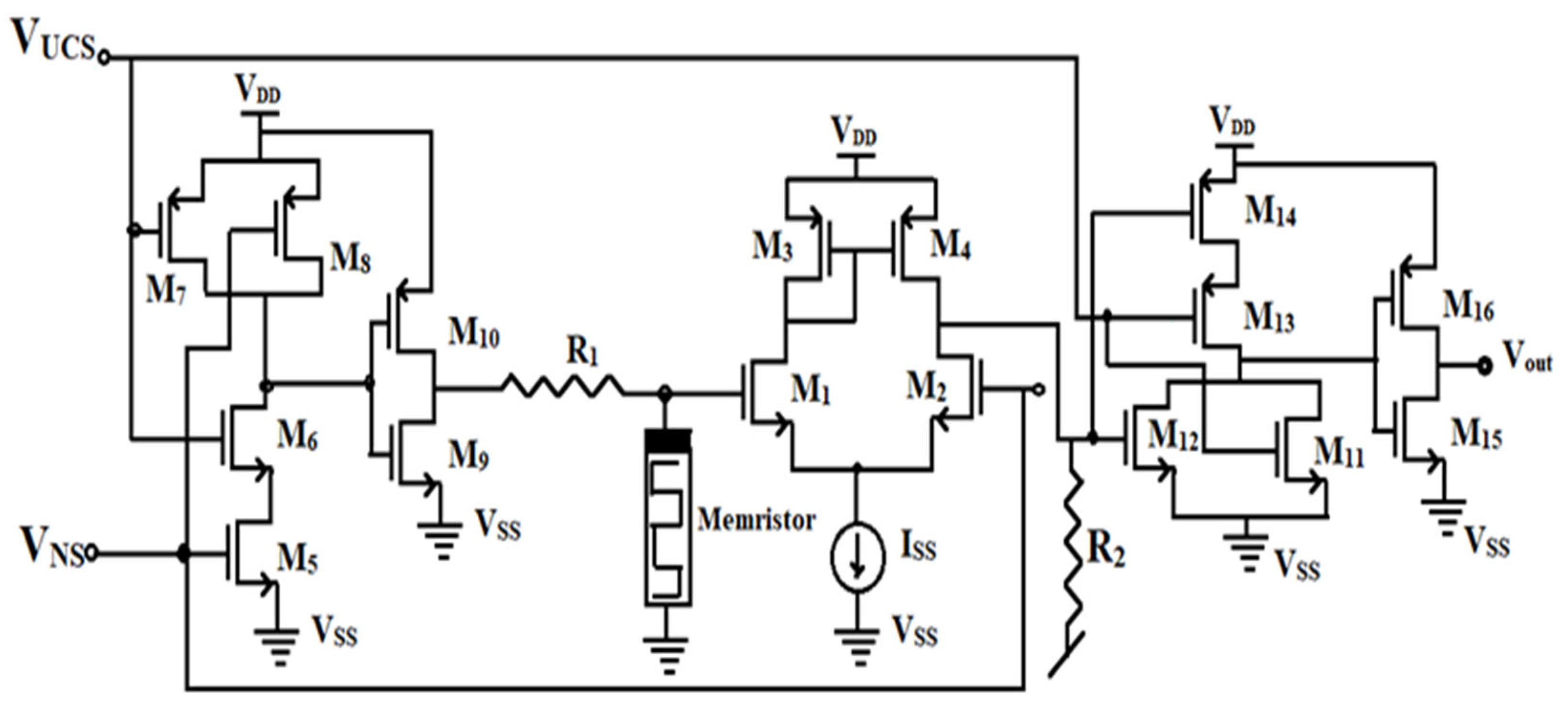
The proposed circuit has been provided in
Figure 7. It consists of sixteen CMOS transistors, which have been arranged to actually realize the functions of an OR gate, comparator, and the function of an AND gate. Unlike the classical circuit, the proposed circuit employs a grounded memristor. The functions of input signals UCS and NS are the same, which corresponding to the food and the bell signal, respectively, and the output emulates the drooling of the dog.
In the classical circuit, the dog starts salivating simply because the bell was rung multiple times, even without pairing it with food. This contradicts biological learning principles, where associative learning requires the simultaneous pairing of stimuli, rather than repeated exposure to a single stimulus. To address these issues, the proposed circuit incorporates CMOS-based logic gates (AND and OR) and a grounded memristor configuration, ensuring that the output is strictly triggered only when both UCS and NS are applied together. The AND gate enforces correct associative learning, while the OR gate allows the retrieval of trained responses, effectively eliminating false learning effects. Additionally, grounding the memristor prevents unintended resistance drift, ensuring long-term stability and accurate stimulus-response mapping, making the circuit more biologically realistic and robust.
3.1. Operation of the Proposed Improved Circuit
The operation of the associative learning circuit begins with the application of inputs V
UCS (Food) and V
NS (Bell). In the first stage, MOSFETs M5-M10 form an AND gate to detect stimulus pairing. If both inputs are high (conditioned stimuli detected), the circuit proceeds to the learning phase, otherwise, no output is generated. The memristor then modulates its resistance, decreasing over repeated cycles to mimic the learning process. Once the memristor reaches the learning threshold, the circuit activates the second transconductance stage (MOSFETs M1-M4) to amplify the signal for decision-making. In the final output decision stage, MOSFETs M11-M16 process the amplified signal and generate an output voltage V
out. If learning has been confirmed, the circuit produces a high V
out, indicating that the conditioned response (salivation) has been successfully simulated. The comparison of the classical circuit with the improved circuit is given in
Table 1.
3.2. Simulation Results of the New Circuit
The simulation outcomes have been generated to demonstrate the associative learning capability of the modified circuit as depicted in
Figure 7. For the proposed circuit simulations, resistance parameters were set as R1 = 10 k-Ohms and R2 = 100 k-Ohms, and the aspect ratios of the transistors are chosen as mentioned in
Table 2 along with the memristor parameters given in
Table 3. The memristor model and stimulation pulse periods remained the same as for the classical circuit simulations. The reasons for choosing the linear-ion drift model are as follows: The TiO
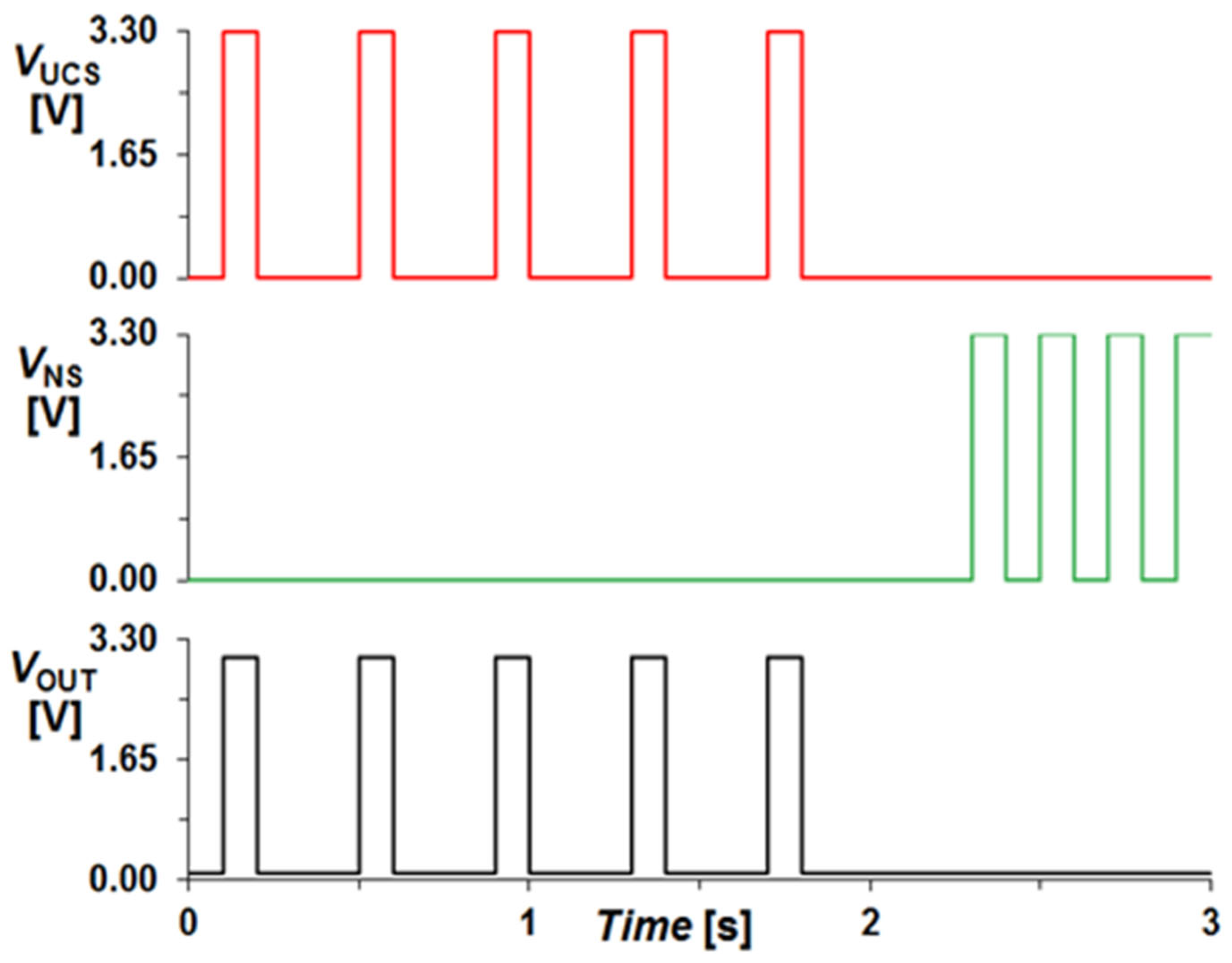
2-based nonlinear drift model was chosen because it closely mimics biological synapses, making it highly suitable for associative learning applications. The nonlinear ion drift dynamics accurately capture the resistance change observed in real memristors, ensuring a realistic hardware implementation. Threshold-based switching behavior aligns with classical conditioning requirements, where learning is established only after repeated co-activation of signals. It has been extensively validated in neuromorphic circuit simulations, making it a reliable choice for both software and hardware-based associative learning implementations. Moreover, all logic gates used in the proposed circuit are for 3.3 V logic; therefore, the input signals amplitude was set to 3.3 V and 0 V (for logical ‘1’ and ‘0’, respectively). The associative learning phenomenon of Pavlov’s experiment demonstrated by the circuit of
Figure 7 can be observed in the simulation results described in
Figure 8. These results are similar to the previously depicted results shown in
Figure 4. However, what distinguishes this redesigned circuit from its predecessor is its enhanced ability to precisely differentiate between the food and ring signals, as well as their simultaneous occurrences. As evident in
Figure 9, the output remains zero for the VNS signal, unlike in
Figure 6, as the circuit has not undergone training. Similarly, in
Figure 10, it can be observed that the output is never generated as long as the UCS signal remains zero, regardless of the frequency of the VNS signal occurrences.
The parameter values are chosen as per the following logic: The ON resistance (RON) of 1 kΩ ensures strong synaptic connections upon learning, where a higher value weakens the output signal, while a lower value increases current flow, risking noise interference. The OFF resistance (ROFF) of 100 kΩ prevents unwanted training effects and maintains memory retention, with a higher value slowing learning and a lower value causing false positive associations. The positive switching threshold (Vth+) of 5 V ensures that learning occurs only when both stimuli are present, preventing unintended switching at lower values, while higher values require stronger signals, delaying learning. The negative switching threshold (Vth−) of −1 V allows for the gradual forgetting of associations, where a lower value prevents forgetting, and a higher value leads to excessive memory loss, affecting long-term learning stability.
To assess the impact of parameter variations, a sensitivity analysis was conducted by modifying key parameters and observing changes in the learning behavior of the circuit. From this analysis, it was determined that optimal learning accuracy occurs when RON is low (~1 kΩ), ROFF is high (~100 kΩ), and Vth+ is sufficiently large (~5 V) to prevent erroneous associations. The results are discussed in
Table 4.
4. Validation of the Modified Circuit Using the Classical Circuit Memristor Emulator
In the previous section, we have performed PSPICE simulations using the memristor model discussed in
Section 2.2. Now, to validate the proposed circuit in hardware realizations, we have used a cheap replica of the real memristor called memristor emulator, that is based on an Integrator and transconductance amplifier. The block-level circuit idea of such a memristor emulation circuit is illustrated in
Figure 11. This emulator basically realizes the linear conductance model of the memristor, where the memductance depends linearly on the flux of the input voltage. The basic relationship of this memristor emulator can be given as follows:
where
.
The CMOS implementation of this idea is shown in
Figure 12. It comprises of less than 10 CMOS transistors and a grounded capacitance. The circuit realizes the expression of a flux-controlled memristor discussed in (3).
For the aspect ratios of the various transistors mentioned in
Table 5, pinched Hysteresis Loop (PHL), a key indicator of memristive behavior has been shown in
Figure 13. The loop is pinched at the origin, meaning that when zero voltage is applied, the current is also zero, confirming memory-dependent resistance changes. The two loops correspond to a High Resistance State (HRS) when the memristor is OFF and a Low Resistance State (LRS) when it is ON, mimicking synaptic plasticity in biological learning. The gradual reduction in resistance over repeated stimulus presentations suggests progressive learning and associative memory formation. The shrinking of the hysteresis loop at higher frequencies further validates the dynamic response of the memristor, aligning with theoretical models and confirming the accuracy of the memristor emulator used in this study.
Experimental Verification of the Proposed Associative Learning Modeling Circuit Using Commercially Available ICs
We have also verified the breadboard implementation of the proposed conditioning circuit using the classical OTA-based memristor emulator (of
Figure 11) given in
Figure 14. The memristor emulator has been implemented by developing the integrator stage using Op-Amp IC, µA741, and the IC LM13700 is used to simulate the function of a transconductance amplifier. The PHL plot of the realized memristor emulator is demonstrated on the DSO screen in
Figure 15. The data have been observed for the parameter values selected as: R1 = 10 k, RB = 30 k with capacitance value C
1 = 0.1 µF, along with the power supply voltages selected as ±V
CC = 12 V.
Now the proposed associative learning circuit has also been tested by using the IC-versions of an OR gate and AND gate, which are, respectively, ICs 7432 and 7408. Along with the breadboard implementation of the realized memristor emulator, the hardware implementation of the proposed associative learning circuit is tested, and the plotted transient responses are shown in
Figure 16 and
Figure 17, respectively. The inputs UCS and NS have been demonstrated in
Figure 16 and the output response is depicted in
Figure 17. It can be observed that output only shows itself for the bell signal once the food and bell signals are associated.
The following graph described in
Figure 18 portrays the inputs and output on a similar plot.


