Article

Model-Free Current Controller for PMSM Based on Super-Twisting Sliding Mode Observer

1
School of Electrical Engineering, Southeast University, Nanjing 210096, China
2
School of Intelligent Systems Engineering, Shaoxing University, Shaoxing 312000, China
*
Author to whom correspondence should be addressed.
Electronics 2025, 14(22), 4542; https://doi.org/10.3390/electronics14224542
Submission received: 30 October 2025 / Revised: 17 November 2025 / Accepted: 19 November 2025 / Published: 20 November 2025
(This article belongs to the Special Issue Modeling and Control of Power Converters for Power Systems)

Abstract

This paper proposes a super-twisting sliding mode observer-based model-free current controller (ST-MFCC) for permanent-magnet synchronous motor (PMSM). First, the mathematical model of the PMSM is established, and the model dependence of the deadbeat predictive current controller which serves as the foundation for the proposed ST-MFCC is analyzed, along with the stability impact of parameter variations on deadbeat predictive current control. Subsequently, the ST-MFCC is designed based on an ultralocal model and the super-twisting algorithm, eliminating dependence on the current model. Additionally, an adaptive method for tuning the key coefficients of the ultralocal model is introduced, enabling controller parameters to be rapidly optimized when deviations from actual system parameters occur. This approach reduces dependency on inductance parameters and aims to achieve high-performance PMSM current control with deadbeat characteristics. Finally, the effectiveness of the ST-MFCC is verified on a 400 W experimental platform.

1. Introduction

Permanent-magnet synchronous motors are widely used in electric vehicles, unmanned delivery vehicles, and deep-sea robots due to their high power density, high torque density, and high efficiency [1,2]. Based on the arrangement of internal permanent magnets, they can be mainly classified into two types: surface-mounted and interior-mounted [3].
As a classic motor controller structure, the speed-current double closed-loop control is built upon the control performance of the current loop. Typical current controllers include PI regulators, sliding mode controllers, model predictive control and deadbeat controllers [4,5,6,7,8,9]. Among these, the PI controller has a simple structure but its dynamic performance is limited due to coupling effects. The sliding mode controller exhibits strong robustness, but its sliding mode characteristics tend to cause chattering problems and its dynamic performance is difficult to improve. Model predictive control can conveniently incorporate various nonlinear factors and achieve a fast dynamic response. However, it suffers from pulsations, high computational load, unfixed switching frequency, torque ripple, and parameter sensitivity [8]. To address this issue, some studies have proposed a method combining SVPWM with a torque error cost function. However, due to the inclusion of two additional non-zero vectors, the computational load increases significantly [10]. Furthermore, to improve control performance under parameter errors, a scheme that incorporates the prediction error from the previous time step into the controller has been introduced. Although this method can reduce torque ripple, its suppression effectiveness is limited, and the dynamic performance has not been analyzed or considered [11].
As for the deadbeat predictive controller, it is more favored by researchers and employed in this paper due to its simple structure, high feasibility, and excellent dynamic performance [12]. The implementation process is as follows: First, the stator currents in the dq-axis are obtained through current sampling and transformation. Then, based on the discretized predictive current model, the optimal voltage vector is derived by combining the current reference values and sampled values. Finally, SVPWM is used to convert this into a PWM waveform, which enables the inverter to drive the motor, thereby achieving deadbeat current control. However, as mentioned above, since the design of the deadbeat predictive controller relies on the motor model and parameters, its steady-state accuracy, dynamic performance, and stability are all limited by the accuracy of the model and parameters. Parameter mismatches can degrade controller performance. To reduce parameter dependence, the literature [13] proposes an Extended State Observer (ESO) to estimate and compensate for total disturbances caused by parameter mismatches, and predicts the next-sample current value through the observer to enhance the controller’s dynamic performance.
Similar methods include the Luenberger observer [14] and the sliding mode observer [15]. Although these methods can reduce parameter dependence, they still require motor models and parameters, they have limited tolerance for model and parameter mismatches, and their robustness remains insufficient.
In order to reduce the dependency of motor control performance on parameters, model-free control methods have gradually attracted the attention of scholars. A typical example is the adaptive model-free control strategy proposed in [16]. However, this paper primarily focuses on model-free control of the mechanical parameters, with limited discussion on the current loop. In terms of the current loop, ref. [17] proposes a model-free control strategy based on deep learning theory. By leveraging deep learning, the method effectively estimates and compensates for model errors, thereby enhancing the stability of the current loop. However, this approach suffers from high computational complexity. To further reduce the dependency on current loop parameters and computational complexity, refs. [18,19] designed current controllers based on the ultralocal model [20]. The ultralocal model uses a general differential equation to replace the motor model, which can effectively reduce the controller’s dependence on the model. It is worth mentioning that the ultralocal model has also been applied to islanded AC microgrids, where it is used to model LC filters for enhancing the robustness of grid frequency and voltage [21].
Among them, [18], combined with the ultralocal model, adopts an algebraic method to observe unmodeled disturbances in the model. This method involves a complex disturbance estimation process, and its accuracy is severely affected by sampling frequency and sampling precision, resulting in poor anti-interference performance for sampling. In addition, ref. [19] designed a sliding mode observer (SMO) to observe disturbances.
The sliding mode observer can reduce dependence on sampling and exhibits stronger robustness. Similar applications are commonly found in power systems; for instance, ref. [22] employs a sliding mode observer to enhance grid stability. However, due to the existence of the sliding mode surface, the system inevitably experiences chattering, thereby limiting its performance.
Moreover, the coefficient tuning of the above model-free current controllers, whether using the algebraic method or the sliding mode observer method, directly uses inductance parameters, which to some extent increases the dependence on motor parameters.
To this end, this paper proposes a model-free current controller for PMSMs, with the main contributions as follows:
  • An ultralocal model is adopted to replace the traditional motor model, enabling model-free deadbeat control without relying on the motor model;
  • An observer based on the super-twisting sliding mode algorithm is designed to estimate disturbances and predict currents, thereby enhancing the dynamic performance of current control and improving robustness to variations in electromagnetic parameters;
  • A coefficient-adaptive method based on deadbeat current tracking is proposed to ensure rapid optimization when controller coefficients deviate from actual parameters, thereby eliminating dependence on inductance parameters.

2. Modeling of the PMSM

The voltage model of the PMSM under the dq-axis can be represented as:
u d = R m i d L m ω i q + L m p i d u q = R m i q + L m ω i d + L m p i q + ψ m ω e
where u and i are the voltage and current, the subscript dq indicates the dq-axis, ωm is the mechanical angular speed, Lm, R, and ψm are the inductance, stator resistance, and permanent-magnet flux linkage, the subscript m indicates the actual motor parameter, and p indicates a differential operator.
Consistent with conventional control methods, this paper also employs SVPWM to generate the duty cycle. However, due to the limitations of the digital signal processor, the update of the duty cycle causes a one-period delay in sampling and calculation, as shown in Figure 1, which illustrates the timing diagram of sampling, calculation, and PWM loading; therefore, the dq-axis current differential equations of the PMSM can be derived by the Euler method s = ((z − 1)/Ts) as:
i d k + 1 = 1 R m T s L m i d k + ω e T s i q k + T s L m u d k 1 i q k + 1 = 1 R m T s L m i q k ω e T s i d k + T s L m u q k 1 T s ω e ψ m L m
where k represents the control time step and Ts represents the control period.

3. Traditional Deadbeat Predictive Current Controller

In the conventional deadbeat predictive current control, to compensate for the delay caused by the digital control system, the current value at time step k + 1 is typically predicted based on (2) as:
i d k + 1 = 1 R c T s L c i d k + ω e T s i q k + T s L c u d k 1 i q k + 1 = 1 R c T s L c i q k ω e T s i d k + T s L c u q k 1 T s ω e ψ c L c
where the subscript c represents the parameter used in the current controller.
As analyzed above, k-th interval sampling currents are induced by (k − 1)-th reference voltages; hence, (k + 1)-th predictive currents are always used to calculate reference voltages at the k-th interval to realize the current control as:
u d ( k ) = L c T s i d ( k + 2 ) ω e L c i q ( k + 1 ) ( L c T s R m ) i d ( k + 1 ) u q ( k ) = L c T s i q ( k + 2 ) + ω e L c i d ( k + 1 ) ( L c T s R m ) i q ( k + 1 ) + ω e ψ c
where the current at time k + 2 is replaced by the reference current, i.e., idq(k + 2) = idq(ref). However, the traditional deadbeat predictive current controller relies too much on the motor model and motor parameters, resulting in its dynamic and steady-state performance as well as its stability being dependent on the accuracy of the model and parameters. To illustrate this situation more precisely, the current closed-loop transfer function considering parameter adaptation is given as follows:
i d q = L c L m z 2 + L c L m 1 j ω e T s 2 1 j ω e T s 2 i d q r e f + z 1 T s L m ω e 2 T s + j 2 ω e T s L m z 2 + L c L m 1 j ω e T s 2 1 j ω e T s 2 ψ c ψ m
Further, based on (5), and taking the inductance parameter, which has the most significant impact on the system, as an example, the pole distribution diagrams under different parameter errors are presented in Figure 2. It can be observed from the figure that
  • When the controller inductance parameter is smaller than the actual inductance, the closed-loop poles deviate from the origin, resulting in a stable system but with degraded dynamic performance;
  • When the controller inductance parameter is larger than the actual inductance, as the rotational speed increases, the closed-loop poles move closer to the boundary, leading to deteriorating stability;
  • When the inductance parameter error exceeds twice the actual value, the system becomes unstable.
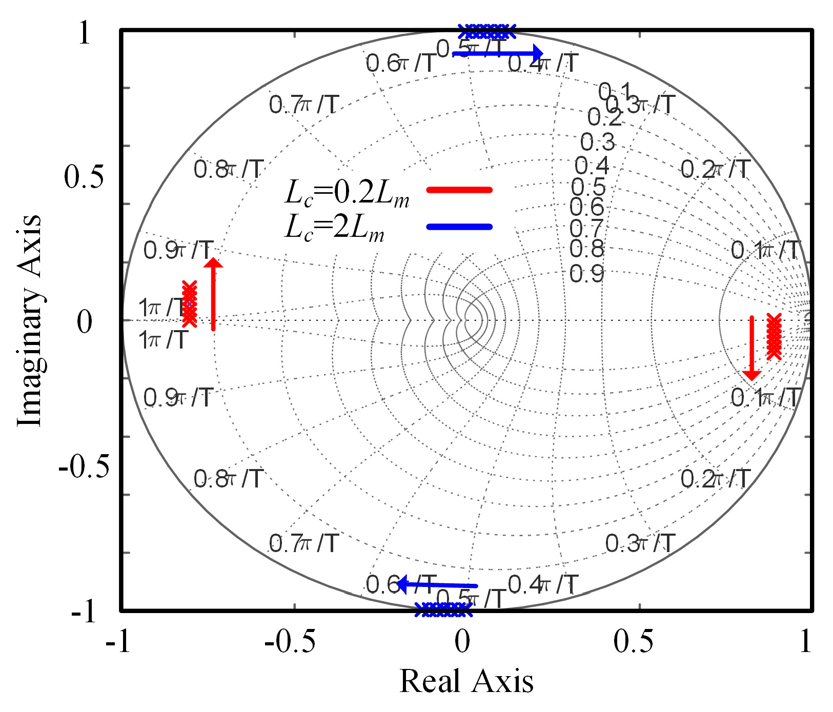
Figure 2. Pole distribution diagrams under different parameter errors.
Electronics 14 04542 g002

4. Proposed ST-MFCC

To address the aforementioned issues, this paper proposes a model-free current control strategy that combines an ultralocal model with a super-twisting sliding mode observer. This approach eliminates reliance on the PMSM voltage model while reducing the computational burden associated with unmodeled disturbance observation and enhancing both robustness and accuracy. Furthermore, a model coefficient adaptation strategy is incorporated to further improve robustness against PMSM parameter variations.

4.1. MFCC

To shape the unknown ‘complex’ mathematical model, an ultralocal model is proposed as [18]:
p v y = F + α m u
where v is the order of the model, αm is the model gain, and F denotes the total perturbance. According to the ultralocal model shown above, the current differential equations of the PMSM are derived as:
i d ( k + 1 ) = i d ( k ) + T s F d ( k ) + α m T s u d ( k 1 ) i q ( k + 1 ) = i q ( k ) + T s F q ( k ) + α m T s u q ( k 1 )
This shows that the initiation of the model gain αm can be selected as L m 1 , and Fd(k) = −Rm L m 1 id(k) + ωeiq(k), Fq(k) = −Rm L m 1 iq(k) − ωeid(k) − L m 1 ωeψm. Likewise, by considering the digital signal processor delay, the MFCC based on the ultralocal model can be deduced as:
u d ( k ) = ( α m T s ) 1 [ i d ( ref ) i d ( k + 1 ) ] α m 1 F d ( k + 1 ) u q ( k ) = ( α m T s ) 1 [ i q ( ref ) i q ( k + 1 ) ] α m 1 F q ( k + 1 )

4.2. Super-Twisting Sliding Mode Observer

According to (8), the implementation of the MFCC relies on the prediction accuracy of idq and Fdq at the (k + 1)-th interval. Furthermore, considering the robustness of the SMO and the problem of traditional sliding mode chattering, the SMO based on the super-twisting algorithm (STA) is designed to predict idq(k + 1) and Fdq(k + 1) to realize model-free current control, in which the STA is proposed by Levant [23] and its basic form is
p x 1 = k 1 | x 1 | 0.5 s i g n ( x 1 ) + x 2 + ρ 1 ( x , t ) p x 2 = k 2 s i g n ( x 1 ) + ρ 2 ( x , t )
where xi denote state variables, ki are the coefficients, ρi are perturbation terms, and sign is the sign function. Moreover, Moreno et al. in [24] proved that the observer (9) is stable when its perturbation terms are globally bounded by | ρ 1 | δ 1 | x 1 | 0.5 , ρ 2 = δ 1 ( δ 1 , δ 2 + ) , and its sliding mode coefficients satisfy the conditions
k 1 > 2 δ 1 , k 2 > k 1 5 δ 1 k 1 + 6 δ 2 + 4 ( δ 1 + k 1 1 δ 1 ) 2 2 ( k 1 2 δ 1 )
Following (9), the observer for predicting perturbances and currents based on STA is designed as:
p i d q p r e = α m u d q + k 1 | i d q e r r | 0.5 s i g n ( i d q e r r ) + F d q p r e p F d q p r e = k 2 s i g n ( i d q e r r )
Before deducing the error differential equation, the ultralocal model (7) is represented and the differential equation of disturbance Fdq is added
p i d q = F d q + α u d q p F d q = f d q
Then, according to the observer (11) and ultralocal model (12), the error differential equation is
p i d q e r r = k 1 | i d q e r r | 0.5 sign ( i d q e r r ) + F d q e r r p F d q e r r = f d q k 2 sign ( i d q e r r )
When the error in (13) converges to zero, the discrete (k + 1)-th prediction values of currents and disturbances are:
i d q p r e ( k + 1 ) = i d q p r e ( k ) + α m T s u d q ( k 1 ) + T s k 1 | i d q e r r ( k ) | 0.5 sign ( i d q e r r ( k ) ) + T s F d q e r r ( k + 1 ) F d q p r e ( k + 1 ) = F d q e r r ( k ) + T s k 2 sign ( i d q e r r )
Then, the model-free deadbeat controller is designed as:
u d q ( k ) = ( α m T s ) 1 [ i d q ( ref ) i d q p r e ( k + 1 ) α m 1 F d q p r e ( k + 1 )
Stability Proof: From (11), it can be seen that ρ1(x, t) = 0, ρ2(x, t) = fdq, large enough δ1 and δ2 can be easily selected to satisfy boundary condition, and finally k1 and k2 can be set from (10). In addition, as mentioned above, αm is essentially the reciprocal of inductance. To eliminate the reliance of the current controller on motor parameters, the adaptive algorithm based on the deadbeat characteristic in [3] is used.

4.3. Adaption of the Coefficient

As mentioned above, the key coefficient of the designed model-free controller is essentially the inverse of the inductance, so it still depends on the PMSM parameters to some extent. To address this issue, this paper proposes a parameter adaptation strategy that combines the deadbeat characteristic shown in Table 1 with a bang-bang controller. This strategy ensures the deadbeat control of the current loop, meaning that the current at time step k + 2 tracks the reference value set at time step k.
To implement this parameter adaptation, an analysis of the current values during deadbeat control is first conducted. The following table presents the key variable values at several adjacent time steps in the deadbeat predictive current controller.
As can be observed from the table, when deadbeat current control is adopted, the sampled current value at time step k + 2 is related to the accuracy of the key coefficient α, and is positively correlated with the error between the controller parameter αc and the actual parameter αm. Specifically
  • When αc is greater than αm, the sampled current at k + 2 exceeds the reference value at k, resulting in overshoot;
  • When αc is less than αm, the sampled current at k + 2 is less than the reference value at k, preventing fast tracking;
  • When and only when αc equals αm, the sampled current at k + 2 equals the reference value at k, achieving deadbeat current control.
Therefore, a parameter adaptation rule is proposed by combining this deadbeat characteristic with a bang-bang controller as follows:
α c = k α sign i d ref i d k + 2
where kα is the coefficient of the α adaptive adaptation strategy. Thus, the proposed ST-MFCC can achieve deadbeat predictive current control under arbitrary operating conditions, featuring advantages of model independence, parameter independence, strong robustness, and fast dynamic performance.
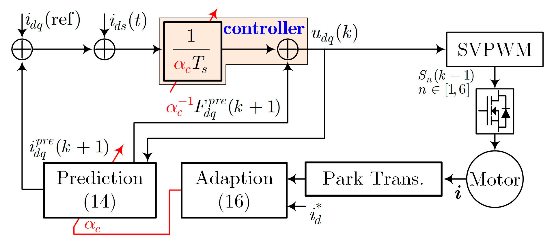
To facilitate a better understanding of the application of the proposed method in this paper, a control block diagram is provided in Figure 3. It primarily consists of a controller, prediction module, adaptive module, and the plant. The control procedure is as follows: First, the three-phase currents of the motor are sampled and transformed into dq-axis-sampled currents via the Park transform. Subsequently, based on the injected auxiliary current signal in the d-axis and the sampled signals, the coefficient αc is adaptively updated according to (16). Then, the observer, as given in (14), is utilized to predict the current and unmodeled disturbances for the next time step. Finally, the controller computes the optimal voltage vector for the current period, which is converted via SVPWM into chopped signals to drive the inverter, thereby supplying power to the motor and completing the motor control process.
It is worth mentioning that the method proposed in this paper also has certain limitations. Its parameter adaptation process relies on (16), and to obtain sufficient information for parameter adaptation, a continuous signal needs to be injected into the d-axis, which will cause slight additional losses. However, the amplitude of the auxiliary signal injected into the d-axis is extremely small, only 0.1 A. Moreover, considering that the d-axis does not produce torque pulsations, injecting such a minimal signal into the d-axis does not affect motor performance, while significantly enhancing the robustness of the current loop against parametric variations.

5. Experimental Results

5.1. Introduction to the Experimental Platform

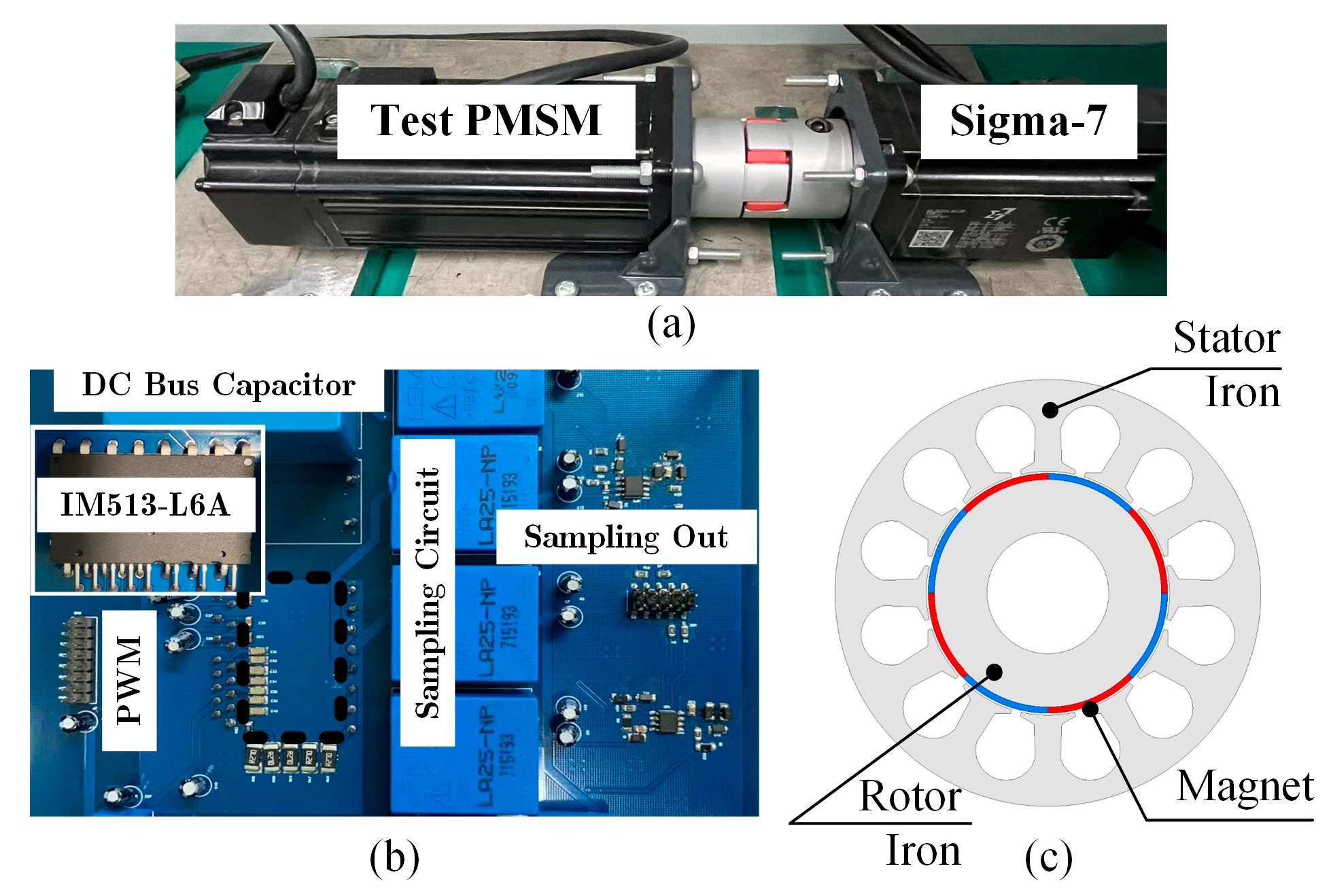
An experimental study is carried out to assess the proposed algorithm, using the test bench illustrated in Figure 4, and the main parameters of the platform are shown in Table 2. This setup comprises two main components: the motor system and the control unit. The motor system features two 400 W permanent-magnet synchronous motors. The test motor is a commercial motor, adopting a surface-mounted PMSM structure with four pole pairs. Since it is a commercial motor and its internal structure cannot be obtained, a typical surface-mounted PMSM structure with four pole pairs is provided here, as shown in Figure 4c. Additionally, its stator resistance is 1.6 Ω, inductance is 9 mH, and flux linkage is 0.006 Wb. Moreover, A YASKAWA Sigma-7 motor from Yaskawa Electric Corporation, Kitakyushu, Japan, serves as the load motor, responsible for speed regulation during the current loop performance evaluation.
The control unit integrates both drive and sensing circuitry. The power stage utilizes an Infineon IM513-L6A intelligent power module from Infineon Technologies AG, Neubiberg, Germany configured in a conventional two-level voltage source inverter topology. Voltage and current measurements are acquired using LV25-P and LA25-NP sensors, respectively. The control algorithm runs on a TMS320F28335 microcontroller with a PWM switching frequency of 10 kHz.

5.2. Experimental Comparison

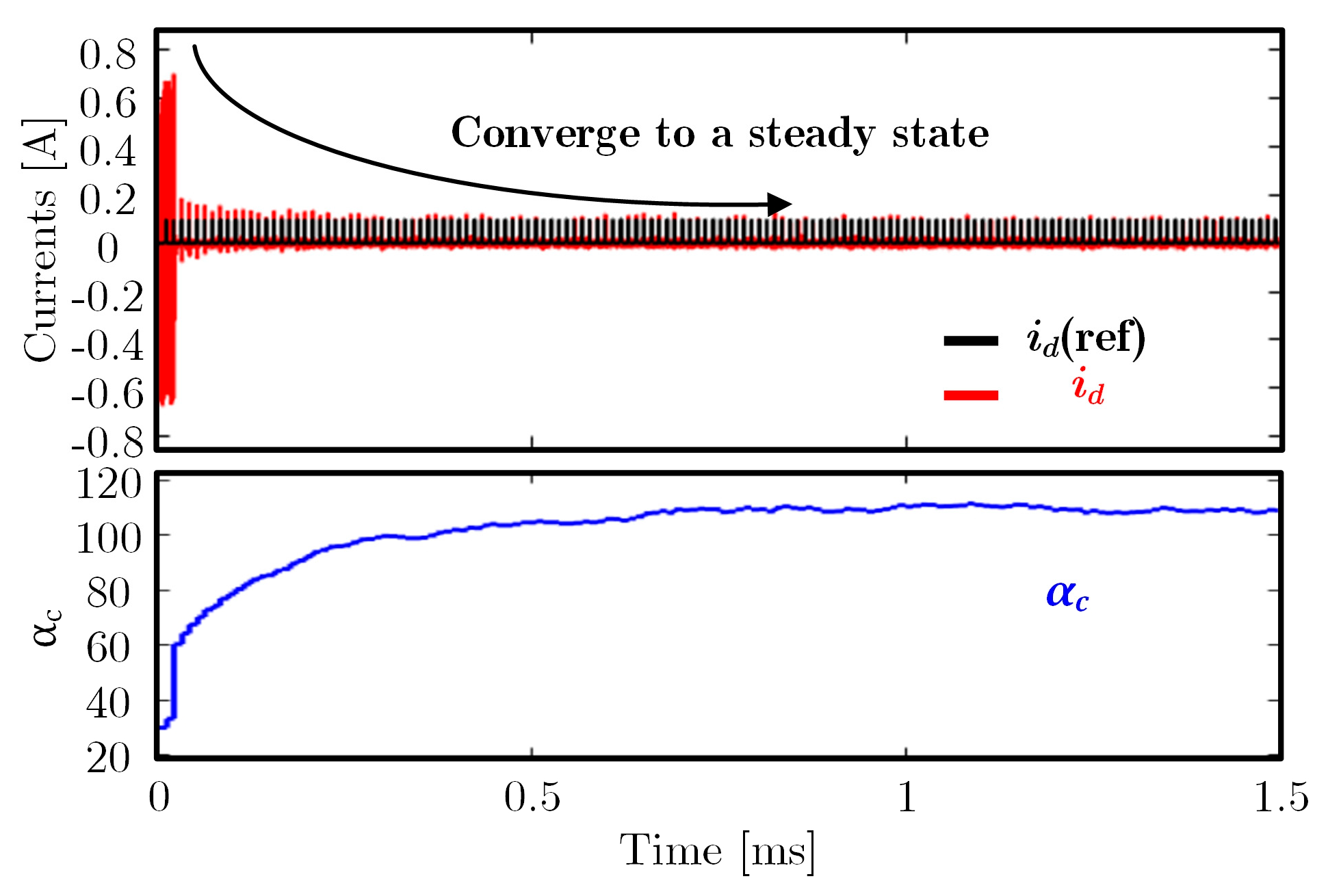
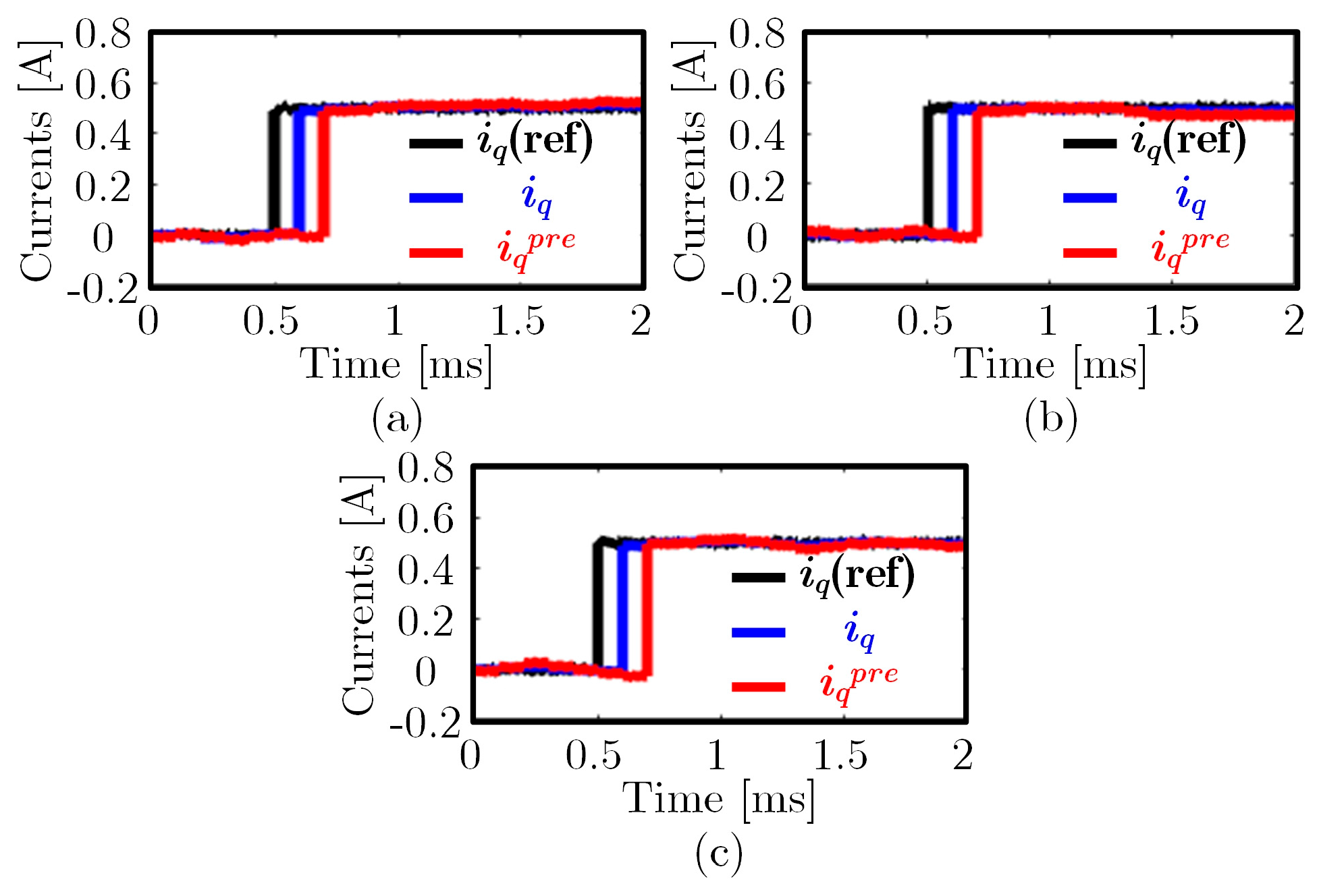
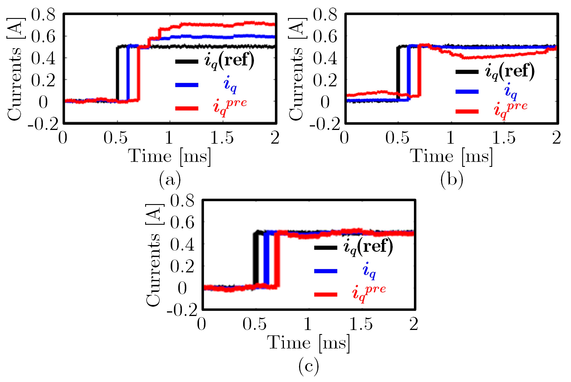
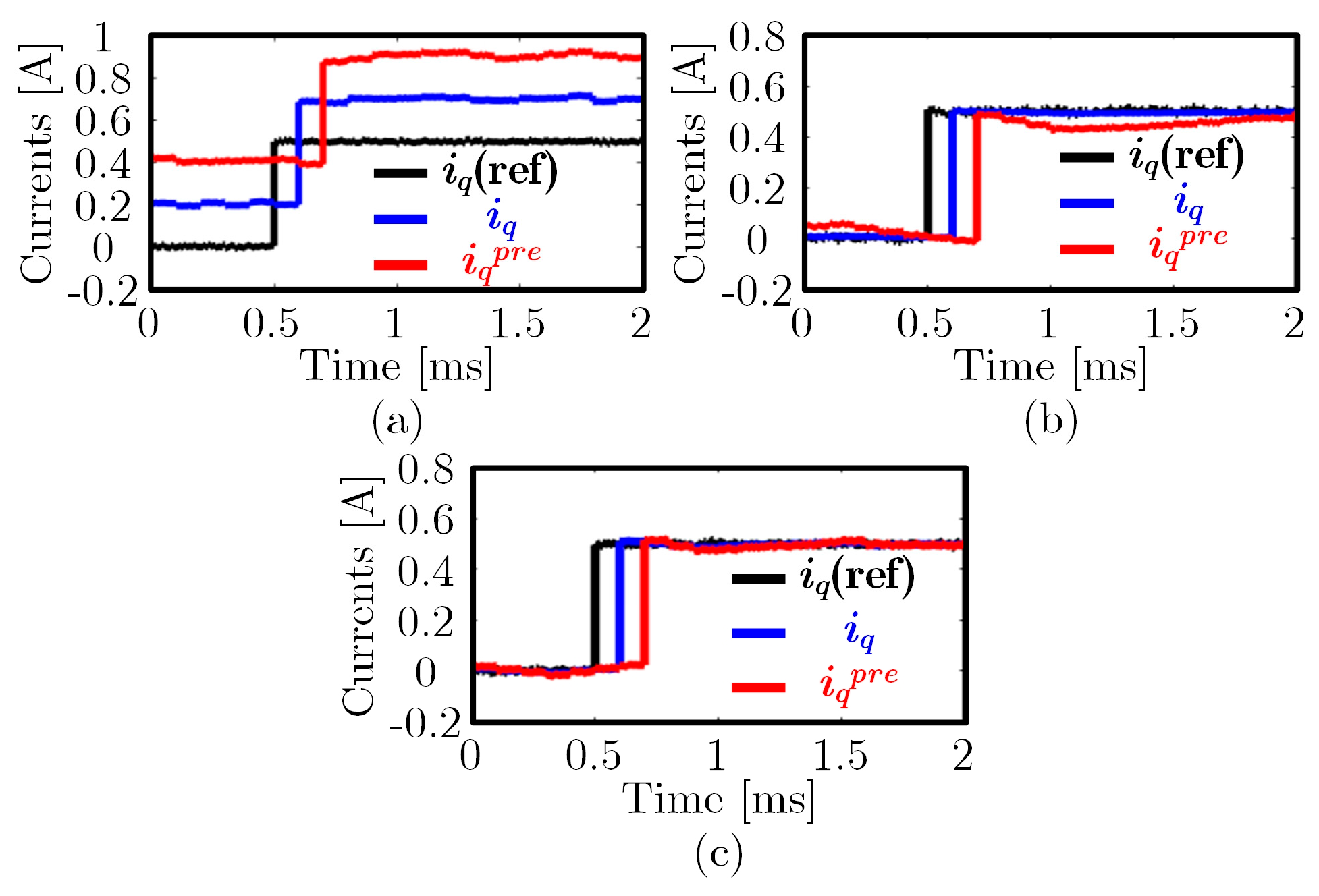
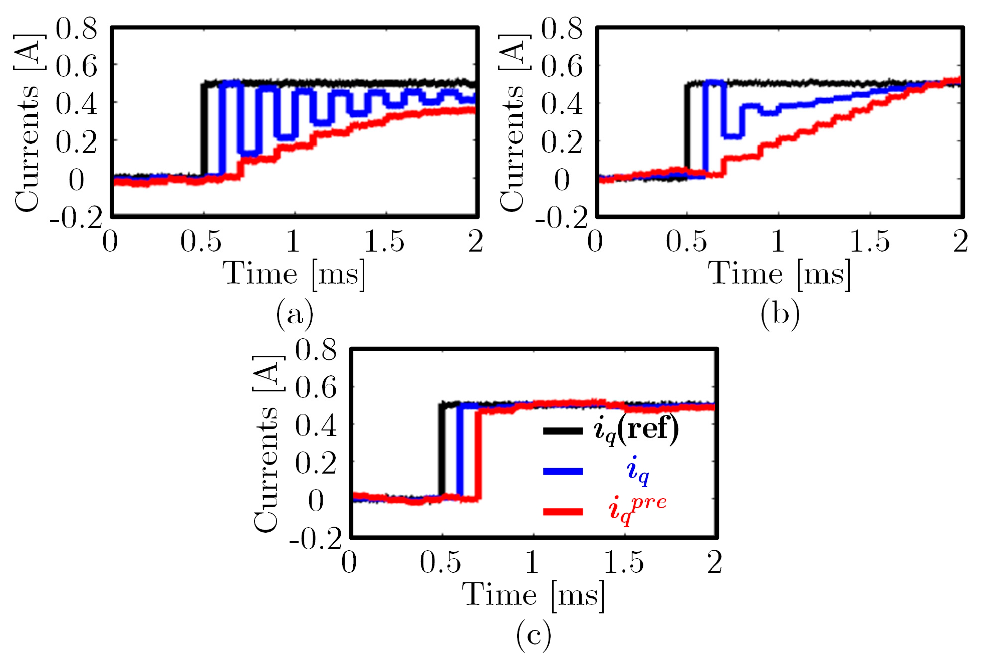
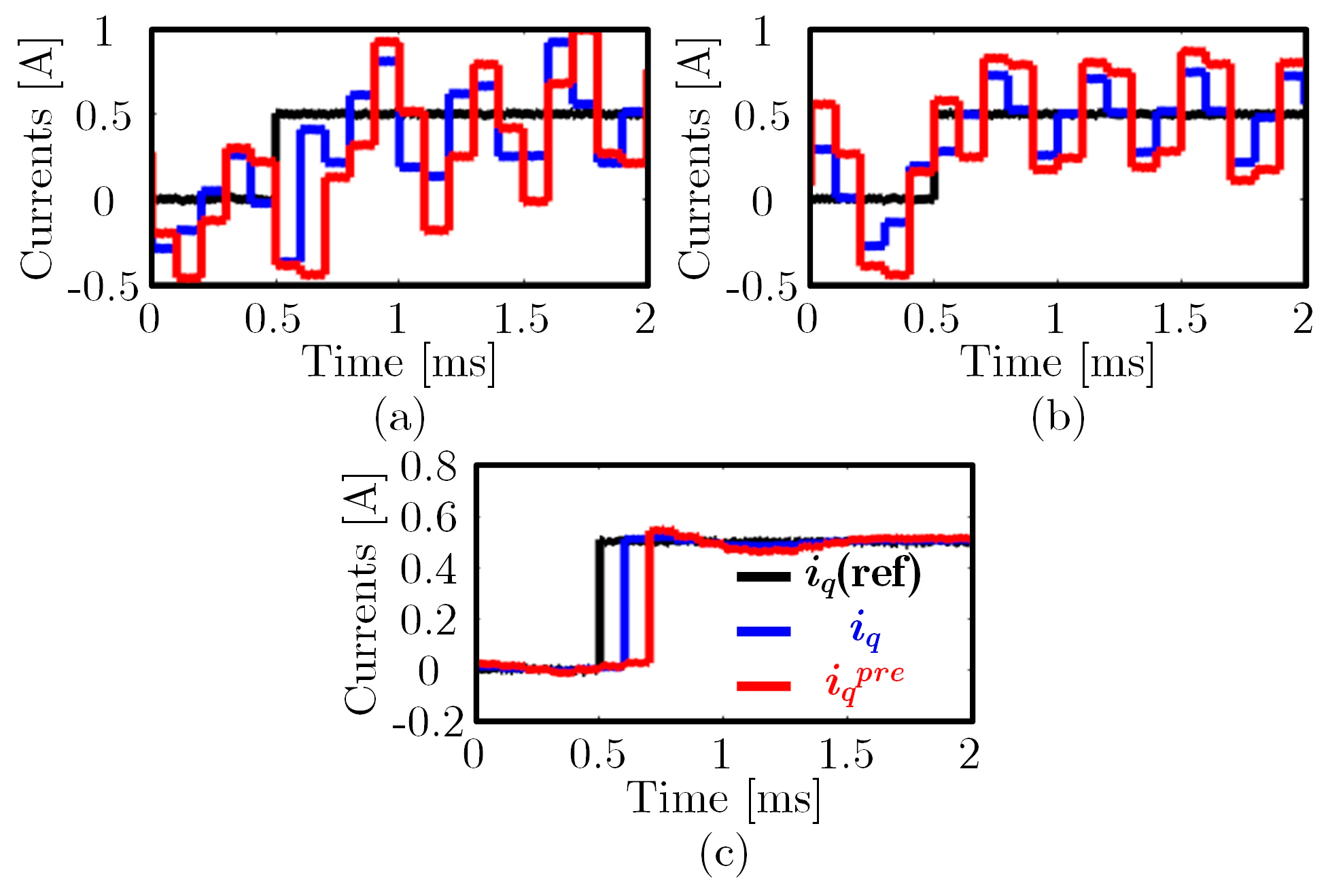
To verify the convergence, dynamic, and robust performance of the proposed ST-MFCC, this paper presents experimental results of step responses comparing the traditional DPCC, SMO-DPCC, and ST-MFCC under various parameter conditions. Figure 5, Figure 6, Figure 7, Figure 8, Figure 9 and Figure 10 illustrate the coefficient convergence, the step response comparisons without parameter error, the step response comparisons with parameter error, and the step response comparisons under step changes in parameters, respectively.
Figure 5 illustrates the parameter adaptation process of the proposed ST-MFCC algorithm during the start-up phase, where the initial parameter value is set to 30. It can be observed that at the initial start-up stage, since the set controller inductance value is nearly 4 times larger than the actual value, the system exhibits severe oscillations, which can also be concluded from the current waveforms. However, as the parameter adaptation algorithm based on deadbeat characteristics converges, the controller inductance value gradually approaches the actual value, and the oscillation phenomenon during the current step process gradually diminishes. Eventually, when the coefficient converges to the deadbeat value, the current achieves optimal control performance.
Figure 6 presents the experimental comparison results under the condition of no parameter mismatch, showing the waveforms of q-axis reference current, predicted current, and sampled current. In the absence of parameter errors, all three algorithms exhibit high dynamic response capability and steady-state accuracy. Moreover, compared with MFCC, SMO-DPCC has obvious chattering. However, the proposed ST-MFCC, which adopts a high-order sliding mode observer, can effectively suppress the chattering problem, resulting in smaller chattering in the q-axis current. In general, the three algorithms show little difference when there is no parameter error, and all possess good current control performance.
Further experimental comparisons are conducted which are illustrated in Figure 7 under parameter mismatch conditions, starting with the case where the controller resistance parameter is set to ten times its actual value. The results indicate that the conventional DPCC exhibits a significant DC offset due to the large resistance error, whereas the SMO-DPCC can compensate for the effects caused by the resistance mismatch through its sliding mode observer, albeit at the cost of some dynamic performance. In contrast, the proposed ST-MFCC, being model-independent, remains unaffected by resistance variations in the model and thus maintains excellent step response performance.
Similarly, the experimental results for the case where the controller flux linkage parameter is set to ten times the actual value are presented in Figure 8. Since both resistance and flux linkage have similar effects on the current loop, both can cause DC offset issues. Consequently, the experimental results shown in Figure 8 are similar to those in Figure 7, with the proposed ST-MFCC continuing to demonstrate the best control performance among the three methods.
Further experiments are conducted to verify the effects of inductance parameter errors, which have the most significant impact on the current loop. Figure 9 presents the experimental results when the controller inductance is set to 0.2 times the actual value. As shown in the figure, while the conventional DPCC avoids instability despite the underestimated inductance value, its dynamic performance deteriorates sharply. The SMO-DPCC faces the same issue due to its lack of coefficient adaptation capability. In contrast, the proposed ST-MFCC, through its coefficient adaptation mechanism, can adjust the controller parameters from initial values lower than the actual parameters to the correct values, ensuring deadbeat current tracking and achieving the best current control performance among the three methods.
The periodic delay between the given, predicted, and actual values shown in Figure 7, Figure 8 and Figure 9 is caused by the PWM loading delay mentioned in Figure 1. The DPCC method adopted in this paper has reduced the delay between the actual and predicted values to the theoretical minimum of two cycles through prediction. As shown, when there are errors in the resistance and flux linkage parameters, traditional DPCC exhibits a DC bias due to parameter errors, a conclusion that can be verified in (5). However, when there are errors in the inductance parameters, traditional DPCC does not exhibit a DC bias but only experiences a reduction in dynamic performance, eventually converging to the given value. This point can also be explained by the pole trajectory shown in Figure 2.
Additionally, the experimental results with the controller inductance parameter set to three times the actual value are presented in Figure 10. As shown in the figure, the conventional DPCC system becomes unstable due to the excessive inductance parameter error, resulting in severe oscillations in the current waveform. While the SMO-DPCC inherently possesses a certain degree of robustness, it fails to fully compensate for the disturbance factors caused by parameters under the given operating condition with excessive inductance error, thus also exhibiting significant oscillations in its current response waveform. In contrast, the ST-MFCC proposed in this paper, with its excellent parameter adaptation capability, can maintain stability even under the condition of threefold inductance error.
Finally, to provide a clearer comparison of the performance of the three algorithms, a quantitative performance comparison table is presented as shown in Table 3, evaluating their step response performance under different parameter errors. When no parameter errors exist, the performance of all three algorithms is similar, and each can achieve deadbeat current control. When there is a 10 times error in the resistance and flux linkage parameters, the conventional DPCC fails to achieve deadbeat control due to the presence of DC bias, while both the SMO-DPCC and ST-MFCC still maintain deadbeat control performance. When the controller inductance is set to 0.2 times the actual inductance, the dynamic response of the conventional DPCC deteriorates significantly, requiring over 15 control cycles to settle. The SMO-DPCC also needs nearly 15 cycles to track the reference, whereas the proposed ST-MFCC can track the reference within just 2 cycles. When the controller inductance is set to 3 times the actual inductance, both the conventional DPCC and SMO-DPCC become unstable. In contrast, the proposed algorithm remains stable and continues to achieve deadbeat current control, demonstrating its effectiveness.

6. Conclusions

This paper proposes an ST-MFCC for PMSM based on a super-twisting sliding mode observer. By combining an ultralocal model with a coefficient adaptation mechanism, the proposed controller effectively addresses the high parameter sensitivity issue of traditional deadbeat predictive current control. Experimental results on a 400 W platform demonstrate that, compared with conventional DPCC and SMO-DPCC, the ST-MFCC exhibits superior dynamic response, enhanced robustness, and better steady-state performance under conditions such as parameter mismatch and step changes, verifying its effectiveness and practicality.

Author Contributions

Conceptualization, J.C.; methodology, Y.W.; software, Y.W.; validation, Y.W.; writing—original draft preparation, Y.W.; writing—review and editing, Y.W.; visualization, Y.W.; supervision, J.C.; project administration, J.C.; funding acquisition, J.C. All authors have read and agreed to the published version of the manuscript.

Funding

This research and the APC were funded by the Zhejiang Provincial Natural Science Foundation of China, grant number LQN25E070003, and the National Natural Science Foundation of China, grant number 62403324.

Data Availability Statement

The original contributions presented in this study are included in the article. Further inquiries can be directed to the corresponding author.

Conflicts of Interest

The authors declare no conflicts of interest.

References

  1. Johnson, M.; Gardner, M.C.; Toliyat, H.A. Design and Analysis of an Axial Flux Magnetically Geared Generator. IEEE Trans. Ind. Appl. 2017, 53, 97–105. [Google Scholar] [CrossRef]
  2. Ito, K.; Nakamura, K. Investigation of Magnetic Interaction of IPM-Type Magnetic-Geared Motor. IEEE Trans. Magn. 2021, 57, 8202005. [Google Scholar] [CrossRef]
  3. Chen, J.; Fan, Y.; Cheng, M.; Zhang, Q.; Chen, Q. Parameter-Free Ultralocal Model-Based Deadbeat Predictive Current Control for PMVMs Using Finite-Time Gradient Method. IEEE Trans. Ind. Electron. 2023, 70, 5549–5559. [Google Scholar] [CrossRef]
  4. Rodriguez, J.; Kennel, R.M.; Espinoza, J.; Trincado, M.; Silva, C.A.; Rojas, C.A. High-Performance Control Strategies for Electrical Drives: An Experimental Assessment. IEEE Trans. Ind. Electron. 2012, 59, 812–820. [Google Scholar] [CrossRef]
  5. Chen, J.; Fan, Y.; Wang, W.; Lee, C.H.T.; Wang, Y. Sensorless Control for SynRM Drives Using a Pseudo-Random High-Frequency Triangular-Wave Current Signal Injection Scheme. IEEE Trans. Power Electron. 2022, 37, 7122–7131. [Google Scholar] [CrossRef]
  6. Wang, Y.; Feng, Y.; Zhang, X.; Liang, J. A New Reaching Law for Antidisturbance Sliding-Mode Control of PMSM Speed Regulation System. IEEE Trans. Power Electron. 2020, 35, 4117–4126. [Google Scholar] [CrossRef]
  7. McNabb, L.; Wang, L. An Improved Horizon-1 Finite-Control-Set Model-Predictive Current Control Design for an Induction Machine with Integrated Anti-Windup. IEEE Trans. Control Syst. Technol. 2023, 31, 985–988. [Google Scholar] [CrossRef]
  8. Rodriguez, J.; Kazmierkowski, M.P.; Espinoza, J.R.; Zanchetta, P.; Rub, H.A.; Young, H.A. State of the Art of Finite Control Set Model Predictive Control in Power Electronics. IEEE Trans. Ind. Inform. 2013, 9, 1003–1016. [Google Scholar] [CrossRef]
  9. Wang, Y.; Liao, W.; Huang, S.; Zhang, J.; Yang, M.; Li, C.; Huang, S. A Robust DPCC for IPMSM Based on a Full Parameter Identification Method. IEEE Trans. Ind. Electron. 2023, 70, 7695–7705. [Google Scholar] [CrossRef]
  10. Zhang, Y.; Yang, H. Two-Vector-Based Model Predictive Torque Control Without Weighting Factors for Induction Motor Drives. IEEE Trans. Power Electron. 2016, 31, 1381–1390. [Google Scholar] [CrossRef]
  11. Siami, M.; Khaburi, D.A.; Rodriguez, J. Torque Ripple Reduction of Predictive Torque Control for PMSM Drives with Parameter Mismatch. IEEE Trans. Power Electron. 2017, 32, 7160–7168. [Google Scholar] [CrossRef]
  12. Fang, Y.; Chen, J. Improved Model-Free Deadbeat Predictive Current Controller for PMSMs Based on Ultralocal Model and H∞ Norm. Energies 2024, 17, 2649. [Google Scholar] [CrossRef]
  13. Zhang, Q.; Fan, Y.; Mao, C. A Gain Design Method for a Linear Extended State Observers to Improve Robustness of Deadbeat Control. IEEE Trans. Energy Convers. 2020, 35, 2231–2239. [Google Scholar] [CrossRef]
  14. Xia, C.; Wang, M.; Song, Z.; Liu, T. Robust Model Predictive Current Control of Three-Phase Voltage Source PWM Rectifier with Online Disturbance Observation. IEEE Trans. Ind. Inform. 2012, 8, 459–471. [Google Scholar] [CrossRef]
  15. Xu, Y.; Li, S.; Zou, J. Integral sliding mode control based deadbeat predictive current control for PMSM drives with disturbance rejection. IEEE Trans. Power Electron. 2022, 37, 2845–2856. [Google Scholar] [CrossRef]
  16. Zhao, J.; Zhou, L.; Gao, W.; Wang, H.; Yang, C. Model-Free Coordinated Optimal Regulation for Rigidly Connected Dual-PMSM Systems via Adaptive Dynamic Programming. IEEE/CAA J. Autom. Sin. 2025, 12, 2138–2149. [Google Scholar] [CrossRef]
  17. Wang, Y.; Fang, S.; Huang, D. An Improved Model-Free Active Disturbance Rejection Deadbeat Predictive Current Control Method of PMSM Based on Data-Driven. IEEE Trans. Power Electron. 2023, 38, 9606–9616. [Google Scholar] [CrossRef]
  18. Zhou, Y.; Li, H.; Liu, R.; Mao, J. Model-free control of surface mounted PMSM drivesystem. IEEE Trans. Energy Convers. 2019, 34, 899–908. [Google Scholar] [CrossRef]
  19. Mousavi, M.S.; Davari, S.A.; Nekoukar, V.; Garcia, C.; Rodriguez, J. A Robust Torque and Flux Prediction Model by a Modified Disturbance Rejection Method for Finite-Set Model-Predictive Control of Induction Motor. IEEE Trans. Power Electron. 2021, 36, 9322–9333. [Google Scholar] [CrossRef]
  20. Fliess, M.; Join, C. Model-free control. Int. J. Control 2013, 86, 2228–2252. [Google Scholar] [CrossRef]
  21. Huang, S.; Wang, L.; Xiong, L.; Zhou, Y.; Gou, F.; Huang, W. Hierarchical Robustness Strategy Combining Model-Free Prediction and Fixed-Time Control for Islanded AC Microgrids. IEEE Trans. Smart Grid 2025, 16, 4380–4394. [Google Scholar] [CrossRef]
  22. Xiong, L.; Huang, S.; Li, P.; Wang, Z.; Khan, M.W.; Niu, T. Hidden Markov Jump System Based Robust Control of Inverter-Fed Power Systems with Asynchronous Sliding Mode Observer. IEEE Trans. Ind. Electron. 2025; early access. [Google Scholar] [CrossRef]
  23. Levant, A. Sliding order and sliding accuracy in sliding mode control. Int. J. Control 1993, 58, 1247–1263. [Google Scholar] [CrossRef]
  24. Liang, D.; Li, J.; Qu, R.; Kong, W. Adaptive Second-Order Sliding-Mode Observer for PMSM Sensorless Control Considering VSI Nonlinearity. IEEE Trans. Power Electron. 2018, 33, 8994–9004. [Google Scholar] [CrossRef]
Figure 1. The timing diagram of sampling, calculation, and PWM loading.
Electronics 14 04542 g001
Figure 3. Control diagram of the proposed method.
Electronics 14 04542 g003
Figure 4. PMSM experimental platform. (a) Motor system. (b) Control unit. (c) Structure.
Electronics 14 04542 g004
Figure 5. Experimental verification of the coefficient adaptation algorithm.
Electronics 14 04542 g005
Figure 6. Experimental results comparing the three methods under accurate parameters: (a) DPCC, (b) SMO-DPCC, and (c) ST-MFCC.
Electronics 14 04542 g006
Figure 7. Experimental results comparing the three methods under Rc = 10Rm: (a) DPCC, (b) SMO-DPCC, and (c) ST-MFCC.
Electronics 14 04542 g007
Figure 8. Experimental results comparing the three methods under ψc = 10ψm: (a) DPCC, (b) SMO-DPCC, and (c) ST-MFCC.
Electronics 14 04542 g008
Figure 9. Experimental results comparing the three methods under Lc = 0.2Lm: (a) DPCC, (b) SMO-DPCC, and (c) ST-MFCC.
Electronics 14 04542 g009
Figure 10. Experimental results comparing the three methods under Lc = 3Lm: (a) DPCC, (b) SMO-DPCC, and (c) ST-MFCC.
Electronics 14 04542 g010
Table 1. Table of current values at the first two steps of the current step response.
(k + n)th, n =012
id(ref) i d * 00
id(k)00(αm/αc) i d *
Table 2. Main parameters of the PMSM platform.
Stator Resistance RmInductance LmSampling Frequency
1.6 Ω9 mH10 k
Permanent Magnet Flux ψmPole Pairs pnControl Frequency
0.006 Wb410 k
Table 3. Comparison of three methods.
ParameterDPCCSMO-DPCCST-MFCC
Step Timeaccurate222
Rc = 10RmDC Bias22
ψc = 10ψmDC Bias22
Lc = 0.2Lm>15152
Lc = 3LmUnstableUnstable2
Disclaimer/Publisher’s Note: The statements, opinions and data contained in all publications are solely those of the individual author(s) and contributor(s) and not of MDPI and/or the editor(s). MDPI and/or the editor(s) disclaim responsibility for any injury to people or property resulting from any ideas, methods, instructions or products referred to in the content.