Article

An Improved YOLOv11-Based Method for Defect Detection in Lyophilized Vial

School of Computer, Jiangsu University of Science and Technology, Zhenjiang 212003, China
*
Author to whom correspondence should be addressed.
Electronics 2025, 14(22), 4526; https://doi.org/10.3390/electronics14224526
Submission received: 30 October 2025 / Revised: 16 November 2025 / Accepted: 17 November 2025 / Published: 19 November 2025

Abstract

Lyophilized Vial is the primary packaging form for injectable pharmaceuticals. However, conventional vision-based inspection methods have shown limited effectiveness in detecting Lyophilized Vial defects. Because the defect regions in Lyophilized Vials are typically small and exhibit weak feature responses, while YOLOv11 employs convolutional layers with a fixed structure, resulting in a limited receptive field and insufficient cross-scale feature interaction. Thisdiminishes the model’s ability to perceive fine-grained textures and large-scale structural features in Lyophilized Vial defect detection. To address this issue, we propose a defect detection network—SAF-YOLO (Spectrum and Attention Fusion YOLO)—built upon YOLOv11 and enhanced from the perspectives of spectrum perception and attention mechanisms. For spectrum perception, we introduce the Wavelet-C3K2 (WTC3K2) module into the backbone network. Leveraging wavelet-based spectral perception, this module enables the network to capture multi-spectral features, thereby expanding the receptive field without compromising the extraction of small-object features. For attention enhancement, we design two modules. First, the Global Context Feature Refine (GCFR) module is added between the backbone and neck networks, where spatial adaptive pooling and attention mechanisms improve the network’s capacity to model contextual information. Second, within the neck network, we deploy the Multi-Scale Attention Fusion Module (MSAFM), which integrates multi-branch convolutions with a dual-channel attention mechanism to further strengthen feature perception. Experimental results demonstrate that, across various typical Lyophilized Vial defect categories, the proposed algorithm achieves a 2.6% improvement in mAP@50 compared to the baseline YOLOv11, validating the effectiveness of the proposed approach.

1. Introduction

Injectable formulations are widely used in clinical practice owing to their distinct advantages, including rapid onset of action and high bioavailability. Among the various packaging formats, the Lyophilized Vial is one of the primary containers for injectables, and is particularly suitable for powdered antibiotics (e.g., penicillin). Such powders can be conveniently reconstituted with saline for injection. Compared with liquid injectables, Lyophilized Vial also offers several advantages, such as lighter weight, longer storage stability, and ease of transport. Structurally, a Lyophilized Vial constitutes a sealed system composed of multiple components, including the base, body, neck, lyophilized drug powder, rubber stopper, and aluminum cap. Its manufacturing process typically involves sequential steps such as washing the empty Lyophilized Vial, drying, filling with drug powder, inserting the rubber stopper, and crimping the aluminum cap. Each of these steps can introduce distinct types of defects. For instance, incomplete washing may leave residual contaminants; improper temperature control during drying can lead to cracks in the glass body; and inappropriate torque during capping may result in damage to the aluminum seal. These defects vary widely in form and may occur at different parts of the Lyophilized Vial. Since the reconstituted drug solution is administered directly into the human body, any such defect may cause contamination of the drug or compromise the container’s integrity, posing serious risks. Consequently, in accordance with the requirements of the National Medical Products Administration (NMPA), each Lyophilized Vial must undergo rigorous visual defect inspection prior to release from the factory [1].
Traditional manual visual inspection suffers from low efficiency and high labor intensity, whereas machine vision, owing to its automation capability, has become an essential component of intelligent manufacturing and is gradually replacing manual inspection [2]. As the core of machine vision systems, visual inspection algorithms are generally categorized into traditional image processing methods and deep learning-based approaches. For Lyophilized Vial defect detection, traditional image processing techniques—such as the deformable template matching proposed by Gong et al. [3] and the ROI-based brightness statistical analysis developed by De et al. [4]—can handle certain geometric distortions or illumination variations. However, these methods rely heavily on handcrafted feature design and parameter tuning, resulting in limited detection performance under complex backgrounds or when defect features are subtle.
Lyophilized Vial defect detection presents several intrinsic challenges. First, the vial’s transparent and highly reflective glass surface produces strong specular highlights and low-contrast defect regions, which obscure visual cues. Second, the defects themselves are often extremely small, irregularly shaped, and distributed across multiple structural areas such as the neck, shoulder, and body, making feature extraction difficult. Third, the Lyophilized vial’s multi-component structure introduces large intra-class variation and uneven lighting across views. Finally, the scarcity and imbalance of real defect samples hinder model generalization. Collectively, these challenges lead to weak feature responses, high false detection rates, and unstable performance when conventional detection frameworks such as YOLOv11 are directly applied.
With the remarkable success of deep learning in the field of computer vision, deep learning-based visual inspection algorithms have been extensively investigated. These methods formulate visual defect detection as an object detection task and introduce application-specific enhancements on the basis of general deep learning object detection frameworks. Among these, the YOLO series [5,6,7,8,9] has emerged as one of the most influential and widely applied algorithms in object detection. YOLO achieves an effective balance between detection speed and accuracy, while also benefiting from being fully open source. For example, in road defect detection, Li et al. [10] proposed MGD-YOLO, which incorporates a multi-scale dilated attention module, depthwise separable convolutions, and a visual global attention upsampling module to enhance cross-scale semantic representation and improve localization of low-level features. For drilling rig visual inspection, Zhao et al. [11] introduced FSS-YOLO, which integrates Faster Blocks, the SimAM attention mechanism, and shared convolutional structures in the detection head to reduce parameter complexity and strengthen multi-scale generalization. In the context of liquid crystal display defect detection, Luo et al. [12] developed YOLO-DEI, combining DCNv2, CE modules, and IGF modules to significantly improve both precision and recall for small targets and large-scale defects. For small-object detection in remote sensing imagery, Zhang et al. [13] proposed SuperYOLO, which leverages multimodal fusion modules and a super-resolution branch to improve accuracy under low-resolution inputs. In hot-rolled steel surface defect detection, Huang et al. [14] presented SSA-YOLO, incorporating channel attention convolutional squeeze-excitation modules and Swin Transformer components to enhance feature extraction for small defects and enable multi-scale defect detection. For weld defect detection, Wang et al. [15] proposed YOLO-MSAPF, combining multi-scale alignment fusion with a Parallel Feature Filtering (PFF) module to suppress irrelevant information while strengthening essential features. By filtering fused features across spatial and channel dimensions, their approach achieved improved detection performance. Although these algorithms have demonstrated excellent results on their respective datasets, most are tailored to general-purpose object detection or domain-specific defect detection tasks. When applied to the unique industrial scenario of Lyophilized Vial inspection—characterized by complex structural features and diverse defect types—their generalization capacity and detection performance remain uncertain.
In the field of pharmaceutical packaging and Lyophilized Vial defect detection, various improved algorithms based on the YOLO architecture have been proposed. For lyophilized powder and packaging Lyophilized Vial defect detection, Xu et al. [16] developed CSLNet, which integrates a C2f_Star module and a lightweight fusion module to achieve adaptive multi-scale feature aggregation. By combining a multi-view imaging system with coarse region proposal networks and attention-based localization, their method improved both detection performance and efficiency. Vijayakumar et al. [17] proposed a real-time pharmaceutical packaging defect detection method, CBS-YOLOv8, which introduces cross-stage feature interaction and lightweight improvements to significantly enhance the recognition of cracks, foreign objects, and printing defects in bottles and packaging. Chen et al. [18] designed a multi-scale surface defect detection approach by incorporating variable receptive-field convolutions and feature aggregation structures, thereby strengthening the representation of surface defects at different scales and effectively improving the detection of small and complex flaws. Pei et al. [19] introduced BiD-YOLO, which employs a dual-branch pathway to capture fine-grained texture features and global contextual information separately, while feature fusion enhances detection accuracy. Their model achieves a balance between real-time performance and high precision, making it suitable for detecting subtle surface defects in transparent plastic bottles. Although these methods have demonstrated promising results, they primarily target specific categories of pharmaceutical defects or focus on localized regions of the container. Consequently, they do not provide comprehensive coverage of defects across the entire Lyophilized Vial body, which limits their applicability and industrial value.
Existing YOLO-based improvements predominantly focus on enhancing spatial-domain features, incorporating local attention mechanisms, or refining network structures. For example, MGD-YOLO employs multi-scale dilated attention and depthwise separable convolutions to strengthen cross-scale feature representation; FSS-YOLO integrates Faster Blocks with SimAM attention to improve multi-scale generalization while reducing model complexity; SSA-YOLO combines Swin Transformer blocks and channel attention to enhance small-target detection. Although these approaches achieve notable performance in their respective applications, they are largely confined to spatial-domain representations and local feature refinement, which limits their ability to capture subtle frequency-domain cues or preserve global semantic coherence—particularly in transparent and reflective surfaces such as Lyophilized Vial. In contrast, SAF-YOLO adopts a distinct strategy by integrating frequency-domain analysis with multi-scale attention fusion. The framework uses spectral decomposition to separate low-frequency structural information from high-frequency defect details, incorporates global-context fusion to maintain holistic spatial semantics, and applies multi-scale attention to adaptively emphasize critical features across the entire vial. By combining spectral and spatial cues in this way, SAF-YOLO achieves more reliable defect detection under variable illumination and reflective conditions, offering robustness and generalization beyond the capabilities of existing YOLO-based improvements.
To address the aforementioned issues, this paper analyzes the limitations of YOLOv11 in Lyophilized Vial defect detection and proposes SAF-YOLO, an enhanced algorithm that integrates spectral perception and attention fusion mechanisms to achieve comprehensive detection of various typical Lyophilized Vial defects. Specifically, the main contributions of this work are as follows:
  • Introduced into the backbone network, this module employs frequency-domain decomposition and reconstruction to simultaneously model low-frequency structural and high-frequency detail information, thereby enhancing the network’s sensitivity to subtle defects.
  • Incorporated between the backbone and neck, this module performs global semantic modeling through a combination of spatial attention and dual-path fusion, improving contextual feature correlation.
  • Integrated into the neck network, this module enhances multi-scale feature representation by combining channel and spatial attention, thereby improving the detection performance for defects of various sizes.
  • A dataset comprising 12,000 images captured from six different viewing angles is constructed to provide reliable support for model training and performance evaluation.
The remainder of this paper is organized as follows. Section 1 introduces the characteristics of Lyophilized Vial defect types and reviews the limitations of existing defect detection methods. Section 2 presents the proposed detection framework for Lyophilized Vial defects, which introduces a frequency-aware representation and attention-fusion strategy to enhance feature perception and localization. Based on the analysis of YOLOv11’s limitations, the framework incorporates three modules—WTC3K2, GCFR, and MSAFM—to achieve multi-scale and context-aware feature enhancement. Section 3 reports the experimental validation, where comparative studies demonstrate that the proposed approach significantly outperforms existing mainstream methods in detecting multiple types of Lyophilized Vial defects. Section 4 concludes the paper by summarizing the contributions of SAF-YOLO and outlining directions for future work.

2. SAF-YOLO Detection Method

2.1. Network Architecture

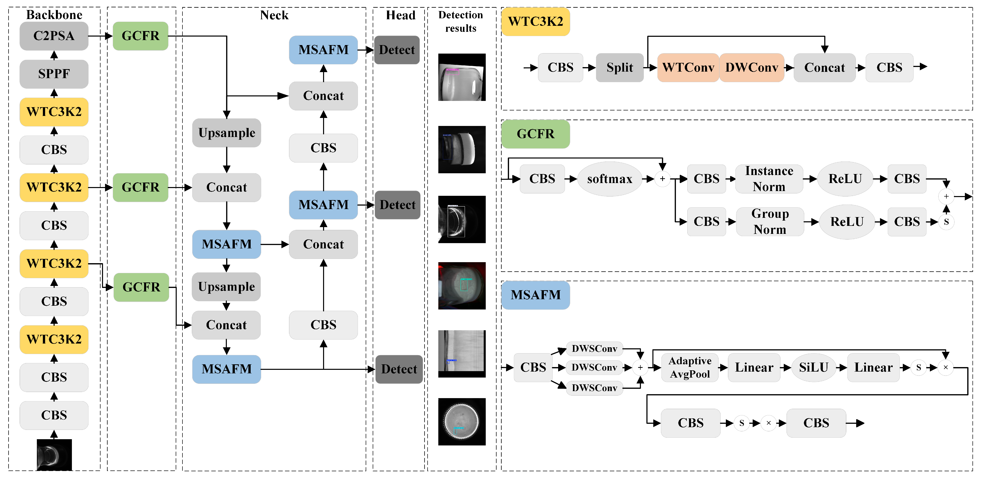
The overall architecture of the proposed SAF-YOLO network for Lyophilized Vial defect detection is illustrated in Figure 1. Its structure remains consistent with YOLOv11, comprising a backbone network for feature extraction, a neck network for feature fusion, and a head network for output prediction. In YOLOv11, the C3K2 modules in the backbone employ stacked convolutions to extract features. However, due to the curved edges of Lyophilized Vial, imaging distortions occur, and standard convolutions—with their fixed receptive fields and frequency response—struggle to capture high-frequency texture details effectively, which may result in missed detections of small defects. Although the YOLOv11 backbone generates multi-scale feature maps at the P3, P4, and P5 layers, these outputs are largely independent and only integrated in the neck network, leaving limited cross-layer and cross-region semantic interaction. Consequently, for defects with large spatial extent, such as longitudinal scratches on the Lyophilized Vial body, the network lacks sufficient contextual awareness. The neck network of YOLOv11 employs fixed C3K2 modules for multi-scale feature fusion, which can aggregate some contextual information but are constrained by a uniform receptive field and thus have limited responsiveness across varying object scales. Given the substantial variation in defect sizes on Vial—ranging from small speck-like contaminants to elongated scratches—this limitation hinders detection performance. To overcome these shortcomings of YOLOv11 in Lyophilized Vial defect detection, this paper introduces several improved modules:
  • WTC3K2 Module in the Backbone Network: We propose an improved residual module, WTC3K2, which replaces the standard convolutions in the conventional C3K2 block with wavelet transform–based convolutions (WTConv). By leveraging frequency-domain decomposition and reconstruction, this design effectively models both low-frequency structural information and high-frequency details, thereby enhancing the network’s sensitivity to subtle texture defects.
  • GCFR Module between the Backbone and Neck Networks: A Global Context Feature Refine (GCFR) module is introduced between the backbone and neck. By generating spatial attention masks and guiding a dual-path fusion process (addition and multiplication), this lightweight design achieves long-range semantic modeling and strengthens contextual awareness.
  • MSAFM Module in the Neck Network: In the neck, we construct a Multi-Scale Attention Fusion Module (MSAFM), which employs a three-branch parallel convolutional structure. By integrating both channel attention and spatial attention, the module enhances multi-scale feature representation and improves recognition performance across targets of varying sizes.

2.2. WTC3K2 Module

The backbone of YOLOv11 employs multiple C3K2 modules for feature extraction. In these modules, conventional convolutions generally use kernels of fixed size. The receptive field during feature extraction is therefore determined by the kernel size: if the kernel is too small, the ability to detect large-scale defects is diminished; conversely, if the kernel is too large, the resolution of small-scale local defects is reduced while the parameter count increases substantially. This fixed-size convolutional kernel setting results in a limited detection field of view and makes it difficult to accommodate the wide variation in defect scales observed in Lyophilized Vial. In contrast, wavelet transform–based WTConv [20] achieves low-/high-frequency decomposition and multi-level reconstruction, thereby providing receptive fields at multiple scales. This enables the extraction of defect features across different sizes while simultaneously enhancing the resolution of texture details and edges, without causing a significant increase in parameters or computational cost. To address the limitations of the original backbone, we propose a novel Wavelet-C3K2 (WTC3K2) module to replace the standard C3K2 module, as illustrated in Figure 2. In this design, WTConv substitutes for traditional convolutions to improve defect detection across scales, and depthwise convolutions are incorporated to further reduce the parameter count.
However, the above explanation alone is insufficient to fully justify the use of wavelet convolutions. To address this, we further clarify how wavelet kernels overcome the limitations of fixed conventional convolutions. Traditional convolutions compute within a fixed spatial receptive field, with weights applied uniformly across all input frequencies, which constrains the model’s ability to represent features of varying scales and textures. When the kernel is small, the model struggles to capture large-scale structural information; when the kernel is large, local details may be overlooked. In contrast, wavelet convolutions enable joint analysis in both spatial and frequency domains. Through multi-resolution decomposition, the input features are divided into subbands of different scales and orientations, each focusing on local variations within specific frequency ranges. This mechanism allows the convolution operation to adaptively adjust its receptive field according to the frequency components of the input features, rather than being limited to a fixed window. Based on this principle, the proposed WTC3K2 module effectively mitigates the rigidity of conventional convolutional structures. First, the low-frequency subband emphasizes the overall vial shape and illumination consistency, enhancing model stability under curved surfaces and varying lighting conditions. Second, the high-frequency subbands highlight defect edges and fine-grained textures, improving the model’s sensitivity to local anomalies such as micro-cracks and scratches. By fusing features across different frequency levels via inverse wavelet transform, WTC3K2 achieves multi-scale, frequency-adaptive feature representation, enriching feature expressiveness and robustness without substantially increasing the number of parameters.
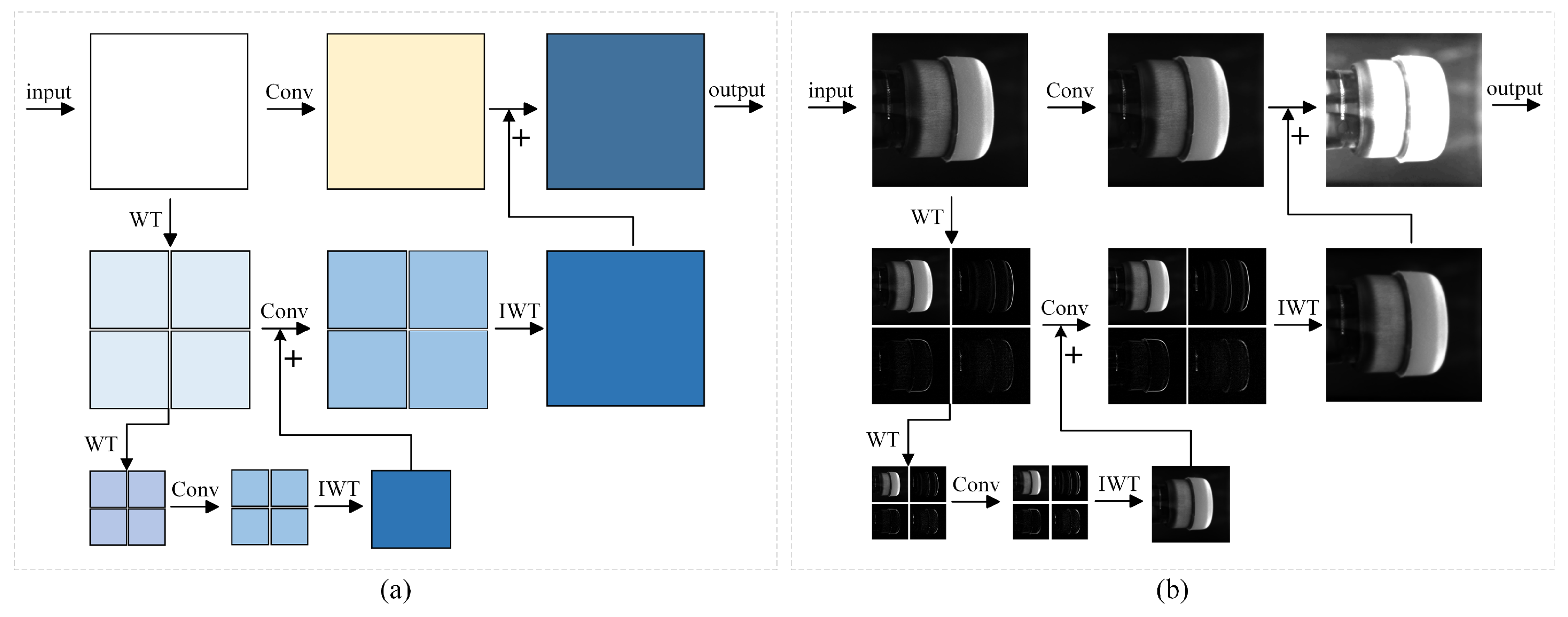
Taking a two-layer convolution as an example, the spatial-domain convolution of WTConv can be decomposed into the following sequence: 2D wavelet transform (WT) → convolution on frequency components (Conv) → 2D inverse wavelet transform (IWT) → residual addition, as illustrated in Figure 3.
First, the input feature map X is subjected to a two-dimensional wavelet transform, yielding four distinct frequency sub-bands Equation (1), the subscripts L and H denote the low- and high-frequency components along the corresponding dimensions, while the superscript (1) indicates the first wavelet convolution operation applied to the input X:
X L L ( 1 ) , X L H ( 1 ) , X H L ( 1 ) , X H H ( 1 ) = W T ( X )
Then, a convolution operation with a 3 × 3 kernel is applied to each frequency sub-band Equation (2):
Y L L ( 1 ) , Y L H ( 1 ) , Y H L ( 1 ) , Y H H ( 1 ) = C o n v 3 × 3 X L L ( 1 ) , X L H ( 1 ) , X H L ( 1 ) , X H H ( 1 )
To further enlarge the receptive field, the low-frequency component obtained along both row and column dimensions X L L ( 1 ) is taken as the input for a second wavelet transform, producing X L L ( 2 ) , X L H ( 2 ) , X H L ( 2 ) , X H H ( 2 ) . An inverse wavelet transform (IWT) is then applied to yield Z ( 2 ) . Leveraging the linearity of IWT, the aggregation can be recursively performed in a bottom-up manner shown in Equation (3):
Z ( 1 ) = I W T Y L L ( 1 ) + Z ( 2 ) , Y L H ( 1 ) , Y H L ( 1 ) , Y H H ( 1 )
The component Z ( 1 ) is treated as a residual term and added to the standard convolution output of the feature map X, yielding the final output of WTConv in Equation (4):
Y = C o n v 3 × 3 ( X ) + Z ( 1 ) = C o n v 3 × 3 ( X ) + I W T Y L L ( 1 ) + Z ( 2 ) , Y L H ( 1 ) , Y H L ( 1 ) , Y H H ( 1 )
The overall workflow of WTC3K2 is summarized in Algorithm 1. It primarily involves standard convolution followed by channel splitting, 2D wavelet processing with WTConv, and depthwise convolution (DWConv), after which residual connections and standard convolution are applied to produce the final output.
Algorithm 1 The Proposed Wavelet-C3K2 (WTC3K2)
Input: Feature map X
Output: Optimized feature map
1:    Apply a 3 × 3 convolution to the input X and perform channel splitting: y = Conv 3 × 3 ( X ) . chunk ( 2 , dim = 1 )
2:     X L L ( 0 ) = y [ 1 ]
3:     Y L L ( 0 ) = Conv 3 × 3 ( W ( 0 ) , X L L ( 0 ) )
4:    for  i = 1 , , l  do
5:         X L L ( i ) , X L H ( i ) , X H L ( i ) , X H H ( i ) = W T ( X L L i )
6:         ( Y L L ( i ) , Y L H ( i ) , Y H L ( i ) , Y H H ( i ) ) = Conv 3 × 3 ( W ( i ) , X L L ( i ) , X H L ( i ) , X H H ( i ) )
7:    end for
8:     Z ( l + 1 ) = 0
9:    for  j = l , , 1  do
10:         Z ( i ) = I W T ( Y L L ( i ) + Z ( i + 1 ) , Y L H ( i ) , Y H L ( i ) , Y H H ( i ) )
11:    end for
12:     Y = Conv 3 × 3 ( X ) + Z ( 1 )
13:    return  Conv 3 × 3 ( y [ 0 ] + DWConv 3 × 3 ( Y ) )

2.3. GCFR Module

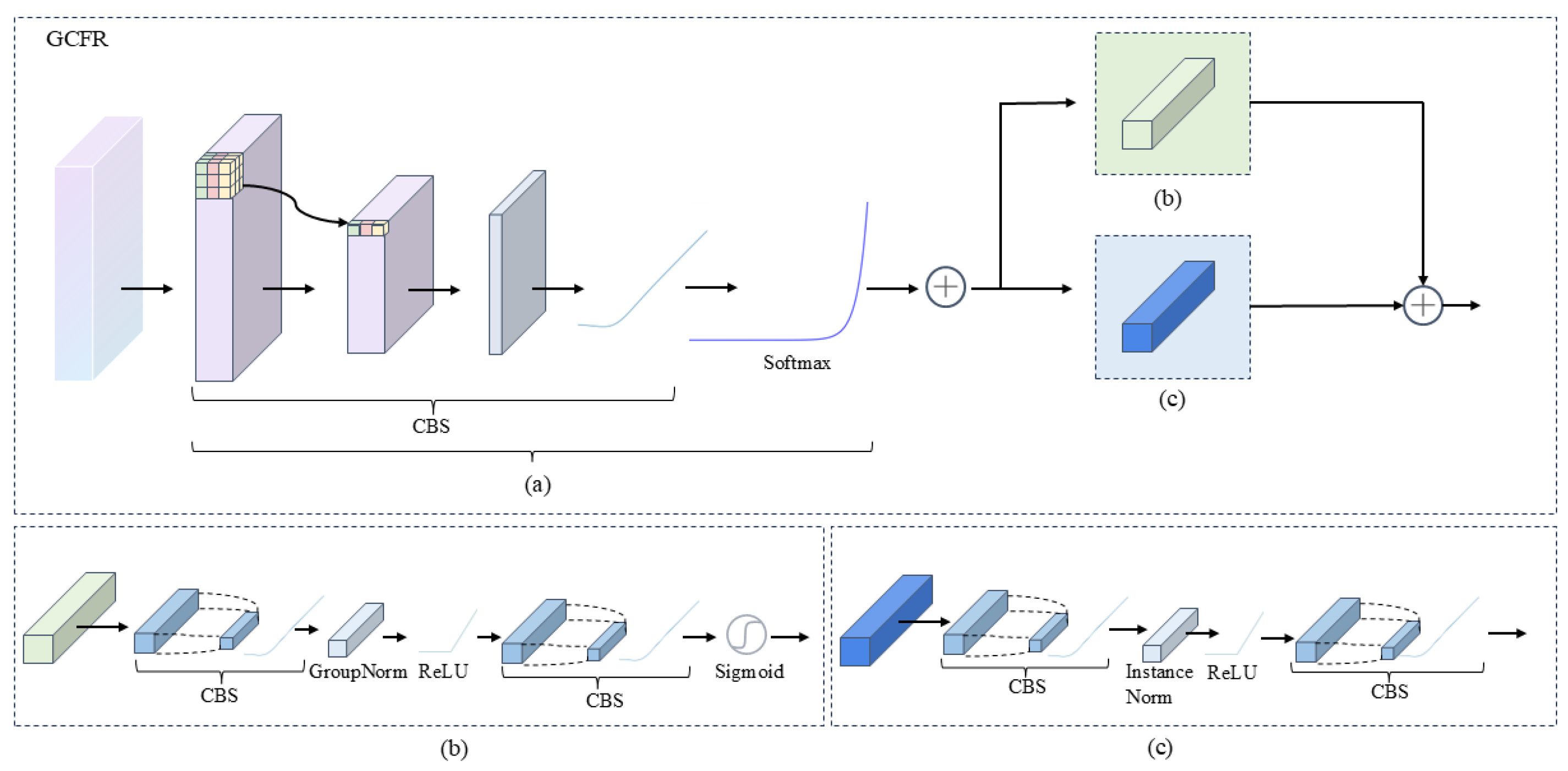
The neck network enhances detection performance through multi-scale feature fusion and serves as a bridge between the backbone and head networks. However, when applied to Lyophilized Vial defect detection, the existing neck structure has two main limitations. First, insufficient contextual information: the transmitted feature maps are dominated by local features, lacking global contextual information, which makes it difficult to capture long-range dependencies [21]. Second, limited multi-scale feature fusion: prior to entering the neck, the feature maps do not undergo sufficient multi-scale semantic enhancement, resulting in suboptimal performance in complex scenarios. To address these issues, we introduce a novel Global Context Feature Refine (GCFR) module between the backbone and neck networks, as illustrated in Figure 4. This module integrates a spatial adaptive pooling structure with a channel attention mechanism, aiming to enrich contextual information and improve multi-scale feature fusion within the network. The pseudocode workflow of the GCFR module is summarized in Algorithm 2.
Algorithm 2 The Proposed Global Context Feature Refine (GCFR) Module
Input: Feature map X
Output: Optimized feature map
Initialization:
Define channel_add_model: Conv1×1 → InstanceNorm → ReLU → Conv1×1
Define channel_mul_model: Conv1×1 → GroupNorm → ReLU → Conv1×1
Set fixed parameters: α = 0.0019 , β = 0.0081
1:    Compute c o n t e x t _ m a s k = Conv 1 × 1 ( X )
2:    Flatten c o n t e x t _ m a s k [ B , 1 , H × W ] , apply softmax along the spatial dimension
3:    Compute c h a n n e l _ m u l _ t e r m = σ ( c h a n n e l _ m u l _ m o d e l ( c o n t e x t ) )
4:     o u t 1 = X × ( 1 + β × c h a n n e l _ m u l _ t e r m )
5:    Compute c h a n n e l _ a d d _ t e r m = c h a n n e l _ a d d _ m o d e l ( c o n t e x t )
6:     o u t 2 = X + α × c h a n n e l _ a d d _ t e r m
7:    return  o u t 1 + o u t 2
The spatial adaptive pooling structure is designed to address the problem of insufficient contextual information. Inspired by Reference [22], we incorporate this structure into the GCFR module. As shown in Figure 4a, it generates adaptive weight distributions over the feature map, thereby introducing global contextual information along the channel dimension. Specifically, a 1 × 1 convolution is first applied to generate the attention weights of the input feature map X. These weights are then normalized using a softmax function to produce a weight map, which is multiplied with the original feature map to obtain the contextual features c o n t e x t in Equation (5):
c o n t e x t = X · softmax Conv 1 × 1 ( X )
The channel attention mechanism is introduced to address the limitation of insufficient multi-scale feature fusion. To better enhance the contrast between target and background regions in feature maps and to enrich the semantic information of target features, the GCFR module incorporates two mechanisms: additive channel attention (Figure 4b) and multiplicative channel attention (Figure 4c). The multiplicative channel attention generates a channel-wise scaling factor with sigmoid activation through a series of 1 × 1 convolutions and nonlinear normalization. This factor is applied multiplicatively to the original features, amplifying or suppressing important channels. In contrast, the additive channel attention reshapes the contextual information into a low-dimensional spatial representation, which is then processed through a set of convolutions and normalization to recover a bias term matching the number of input channels. This bias is added to the features to compensate or correct channel responses. The multiplicative branch serves to adjust the relative importance of channels (i.e., a gating mechanism), while the additive branch injects a global semantic bias signal, enriching feature representation. The coefficients α and β are learnable fusion weights that allow the network to automatically balance the contributions of the additive and multiplicative modifications.
By integrating the spatial adaptive pooling structure with the two channel attention mechanisms, the GCFR module is constructed. Before the feature maps are passed into the neck network, the GCFR module enhances them with contextual information, thereby improving the representation of multi-scale features. During the multi-scale fusion process, the introduced global contextual information also compensates for the deficiencies of local features, ultimately enhancing defect detection performance.

2.4. MSAFM Module

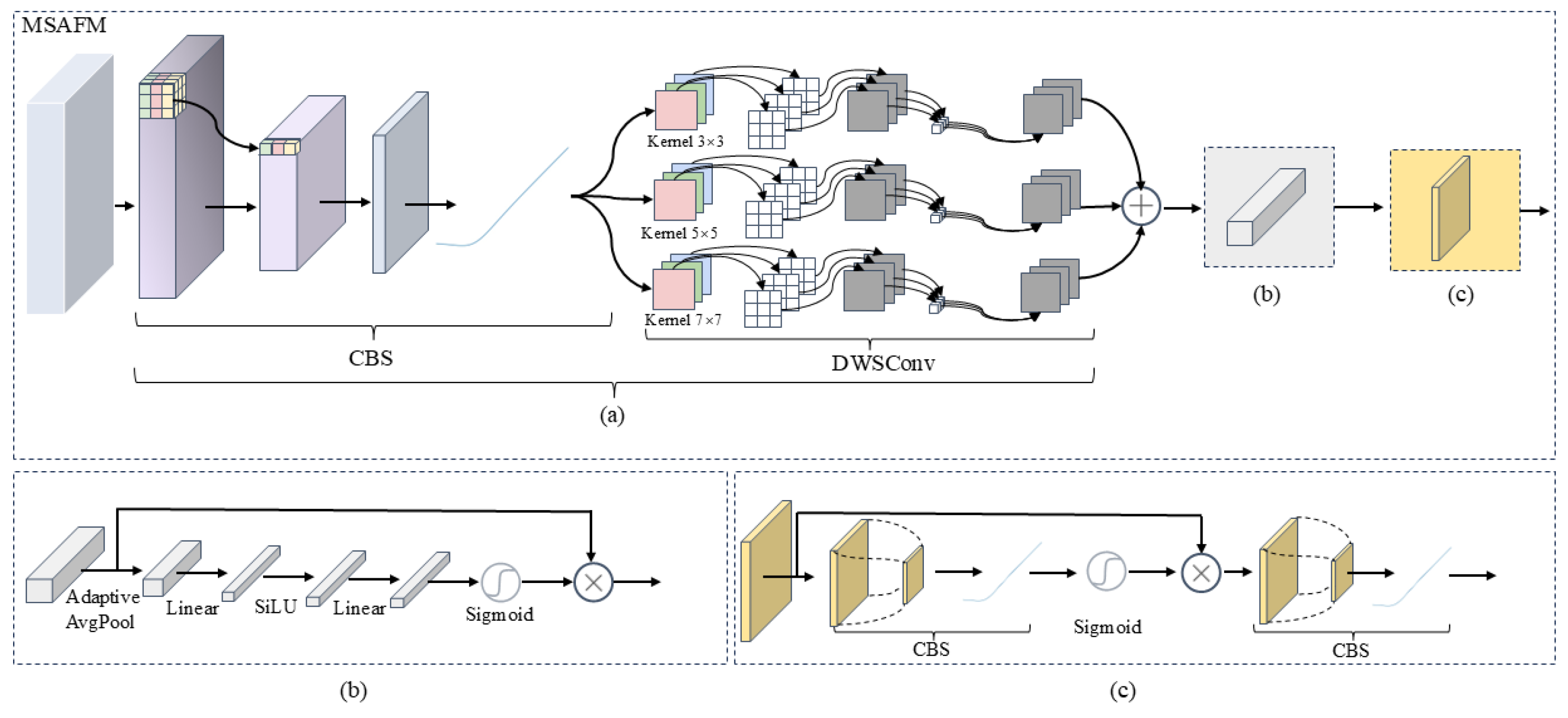
In the neck network of YOLOv11, the C3K2 module remains the primary convolutional block. However, as discussed in Section 3.2, C3K2 relies on fixed-size convolutional kernels, which constrain its receptive field. This limitation reduces performance in Lyophilized Vial defect detection scenarios where backgrounds are complex and defect scales vary significantly. Hence, it is necessary to improve the C3K2 module in the neck network. Unlike the backbone network, which primarily focuses on feature extraction, the neck network emphasizes feature fusion. To this end, we propose the Multi-Scale Attention Fusion Module (MSAFM) as a replacement for the C3K2 module in the neck. As illustrated in Figure 5, MSAFM integrates (a) multi-branch convolutions, (b) the SENet module based on channel attention, and (c) the SAM module based on spatial attention. Together, these components effectively enhance feature representation and fusion capabilities. The pseudocode workflow of the MSAFM structure is presented in Algorithm 3.
Multi-branch convolution module: The input feature map X is first processed by three parallel depthwise separable convolution (DWSConv) branches, with kernel sizes of 3 × 3, 5 × 5, and 7 × 7, respectively. The outputs of these three branches can be expressed as Equation (6):
F k = DWSConv k × k ( X ) , k { 3 , 5 , 7 } .
Subsequently, to ensure the simultaneous presence of small, medium, and large receptive-field features—thereby accommodating the detection requirements of defects at different scales—the feature maps from the three branches are combined through element-wise addition to obtain the fused feature map F = F 3 + F 5 + F 7 :
Algorithm 3 Multi-Scale Attention Fusion Module (MSAFM)
Input: Feature map X
Output: Optimized feature map
Initialization:
Define three depthwise separable convolutions with kernel sizes 3 × 3 , 5 × 5 and 7 × 7
Define channel attention module (SENet)
Define spatial attention module (SAM)
1:     F 1 = DWSConv 3 × 3 ( X )
2:     F 2 = DWSConv 5 × 5 ( X )
3:     F 3 = DWSConv 7 × 7 ( X )
4:     F fused = F 1 + F 2 + F 3
5:     F SENet = SENet ( F fused )
6:     F SAM = SAM ( F SENet )
7:     Shortcut = F SAM + Conv 1 × 1 ( X )
8:    return Shortcut
To further enhance the discriminative capability of the fused features, an attention mechanism is introduced to dynamically adjust feature weights along both the channel and spatial dimensions. First, SENet [23] is employed to perform channel-wise enhancement on the fused features, strengthening key feature channels while suppressing redundant information. The corresponding computation is expressed as Equation (7):
F SENet = F × σ W 2 · SiLU W 1 · GAP ( F )
where W 1 and W 2 denote the weight matrices, G A P represents global average pooling, σ is the sigmoid activation function, and S i L U is the activation function. Subsequently, the SAM module is employed to highlight defect regions and suppress background noise, enabling the network to focus more effectively on spatial locations that are critical for defect detection. The corresponding computation is formulated as Equation (8):
F SAM = F SENet × σ Conv ( F SENet )
By integrating multi-scale convolutional structures with dual attention mechanisms (SENet and SAM), the MSAFM module is capable of simultaneously capturing multi-scale information, strengthening the representation of key features, and focusing on defect regions. As a result, it significantly improves detection accuracy in complex Lyophilized Vial defect detection scenarios.

3. Experiments

3.1. Experimental Environment

The experiments were conducted on a Windows 10 operating system with 32 GB of RAM, an NVIDIA GeForce RTX 2080 Ti GPU (11 GB), and an Intel i5-12400F CPU. The implementation was based on Python 3.10.15 with PyTorch 2.0.0 and CUDA 11.8 for accelerated computation. The detailed experimental parameters are summarized in Table 1.

3.2. Lyophilized Vial Defect Dataset

3.2.1. Collection Environment and Practical Application

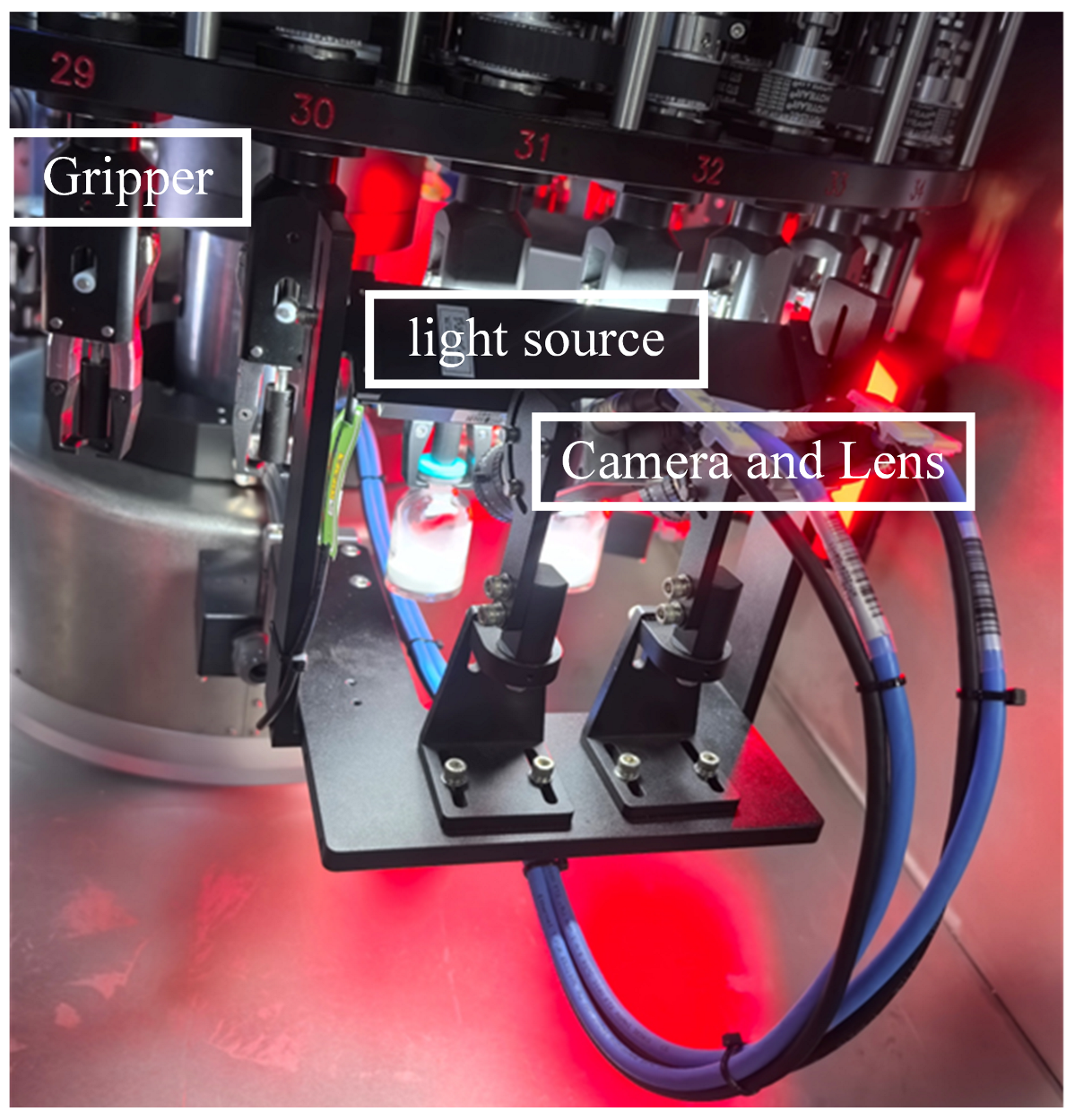
To meet the requirements for high-precision and high-efficiency inspection of Lyophilized Vial appearance during pharmaceutical production, this study developed a machine vision–based intelligent inspection system for online image acquisition of Lyophilized Vial. The system is integrated into the filling and sealing production line, where industrial cameras and vision acquisition modules capture high-speed images of Lyophilized Vials passing through the inspection station. This is achieved without disrupting the existing production rhythm and allows seamless coordination with automated conveying and positioning equipment. Inspection results can be promptly uploaded to the host computer and exchanged with the Manufacturing Execution System (MES). The system primarily targets key defect types, including vial neck cracks, sealing defects, and surface scratches. The six defect categories are annotated with rectangular bounding boxes and independently verified by two professional technicians to ensure labeling consistency. With appropriately configured lighting and industrial cameras, the system can obtain clear and stable images even under high-speed vial movement, ensuring reliable inspection. The inspection system is illustrated in Figure 6, and the parameters of the associated acquisition equipment are listed in Table 2.
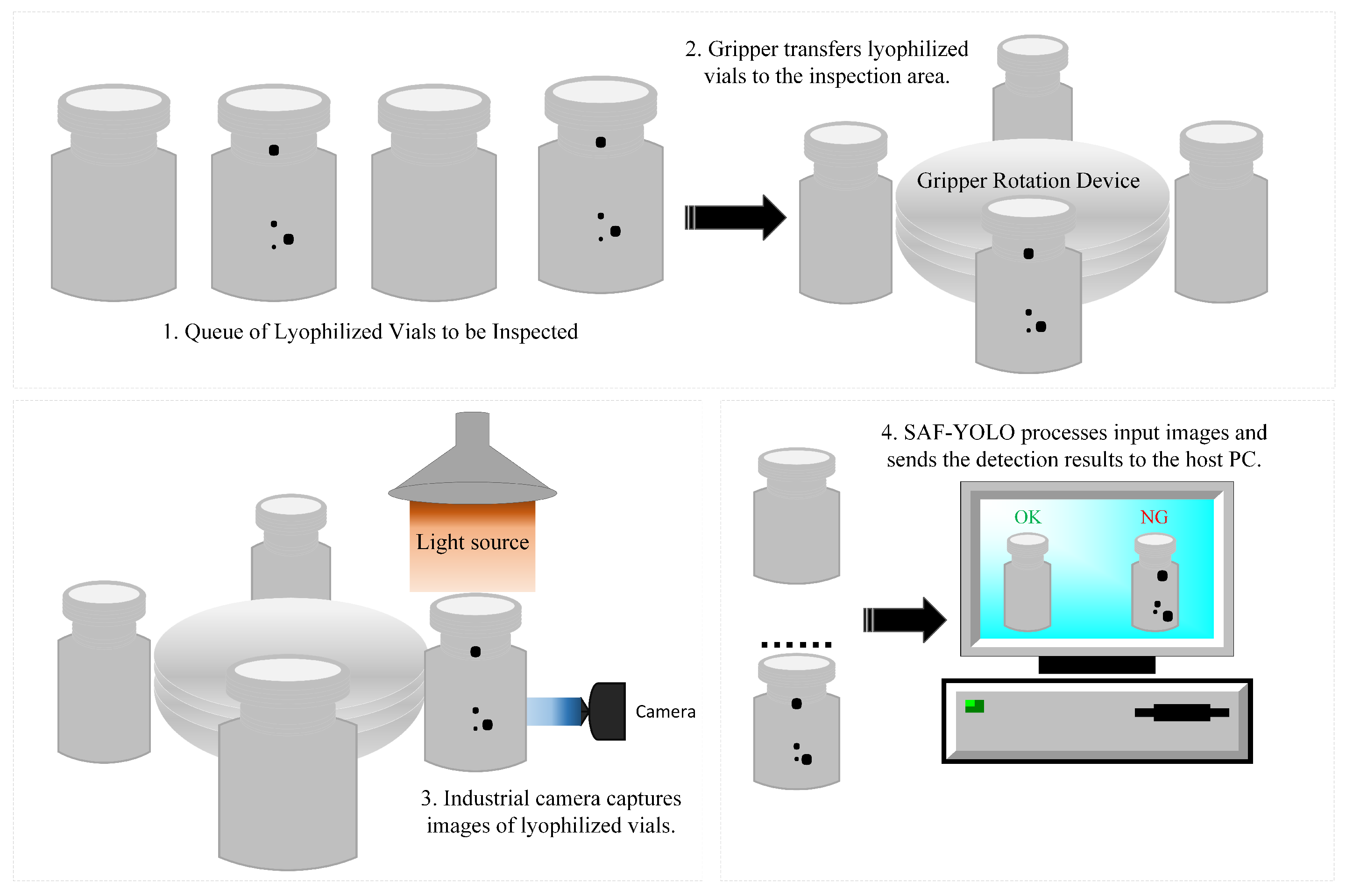
The overall workflow of the Lyophilized Vial visual inspection system is illustrated in Figure 7. Lyophilized Vials to be inspected first enter the gripping station along the conveyor line, where a rotational gripper mechanism ensures continuous and stable automated handling, precisely delivering the Lyophilized Vials to the illumination area. Under the illumination of high-intensity ring lights and auxiliary lighting, the industrial camera synchronizes with the gripper’s rotation to capture high-resolution images of key regions on the Lyophilized Vial. The acquired image data are then uploaded to the host computer platform. SAF-YOLO, deployed on edge devices via TensorRT conversion, performs efficient inference for industrial defect detection, and the results are presented in an intuitive manner.

3.2.2. Lyophilized Vial Defect Dataset Analyse

To evaluate the performance of the model, experiments were conducted on a self-constructed Lyophilized Vial defect dataset. This dataset contains 12,000 images of six types of defects occurring at different locations on Lyophilized Vial, as illustrated in Figure 8. The defect categories include Bottle Expansion (BE), Bottle Bottom (BB), Cap Edge (CE), Cake Surface (CS), Cap Appearance (CA), and Bottle Appearance (BA). Each image has a resolution of 640 × 640 pixels.
Table 3 summarizes the attribute information of each defect category, including the average aspect ratio (Avg (H:W)), average area (Avg (area)), aspect ratio extremal rate (Er (H:W)), and area extremal rate (Er (area)). The results reveal clear morphological differences among the defect categories. The CA category exhibits the largest average aspect ratio (2.9680), indicating the most pronounced vertical elongation, whereas BA has the smallest average aspect ratio (0.7981), reflecting a predominantly horizontal form. CE and CS have average aspect ratios of 1.4505 and 1.2762, respectively, suggesting moderate elongation. In terms of average area, CE defects are the largest (62,361.12), occupying significantly more space in the images compared to other categories. By contrast, BB (average area 2005.32) and BE (average area 3811.16) defects are the smallest, indicating more localized regions that are inherently more difficult to detect. Regarding variation in defect size, the BB category has the highest aspect ratio extremal rate (3.8872), suggesting substantial variability in shape and orientation (e.g., different types of cracks or flaws), which increases the difficulty of detection. Conversely, the BE category has the lowest aspect ratio extremal rate (1.1399), reflecting a more concentrated morphological distribution that facilitates the model’s ability to learn its structural features.

3.3. Evaluation Metrics

For model evaluation, multiple metrics were employed, including precision (P), recall (R), mean average precision (mAP@50), a c c u r a c y , number of parameters (Para), model size (MS), and computational cost (GFLOPs). Precision (P) measures the proportion of predicted positive samples that are true positives, while recall (R) measures the proportion of actual positive samples correctly identified as positive. The mAP@50 represents the mean of the average precision values across all categories at an IoU threshold of 0.5; the closer this value is to 1, the better the detection performance. Accuracy denotes the ratio of correctly predicted samples to the total number of samples. The corresponding calculation formulas are given in Equations (9) and (10):
P = T P T P + F P , R = T P T P + F N , A P = 0 1 P ( R ) d R , m A P = 1 N i = 1 N A P i
a c c u r a c y = T P + T N T P + F N + F P + T N
where N denotes the number of defect categories, and A P i represents the average precision of the i category.

3.4. Experimental Results

3.4.1. Performance Comparison

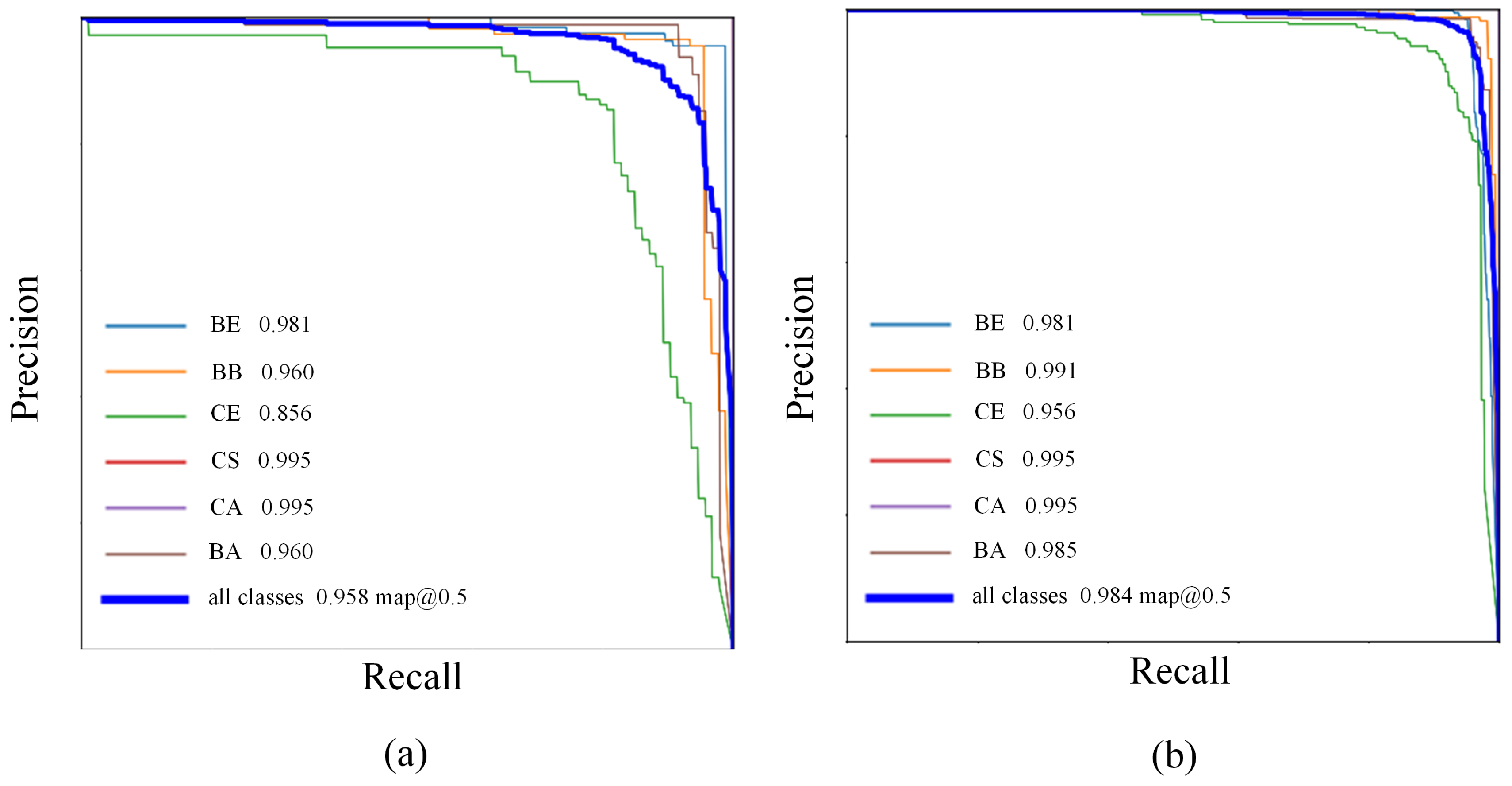
A comparative analysis of detection performance between SAF-YOLO and YOLOv11 [24] on the Lyophilized Vial defect dataset is presented in Table 4. SAF-YOLO achieves improvements across most defect categories, with particularly notable gains in the recall metric. For instance, in detecting the BB category, the AP value increases from 96.0% (YOLOv11) to 99.1%. In the CE category, SAF-YOLO raises recall from 68.0% to 90.9% while simultaneously boosting AP from 85.6% to 95.6%. These results indicate that the proposed frequency-perception module and context-modeling structures significantly enhance detection performance for defect types characterized by low contrast and blurred edges. Overall, SAF-YOLO achieves an mAP@50 of 98.4% on the entire Lyophilized Vial dataset, representing an improvement of 2.6 percentage points over YOLOv11 (95.8%), thereby demonstrating higher accuracy and robustness in Lyophilized Vial defect detection tasks.
Overall, SAF-YOLO demonstrates superior comprehensive detection performance compared to the baseline method. The results confirm that the proposed structural improvements enhance the model’s ability to perceive complex backgrounds and diverse defect types in Lyophilized Vial.
To further compare the detection capabilities of the proposed SAF-YOLO with the baseline YOLOv11, the PR curves of both methods are shown in Figure 9. The PR curve reflects the trade-off between precision and recall. As illustrated in Figure 9b, the area enclosed by the SAF-YOLO PR curve is larger than that of YOLOv11 in Figure 9a, indicating a clear improvement of the proposed method over the baseline. In terms of mAP@50, SAF-YOLO surpasses YOLOv11 by 2.6%. Specifically, the AP values of the BB, CE, and BA categories are improved by 3.1%, 10%, and 2.5%, respectively, with the most significant gain observed in the CE category. These results demonstrate that the proposed algorithm achieves enhanced detection performance across multi-scale defects.
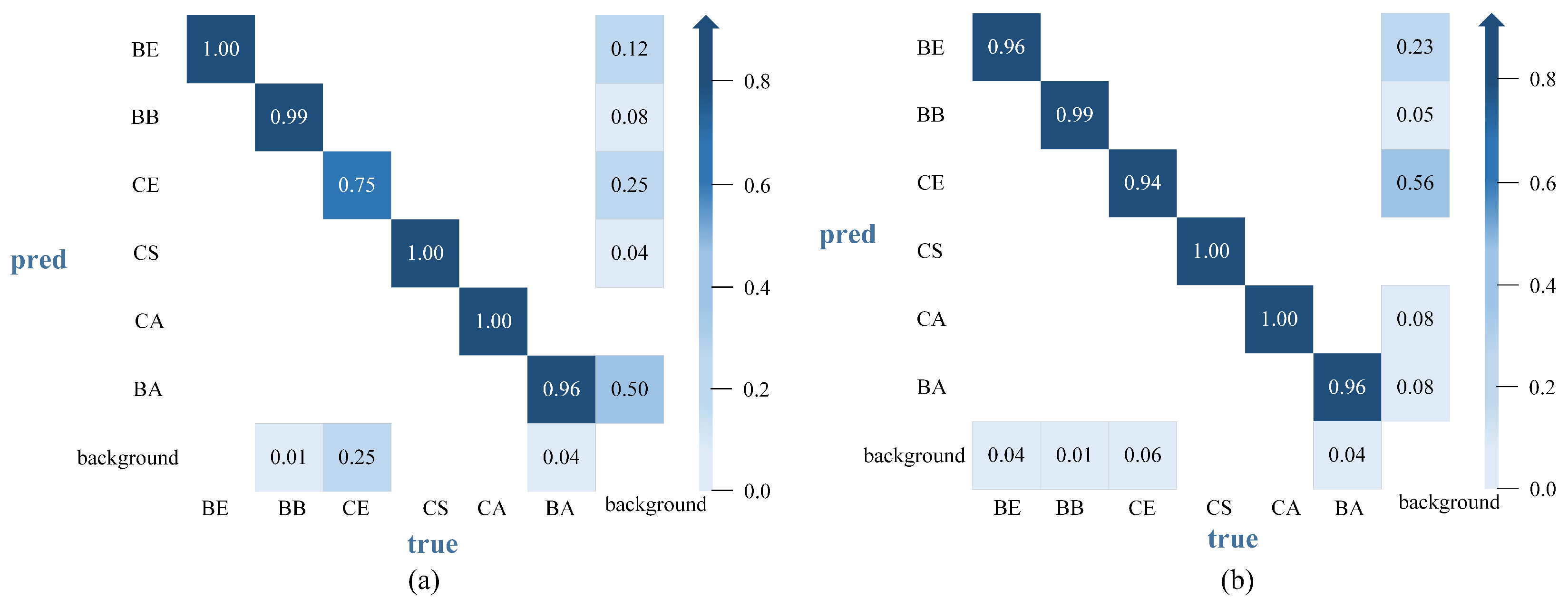
To further analyze the classification accuracy and error distribution of SAF-YOLO and YOLOv11 across different defect categories, confusion matrices were plotted, as shown in Figure 10, with accuracy used as the evaluation metric. From the confusion matrices, it is evident that SAF-YOLO achieves higher recognition accuracy than YOLOv11 across categories. For YOLOv11 (Figure 10a), misclassification is most prominent in the CE category, where accuracy is only 75%, although other categories such as BE, CS, and CA perform relatively well. In contrast, SAF-YOLO (Figure 10b) demonstrates superior performance across all categories, with CE accuracy increasing to 94% and a substantial reduction in background misclassification. Moreover, SAF-YOLO exhibits stronger robustness in handling background noise, with misclassification rates into the background significantly reduced—particularly in the BA and BB categories, where the rates drop to 8% and 5%, respectively.
In summary, the proposed improved algorithm significantly enhances the overall accuracy and robustness of Lyophilized Vial defect recognition, while preserving the lightweight characteristics of the original YOLOv11 architecture.
To comprehensively evaluate the performance of the proposed method, SAF-YOLO was compared with classical object detection algorithms (e.g., Faster R-CNN [25] and SSD [26]) as well as several representative defect detection algorithms in recent years [13,14,15,16]. The experimental results in Table 5 show that SAF-YOLO achieves the best overall performance, with an mAP@50 of 98.4%, precision of 97.4%, and recall of 96.6%. Despite its improved accuracy, SAF-YOLO maintains a compact architecture (4.4 M parameters, 9.3 GFLOPs) and a high inference speed of 89.7 FPS, slightly below YOLOv11 but far more efficient than heavier models such as Faster R-CNN.
These characteristics make SAF-YOLO particularly suitable for industrial deployment, where real-time processing, limited computational resources, and robustness to variable imaging conditions are essential for high-throughput Lyophilized Vial inspection.
In summary, SAF-YOLO delivers superior accuracy, efficiency, and stability in complex Lyophilized Vial detection scenarios, underscoring its practical value for real-world industrial inspection systems.
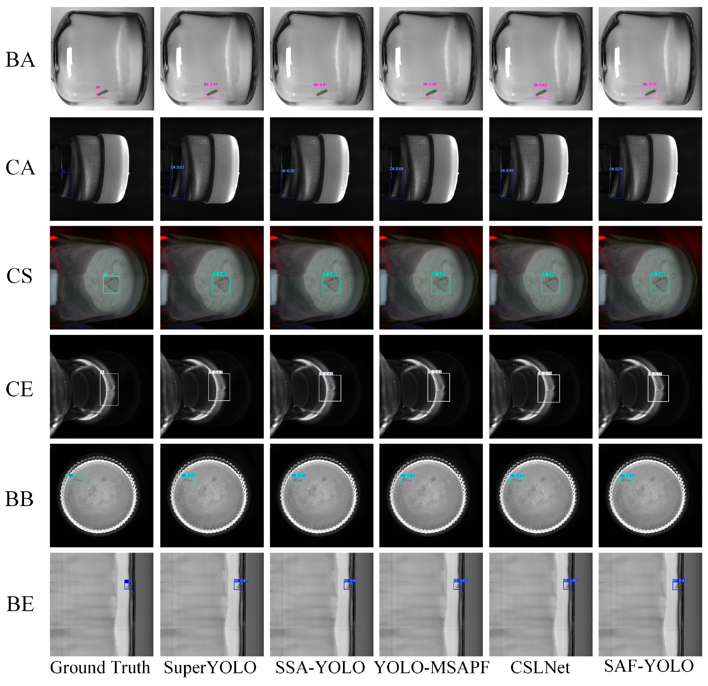
To provide an intuitive comparison of detection performance across different methods, representative images were randomly selected from each defect category for testing. As shown in Figure 11, the detection results demonstrate that the proposed algorithm achieves higher accuracy and confidence scores for most defect types, with overall performance surpassing that of other compared methods.

3.4.2. Ablation Experiments

Using YOLOv11 as the baseline model, systematic ablation experiments were conducted to evaluate the effectiveness of the three proposed modules—WTC3K2, GCFR, and MSAFM—in Lyophilized Vial defect detection. The experiments tested the performance of adding each module individually, adding them in pairs, and incorporating all three simultaneously. The results are presented in Table 6.
In the single-module experiments, all three proposed improvements significantly enhanced detection performance. The WTC3K2 module increased mAP@50 from 95.8% to 97.1% (+1.3%), with only a 0.5M increase in parameters. This result demonstrates that the frequency-aware feature perception introduced by the wavelet transform effectively improves the network’s ability to recognize minute surface defects, such as fine scratches. By jointly modeling low-frequency structural information and high-frequency detail features, WTC3K2 enables the model to extract more discriminative features in regions with low texture contrast. The GCFR module raised mAP@50 to 97.0% (+1.2%), confirming the importance of global semantic modeling. This module is particularly effective in detecting large-scale or structural defects, such as neck deformation and aluminum cap damage. By generating spatial attention masks and incorporating a dual-path fusion mechanism, GCFR enhances the modeling of long-range semantic dependencies. The MSAFM module improved mAP@50 to 96.9% (+1.1%), achieving a favorable balance between performance and model complexity. By integrating channel and spatial attention mechanisms within a multi-scale fusion structure, MSAFM substantially enhances the consistency and accuracy of feature representation for defects of varying sizes and morphologies, such as localized cracks and irregular stains.
In the multi-module combination experiments, the performance gains were even more pronounced. Introducing both WTC3K2 and GCFR increased mAP@50 to 97.9% (+2.1%), highlighting the complementary relationship between frequency-domain texture modeling and global semantic features. Combining WTC3K2 with MSAFM raised mAP@50 to 97.8% (+2.0%), demonstrating the synergistic enhancement between frequency-domain feature extraction and multi-scale fusion. When GCFR and MSAFM were used together, mAP@50 reached 98.1% (+2.3%), indicating that global context modeling and scale-attention mechanisms provide strong complementarity when handling multiple defect types simultaneously.
Finally, integrating all three modules yielded optimal performance: precision (P) 97.4%, recall (R) 96.6%, and mAP@50 98.4%, representing improvements of 4.8%, 3.6%, and 2.6% over the baseline model, respectively. The total parameter count remained at 4.4 M, maintaining a lightweight structure and confirming the effectiveness and synergy of the proposed modules.
The ablation results in Table 6 demonstrate that each proposed module yields distinct and theoretically consistent performance gains. WTC3K2 improves the detection of fine-grained defects due to its ability to separate high-frequency structural components from background noise, thus enhancing the saliency of scratches and particles discarded by standard spatial convolution. GCFR strengthens the detection of shape-varying defects by introducing long-range contextual reasoning that compensates for YOLOv11’s inherently local receptive field. MSAFM contributes to large- and small-defect robustness through adaptive cross-scale attention assignment, mitigating the scale imbalance that limits feature pyramid–based detectors. These improvements are therefore not only empirical but directly aligned with the design motivations of each module.
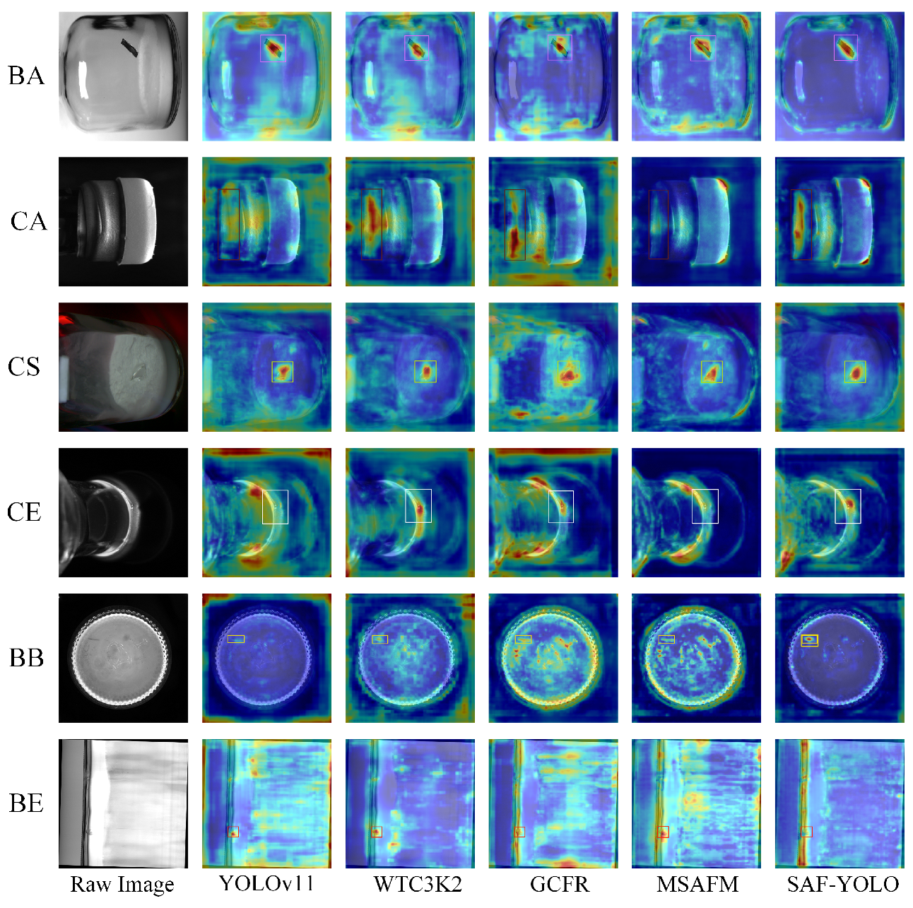
To further verify the effectiveness of the proposed algorithm in the Lyophilized Vial defect detection task, this study employs the Grad-CAM method [27] to visualize the attention regions of YOLOv11 and its improved versions across six categories of Lyophilized Vial defect samples. As shown in Figure 12, YOLOv11 exhibits dispersed attention and insufficient responses to critical regions in several categories. In contrast, after introducing the proposed modules, the model’s ability to focus on defect areas is significantly enhanced, with the heatmaps becoming progressively concentrated on the true defect regions. For instance, in the BE category, the GCFR module effectively strengthens the model’s response to spot-like defects on the bottle surface; in the CE category, the WTC3K2 module markedly improves the perception of edge details along the bottle contour; and in the CS category, the MSAFM module enhances the model’s attention intensity toward the central region of the target. Ultimately, the improved model incorporating all modules demonstrates a more precise and concentrated attention distribution across all categories, thereby validating the effectiveness of each module in enhancing spatial feature extraction, attention guidance, and contextual modeling.
As shown in Table 7, this table presents the quantitative results of different models in evaluating the objective consistency of Grad-CAM heatmaps. To assess the impact of each module on the distribution of feature attention, two metrics were employed: IoU (Intersection over Union) and Coverage. IoU measures the spatial overlap between the model’s attention heatmap and the ground-truth defect regions, reflecting the consistency between the model’s focused areas and the actual defects, with the calculation formula given in Equation (11). Coverage evaluates how completely the heatmap covers the ground-truth defect regions, indicating the adequacy of activation within the defect areas, with the calculation formula provided in Equation (12).
I o U = H b i n G H b i n G
C o v e r a g e = H b i n G G
Here, H b i n denotes the binarized heatmap, and G represents the ground truth.
In the Table 7, SAF-YOLO, which integrates the WTC3K2, GCFR, and MSAFM modules, achieves the best results on both metrics, with a mean IoU of 0.102 and a mean Coverage of 0.396, significantly outperforming the original YOLOv11 model (IoU 0.087, Coverage 0.291). This indicates that the proposed multi-scale feature fusion and global context modeling mechanisms effectively guide the network to spatially focus on the actual defect regions, thereby enhancing the correspondence between feature activations and defect locations.
Moreover, the single-module results reveal that the WTC3K2 module slightly improves the Coverage metric by enhancing local texture features, the GCFR module shows some improvement in IoU, reflecting its positive effect on global information fusion across feature channels, and the MSAFM module further strengthens the response to multi-scale defect features. Overall, the combined use of all three modules demonstrates the highest consistency in feature visualization, validating the rationality and effectiveness of the design proposed in this study.

4. Discussion

This section traces the experimental results back to the model design to explain the reasons for performance improvements of each module across different defect types. First, the WTC3K2 module divides the input features into multiple frequency bands through wavelet decomposition, allowing the network to independently enhance responses to fine defects such as scratches and small particles in the high-frequency subbands. Experimental results demonstrate that this module significantly improves the recall rate for various defects, validating the effectiveness of wavelet-based frequency feature extraction in enhancing defect signal-to-noise ratios. Second, the GCFR module incorporates spatially adaptive pooling along with channel-wise additive and multiplicative fusion mechanisms, enabling the capture of global semantic information across regions. This improves detection performance for morphologically diverse defects and effectively enhances spatial consistency and robustness through the integration of global context. Finally, the MSAFM module employs multi-scale attention fusion to adaptively assign saliency weights across features of different scales, thereby suppressing background interference and strengthening the model’s unified response to defects of varying sizes, reducing the miss rate. In summary, these three modules are designed to address high-frequency microstructure modeling, long-range context perception, and scale-invariant feature representation, respectively, complementing the limitations of traditional spatial convolutions in feature representation from multiple perspectives.
From the perspective of pharmaceutical quality inspection, key performance indicators for detection models include Precision, Recall, and mAP@50. Under the dataset and testing conditions of this study, SAF-YOLO achieved a 3.6% increase in Recall for crack-type defects, indicating that the model can effectively reduce the misclassification of Lyophilized Vial with scratches or potential contamination risks as acceptable products, thereby significantly lowering the miss rate of defective Lyophilized Vial. This improvement is crucial for ensuring the sterility and packaging integrity of pharmaceutical production. Furthermore, considering the real-time detection requirements of industrial production lines, Section 3.4.1 (Table 5) provides a quantitative analysis of the model’s parameters, GFLOPs, and inference latency. The results show that SAF-YOLO substantially improves detection sensitivity while maintaining a low computational load and stable real-time frame rates. Its lightweight design enables deployment on high-speed production lines without compromising throughput. In summary, SAF-YOLO not only achieves improvements in detection accuracy but also demonstrates efficiency and deployability, highlighting its industrial applicability and offering a feasible and effective solution for automated quality control in Lyophilized Vial production lines.
Future research could focus on the following directions:
  • Employing lightweight architectures and model compression strategies to improve real-time performance and deployment efficiency in industrial settings.
  • Utilizing self-supervised or few-shot learning techniques to address challenges associated with high data acquisition costs and limited annotation availability.
  • During the model training phase, a federated learning or distributed training framework can be adopted, allowing each production line or inspection station to retain local data while only sharing model updates (such as gradients or weights) instead of raw images. This approach enables localized data processing and protects sensitive inspection data [28].

Author Contributions

Conceptualization, D.J. and K.Z.; methodology, D.J. and K.Z.; validation, D.J., K.Z. and N.T.; formal analysis, D.J.; resources, D.J.; data curation, K.Z.; writing—original draft preparation, K.Z.; writing—review and editing, D.J. and K.Z.; visualization, N.T. and X.R. All authors have read and agreed to the published version of the manuscript.

Funding

This research received no external funding.

Data Availability Statement

Access to the dataset by contacting the corresponding author.

Conflicts of Interest

The authors declare no conflicts of interest.

References

  1. Chen, X.; Sun, H.; Huang, W.; Jin, J.; Su, M.; Yang, H. The Development of a Novel Headspace O2 Concentration Measurement Sensor for Vials. Sensors 2023, 23, 2438. [Google Scholar] [CrossRef]
  2. Chu, Y.; Yu, X.; Rong, X. A Lightweight Strip Steel Surface Defect Detection Network Based on Improved YOLOv8. Sensors 2024, 24, 6495. [Google Scholar] [CrossRef]
  3. Gong, W.; Zhang, K.; Wu, J.; Yang, C.; Yi, M. Adaptive Visual Inspection Method for Transparent Label Defect Detection of Curved Glass Bottle. In Proceedings of the 2020 International Conference on Computer Vision, Image and Deep Learning (CVIDL), Chongqing, China, 10–12 July 2020; IEEE: New York, NY, USA, 2020. [Google Scholar] [CrossRef]
  4. De Vitis, G.A.; Di Tecco, A.; Foglia, P.; Prete, C.A. Fast Blob and Air Line Defects Detection for High Speed Glass Tube Production Lines. J. Imaging 2021, 7, 223. [Google Scholar] [CrossRef] [PubMed]
  5. Redmon, J.; Divvala, S.; Girshick, R.; Farhadi, A. You Only Look Once: Unified, Real-Time Object Detection. arXiv 2016, arXiv:1506.02640. [Google Scholar] [CrossRef]
  6. Redmon, J.; Farhadi, A. YOLOv3: An Incremental Improvement. arXiv 2018, arXiv:1804.02767. [Google Scholar] [CrossRef]
  7. Khanam, R.; Hussain, M. What is YOLOv5: A Deep Look into the Internal Features of the Popular Object Detector. arXiv 2024, arXiv:2407.20892. [Google Scholar] [CrossRef]
  8. Wang, C.-Y.; Bochkovskiy, A.; Liao, H.-Y.M. YOLOv7: Trainable Bag-of-Freebies Sets New State-of-the-Art for Real-Time Object Detectors. arXiv 2022, arXiv:2207.02696. [Google Scholar] [CrossRef]
  9. Yaseen, M. What is YOLOv8: An In-Depth Exploration of the Internal Features of the Next-Generation Object Detector. arXiv 2024, arXiv:2408.15857. [Google Scholar] [CrossRef]
  10. Li, Z.; Xiong, F.; Huang, B.; Li, M.; Xiao, X.; Ji, Y.; Xie, J.; Liang, A.; Xu, H. MGD-YOLO: An Enhanced Road Defect Detection Algorithm Based on Multi-Scale Attention Feature Fusion. Comput. Mater. Contin. 2025, 84, 5613–5635. [Google Scholar] [CrossRef]
  11. Zhao, M.; Li, X.; Li, M.; Mu, B. FSS-YOLO: The Lightweight Drill Pipe Detection Method Based on YOLOv8n-obb. Comput. Mater. Contin. 2025, 84, 2827–2846. [Google Scholar] [CrossRef]
  12. Luo, S.; Zheng, S.; Zhao, Y. YOLO-DEI: Enhanced Information Fusion Model for Defect Detection in LCD. Comput. Mater. Contin. 2024, 81, 3881–3901. [Google Scholar] [CrossRef]
  13. Zhang, J.; Lei, J.; Xie, W.; Fang, Z.; Li, Y.; Du, Q. SuperYOLO: Super Resolution Assisted Object Detection in Multimodal Remote Sensing Imagery. IEEE Trans. Geosci. Remote Sens. 2023, 61, 5605415. [Google Scholar] [CrossRef]
  14. Huang, X.; Zhu, J.; Huo, Y. SSA-YOLO: An Improved YOLO for Hot-Rolled Strip Steel Surface Defect Detection. IEEE Trans. Instrum. Meas. 2024, 73, 5040017. [Google Scholar] [CrossRef]
  15. Wang, G.-Q.; Zhang, C.-Z.; Chen, M.-S.; Lin, Y.-C.; Tan, X.-H.; Liang, P.; Kang, Y.-X.; Zeng, W.-D.; Wang, Q. Yolo-MSAPF: Multiscale Alignment Fusion with Parallel Feature Filtering Model for High Accuracy Weld Defect Detection. IEEE Trans. Instrum. Meas. 2023, 72, 5022914. [Google Scholar] [CrossRef]
  16. Xu, H.; Liu, Q.; Zhu, J.; Dai, H.; Zhang, D. CSLNet: An Enhanced YOLOv8-Based Approach to Defect Surface Foreign Objects in Lyophilized Powder. Signal Image Video Process. 2025, 19, 728. [Google Scholar] [CrossRef]
  17. Vijayakumar, A.; Vairavasundaram, S.; Koilraj, J.A.S.; Rajappa, M.; Kotecha, K.; Kulkarni, A. Real-Time Visual Intelligence for Defect Detection in Pharmaceutical Packaging. Sci. Rep. 2024, 14, 18811. [Google Scholar] [CrossRef] [PubMed]
  18. Chen, D.; Zhang, J.; Jiao, Z.; Lei, H.; Ma, J.; Wu, L.; Zhong, Z. Multi-Scale Surface Defect Detection Method for Bottled Products Based on Variable Receptive Fields and Gather–Distribute Feature Fusion Mechanism. Comput. Electr. Eng. 2024, 116, 109148. [Google Scholar] [CrossRef]
  19. Pei, J.; Li, S.; Li, Y. A Real-Time Surface Defects Detection Model via Dual-Branch Feature Extraction and Dynamic Multi-Scale Fusion Attention. Digit. Signal Process. 2024, 152, 104582. [Google Scholar] [CrossRef]
  20. Finder, S.E.; Amoyal, R.; Treister, E.; Freifeld, O. Wavelet Convolutions for Large Receptive Fields. arXiv 2024, arXiv:2407.05848. [Google Scholar] [CrossRef]
  21. Choi, J. Global Context Attention for Robust Visual Tracking. Sensors 2023, 23, 2695. [Google Scholar] [CrossRef]
  22. Cao, Y.; Xu, J.; Lin, S.; Wei, F.; Hu, H. GCNet: Non-Local Networks Meet Squeeze-Excitation Networks and Beyond. arXiv 2019, arXiv:1904.11492. [Google Scholar] [CrossRef]
  23. Hu, J.; Shen, L.; Albanie, S.; Sun, G.; Wu, E. Squeeze-and-Excitation Networks. arXiv 2019, arXiv:1709.01507. [Google Scholar] [CrossRef]
  24. Khanam, R.; Hussain, M. YOLOv11: An Overview of the Key Architectural Enhancements. arXiv 2024, arXiv:2410.17725. [Google Scholar] [CrossRef]
  25. Ren, S.; He, K.; Girshick, R.; Sun, J. Faster R-CNN: Towards Real-Time Object Detection with Region Proposal Networks. IEEE Trans. Pattern Anal. Mach. Intell. 2017, 39, 1137–1149. [Google Scholar] [CrossRef]
  26. Liu, W.; Anguelov, D.; Erhan, D.; Szegedy, C.; Reed, S.; Fu, C.-Y.; Berg, A.C. SSD: Single Shot MultiBox Detector. In Proceedings of the Computer Vision—ECCV 2016, Amsterdam, The Netherlands, 11–14 October 2016; Leibe, B., Matas, J., Sebe, N., Welling, M., Eds.; Springer: Cham, Switzerland, 2016; pp. 21–37. [Google Scholar] [CrossRef]
  27. Selvaraju, R.R.; Cogswell, M.; Das, A.; Vedantam, R.; Parikh, D.; Batra, D. Grad-CAM: Visual Explanations from Deep Networks via Gradient-Based Localization. Int. J. Comput. Vis. 2019, 128, 336–359. [Google Scholar] [CrossRef]
  28. Yang, B.; Lei, Y.; Li, N.; Li, X.; Si, X.; Chen, C. Balance Recovery and Collaborative Adaptation Approach for Federated Fault Diagnosis of Inconsistent Machine Groups. Knowl.-Based Syst. 2025, 317, 113480. [Google Scholar] [CrossRef]
Figure 1. Illustration of the overall SAF-YOLO architecture. The yellow, green, and blue regions correspond to the proposed WTC3K2, GCFR, and MSAFM modules, respectively.
Electronics 14 04526 g001
Figure 2. Architecture of the proposed WTC3K2 module.
Electronics 14 04526 g002
Figure 3. Illustration of the two-layer wavelet decomposition workflow in WTConv: (a) simplified schematic diagram of WTConv; (b) actual data visualization of WTConv.
Electronics 14 04526 g003
Figure 4. Architecture of the GCFR module: (a) spatial adaptive pooling structure; (b) additive channel attention; (c) multiplicative channel attention.
Electronics 14 04526 g004
Figure 5. Architecture of the proposed MSAFM module: (a) multi-branch convolution module; (b) SENet; (c) SAM.
Electronics 14 04526 g005
Figure 6. Visual Inspection System for Lyophilized Vials.
Electronics 14 04526 g006
Figure 7. Workflow of the Lyophilized Vial Visual Inspection System.
Electronics 14 04526 g007
Figure 8. Representative Lyophilized Vial defects at typical structural locations.
Electronics 14 04526 g008
Figure 9. Precision–recall (PR) curves: (a) YOLOv11; (b) proposed SAF-YOLO.
Electronics 14 04526 g009
Figure 10. Confusion matrices for defect detection: (a) YOLOv11 baseline; (b) proposed SAF-YOLO.
Electronics 14 04526 g010
Figure 11. Detection results of SAF-YOLO and representative algorithms on Lyophilized Vial defects.
Electronics 14 04526 g011
Figure 12. Grad-CAM Visualization Results of Each Module in SAF-YOLO on the Lyophilized Vial Defect Dataset.
Electronics 14 04526 g012
Table 1. Experimental parameter settings.
ParameterValue
Batch size24
Epochs300
OptimizerSGD
Learning rate0.01
Threads4
Image size640 × 640
Training set80%
Test set10%
Validation set10%
data augmentationMosaic, Mixup, random perspective
Table 2. Equipment and Environmental Setup for Lyophilized Vial Dataset Acquisition.
CategorySpecificationManufacturerDescription
Industrial CameraBasler ALA1920-40GMBasler AG (Ahrensburg, Germany)1/1.2 inch CMOS sensor, resolution
1920 × 1200, frame rate 40 fps, GigE interface, pylon = 8.1.0.
LensComputar M1628-MPXComputar (Tokyo, Japan)Focal length 16 mm, maximum aperture F2.8, compatible with 2/3 inch sensor, high resolution support.
Light SourceLDL2-19X4SW2(A)CCS Inc. (Kyoto, Japan)Emission color: White; correlated color temperature: 7000 K; dimensions: W 28 × D 6.4 × H 13 mm; input voltage: 24 V DC; power consumption: 1.3 W max.
Table 3. Statistical analysis of Lyophilized Vial defect dataset.
ClassAvg (H:W)Avg (Area)Er (H:W)Er (Area)
Bottle Expansion1.02643811.161.13993.4886
Bottle Bottom1.11712005.323.88723.9405
Cap Edge1.450562,361.122.53651.8596
Cake Surface1.276218,128.581.21001.5002
Cap Appearance2.968041,428.791.33421.5551
Bottle Appearance0.798111,376.211.70971.6978
Table 4. Performance comparison of YOLOv11 and SAF-YOLO on the Lyophilized Vial dataset.
ClassYOLOv11 P%YOLOv11 R%YOLOv11 mAP%SAF-YOLO P%SAF-YOLO R%SAF-YOLO mAP%
BE95.098.898.198.494.998.1 (-)
BB95.295.696.097.898.299.1 (↑ 3.1)
CE91.368.085.692.490.995.6 (↑ 10.0)
CS99.010099.599.610099.5 (-)
CA99.410099.598.210099.5 (-)
BA92.293.896.098.295.798.5 (↑ 2.5)
six defect types95.492.795.897.496.698.4 (↑ 2.6)
(-) indicates no change; (↑) indicates improvement.
Table 5. Performance comparison of SAF-YOLO and representative algorithms on the Lyophilized Vial defect dataset.
ModelP (%)R (%)mAP@50 (%)ParamsGFLOPsFPS
Faster R-CNN [25]69.494.486.7136.8M40112.8
SSD [26]56.156.793.924.4M27536
YOLOv11 [24]95.492.795.82.6M6.3105
SuperYOLO [13]92.794.295.61.6M3.152
SSA-YOLO [14]94.692.295.63.3M8.563.3
YOLO-MSAPF [15]93.691.594.63.6M2.354
CSLNet [16]94.892.594.93.3M7.961.4
SAF-YOLO97.496.698.44.4 M9.389.7
Table 6. Performance of SAF-YOLO in ablation experiments on the Lyophilized Vial dataset.
No.WTC3K2GCFRMSAFMP (%)R (%)mAP (%)Para (M)MS (MB)
1---92.693.095.82.65.5
2--96.495.297.13.16.6
3--95.994.897.03.98.2
4--96.195.596.92.75.9
5-96.896.097.94.18.6
6-97.196.697.83.37.0
7-97.195.998.14.08.3
897.496.698.44.49.3
(-) indicates not add this item; ✓ indicates add this item.
Table 7. Quantitative Evaluation of Grad-CAM Visualization Consistency for Different Models.
ModelIoUCoverageConclusion on Visualization Consistency
YOLOv110.0870.304Basic level, general edge localization.
WTC3K20.0910.310The detection performance is slightly improved.
GCFR0.0890.308limited improvement on consistency.
MSAFM0.0930.312Multi-scale feature enhancement improves consistency.
SAF-YOLO0.1020.396Significantly enhances consistency.
Disclaimer/Publisher’s Note: The statements, opinions and data contained in all publications are solely those of the individual author(s) and contributor(s) and not of MDPI and/or the editor(s). MDPI and/or the editor(s) disclaim responsibility for any injury to people or property resulting from any ideas, methods, instructions or products referred to in the content.