1. Introduction
The bearingless interior permanent magnet synchronous motor (BIPMSM) is a novel machine that integrates magnetic suspension technology with an interior permanent magnet synchronous motor. In contrast to conventional interior permanent magnet synchronous motors, it incorporates not only the traditional torque windings but also an additional set of suspension force windings, which are employed to generate suspension forces for rotor suspension control [
1,
2]. The torque and suspension force windings generate the rotational torque and suspension force, respectively, enabling simultaneous rotor rotation and suspension. The BIPMSM possesses the advantages of a high-power factor, long service life, high efficiency, and compact structure [
3,
4]. Moreover, it eliminates the problems associated with mechanical bearings, such as wear, noise, and temperature rise. Therefore, it has broad application prospects in industrial scenarios requiring high speed, high reliability, and high cleanliness, including the equipment manufacturing industry, aerospace, and pharmaceutical industries [
5,
6]. Particularly in the field of computer numerical control machine tools, BIPMSMs fully satisfy the stringent requirements of high reliability, high precision, high rotational speed, and lubrication-free operation. Consequently, BIPMSMs have become one of the hot topics in the research field of bearingless motors.
However, during the manufacturing of the BIPMSM, imperfections in machining accuracy may lead to an uneven mass distribution of the rotor, resulting in rotor unbalance vibration during practical operation [
7,
8]. Since it is difficult to achieve complete coincidence between the geometric axis and the inertia axis of the motor rotor, exciting forces are generated on the motor during operation. The exciting force has the same frequency as the rotational speed and is proportional to the square of the rotational speed [
9]. When the motor reaches a high speed, even minor deviations can induce significant unbalanced vibrations. If such vibrations exceed the air-gap limit, rotor suspension failure may occur. This not only restricts further increases in rotational speed but also severely compromises the stable operation of the BIPMSM [
10]. In addition, vibration signals detected by the displacement sensor during motor operation may induce current saturation in the power amplifier, thereby degrading the stability of the entire control system [
11]. Consequently, investigating suppression strategies for rotor unbalanced vibrations in BIPMSMs is of considerable theoretical and practical significance.
In recent years, various approaches have been proposed to suppress vibrations in bearingless motors [
12,
13]. In [
14], a rotor suspension dynamics model is developed to describe synchronous vibrations caused by rotor mass unbalance, based on which a full compensation strategy combining phase-shifted notch filter optimization, feedforward compensation, and stability analysis is designed to achieve effective vibration suppression. In [
15], a simplified control model for the rotor mass eccentricity system is developed, and an improved multi-band phase compensation repetitive control strategy is proposed to compensate for rotor mass eccentricity, effectively suppressing rotor vibrations. In [
16], a compensation scheme for suspension position eccentricity in magnetic suspension motors is proposed to minimize the amplitude of the eccentric suspension current vector. This scheme dynamically adjusts the rotor’s suspension position in two dimensions, ensuring stable suspension and effectively suppressing rotor eccentricity vibration. In [
17], a coordinate system with the stator geometric center as the origin is established, and a feedforward compensation algorithm based on the unbalance mass radius product is used to compensate for the mass unbalance displacement of the rotor. In [
18], the reason for vibration caused by rotor unbalanced mass is analyzed, and a control strategy combining unbalanced feedforward compensation with current compensation is proposed to realize vibration compensation control. However, these studies mainly concentrate on suppressing unbalanced vibrations caused by rotor mass eccentricity, while overlooking the harmonic vibrations introduced by the dead-time (DT) effect during the control process. In [
19], a novel scheme is proposed for the online estimation of motor flux linkage and voltage-source inverter nonlinearity, aimed at motor condition monitoring. This approach accounts for the estimation and compensation of distortion voltages caused by inverter nonlinearity, enabling direct online observation and compensation of DT voltage in the system. In [
20], the impacts of DT effects on motor current and voltage harmonics are analyzed, and an adaptive controller is employed to mitigate these adverse effects, thereby achieving effective direct torque control. In [
21], a new DT compensation method based on a modified repetitive controller is introduced for motor drives. This method effectively suppresses the sixth-order harmonics and their multiples in the synchronous reference frame without relying on precise current sampling, resulting in reduced total harmonic distortion in the current. The aforementioned studies reveal that DT is an essential part of motor control, as it not only reduces the overall efficiency of the control system but also makes the control effect worse. The DT effect increases the high-order harmonic currents of torque and suspension force windings in the BIPMSM, and causes rotor vibration [
22]. In addition, the increased complexity of the controller design amplifies the impact of system disturbances, thereby reducing the reliability of the motor [
23]. Moreover, the above control schemes generally use a Proportional–Integral (PI) controller to regulate system parameters, but it still presents certain limitations in practice. The PI controller shows a delayed response to external disturbances, making it difficult to suppress transient interferences in a timely manner. Meanwhile, its performance is highly sensitive to gain tuning, and parameter deviations may significantly deteriorate system dynamics or even cause instability [
24].
A control strategy based on a Proportional–Integral–Resonant (PIR) controller is proposed to suppress rotor vibrations in BIPMSMs caused by rotor mass eccentricity and DT effects. Through an in-depth analysis of the operating mechanism and rotor vibration characteristics of the BIPMSM, a control approach combining a modified Proportional–Resonant (PR) controller and a PI controller in a parallel configuration is developed. The combination of PI and the modified PR controllers reduces the high sensitivity of the PI controller to gain settings, enhancing system stability. In a parallel configuration, the modified PR controller’s frequency tracking capability compensates for the PI controller’s limitations, improving robustness and reducing the need for precise parameter tuning. Meanwhile, the steady-state error elimination capability of the PI controller and the harmonic compensation characteristics of the modified PR controller are integrated, allowing precise tracking of the fundamental current component and effective suppression of harmonic components, whereby rotor vibrations induced by mass eccentricity and DT effects are efficiently mitigated.
The rest of this paper is organized as follows. In
Section 2, the BIPMSM’s mathematical model is presented, and the vibration mechanisms are analyzed. In
Section 3, the vibration suppression control strategy for the BIPMSM is designed. In
Section 4, the effectiveness and accuracy of the proposed control method are demonstrated through MATLAB (R2022b) simulations. Finally,
Section 5 concludes this article.
2. Analysis of BIPMSM Principles and Vibration Mechanisms
2.1. Introduction to the Principles of BIPMSM
The radial suspension force of BIPMSM originates from the superposition of the torque magnetic field and the suspension force magnetic field, and the stable suspension of the rotor can be realized by adjusting the current of the suspension force winding [
25]. As shown in
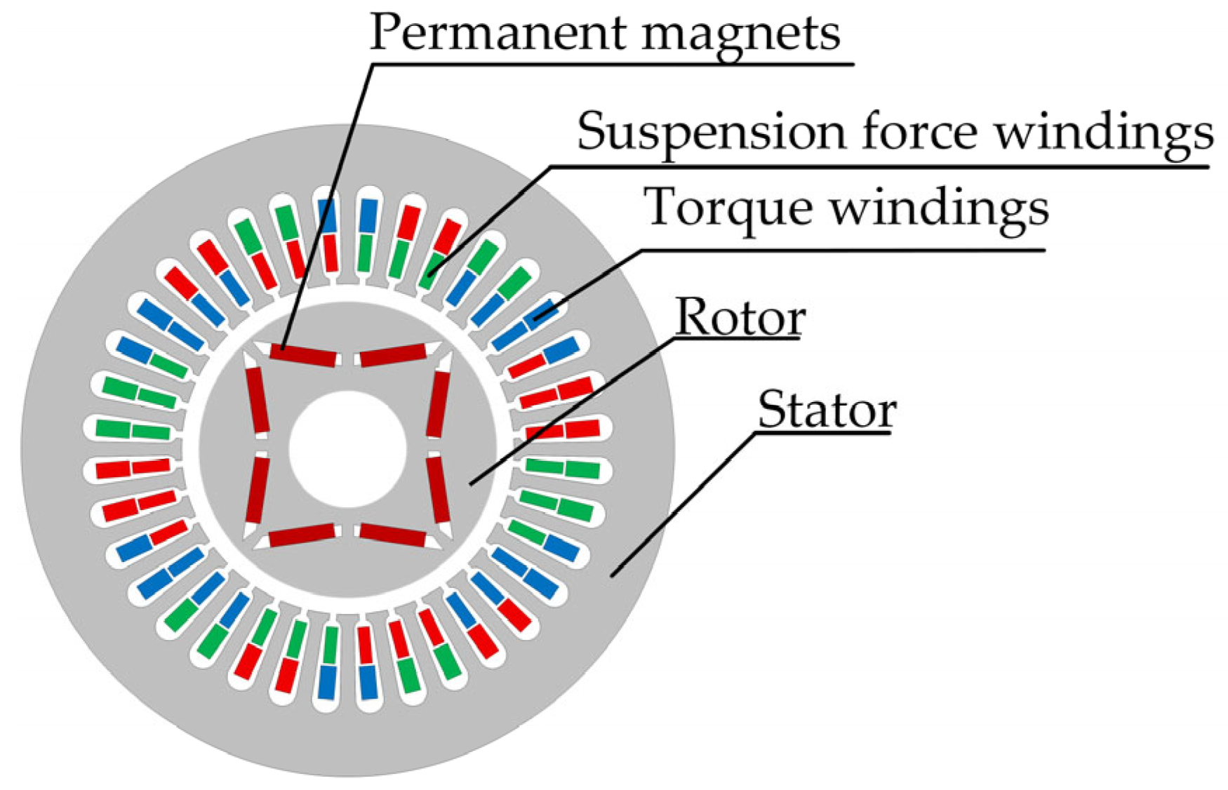
Figure 1, the structure of the BIPMSM primarily consists of torque windings, suspension force windings, permanent magnets, stator, and rotor.
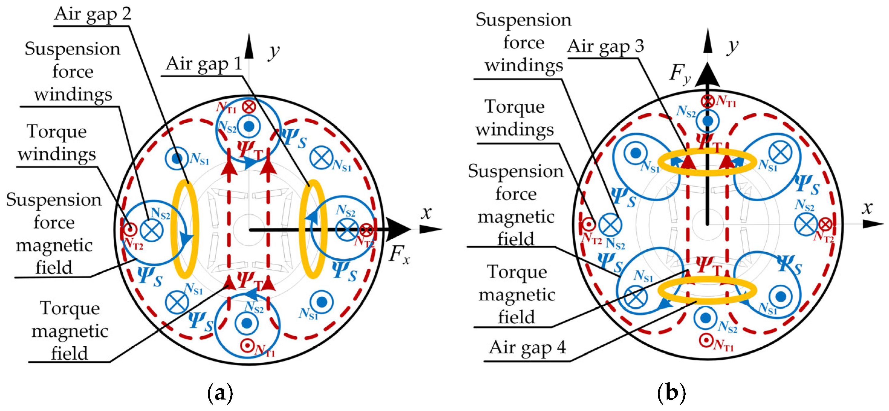
In order to illustrate the radial suspension force generation mechanism of the BIPMSM more intuitively, according to the controlled suspension force generation conditions, the motor configuration assumes
PT = 1 pole pairs for torque windings and
PS = 2 pole pairs for suspension force windings, with synchronized current frequencies and co-rotating magnetic fields. The principle of suspension force generation of the BIPMSM in the x-y stationary coordinate system is shown in
Figure 2. In
Figure 2,
NS1 and
NS2 are the two-phase suspension force windings, while
NT1 and
NT2 are the two-phase torque windings. As illustrated in
Figure 2a, when an appropriate current is applied to the suspension force winding
NS2, the two-pole-pair magnetic field
ΨS generated by the suspension force winding is superimposed with the single-pole-pair torque magnetic field
ΨT. The magnetic field interaction increases the air-gap flux density in region 1, while in region 2, the flux density decreases. This imbalance in air-gap flux density causes the Maxwell force in region 1 to exceed that in region 2, resulting in a radial suspension force
Fx along the positive x-axis, which drives the rotor to suspend. Similarly, applying an appropriately sized current to the suspension force winding
NS1 with the polarity shown in
Figure 2b generates a radially directed suspension force
Fy along the y-axis on the rotor, whose magnitude can be adjusted. Therefore, by controlling the currents in the suspension force windings, the magnitude and direction of the suspension force can be regulated, thereby achieving stable suspension of the motor.
2.2. Mathematical Models of Suspension Force and Torque
An embedded permanent magnet rotor structure is employed in the BIPMSM, with permanent magnets positioned inside the rotor core. Based on the principle of virtual displacement, the components of the radial suspension force of the BIPMSM rotor in the d-q rotational coordinate system can be obtained and expressed as follows:
where
iTd and
iTq are the current components of the torque windings in the d-q rotational coordinate system.
iSd and
iSq are the current components of the suspension force windings in the same system.
if is the equivalent excitation current of the permanent magnets.
Md and
Mq are the mutual inductance coefficients between the torque windings and suspension force windings in the d-q rotational coordinate system.
Through the inverse Park transformation, the suspension force of the BIPMSM can be derived as follows in the α-β stationary coordinate system:
where
ωm is the mechanical angular velocity of the rotor.
iSα and
iSβ are the current components of the torque windings in the α-β stationary coordinate system. The phase angle is
.
In the BIPMSM, in addition to the controllable electromagnetic suspension force, the single-sided magnetic force component acting on the interior permanent magnet rotor when it undergoes eccentric displacement increases with displacement. This phenomenon must be avoided during actual operation, and the single-sided magnetic force is expressed as follows:
where
kd and
kq are proportionality factors.
x and
y are the components of rotor displacement in the α-β stationary coordinate system.
Therefore, considering the impact of single-sided magnetic force, the complete mathematical model of the BIPMSM suspension force can be derived by combining (2) and (3) as follows:
2.3. Analysis of Rotor Eccentric Vibration Mechanism
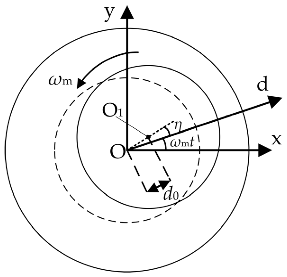
During the manufacturing of the BIPMSM, machining errors and assembly tolerances cause the rotor’s center of mass O
1 to deviate from its geometric center O, resulting in an eccentricity [
26]. As illustrated in
Figure 3, the distance between these two points is defined as
d0. The angle between the dotted line segment and the d-axis of the rotational coordinate system is
η. When the rotor rotates at the mechanical angular speed
ωm, the angle between the dotted line segment and the x-axis in the stationary coordinate system of the suspension force windings is
η +
ωmt. Due to the unbalanced vibration of the rotor, the periodic unbalance force is
Fa. The component force of the
Fa in the x-y coordinate system can be expressed as [
27]
where
Fax and
Fay are the components of the unbalanced force
Fa in the x- and y-axis, respectively.
m is the mass of the rotor,
d0 is the distance between the geometric center and the mass center of the rotor.
Suppose
xa and
ya are unbalanced vibration displacement components along the x-and y-axis. In view of the symmetry of motor structure, the stiffness of unbalanced vibration displacement along the x-axis equals that along the y-axis; thus, the unbalanced vibration displacement excited by unbalanced exciting force
Fa can be expressed as follows:
where
γ is the phase lag of the unbalanced vibration displacement relative to the unbalanced exciting force and
Am is the amplitude of the unbalanced vibration displacement component.
As shown in (6), rotor mass unbalance results in periodic vibrations, with the vibration frequency matching the rotational speed. Therefore, if the principle of proportional resonance is applied to eliminate these periodic vibration components as the signal enters the controller, vibration suppression can be effectively achieved.
2.4. Analysis of the Vibration Mechanism of the DT Effect
The unbalanced forces generated during the operation of BIPMSMs are influenced not only by manufacturing factors but also by the control process, with DT effects being the most direct cause. The DT effect arises from the introduction of dead time to prevent short circuits between the upper and lower inverter switches.
In motor control systems, the DT effect primarily arises from the switching characteristics of the inverter power devices. In motor drives, DT is introduced to prevent simultaneous conduction of the upper and lower bridge arm power devices, thus avoiding short circuits. While the DT effect prevents direct short-circuiting, it causes the output voltage during the DT period to depend on the load current direction, leading to waveform distortion, increased harmonics, and current steady-state error. As a result, the fundamental voltage is reduced, and torque and speed fluctuations occur, which degrade system precision and stability. The DT effect is essentially a nonlinear voltage error, related to the current direction, caused by both device non-idealities and protective strategies. This requires compensation algorithms or improved PWM strategies to mitigate its impact.
With conditions where the current direction remains unchanged, the voltage gain or loss caused by the dead zone effect within a single PWM cycle is
where
Udc is the DC bus voltage and
uSW is the conduction voltage drop across the switch transistor.
uD is the conduction voltage drop across the diode.
Tdead is the dead time and
TPWM is the switching period.
When the current flows from the power device to the motor in the positive direction, the value in (7) represents a voltage drop; conversely, when the current flows in the negative axis direction, the value in (7) corresponds to a voltage rise.
The phase voltage variation caused by the dead-zone voltage in (7) is transformed into the voltage in a d-q rotational coordinate system via Clark and Park transformations. The harmonics of order higher than the 12th are neglected in the equation. Its Fourier series is
where
ϴe represents the electrical angle.
When treating the motor as a resistive-inductive load, we obtain the following:
where
Rs is the internal resistance of the motor rotor.
Li is the coil inductance and
ωe is the electrical angular velocity; the impedance and phase angle are
For the BIPMSM, (9) expresses the d-q axis current increments of the torque windings as Δ
iTd and Δ
iTq, and those of the suspension force windings as Δ
iSd and Δ
iSq. The incremental expressions of the suspension force along the x- and y-axis can be derived from its mathematical model as follows:
where
As shown in (10), for the BIPMSM, DT effects introduce the 6th and 12th harmonic components into the exciting force, which are related to the electrical angular velocity. As the rotational speed increases, these harmonics induce additional vibration increments in the suspension force along the x- and y-axis. Therefore, to mitigate the vibration effects caused by DT, compensation control must be implemented.
3. Proportional–Integral–Resonance-Based Vibration Suppression Strategy
3.1. Design of the Controller
Based on the vibration mechanism analysis of the BIPMSM presented in
Section 2, an internal model is constructed within the controller to simultaneously suppress vibrations induced by rotor mass eccentricity and DT effects. The internal model of signals is represented by a set of resonant terms connected in parallel. In this design, the PI controller is connected in parallel with a modified PR controller, forming a PIR controller. Consequently, the internal model of the relevant signals is integrated into both the current and suspension force controllers. The PI controller provides DC regulation and governs the dynamic performance of the system.
The fundamental transfer function of the PR controller is
where
Kp is the proportional gain and
kr is the resonant coefficient. ω
0 is the resonant frequency.
When the angular frequency of the input AC signal is
ω0, the magnitude of
G1(
s) approaches infinity, thereby enabling zero steady-state error tracking for sinusoidal signals at the resonant frequency. However, in practical systems, the implementation of an ideal PR controller is constrained by component parameter tolerances and the limited precision of digital control systems, making it difficult to realize in both analog and digital domains. Furthermore, because the gain of an ideal PR controller decreases sharply outside the resonant frequency, it cannot effectively suppress higher-order harmonics when motor speed fluctuations cause the actual operating frequency to deviate around the resonant point. Therefore, to improve upon the ideal PR controller, the modified PR controller structure shown in (12) is adopted, whose transfer function is given by
Based on the vibration analysis of the BIPMSM presented in
Section 2, it is observed that under steady-state conditions, DT effects introduce 6th- and 12th-order harmonic components, while rotor mass eccentricity produces vibration components synchronous with rotational speed. To simultaneously suppress these periodic vibrations, three modified PR controllers with different resonant frequencies are connected in parallel to achieve targeted attenuation at the three frequencies. The transfer function of this configuration is given by
where
ωc0,
ωc1, and
ωc2 are the fundamental, 6th- and 12th-order resonant cutoff frequencies, respectively.
kr0,
kr1, and
kr2 are the resonant coefficients.
ω0,
ω1 and
ω2 are the associated resonant frequencies. Given the frequency-varying characteristics of the BIPMSM drive system, the controller must be capable of adapting to diverse operating conditions.
The Bode diagram of the modified PR controller is shown in
Figure 4.
According to the Bode diagram, the parallel connection of three modified PR controllers with different resonant frequencies can effectively attenuate signals at these frequencies. However, the Bode diagram also reveals that the controller exhibits poor performance in suppressing low-frequency signals. To enhance its performance in the low-frequency range, a PI controller is employed in parallel with the modified PR controllers.
The design of the PIR controller obtained by paralleling the controllers is shown in
Figure 5. To ensure that signal
iSd* accurately tracks signal
iSd while rejecting disturbances, the controller must guarantee robust performance. As analyzed in
Section 2, under steady-state conditions, DT effects generate 6th- and 12th-order harmonic components, while rotor mass eccentricity introduces vibration components synchronous with the rotational speed. To suppress these effects, three resonant terms are incorporated, each targeting one of the identified components. To ensure that the resonant modules adapt their respective frequencies to the correct angular frequency, the electrical angular velocity is employed as the fundamental resonant frequency. To balance design complexity with control performance, a PI controller is connected in parallel to provide steady-state accuracy and maintain essential dynamic performance.
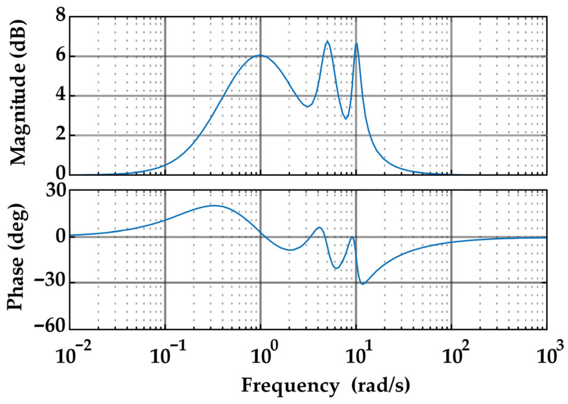
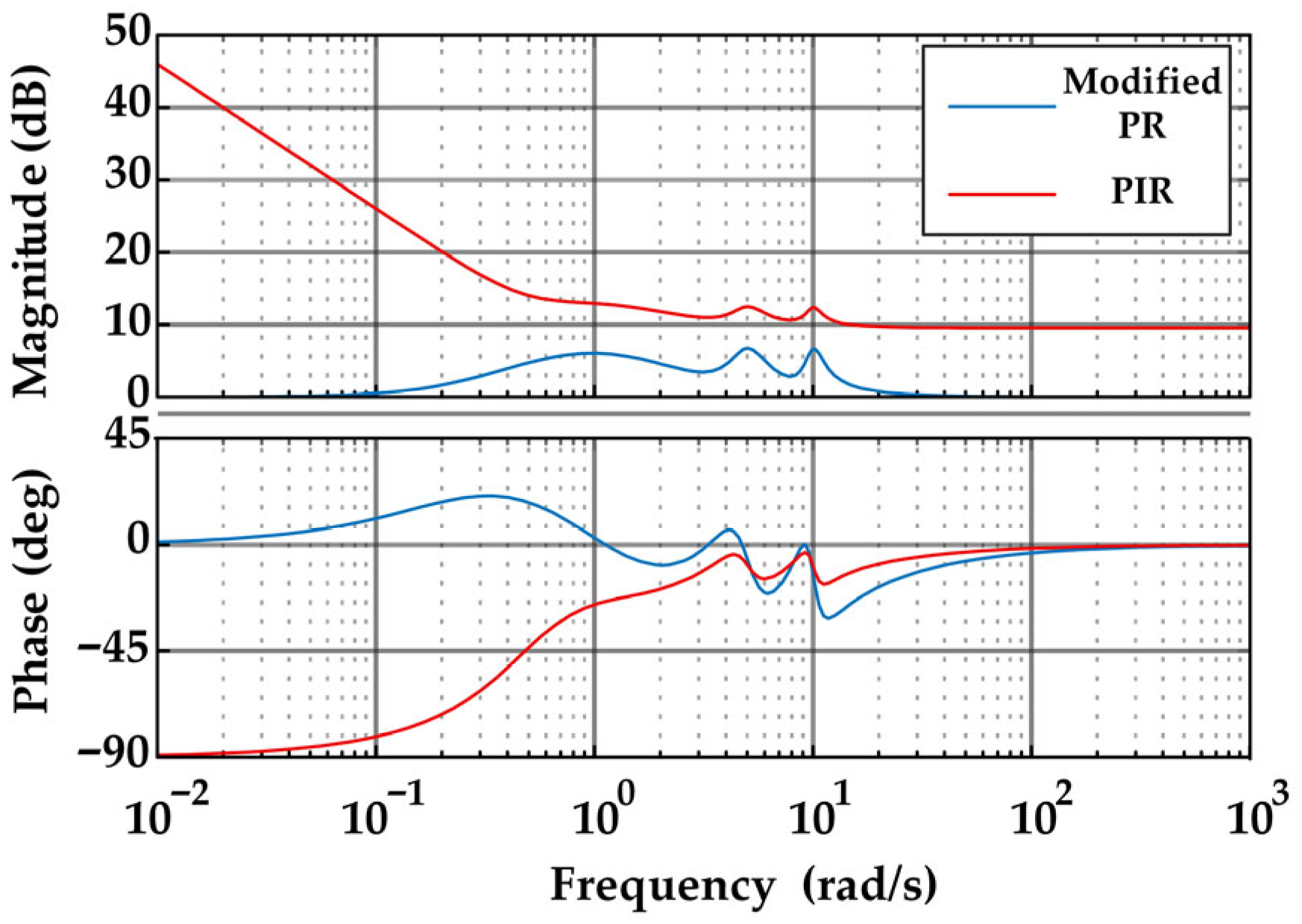
The closed-loop Bode diagram of the PIR controller obtained by paralleling the controllers is shown in
Figure 6. The Bode diagram demonstrates that, with the PI controller incorporated in parallel, the PIR controller retains its capability to attenuate complex signals at specified frequencies. Compared with the modified PR controller alone, the addition of the integral component ensures zero steady-state error under step disturbances, thereby enhancing low-frequency disturbance suppression and improving performance in the low-frequency range. When only the modified PR controller is used, suppression effectiveness declines significantly once the target frequency deviates due to grid frequency offsets or rotor speed fluctuations. By providing high gain in the low-frequency region through its integral action, the PI controller establishes the theoretical foundation and practical guarantee for steady-state accuracy and low-frequency disturbance rejection. Consequently, the PIR controller is able to effectively suppress signals even when the excitation frequency does not precisely coincide with the resonance peak, while also contributing to improved dynamic response.
Based on the preceding analysis, the PIR controller exhibits strong suppression capability. It can simultaneously attenuate signals at multiple frequencies while preserving the favorable dynamic performance of the PI controller and maintaining high robustness. As a result, motor vibrations during operation are effectively reduced, thereby ensuring stable motor performance.
3.2. Controller Parameter Tuning
The tuning of the PIR controller parameters involves adjusting both the PI and the modified PR components. The PI parameters can be tuned based on the internal model principle, while this paper primarily focuses on the tuning of the modified PR parameters.
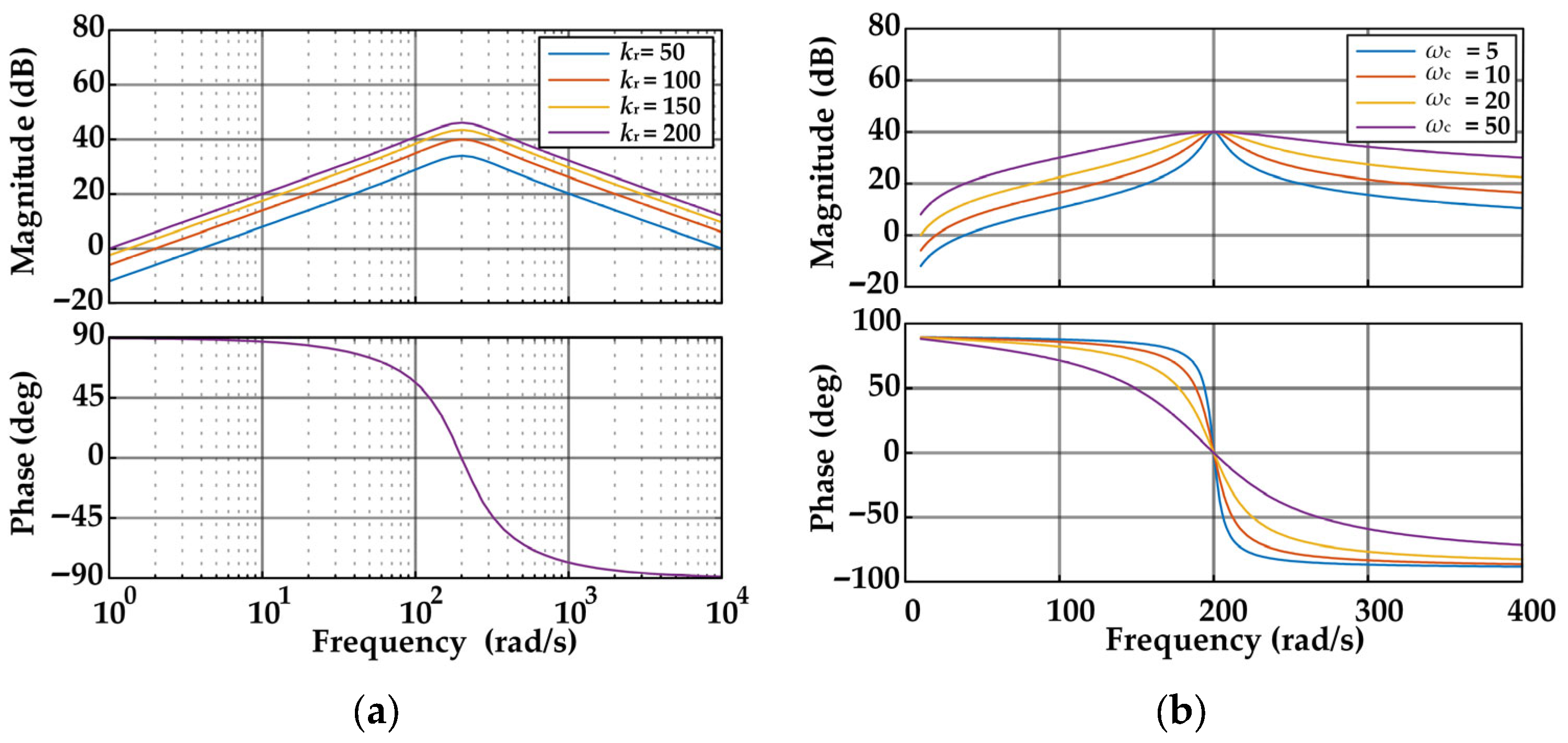
Figure 7 presents the Bode diagrams of the modified PR component under different conditions.
As shown in
Figure 7a, increasing
kr enhances the gain at the fundamental frequency, thereby contributing to the elimination of steady-state error. However, a larger
kr also broadens the bandwidth of the modified PR controller, expanding the resonance influence range and amplifying undesired signals, which is detrimental to overall system stability. In
Figure 7b, where only
ωc is varied, a decrease in
ωc increases the gain at the fundamental frequency while narrowing the bandwidth, thus improving signal selectivity. The parameter
ωc, therefore, determines the controller’s effective bandwidth.
The tuning method of the PIR controller can be summarized based on some key characteristics. Firstly, to minimize the influence of PIR on signals outside the selected frequency, an appropriate value of kr should be chosen. Secondly, to effectively suppress AC disturbances, a smaller ωc is preferred. However, excessively small ωc values may render the system overly sensitive to input frequency variations, potentially leading to instability. Thus, the selection of ωc must balance system stability with disturbance rejection capability. Parameter mismatches may also result in kr being smaller than the value determined from the BIPMSM parameters, which reduces the controller bandwidth at the selected resonant frequency and weakens its ability to reject AC disturbances. Consequently, the optimal values of ωc and kr should be selected comprehensively based on the operating conditions of the actual system.
3.3. Overall Structure of Control Methods
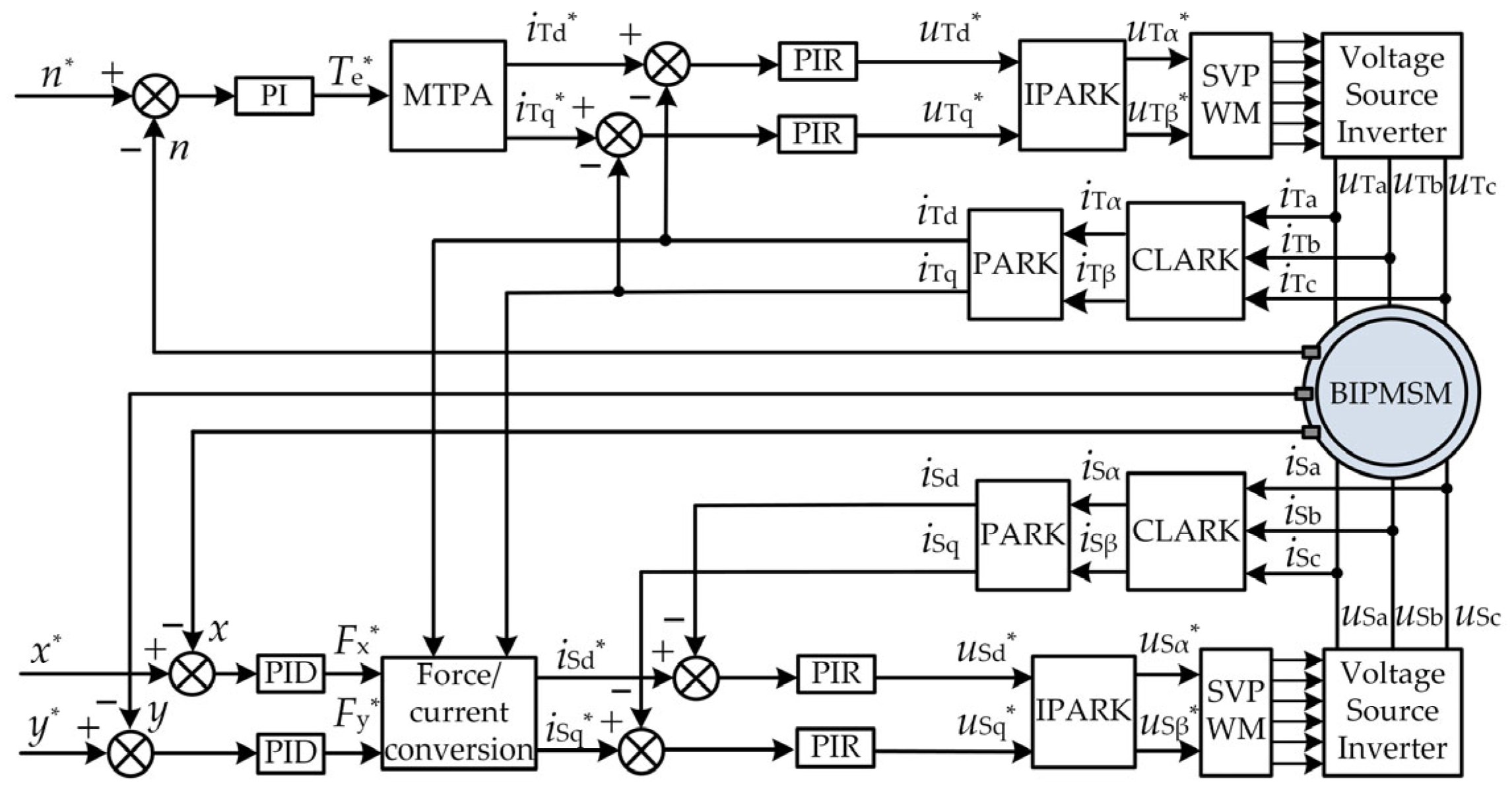
According to the control method proposed above, the overall control block diagram of the BIPMSM can be constructed as shown in
Figure 8.
The system adopts a dual-channel decoupled control structure: rotational speed and torque are generated by the main torque winding current, while radial suspension force is produced by the suspension force winding current. Both components are precisely controlled through current loops and coordinate transformations and are driven by a voltage-source inverter. This configuration ensures reliable torque output while achieving stable, contactless rotor suspension. In the torque control system of the BIPMSM, the MTPA (maximum torque per ampere) control strategy is adopted. The MTPA control, also known as the maximum torque output per unit current control, achieves the desired torque by minimizing the stator current magnitude through optimal regulation of the d-axis current. Under the condition of producing the required torque, the MTPA strategy requires only the minimum stator current magnitude, thereby reducing copper losses, alleviating the thermal stress on the inverter switching devices, and significantly improving overall system efficiency. The MTPA control method not only ensures stable operation of the torque control system but also maximizes motor efficiency while minimizing current loading. Furthermore, it exhibits strong adaptability, enabling automatic adjustment according to varying operating conditions to meet diverse performance requirements. Within this control system, the PIR controller not only guarantees accurate tracking of the fundamental current component with zero steady-state error but also effectively suppresses current harmonics and torque ripple, thereby enhancing steady-state precision and harmonic suppression capability, significantly reducing rotor vibrations.
4. Simulation on Vibration Suppression Control of BIPMSM
To verify the effectiveness and correctness of the proposed method, a simulation model of the BIPMSM is established in MATLAB/Simulink (R2022b) for analysis, with the motor parameters listed in
Table 1. Comparative simulations are conducted under identical load conditions, evaluating the performance of the BIPMSM controlled by the proposed PIR controller against that using a conventional PI controller.
The PID control parameters for the BIPMSM vector control system are shown in
Table 2. This table provides the PID parameters for the suspension force system, as well as the parameters for the torque system. The PIR controller parameters are shown in
Table 3, where the suspension force system and torque system parameters are listed separately.
A comparative simulation between the proposed PIR controller and the conventional PI controller is conducted under motor operation at 3000 r/min, with a 1 N·m load applied after 0.5 s.
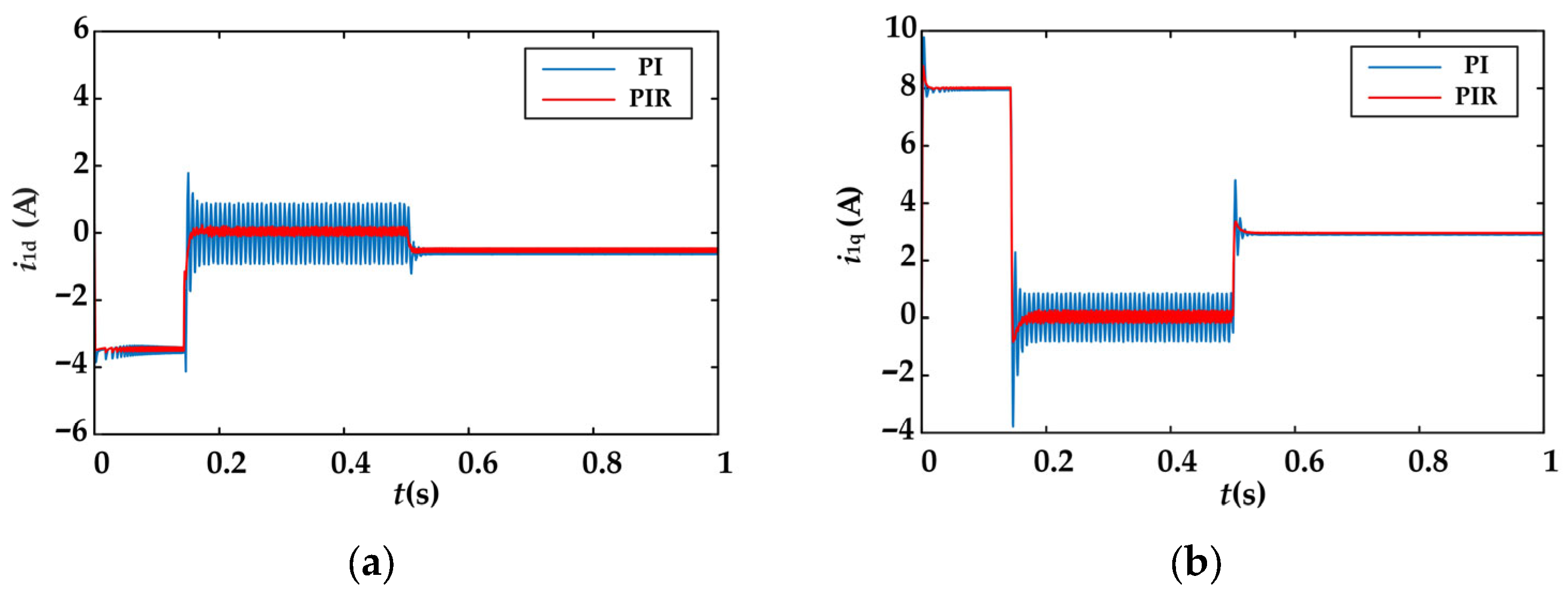
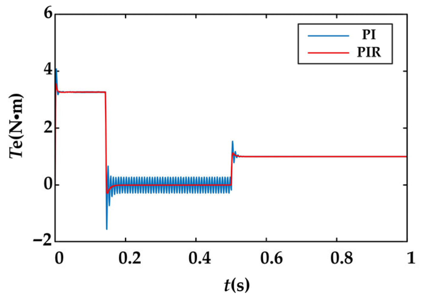
The simulation results for the harmonic pulsations of the d-q axis currents at the torque system and the corresponding torque waveforms are shown in
Figure 9 and
Figure 10. With the PI controller, the d-q axis current waveforms exhibit significant fluctuations, accompanied by large torque ripple amplitudes. Specifically, the d-axis current fluctuation amplitude is approximately 1.72 A before load application and 0.17 A after load application; the q-axis current fluctuation amplitude is approximately 1.65 A before load application and 0.03 A after load application, while the torque ripple amplitude is approximately 0.54 N·m before load application and 0.012 N·m after load application. With the PIR controller, both current waveform amplitudes and torque ripple are markedly suppressed. The d-axis current fluctuation amplitude decreased to 0.3 A before load application and 0.1 A after load application, corresponding to reductions of 82.56% and 41.18%, respectively. The q-axis current fluctuation amplitude decreased to 0.4 A before load application and 0.018 A after load application, corresponding to reductions of 75.76% and 40%. Similarly, torque ripple amplitude decreased to 0.16 N·m before load application and 0.006 N·m after load application, reductions of 70.37% and 50%, respectively. These results demonstrate that the vibration suppression strategy based on the PIR controller achieves significant attenuation of both current amplitude fluctuations and torque ripple at the torque system of the BIPMSM.
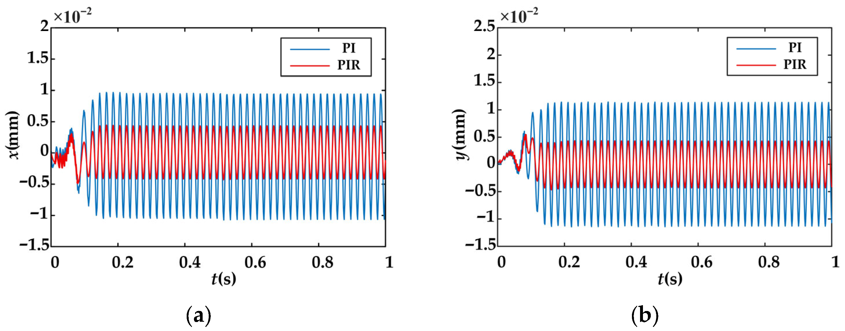
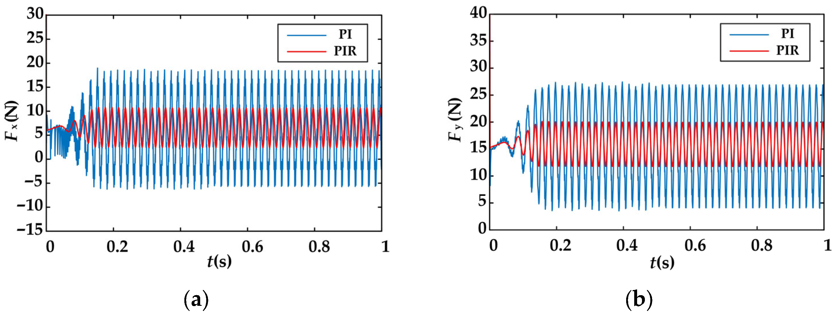
The simulation results of rotor radial displacement and radial force fluctuations of the BIPMSM are shown in
Figure 11 and
Figure 12. With the PI controller, the rotor exhibited large radial vibration amplitudes along both the x- and y-axes, accompanied by substantial radial suspension forces. Specifically, the fluctuation amplitude of the x-axis radial displacement is approximately 2 × 10
−2 mm, while that of the y-axis is approximately 2.23 × 10
−2 mm. The fluctuation amplitudes of the x- and y-axis radial suspension forces are approximately 24 N and 23 N, respectively. With the PIR controller, both radial displacement and radial suspension forces are significantly reduced. The x-axis radial displacement amplitude decreased to 0.8 × 10
−2 mmm, reduction of 60%, while the y-axis decreased to 0.81 × 10
−2 mm, reduction of 63.67%. The x-axis radial suspension force amplitude dropped to 8.45 N, reduction of 64.79%, and the y-axis decreased to 8.2 N, reduction of 64.37%.
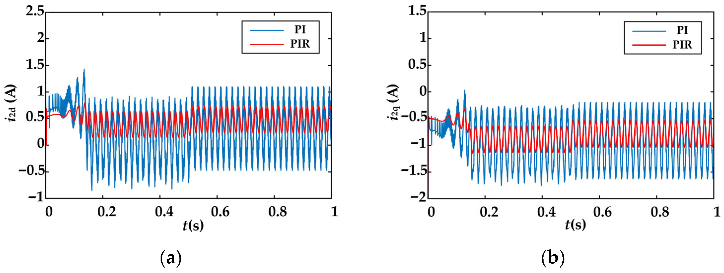
Figure 13 presents the fluctuation amplitudes of the suspension force system d-q axis currents. With the PI controller, the d-axis and q-axis current fluctuation amplitudes are approximately 1.55 A and 1.3 A, respectively. When the PIR controller is applied, these amplitudes are substantially reduced, with the d-axis current fluctuation decreasing to 0.53 A, reduction of 65.81%, and the q-axis current fluctuation decreasing to 0.59 A, reduction of 54.62%. These results clearly demonstrate that the vibration suppression strategy based on the PIR controller is highly effective in mitigating rotor vibrations in the BIPMSM.
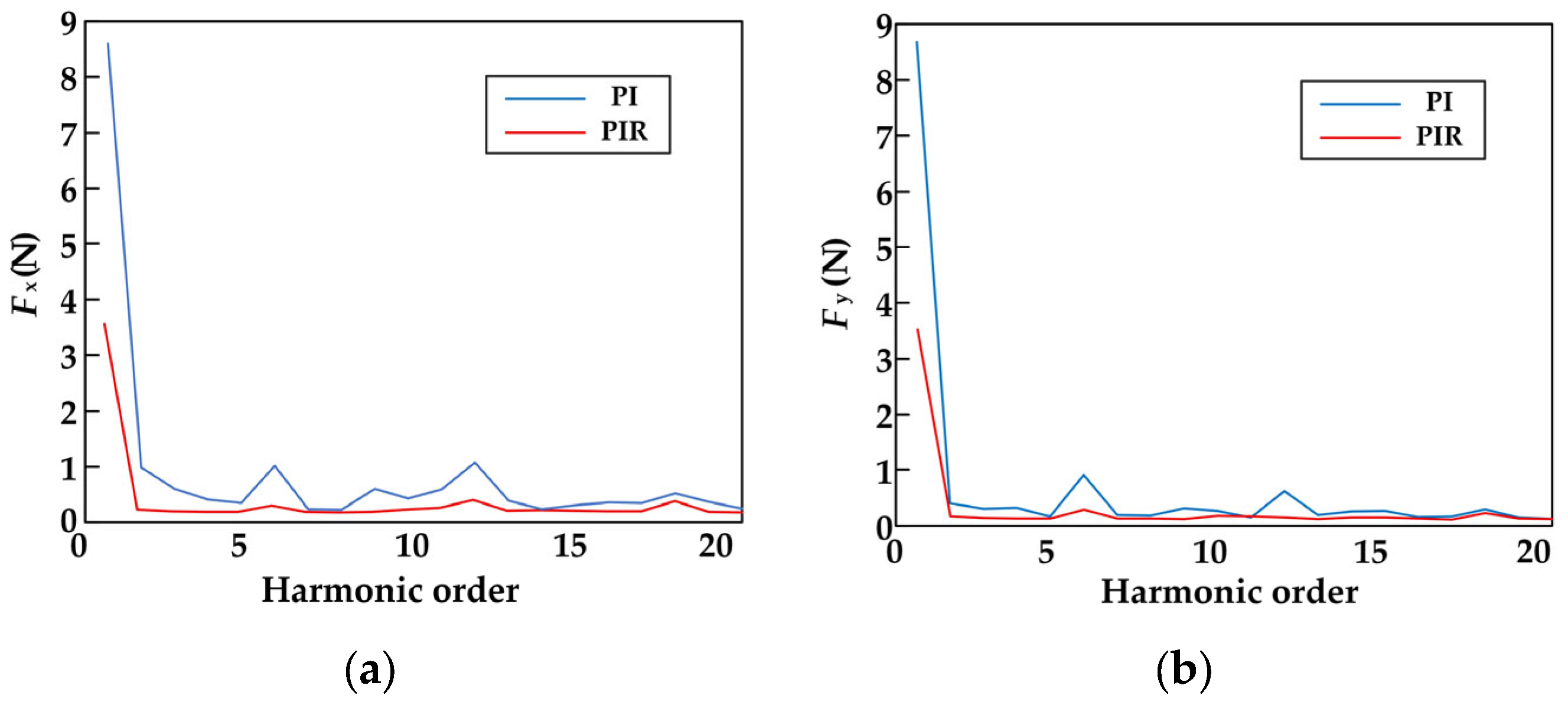
By comparing
Figure 14a,b, it can be observed that the suppression effects on the fundamental, 6th, and 12th harmonic amplitudes differ under the influence of different controllers. Firstly, the fundamental component is significantly reduced, with the PIR controller exhibiting a much lower amplitude for the fundamental harmonic compared to the PI controller. This indicates that the PIR controller results in smaller tracking errors for the fundamental sine wave, effectively suppressing the fundamental radial force. Secondly, the low-order harmonics are reduced, with the PIR controller showing lower amplitudes than the PI controller across the 2nd to 6th harmonic range. This suggests that the PIR controller has stronger suppression effects on the common low-order harmonics (fundamental 6th and 12th harmonics) in the BIPMSM, which are typically caused by DT effects and rotor mass eccentricity. Finally, there is little difference in the higher-order harmonics; for harmonics above the 15th order, the curves for both controllers are similar. This implies that the PIR controller primarily targets the resonant frequency points, such as the fundamental and low-order harmonics, and is less sensitive to high-frequency noise.
