1. Introduction
In recent years, with the rapid development of underwater information networks, marine environmental monitoring, unmanned underwater vehicle collaboration, and underwater communication in both military and civilian fields, underwater acoustic communication (UAC) has emerged as a critical enabling technology and has garnered significant attention [
1]. Compared to electromagnetic waves, sound waves have a longer propagation range in water. However, the underwater acoustic channel itself faces challenges such as limited bandwidth, strong background noise, significant multipath effects, strong channel time variability, and severe Doppler spreading [
2]. Especially in complex real-world aquatic environments, non-ideal factors such as multi-band interference, narrowband interference, and subcarrier interference often coexist, severely limiting the reliability and performance of communication systems [
3]. Therefore, research on anti-interference techniques has become one of the core challenges in enhancing the performance of underwater acoustic communication systems. Traditional anti-interference methods, such as spectrum cutting, bandpass/bandstop filtering, etc., although effective under specific interference conditions, often prove inadequate when faced with underwater communication-specific issues such as dynamic spectrum changes, multi-band interference, multipath effects, and non-ideal synchronization.
Orthogonal Frequency Division Multiplexing (OFDM) is susceptible to Doppler shift and frequency spreading [
4], and FBMC technology has gradually become an effective alternative to OFDM [
5]. FBMC achieves better localization in the time-frequency domain through carefully designed prototype filters, avoiding the use of Cyclic prefix (CP), thereby effectively improving spectral aggregation and system efficiency, making it suitable for application in underwater acoustic environments where channel frequency responses fluctuate significantly [
6]. The study [
7] analyzes the sensitivity of FBMC to residual Doppler and Inter-symbol interference (ISI) in underwater acoustic channels. As residual Doppler increases, FBMC demonstrates superior robustness compared to OFDM systems, making it a viable candidate waveform for underwater acoustic multicarrier communication.
Under the influence of spatial modulation [
8], Haas et al. proposed the preliminary concept of exponential modulation in OFDM systems [
9]. This modulation technique uses exponential information to selectively allocate the number and position of active and silent subcarriers, with active subcarriers responsible for data transmission. At the receiving end, the active status of the received subcarriers is determined by comparing threshold values [
10]. Reference [
11] introduced index modulation into the single-carrier underwater acoustic communication field and proposed a frequency-domain turbo equalizer based on sparse channel estimation. Simulation and lake experiment results validated that the proposed iterative receiver outperforms traditional frequency-domain equalization algorithms. Reference [
12] integrates IM technology into the FBMC framework to form the FBMC-IM system, which combines the spectral characteristics of FBMC with the sparse activation advantages of IM. Compared to traditional FBMC systems, the FBMC-IM system with exponential modulation is particularly suitable for communication applications in extreme environments such as low signal-to-noise ratio, strong interference, and sparse multipath [
13].
Meanwhile, the issue of interference resistance in communication systems has become a hot topic of research due to the increasingly complex environment [
14], especially in the fields of underwater acoustic communication and wireless communication, where multi-band interference, pulse interference, and broadband noise severely threaten system reliability. To address these issues, Reference [
15] proposed an adaptive interference identification and suppression method based on deep learning, which can achieve accurate interference identification and waveform restoration in low signal-to-noise ratio environments. Additionally, Reference [
16] mentions that sparse representation and compressive sensing techniques are widely used to detect sparse interference signals, enabling low-complexity interference suppression. Meanwhile, the multi-antenna technology, beamforming, and spatial filtering techniques mentioned in Reference [
17] are effective in combating interference in the spatial domain, and are particularly suitable for military communications and unmanned systems. In [
18], some studies combine cognitive radio with machine learning to achieve rapid avoidance of unknown interference through dynamic spectrum sensing, thereby enhancing system robustness.
Compared to traditional single-frequency or narrowband interference, multi-band interference typically manifests as interference signals coexisting simultaneously across multiple separate frequency bands, with each interference band potentially having distinct bandwidth, center frequency, and power levels [
19]. This form of interference not only disrupts signals across multiple frequency domains but also possesses a degree of spectral camouflage, making it difficult for traditional filtering techniques to effectively isolate the interference [
20]. Especially for multi-carrier systems, when the interference band coincides with several subcarrier frequencies, it can easily cause energy or phase distortion in the corresponding subcarriers, leading to a significant increase in bit error rate [
21].
In existing research, scholars have proposed strategies such as multi-resolution detection to address multi-band interference, but these approaches generally suffer from high detection complexity and sensitivity to interference parameters [
22]. In contrast, the interference-resistant approach based on IM offers new possibilities for addressing multi-band interference. Consequently, research on interference-resistant mechanisms has evolved from the traditional “passive interference cancelation” paradigm to a new “structured interference avoidance” paradigm. The FBMC-IM silent subcarrier interference-resistant method proposed in this paper is a concrete manifestation of this research trend.
To further improve the flexibility of subcarrier utilization, Index Modulation was introduced into multicarrier systems. By mapping information not only onto modulation symbols but also onto the activation pattern of subcarriers, FBMC-IM allows an additional degree of freedom in the frequency domain. Existing studies have demonstrated that IM can effectively suppress error propagation under multipath fading and improve error performance without additional spectrum cost. In UWA communication, IM is also capable of reducing detection complexity and improving reliability in low SNR scenarios. However, under multi-band interference conditions, traditional FBMC-IM still faces severe performance degradation since active subcarriers overlapping with interference may lead to significant BER increase at the receiver.
To address the impact of narrowband interference, various anti-jamming schemes have been proposed. Traditional approaches rely primarily on filtering-based suppression. Notch filters or adaptive frequency-domain equalizers are designed to attenuate interference energy around targeted subcarriers. Although effective when interference frequencies are known or static, these techniques may lead to signal distortion in the notch region and inevitably reduce the available communication bandwidth. Meanwhile, in dynamic UWA environments with unknown or shifting interference frequencies, filter coefficients require continuous tracking, significantly increasing computational complexity and reducing system stability.
In recent years, interference avoidance based on subcarrier scheduling and resource mapping has gained momentum. Some researchers have adopted detection-based frequency hopping strategies where active subcarriers are migrated away from interference-dominated regions. This approach improves BER performance by avoiding harmful spectral overlap. However, when interference spans multiple bands or changes rapidly, the required real-time coordination introduces additional signaling overhead and synchronization burden. Moreover, most existing works assume interference affecting a limited number of subcarriers, making them insufficient for high-intensity or dense-band jamming scenarios.
Machine learning–assisted anti-jamming methods have also been applied in OFDM and FBMC systems, enabling improved interference classification and resource management. Nevertheless, the demanding training requirements and computational complexity make such methods difficult to deploy on lightweight UWA terminals or real-time systems such as AUVs and UUVs.
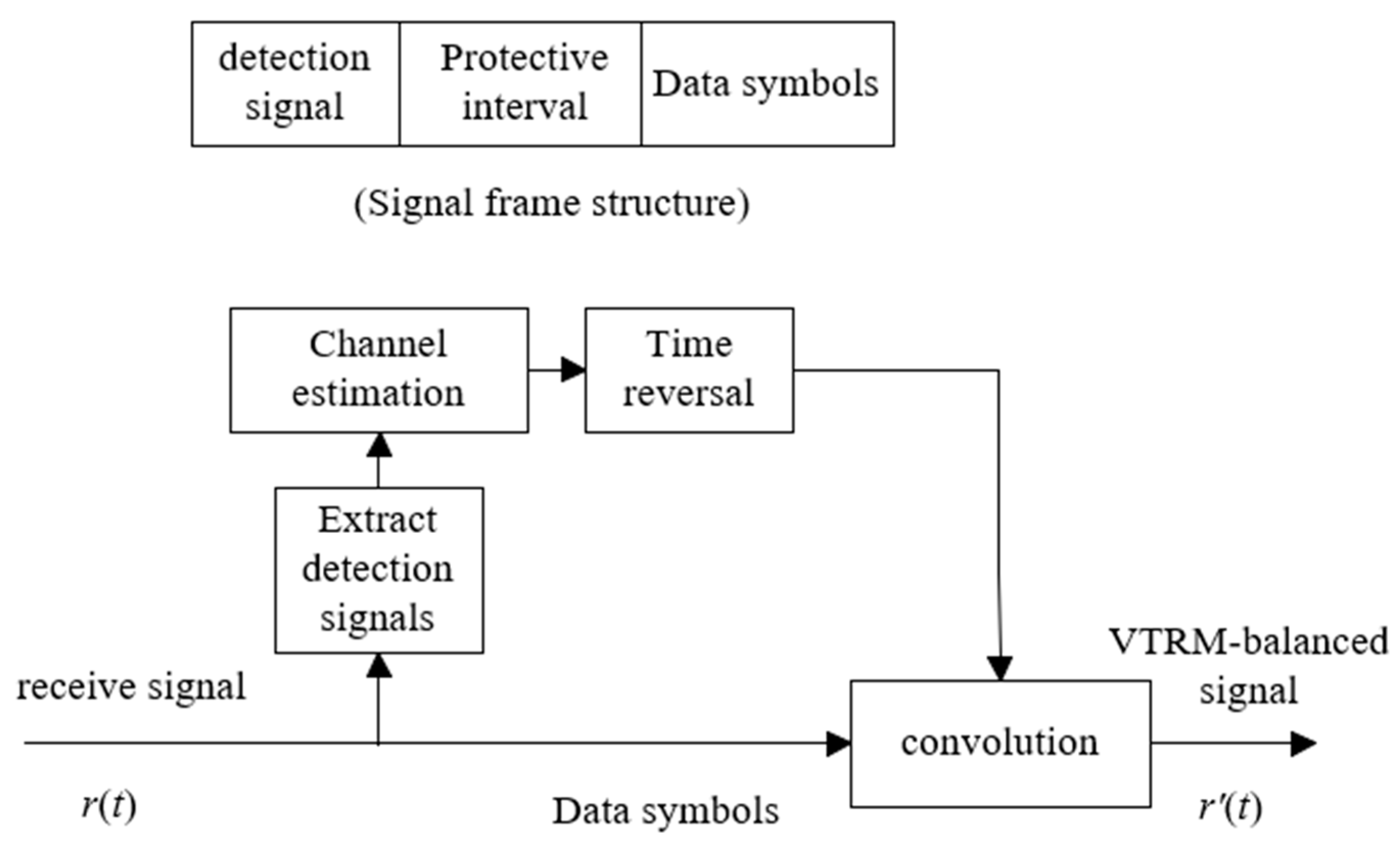
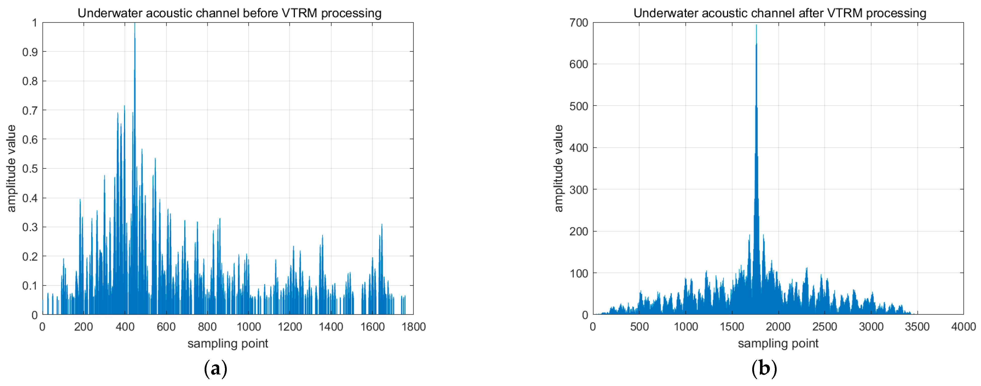
In the context of UWA multipath fading, Virtual Time Reversal Mirror equalization has emerged as an effective solution due to its ability to leverage channel reciprocity to compress energy in the delay domain. The enhanced time-domain focusing helps mitigate inter-symbol leakage and improves signal recoverability. However, existing VTRM-based solutions seldom consider the coexistence of strong multi-band interference, and performance improvements remain limited when high-power jamming dominates specific subcarriers.
Comprehensively reviewing existing research reveals several key gaps: (1) Few studies address multi-band and high-power narrowband interference that widely exist in practical UWA systems. (2) Filtering-based suppression inevitably reduces useable spectrum and system throughput. (3) Most FBMC-IM anti-jamming schemes assume static or weak interference, lacking robustness against dynamic jamming conditions. (4) Current strategies rarely combine subcarrier-level anti-interference control with channel equalization optimization. (5) A lack of systematic evaluation using real sea trial data, limiting practical applicability.
To address the above challenges, this paper proposes a novel subcarrier silence–based anti-jamming method for UWA FBMC-IM systems. Different from prior resource-hopping or notch-filtering mechanisms, the proposed method incorporates an adaptive silence mechanism where subcarriers overlapping with detected interference bands temporarily halt transmission, while IM ensures that unaffected subcarriers sustain normal data delivery. This frequency-domain separation fundamentally eliminates interference aliasing at those positions and reduces BER without the need for complex filter reconstruction. Furthermore, VTRM is integrated to suppress multipath fading, enabling the system to maintain strong anti-interference performance in realistic UWA environments.
The proposed approach is validated both through simulation and actual sea trial measurements in Bohai Sea and Dalian coastal waters, covering various channel conditions including long-delay multipath and complex band interference. Results demonstrate that the mechanism significantly enhances BER robustness while preserving spectral efficiency to the maximum extent.
Unlike traditional notch-filter-based approaches that suppress interference through deep spectral nulling—typically causing significant signal-band distortion and available-bandwidth reduction—our method avoids interference by selectively silencing only those subcarriers overlapping with the interference bands. Compared with recent FBMC-IM-based anti-jamming schemes, which usually assume limited or static interference bands and rarely consider practical underwater acoustic propagation impairments, the proposed system introduces an adaptive silence-mapping strategy supported by real-time interference-band detection, and further employs VTRM equalization to mitigate multipath-induced inter-carrier leakage. Therefore, the proposed approach not only preserves more useful bandwidth but also provides superior robustness in multi-band interference scenarios and real underwater channels. This scheme combines the characteristics of the interference spectrum distribution, setting subcarriers falling within the interference band to “silent mode,” meaning that no data is allocated during modulation, thereby avoiding bit errors caused by overlap with strong interference signals; simultaneously, subcarriers in non-interference frequency bands are utilized as effective information-carrying resources, implementing a “spectrum avoidance” data transmission mechanism. By combining this strategy of spectrum sparse activation with subcarrier silent avoidance, the system can construct a “void” structure in the interference frequency band, avoiding multi-band interference in the frequency domain, thereby achieving effective interference suppression and error rate optimization.
The main structure of this paper is as follows:
Section 2 introduces the system model used in this study, including the derivation of the FBMC-IM transmitter structure, spectral efficiency analysis, and a description of the detection algorithm.
Section 3 introduces the proposed method, focusing on interference modeling, anti-interference mechanisms, and the application of virtual time-reversal mirror channel equalization.
Section 4 provides simulation and experimental results to verify the effectiveness of the proposed method, discusses the comparison of anti-interference performance, and provides an overall discussion of the results. Finally,
Section 5 summarizes the entire paper, outlines the main findings, and proposes potential directions for future research.
The main contributions of this paper are as follows:
- (1)
A novel subcarrier silence–based anti-jamming scheme is proposed for underwater acoustic FBMC-IM systems, which does not rely on fixed notch filters or pre-known interference bands. Instead, it adaptively suppresses interfered subcarriers by utilizing the inherent flexibility of index modulation, effectively maintaining data transmission capability in the remaining interference-free spectrum.
- (2)
A practical multi-narrowband interference modeling framework is established, covering multi-band distribution, burst-type activation, and real-sea frequency characteristics. This interference representation more accurately captures hostile underwater communication conditions compared with typical additive narrowband noise models.
- (3)
An interference-aware index mapping mechanism is designed, enabling the receiver to detect interference-occupied regions and feed the information back to the transmitter for index remapping. This approach minimizes BER degradation caused by interference-signal aliasing while preserving spectral efficiency.
- (4)
Virtual Time Reversal Mirror equalization is integrated to enhance robustness against multipath spreading and frequency-selective fading. The combination of VTRM and FBMC-IM demonstrates superior channel equalization performance under underwater acoustic multipath conditions.
- (5)
Comprehensive performance verification through simulations and two sets of sea trials demonstrates a significant improvement in bit error rate under multi-narrowband interference conditions. In the simulated channel, the BER was reduced by 65–80% at a signal-to-noise ratio of 0 dB; in the Bohai Sea trials, the BER was reduced by 70–85%; and in the Dalian near-shore channel with significant dispersion, the BER improvement exceeded 90%.
In summary, these results establish a novel and practical anti-interference framework that can improve communication reliability in complex underwater environments while maintaining high spectral efficiency.
2. System Model
In this section, we mainly introduce the FBMC-IM system described in this paper, the relevant derivations of the transmitter index mapping and symbol mapping, and the spectral efficiency and detection algorithm of the FBMC-IM system.
2.1. FBMC-IM System
Taking advantage of the flexible structure of index modulation (IM), this work introduces a novel multicarrier transmission approach designed to mitigate the interference between adjacent symbols in conventional FBMC systems. The proposed technique integrates one-dimensional subcarrier index modulation with the FBMC framework, referred to as FBMC-IM.
In this scheme, the subcarriers are divided into two categories: active subcarriers, which convey constellation symbols, and idle subcarriers, which are intentionally left unused. The key idea is to incorporate the activation pattern of subcarriers as an additional dimension of modulation information. Specifically, some subcarriers are deliberately set to zero (kept silent) and carry no data, while the others remain active and transmit valid information symbols. The indices of the active subcarriers themselves serve as implicit information, effectively lowering the interference energy in the system while maintaining high spectral efficiency.
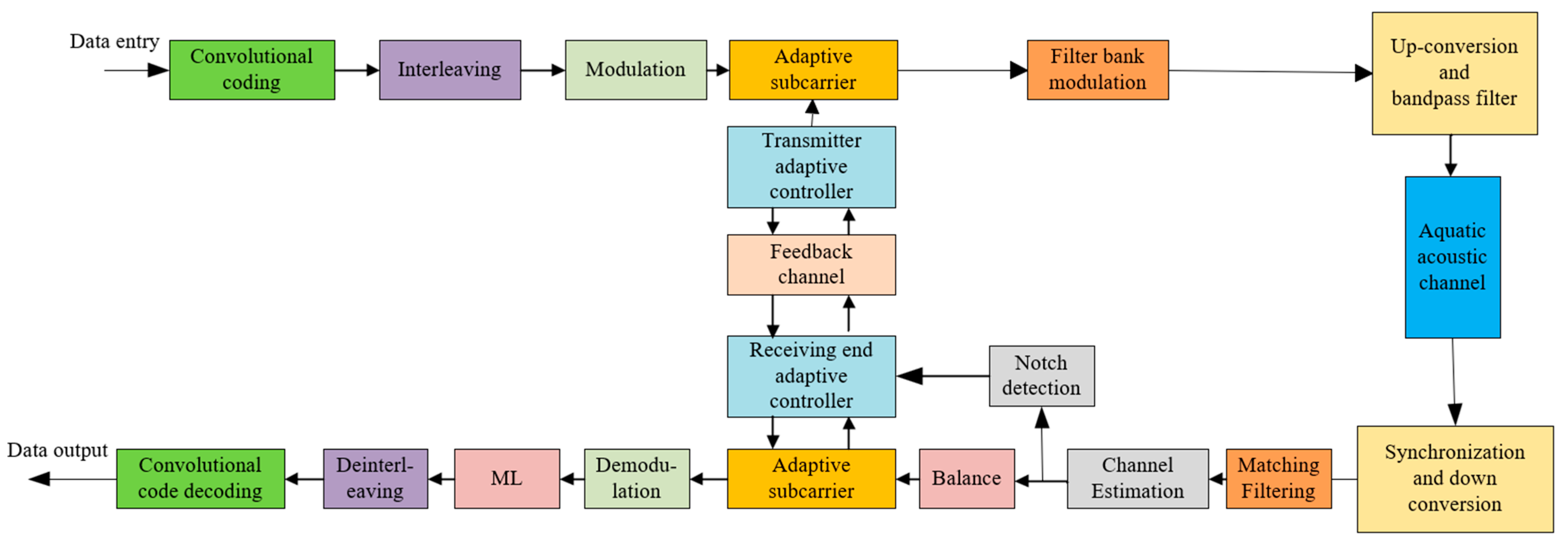
In essence, FBMC-IM achieves improved spectrum utilization without requiring extra bandwidth. Thus, an index-modulated FBMC communication framework is proposed, enabling selective deactivation (“zeroing”) of subcarriers surrounding useful symbols to alleviate inter-symbol interference. The overall system architecture of FBMC-IM is illustrated in
Figure 1.
In the transmitter of the FBMC-IM system, the input bitstream consisting of bits is first divided by the Bit Splitter into two parts: one corresponding to constellation symbol modulation and the other to index modulation. Specifically, within each group of bits, bits are processed by the Index Selector to determine the active subcarriers, while the remaining bits are mapped by the Mapper into complex-valued constellation symbols. The outputs of all groups and are then combined in the FBMC Block Creator to form the set of modulated subcarrier groups .
Each FBMC symbol is represented by a sequence of real-valued offset QAM (OQAM) components, denoted as
and
, which are filtered by the prototype filter
and its time-shifted versions
and
, where
is the symbol duration. The filtered signals are modulated by their corresponding subcarrier frequencies
and orthogonal phase terms
, ensuring the orthogonality between adjacent subcarriers. The transmitted signal can be mathematically expressed as:
where
denotes the total number of subcarriers. Finally, all subcarrier signals are summed by the operator
to generate the composite FBMC-IM transmit waveform. Once the transmitted waveform propagates through the channel and reaches the receiver, it is first demodulated using standard FBMC demodulation techniques. Subsequently, equalization and related signal recovery processes are applied to extract the received FBMC-IM symbols. These recovered symbols are then partitioned into groups and processed by the detector. By referring to a predefined lookup table, the detector identifies the mapping relationships corresponding to the activated subcarriers and their specific frequency positions. Through this process, both the index pattern and the associated constellation symbols are decoded, thereby completing the demodulation of the FBMC-IM signal.
2.2. Derivation Process of the FBMC-IM System
In the transmitter section of the FBMC-IM communication system, the
bits of information are subjected to bit splitting [
12]. To ensure that the bit allocation across groups is uniform and index mapping can be performed without ambiguity, T is defined as an even integer so that each group is assigned an equal number of bits. Each FBMC-IM symbol contains
subcarriers. The information at the transmitter is processed through splitting (primarily grouping and partitioning the total number of subcarriers, dividing the
subcarriers into
groups, with each group containing
subcarriers), and then evenly distributed across
subcarrier blocks. Thus, each subcarrier block in the FBMC-IM system contains the same number of subcarriers (
), and each subcarrier block contains
bits of information, with the relationship satisfied by the following expression:
The difference between the FBMC-IM process and the FBMC process mentioned earlier is that the bits of information in each subcarrier block of FBMC-IM will be divided into two parts for transmission. One part is used as index modulation bit information , which is mainly used to control the selection of the subcarrier index sequence (containing subcarrier position information) that needs to be activated. The other part is used as constellation modulation bit information , which is used to control the symbol information in the activated subcarrier.
To ensure generality, assume that the index sequence of the
subcarrier block’s
subcarriers carries
information bits that are sent to the index selector, where
subcarriers are selected from the
subcarriers to be activated, and
subcarriers remain silent and do not carry data. Then, the corresponding index sequence of the selected activated subcarriers can be expressed as:
Note that in the formula,
and
. The index information bit data carried by the activated subcarrier position can be expressed as:
In the formula, indicates rounding down, is the combination number, and in general, for the index number combination selected by , only the first combinations need to be rounded down.
On the other hand, the remaining
bits of information will be sent to the constellation modulator, mapped into constellation symbol outputs, which can be represented as:
In Equation (5),
,
represents a set of
-order constellation point modulation symbols, the subcarrier power normalization constraint is
,
represents the mathematical expectation, and
represents the conjugate transpose matrix. The total number of constellation modulation bits transmitted by the mapper
can be expressed as:
Here,
represents
-ary signal modulation. Generally, the number of bits transmitted in each group is
. Therefore, the total number of bits transmitted in an FBMC block can be expressed as:
The most commonly used mapping method for index modulation is the lookup table method. The lookup table method involves creating a table at both the transmitter and receiver ends, which predefines the correspondence between input bits, activated subcarrier indices, and mapped subcarrier blocks. At the transmitter, the -bit information is mapped to the positions of the subcarriers that need to be activated through the lookup table. At the receiver, the positions of the activated subcarriers are used to look up the corresponding relationship, decode the input bit information, and complete the index decoding.
As shown in
Table 1, when the subcarrier activation scheme is
and the input bits are [0 0], the corresponding activated subcarrier indices are {1, 2}, with the following implied information: it is determined to activate only the first and second subcarriers in the subcarrier block, which carry the useful symbols for transmission constellation mapping symbols. The remaining two subcarriers in the subcarrier block remain silent, do not carry useful information, and are not transmitted. Thus, the mapping relationship between the index modulation-mapped subcarrier block and the constellation symbols is obtained as: [
0 0]
T, and so on.
2.3. Spectrum Efficiency Performance Analysis of FBMC-IM Systems
In traditional FBMC systems, the desired symbols often experience interference from their neighboring symbols. By incorporating index modulation, some subcarriers can be intentionally left unmodulated—set as idle or silent—so that they do not carry any transmission data. This approach effectively reduces the interference power within the system, enhances the signal-to-interference ratio (SIR), preserves the accuracy of transmitted information, and mitigates the influence of adjacent-symbol interference.
Moreover, index modulation operates on a packet or block transmission basis. Within each transmission block, the activation pattern of subcarriers can itself convey useful information, functioning as a form of implicit data. In this way, the problem of spectral efficiency loss caused by zeroing certain subcarriers is elegantly overcome, allowing efficient utilization of available spectrum resources.
Under ideal conditions, the spectral efficiency of the FBMC system can be expressed as:
The spectral efficiency of FBMC-IM can be expressed as:
Among these, represents spectral efficiency, represents the number of different combinations of activated subcarriers selected from subcarriers, represents the number of index bits per group, and represents the number of activated subcarriers per group. denotes the mapping order, denotes the number of bits that each subcarrier can carry, denotes the average number of subcarrier blocks allocated after the subcarriers within the system symbol are split, denotes the total number of subcarriers in the system, and denotes the number of subcarriers within each subcarrier block. Since in the FBMC system, Equation (8) can be modified to: .
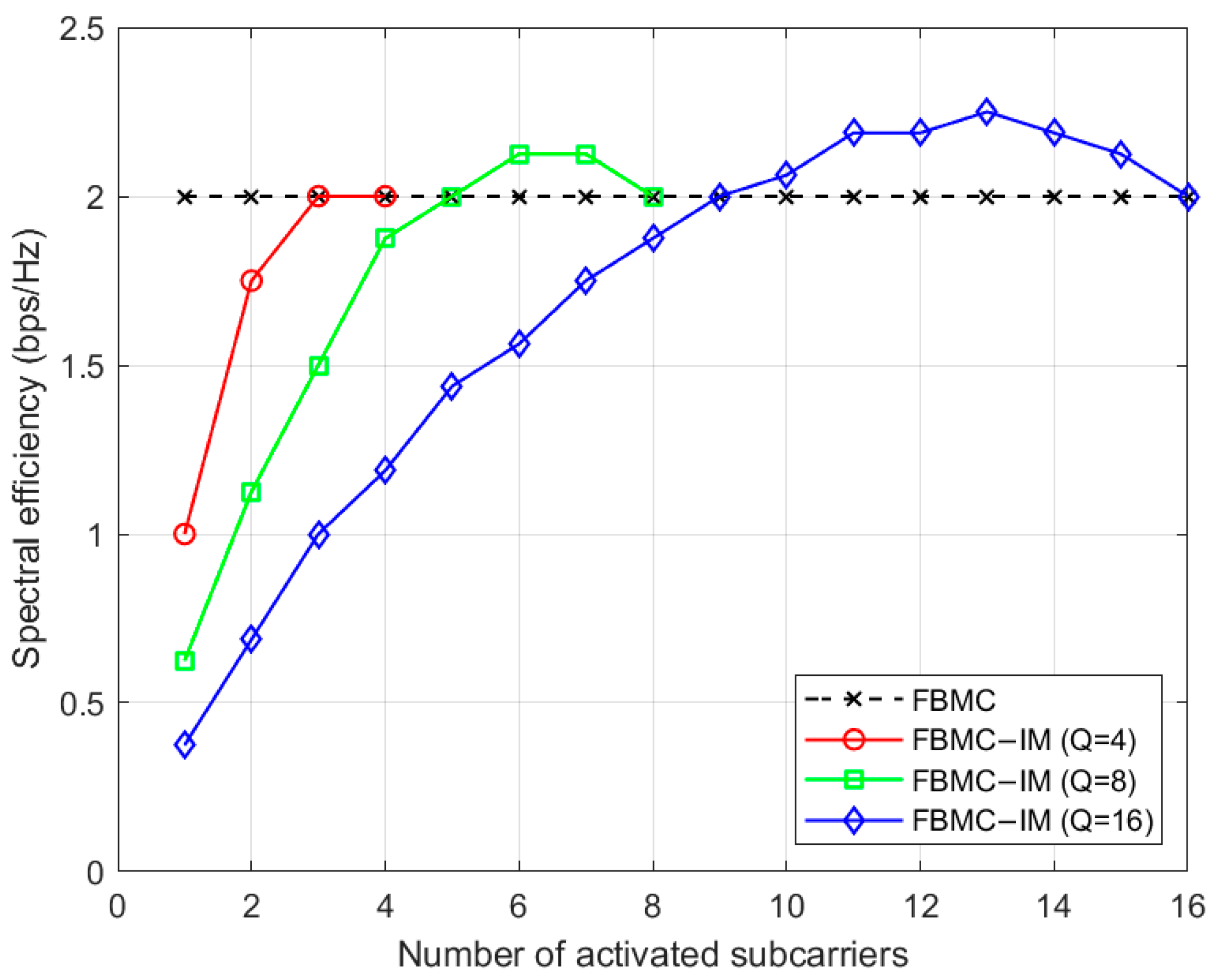
Figure 2 shows a simulation comparison of the limiting spectral efficiency of traditional FBMC and FBMC-IM (Q = 4,8,16) under ideal conditions. It can be seen that when the number of activated subcarriers in the FBMC-IM (Q = 8) system is [
5,
8], the system’s spectral efficiency is superior to that of the traditional FBMC system. In the FBMC-IM (Q = 16) system, when the number of activated subcarriers is [
9,
16], the system’s spectral efficiency outperforms that of the traditional FBMC system, and when it is [
12,
14], the spectral efficiency outperforms that of the FBMC-IM (Q = 8) system. All simulation results, including the spectral efficiency curve shown in
Figure 2, were obtained using simulation experiments in MATLAB R2024a software.
2.4. FBMC-IM System Detection Algorithm
Unlike conventional multicarrier modulation schemes, index modulation divides subcarriers into multiple groups for processing at the transmitter. Consequently, at the receiver side of the FBMC-IM system, the detection process must also be performed on a group-by-group basis, with identical detection operations applied within each group. Through this approach, both the index modulation information and the constellation modulation data of each unit can be extracted, combined, and subsequently demodulated to recover the original transmitted information.
Typical detection approaches include energy-based detection and maximum likelihood (ML) detection, among others [
23]. Specifically, the ML detection algorithm determines the most likely transmitted symbol by searching the received frequency-domain signal for symbol patterns that satisfy the constraints of Equations (11)–(13). The identified index and constellation data corresponding to each subcarrier are then integrated and superimposed, thereby completing the data detection process at the receiver end.
In Equation (11), represents the received frequency-domain signal, represents the impulse function, represents the complex frequency domain, and . From Equation (11) above, we can obtain that: through complex multiplication, the complexity of the ML detection algorithm in each subcarrier block is , and the index mapping symbol has representations, and the constellation mapping symbol has representations. It is important to note that, as shown in Equations (11)–(13), it can be seen that as the number of subcarriers in each subcarrier block and the number of subcarriers to be activated increase during the detection process, the corresponding detection algorithm complexity also increases. Therefore, when grouping subcarrier blocks, it is advisable to keep the value of as small as possible.
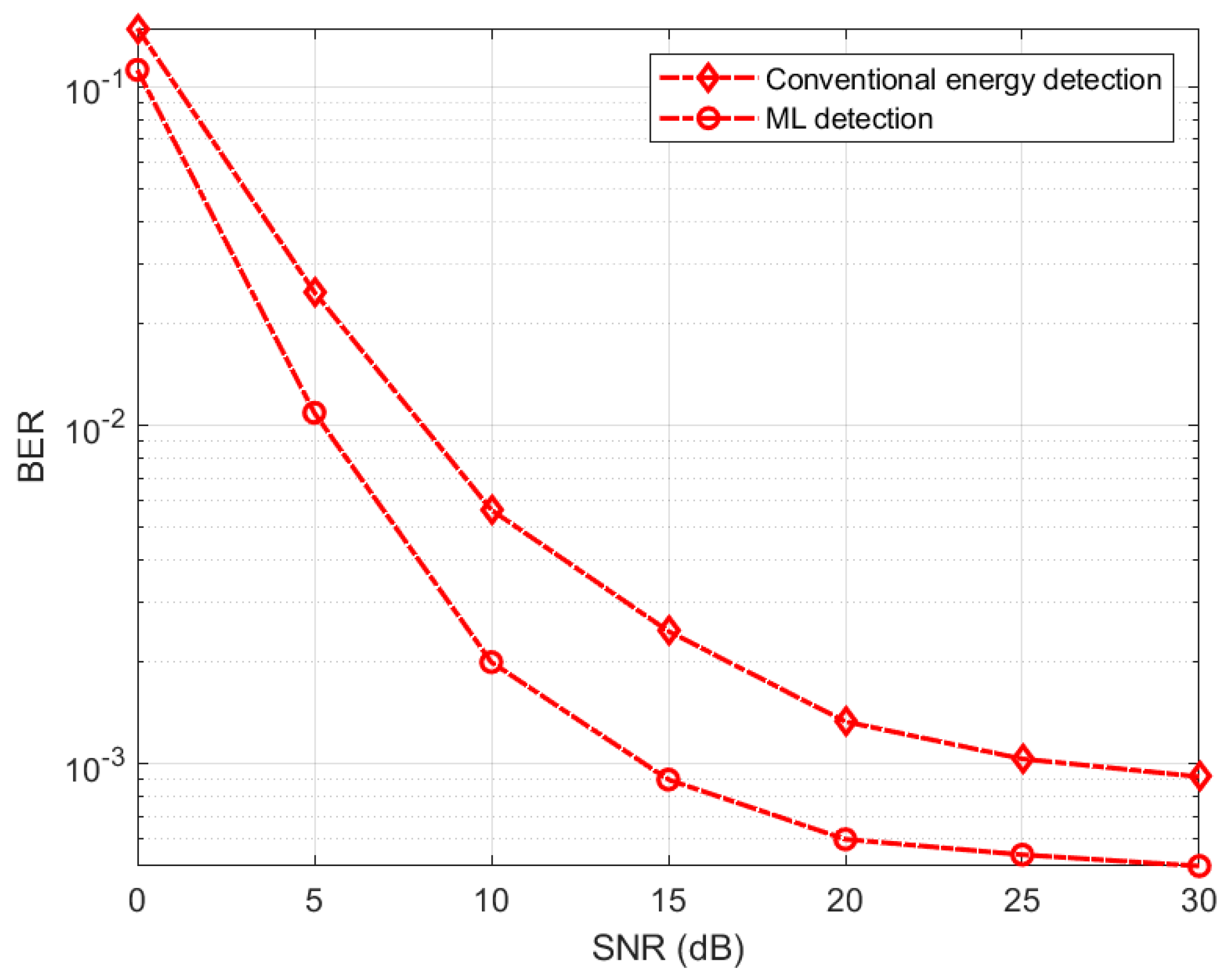
Figure 3 shows a simulation comparison of different detection algorithms for the FBMC-IM system.
As shown in
Figure 3, compared with traditional energy detection algorithms, the ML detection algorithm at the receiving end performs better in terms of bit error rate. The subsequent detection and analysis of the FBMC-IM system all use this ML detection algorithm.
4. Results and Discussion
4.1. Performance Analysis of the Underwater Acoustic FBMC System and Underwater Acoustic FBMC-IM System Without Interference
To ensure the authenticity and reliability of the experimental results, simulations were conducted using both simulated underwater acoustic channels and measured underwater acoustic channels for comparison.
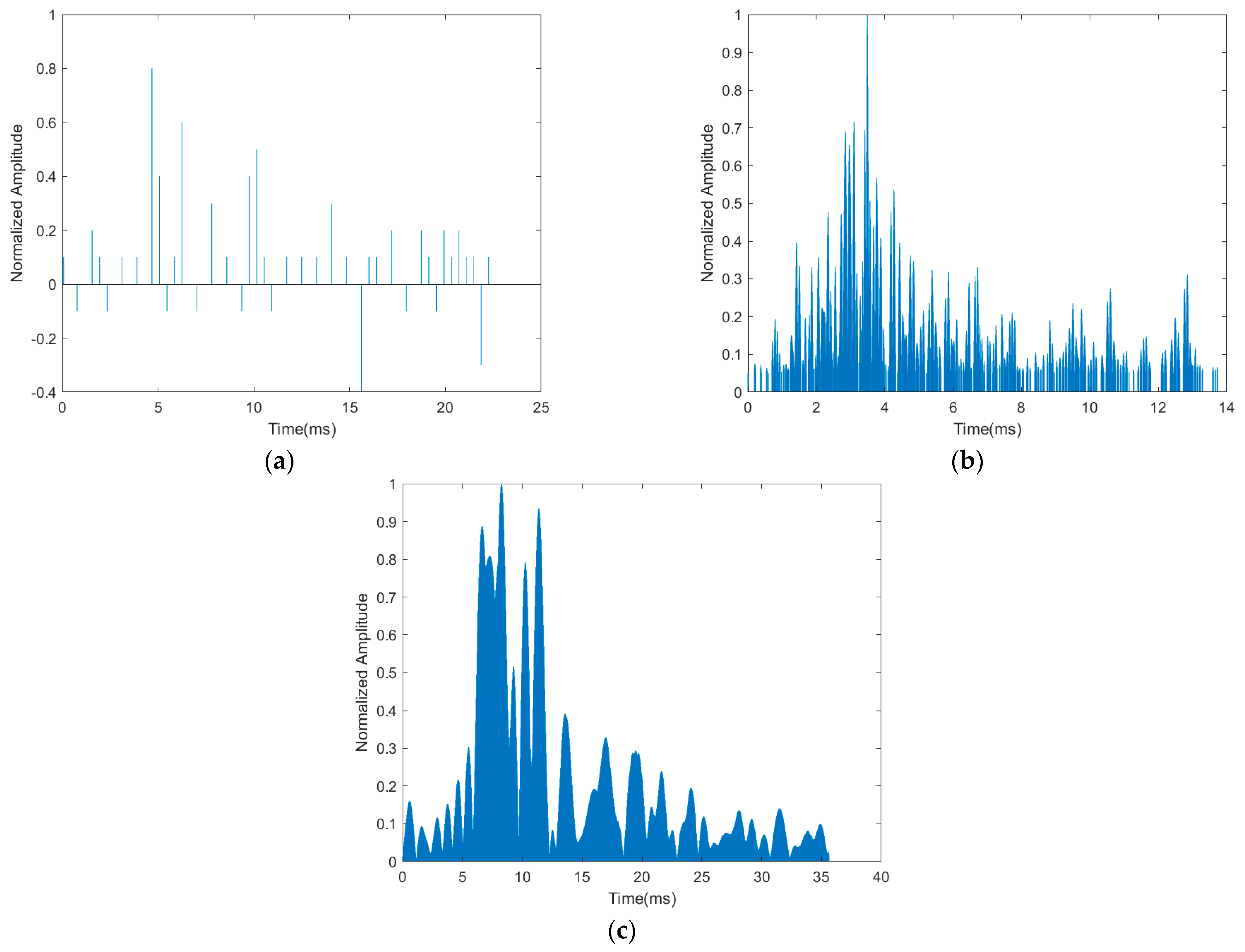
Figure 9a shows the pulse response of the simulated underwater acoustic multipath channel.
Figure 9b,c show our experimental data based on the measured underwater acoustic channel.
Figure 9b shows the channel impulse response measured at a distance of 5 km in the Bohai Sea. The experimental site had a water depth of approximately 50 m, with the transmitter transducer at approximately 15 m and the receiver hydrophone at approximately 15 m depth. During the experiment, both the transmitter and receiver vessels were in smooth wave conditions.
Figure 9c shows the channel impulse response measured in a dedicated sea area along the Bohai coast of Dalian City. The BER versus SNR performance under the Bohai Sea channel was subsequently obtained through offline simulations based on the measured channel impulse responses, where controlled additive noise was introduced to emulate different SNR conditions.
In the channel model distribution section, the delay spread distribution of the three types of channels exhibits significant scene specificity, with the following specific characteristics: The delay spread in the simulated underwater acoustic multipath scenario shows a dispersed random distribution, with no obvious main path for the multipath components. The amplitude fluctuates randomly and alternates between positive and negative, with a root mean square (RMS) delay spread of 22.1 ms and a 90% energy delay spread (EDS
90) of 24.7 ms, reflecting the highly dispersed nature of multipath energy under complex scattering conditions. The delay spread in the measured scenario at 5 km in the Bohai Sea shows a concentrated exponential decay distribution, with an RMS delay spread of 8.7 ms and an EDS
90 of 12.3 ms. 73.2% of the multipath energy is concentrated in the 0–3 ms time domain window, reflecting the weak dispersion characteristics of sparse scatterers and single multipath paths in open sea areas. The delay spread in the measured scenario in the dedicated sea area along the Bohai Sea coast of Dalian City exhibits a wide-span multi-peak distribution, with an RMS delay spread of 35.6 ms. The EDS
90 reaches 38.9 ms, and the multipath energy distribution spans from 0 to 40.2 ms. Long-delay multipath (>10 ms) energy accounts for 42.5%, which is due to the acoustic ray splitting effect caused by nearshore topography and thermocline. The experimental simulation parameters are set as shown in
Table 3.
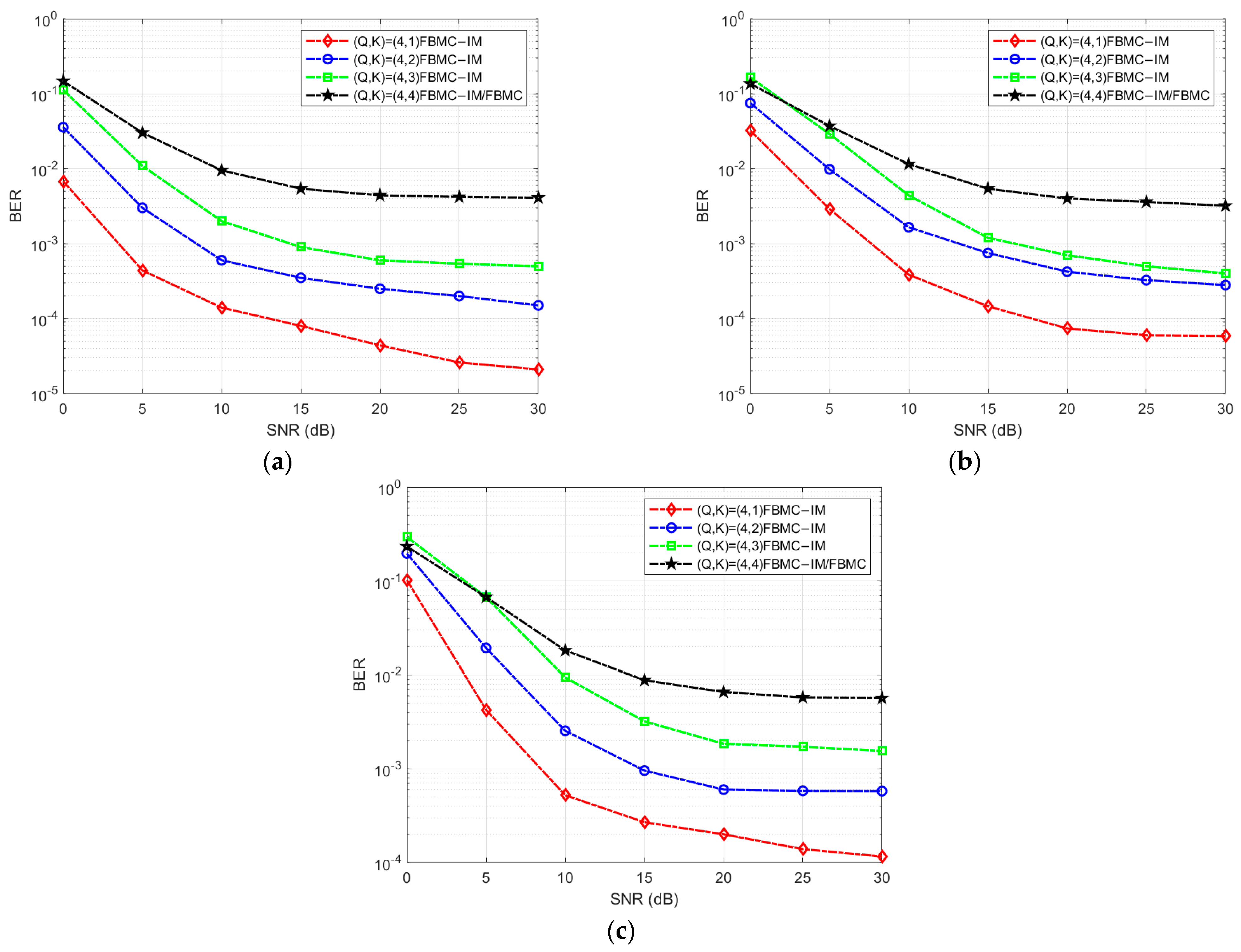
The simulation experiment first conducts a simulation analysis under conditions where the system is free from interference. It compares BER of traditional underwater acoustic FBMC and underwater acoustic FBMC-IM systems through simulation, and also simulates and compares the BER for different numbers of activated subcarriers in the underwater acoustic FBMC-IM system. Here, all subcarriers of the FBMC-IM system are divided into 128 subcarrier blocks. As shown in
Table 1, two subcarriers are selected from each group of four subcarriers for activation. The simulation also considers four cases: Q = 4, k = {4,3,2,1}, meaning that 4, 3, 2, 1 subcarrier from the 4 subcarriers in each subcarrier block to activate them, with the activated subcarriers transmitting constellation symbols in an active state and the unactivated subcarriers remaining silent to fill in empty subcarriers. When Q = k = 4, the underwater acoustic FBMC-IM system is equivalent to the underwater acoustic FBMC system. The index modulation decoding at the experimental receiver end uses ML detection, and the simulation comparison results are shown in
Figure 10.
As can be seen from the simulation results, under three different underwater acoustic channel comparisons, the error rate of the underwater acoustic FBMC system is generally higher than that of the underwater acoustic FBMC-IM system. However, compared to the error rates under the 5 km measured channel in the Bohai Sea and the simulated underwater acoustic channel, the error rate under the measured channel along the Bohai Sea coast in Dalian is relatively high. In the FBMC-IM system with index modulation, the addition of a large number of spare subcarriers significantly reduces the system BER. Additionally, as the signal-to-noise ratio increases, the number of activated subcarriers per subcarrier block decreases, while the number of unactivated subcarriers increases, resulting in a lower system BER and better performance.
4.2. Analysis of the Anti-Interference Performance of the Underwater Acoustic FBMC-IM System Under Multi-Band Interference
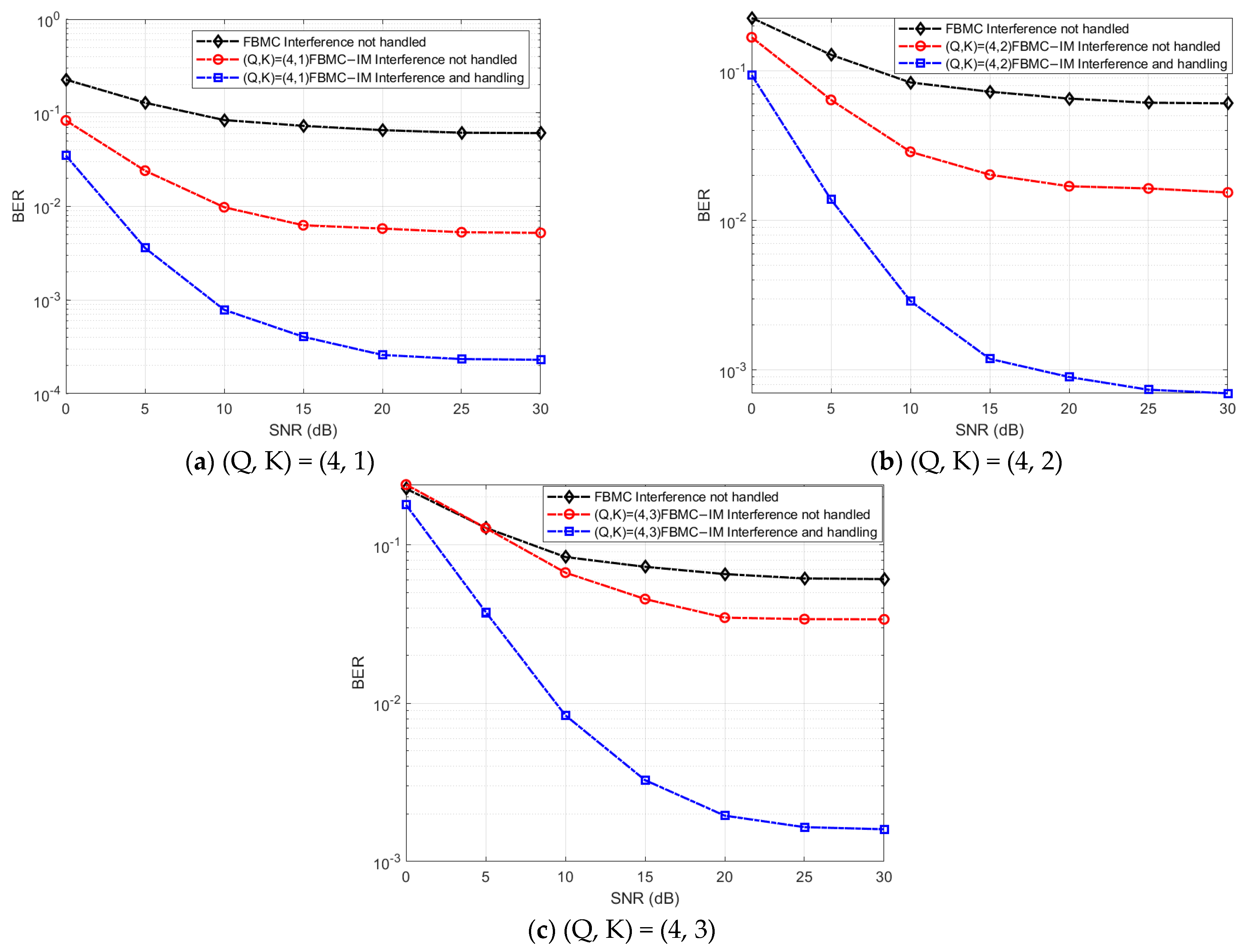
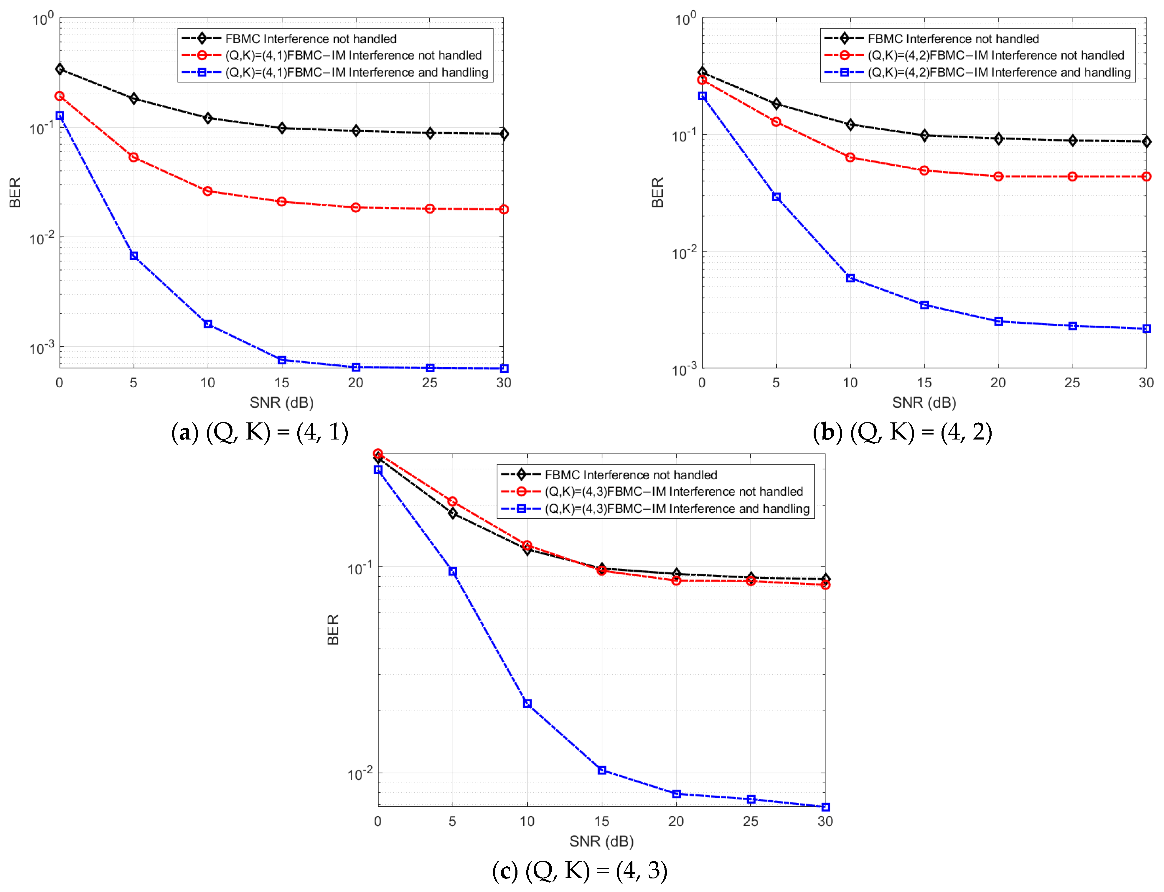
This section examines the anti-interference performance of the underwater acoustic FBMC-IM communication system under multi-band interference conditions. To highlight generalizability, simulation experiments were conducted based on the parameter settings described earlier and the simulation results of three different underwater acoustic channels. Anti-interference performance simulation experiments were performed for the FBMC-IM communication system under three different subcarrier activation selection methods. To balance interference intensity and system availability, ensuring that interference affects communication without completely disrupting it, thereby most effectively testing the system’s anti-interference performance, the signal-to-jamming ratio (SJR) for each frequency band of the multi-band interference in the underwater acoustic FBMC-IM communication system was set to 17 dB, with a total signal-to-interference ratio of approximately 12 dB. The frequency range was set to 13.6–14.4 kHz, 15.5–16.5 kHz, and 17.7–18.3 kHz, with the communication frequency band schematic diagram shown in
Figure 11.
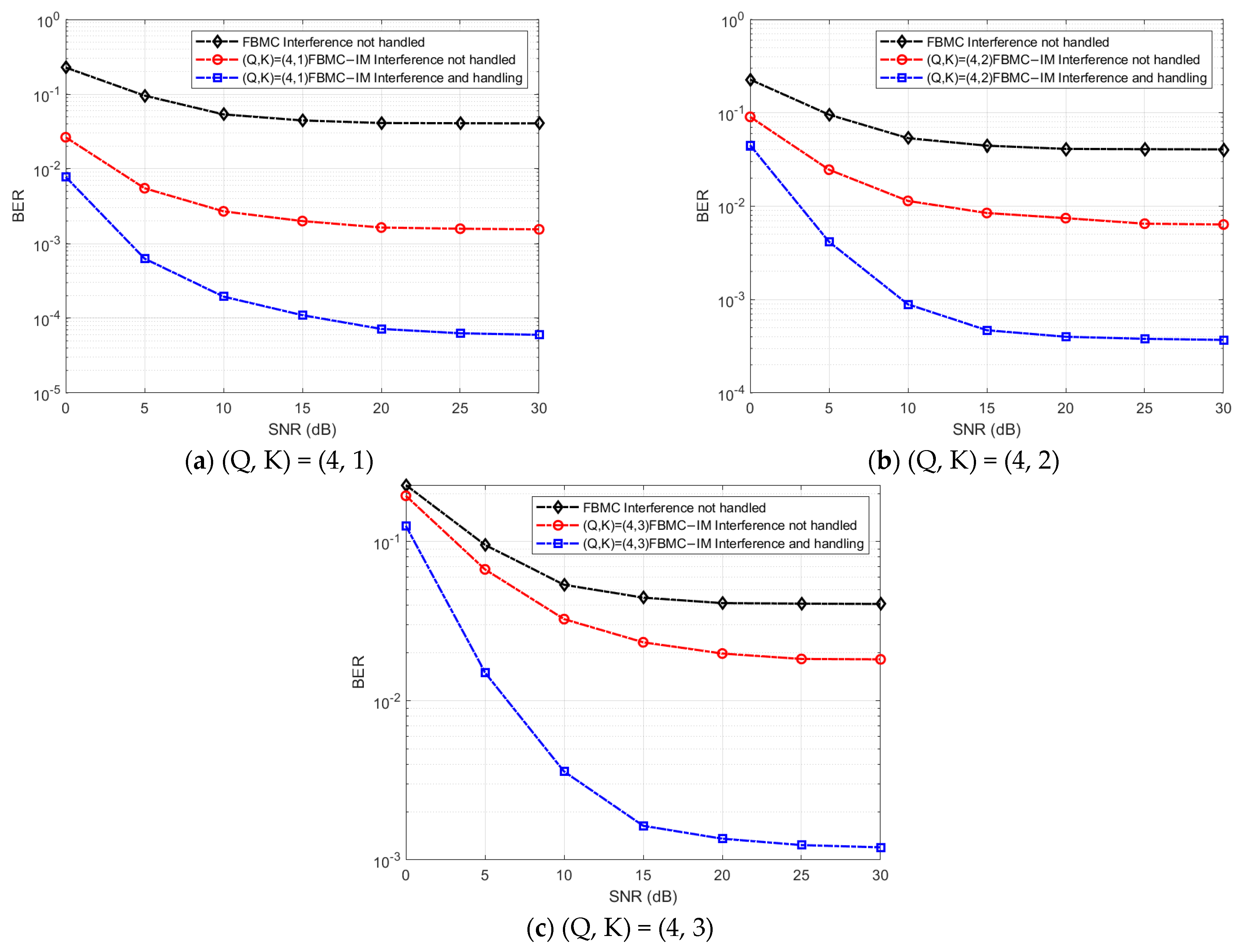
After processing the subcarriers in the overlapping region between the multi-band interference frequency band and the system communication frequency band, the simulation results of the underwater FBMC-IM anti-interference communication system under different channel environments and different subcarrier selection methods are shown in
Figure 12,
Figure 13 and
Figure 14.
As shown in
Figure 12,
Figure 13 and
Figure 14, under multi-band interference conditions, as the signal-to-noise ratio increases, the bit error rates at the receiving end of both the unprocessed underwater acoustic FBMC system and the unprocessed underwater acoustic FBMC-IM system remain relatively high, with both systems severely affected by interference. However, under unprocessed interference conditions, the bit error rate at the receiving end of the underwater acoustic FBMC-IM system is generally lower than that of the underwater acoustic FBMC system, further indicating that the underwater acoustic FBMC-IM system has a better bit error rate performance. After silently processing the subcarriers in the multi-band interference frequency band, as the signal-to-noise ratio increases, the bit error rate of the processed underwater acoustic FBMC-IM system is significantly lower than that of the unprocessed interference system. This indicates that the interference processing scheme effectively addresses the aliasing issue between communication signals and interference signals under multi-band interference conditions, significantly reducing the BER at the receiver end and greatly enhancing the system’s interference resistance. Under a 0 dB signal-to-noise ratio in the simulated underwater acoustic channel, the interference resistance performance of FBMC-IM is clearly evident. At a 0 dB signal-to-noise ratio in two measured channels in the Bohai Sea, the anti-interference performance of FBMC-IM (Q = 4, k = 1; Q = 4, k = 2) is clearly evident; however, at a 5 dB signal-to-noise ratio, the superior anti-interference performance of FBMC-IM (Q = 4, k = 3) becomes distinctly observable. Additionally, at a signal-to-noise ratio of 30 dB, in the measured channel of the dedicated maritime area along the Bohai coast in Dalian City, the acoustic channel pulse response exhibits characteristics of long-delay expansion and deep amplitude decay. When a single subcarrier block consists of 4 subcarriers and 1 subcarrier is selected for activation, the system’s receiver bit error rate is far below 10
−3; and when a single subcarrier block consists of 4 subcarriers and 2 subcarriers are selected for activation, the system’s receiver bit error rate approaches 10
−3; Especially in the measured channel at 5 km off the Bohai Sea coast, when selecting and activating 3 subcarriers out of 4 in a single subcarrier block, the system receiver error rate approaches 10
−3, and when selecting and activating 1 subcarrier out of 4 in a single subcarrier block, the system receiver error rate approaches 10
−4, demonstrating superior interference resistance performance.
4.3. Discussion
In the absence of interference, the traditional underwater acoustic FBMC system introduces index modulation. By incorporating a large number of empty subcarriers into the system, the error rate performance of the modulated underwater acoustic FBMC-IM communication system is improved. Secondly, under multi-band interference conditions in the underwater acoustic environment, by detecting the interfered communication bands in the underwater acoustic FBMC-IM communication system and feeding the results back to the transmitter, the subcarriers in the overlapping portions of the multi-band interference signals are silenced, while the unaffected subcarriers remain active and carry the communication signals. This approach avoids the interference caused by overlapping, which leads to high BER at the receiver end, thereby enhancing the system’s interference resistance. Although the proposed adaptive subcarrier silence mechanism significantly enhances the robustness of the FBMC-IM system against multi-band interference, it also introduces additional computational and feedback overhead. The required processing is mainly related to interference detection and silence decision within each block. Its computational complexity grows linearly with both the number of subcarrier blocks and candidate active subcarriers, i.e., which remains lightweight compared to traditional joint detection or adaptive filtering schemes. Moreover, only the indices of silenced subcarriers are fed back to the transmitter, resulting in very low signaling bandwidth and minimal latency due to the slowly varying nature of underwater interference. Therefore, the overhead introduced by the proposed scheme is marginal, while the BER reduction achieved (over 70–90% in both simulated and measured channels) demonstrates a highly favorable cost-performance trade-off.
While the proposed scheme significantly improves anti-interference performance, it introduces additional computational overhead during interference detection and ML detection. Current MATLAB simulations show that the system latency is within acceptable limits, but further optimization is still needed for embedded real-time implementation. Future research will focus on: lightweight interference detection and subcarrier allocation algorithms to reduce computational costs; low-complexity detection structures based on approximate ML or deep learning; and further evaluation of latency and energy consumption performance through hardware-in-the-loop testing. This will be the focus of future research to ensure further improvement in system real-time performance while maintaining anti-interference capabilities. Furthermore, this paper evaluates the computational complexity of the receive and transmit modules, including notch detection, maximum likelihood detection, and VTRM convolution. Notch detection and VTRM convolution have relatively low computational costs, while maximum likelihood detection can be significantly accelerated through algorithm optimization and parallel processing. Overall, the proposed scheme demonstrates strong real-time implementation potential on current DSP or FPGA platforms.
In the proposed subcarrier-silence FBMC-IM mechanism, system performance is closely tied to the reliability of the feedback link that conveys interference state information from the receiver to the transmitter. While current evaluations assume an ideal feedback channel with negligible delay and error, practical underwater environments may introduce propagation delays, packet loss, or feedback errors that degrade system performance. Future research will focus on enhancing feedback robustness through error-protected coding (e.g., Cyclic Redundancy Check or repetitive coding), predictive subcarrier allocation to mitigate feedback latency, and error-tolerant decision mechanisms to maintain stability under imperfect feedback. In addition, quantitative modeling of feedback delay, packet loss, and bit error rate will be incorporated, followed by validation through experimental sea trials.
Unlike conventional adaptive modulation techniques that rely heavily on accurate channel state information (CSI), the proposed subcarrier-silence FBMC-IM scheme retains robust demodulation performance even when CSI becomes unreliable due to pilot jamming in multi-narrowband interference environments. By deactivating subcarriers located within interference-dominated frequency regions, the proposed method effectively avoids rate-selection errors commonly observed in CSI-dependent adaptive modulation. In future research, we plan to integrate adaptive modulation into the FBMC-IM framework, enabling joint optimization of modulation order and the number of active subcarriers based on real-time SNR and interference sensing. Additionally, more comprehensive comparative evaluations will be conducted against representative adaptive modulation-based anti-jamming schemes to ensure fairness and strengthen the validity of the performance analysis.
Although this study primarily investigates the anti-jamming performance of the proposed subcarrier-silence-based FBMC-IM system under static underwater acoustic channel conditions, the approach exhibits significant potential for real-time applications in mobile platforms such as autonomous underwater vehicles. The FBMC-IM scheme, characterized by the absence of a cyclic prefix and flexible subcarrier activation, is expected to maintain high spectral efficiency and stable packet delivery under varying transmission ranges. Furthermore, the VTRM-assisted equalization effectively mitigates multipath-induced symbol smearing, potentially reducing retransmissions and communication latency. Future research will extend the current work to dynamic underwater environments by integrating real-time interference sensing and feedback mechanisms, evaluating packet delivery ratio and latency under different AUV movement speeds, and developing distance-adaptive carrier tracking and equalization modules. These enhancements will advance the proposed system toward a fully deployable anti-jamming solution for mobile underwater communication networks.
On the one hand, the current work primarily focuses on the design and verification of the proposed subcarrier-silence-based anti-interference mechanism for FBMC-IM underwater acoustic communication systems. However, quantitative comparisons with other representative anti-interference approaches, such as notch filtering, adaptive index mapping, and ML or compressed sensing–based suppression techniques, remain to be explored. Future studies will establish a unified simulation and experimental framework to evaluate these methods using quantitative metrics such as bit error rate, packet delivery rate, latency, and computational complexity, thereby providing a more comprehensive assessment of the proposed scheme’s performance and practical applicability.
On the other hand, in this study, the feedback link required for transmitting interference state information is assumed to be a low-rate, error-free control channel with negligible delay, which is consistent with common assumptions in underwater acoustic index modulation research. This simplification is justified since the feedback information occupies only a small fraction of the total bandwidth. However, in practical underwater acoustic environments, feedback transmission may be affected by delay, packet loss, or errors, leading to outdated interference information and degraded adaptation performance. Future work will therefore focus on integrating robust feedback encoding, error detection, and predictive mechanisms to enhance reliability under realistic channel conditions.
5. Conclusions and Future Work
This paper proposes a novel subcarrier silence–based anti-jamming scheme for FBMC-IM in underwater acoustic communication systems. A practical multi-band interference model was constructed, and an adaptive subcarrier silence mechanism was designed to selectively deactivate subcarriers that overlap with interference-dominated frequency regions. By leveraging the frequency-domain flexibility of index modulation and incorporating Virtual Time Reversal Mirror (VTRM) equalization to mitigate multipath distortion, the proposed method effectively enhances anti-jamming performance while maintaining favorable spectral efficiency.
Even under interference-free conditions, FBMC-IM inherently benefits from sparse subcarrier activation, enabling improved BER performance compared with traditional FBMC. In hostile multi-band interference environments, the proposed interference-aware subcarrier allocation strategy significantly suppresses interference spillover and prevents severe BER degradation at the receiver.
Simulation results and sea trial measurements comprehensively validate the superior anti-jamming capability of the proposed subcarrier-silence–based FBMC-IM scheme under multi-narrowband interference conditions. In a simulated underwater acoustic channel, at an SNR of 0 dB, the proposed method reduces BER by approximately 65–85% compared with the unprocessed FBMC-IM system, achieving a maximum reduction of about 88% under intensive interference. In the Bohai Sea 5 km measured channel, when adopting the configuration of Q = 4, k = 1, the BER is reduced by over 90% compared with the traditional FBMC system, and by around 70–82% when k = 3 is activated. In the near-shore Dalian measured channel with more severe multipath and delay spread, the BER improvement reaches more than one to two orders of magnitude at an SNR of 30 dB, in which a BER reduction of over 93% is achieved when k = 1. Furthermore, in multiple measured sea environments, the proposed scheme consistently achieves 50–90% improvement in anti-jamming performance over the unprocessed FBMC-IM system, demonstrating significantly enhanced communication reliability and overall robustness.
Looking ahead, future work will focus on enhancing the system’s adaptability and scalability. Specifically: (1) Development of lightweight, low-latency interference detection algorithms to support dynamic spectrum awareness under rapidly varying environments. (2) Intelligent activation pattern optimization and transmit power reconfiguration to further reinforce reliability under diverse interference types. (3) Extension of the proposed scheme to multi-user underwater acoustic networks, addressing inter-user interference and scheduling coordination. (4) Investigation of combined Doppler estimation, frequency-domain prediction, and enhanced equalization to support moving platforms such as AUVs and USVs. These research directions will broaden the applicability and engineering potential of FBMC-IM for future underwater communication systems operating in contested acoustic environments. Furthermore, while ML detection achieves optimal performance, its computational complexity increases exponentially with the number of subcarriers and modulation order, hindering real-time implementation. To address this issue, future research will focus on exploring low-complexity alternatives, such as soft-decision detection based on log-likelihood ratio and greedy search detection, to achieve a balance between performance and complexity, thereby improving the real-time feasibility and engineering application value of the system.

