Article

Evaluation of the Interactions of Multiple Inverter-Based Resources Using 2DOF Elastic Energy Equivalent System

1
School of Electrical Engineering and Automation, Wuhan University, Wuhan 430072, China
2
Hubei Engineering and Technology Research Center for AC/DC Intelligent Distribution Network, School of Electrical Engineering and Automation, Wuhan University, Wuhan 430072, China
3
State Grid Jiangsu Electric Power Company Yancheng Power Supply Bureau, Yancheng 224000, China
*
Author to whom correspondence should be addressed.
Electronics 2025, 14(22), 4479; https://doi.org/10.3390/electronics14224479
Submission received: 20 October 2025 / Revised: 11 November 2025 / Accepted: 11 November 2025 / Published: 17 November 2025

Abstract

Inverter-based resources are widely integrated into power systems, which may interact with each other and induce the risk of oscillation. This paper introduces a two-degree-of-freedom elastic energy equivalent system (2DOF-EEES) to assess interactions in power systems integrated with multiple inverter-based resources. Unlike traditional impedance-based analysis, the 2DOF-EEES intuitively represents the interactions between multiple inverters and the power network by constructing an equivalent elastic structure with two degrees of freedom. Initially, by equating parallel RLC circuits to a two-degree-of-freedom spring–damper system, the 2DOF-EEES is established. Subsequently, the 2DOF-EEES for the power system, integrated with multiple inverter-based resources, is developed by deriving analytical expressions for common and differential-mode energy. The effectiveness of this method in accurately assessing the oscillatory stability of the system is validated through time-domain simulation. The results further reveal that the differential-mode energy influences the common-mode energy via the equivalent elastic structure in the 2DOF-EEES, thereby affecting the interaction between the wind farm and the network.

1. Introduction

Inverter-based resources (IBRs) are widely integrated into power systems for environmental protection, which may interact with each other and induce the risk of oscillation [1,2,3,4]. The sub-synchronous control interaction (SSCI), as one type of oscillation between wind farms and the power grid, is analyzed by aggregating the dynamics of multiple wind farms. This follows the assumption that multiple wind farms are homogeneous and connected in parallel to the ideal power grid [5,6,7]. Some single-generator equivalent models have thus been proposed in many power system studies to enable a fast assessment of wind farm performance and the impact on the grid [8,9,10]. However, in practical wind power systems, the wind farms are heterogeneous, indicating that the operating conditions and the parameters of wind farms are different [11]. Therefore, it is also significant to reveal the interaction between wind farms on the oscillatory stability of practical wind power systems [12,13,14].
Eigenvalue analysis [15,16,17,18] and impedance-based analysis approaches [19,20,21] have been used to analyze the interaction between the generator and the grid. As for the former approach, Ref. [15] defines the overall participation factor for each equivalent generator in a mode to identify the interactive mode and specify which generators dominantly contribute to the interactive mode. In [16], the multi-machine wind farm is represented in the state space to evaluate oscillations stemming from its spatial arrangement. In [17], the impacts of various parameters as well as operating conditions on those oscillation modes are investigated. In [18], a state-space model of the synchronous generator–DFIG system is derived, and eigenvalue analysis is employed to identify the critical modes, based on which a sliding-mode controller is proposed that effectively damps the low-frequency oscillations. However, the physical meaning of interactions is difficult to reveal with the calculation of modes and participation factors. The latter impedance-based analysis approach can provide part of a definite physical meaning for such interactions. In [19], the interaction mechanism of identical paralleled inverters is revealed through the impedance modeling approach based on separate transfer functions. In [20], a clustering-based model is proposed to evaluate the interaction among differently parameterized generators by corresponding transfer function matrices. In [21], a DFIG-based frequency-domain impedance model considering RSC control under small-signal perturbations is developed in a three-phase stationary coordinate system.
The works mentioned above are based on the frequency-domain approach; the effectiveness of such an approach is affected by the selection of the fixed operating point for the system. However, the interactions in practical wind farms are affected by various operating conditions, including wind speed, types of online wind turbines, parameters of the converter controllers, etc. Such various operating conditions lead the operation points of the system to keep on changing. Ref. [22] reveals that the change in SSO frequency has a great influence on the suppression effect of the resonance controller. To tackle this issue, energy-based analysis approaches are used to evaluate the interactions in the wind power system. Refs. [23,24] evaluate the transient energy during the interaction by defining the dissipation intensity according to the Lyapunov stability theory. In [25,26], the single-degree-of-freedom elastic energy equivalent system (EEES) is established to analyze the control interaction in the wind power system from the perspective of elastic energy exchange and dissipation. The online dissipated energy criterion and potential energy condition are then developed for evaluating the interaction. However, the existing energy-based analysis approach only evaluates the generator and grid interaction. The other interaction among the IBRs has not been revealed from the view of energy, which may also affect the oscillatory stability of the system. Recent studies have primarily focused on frequency-domain impedance modeling [21,22] or aggregation-based stability analysis [19,20]. Although these methods effectively identify resonance conditions and interaction modes, they rely on linearized models around fixed operating points, which limit their ability to capture time-varying dynamics. Energy-based methods [23,24,25,26] have provided a physical interpretation of oscillatory energy exchange but are generally restricted to single-generator or homogeneous systems. Hence, there remains a need for an energy-based model that can reveal both grid–IBR and IBR–IBR interactions in heterogeneous multi-inverter systems. The proposed two-degree-of-freedom elastic energy equivalent system (2DOF-EEES) addresses this gap. Unlike conventional impedance-based or eigenvalue analysis approaches, which focus primarily on small-signal interactions at fixed operating points, the proposed 2DOF-EEES establishes a dynamic energy-based representation capable of analyzing both inter-inverter and inverter–grid couplings under variable conditions. Furthermore, compared to single-generator equivalent models that aggregate all inverters into one homogeneous source, the 2DOF-EEES retains the heterogeneity of individual inverters by introducing two energy coordinates—common and differential—thus providing a more accurate and physically interpretable model for interaction analysis. In fact, the single-degree-of-freedom EEES reveals the interaction between the wind power system and the grid through an equivalent single spring-damping branch. At this point, it is considered that each wind farm in the wind power system is homogeneous and can be aggregated. When different wind farms within the wind power system are heterogeneous (including the shunt devices) and cannot be aggregated, a new model is required to describe the interaction between the wind power system and the grid, as well as the interaction between each wind farm within the wind power system. The contributions of this paper are summarized as follows:
(1)
The 2DOF-EEES is proposed to describe the interactions in the power systems integrated with multiple IBRs in real time.
(2)
The 2DOF-EEES can decouple the interactions of the IBRs to the grid and IBR to the IBR. This is achieved by calculating the work performed in the direction of the common branch and in its vertical direction for the 2DOF-EEES, which is defined as the common-mode energy and differential-mode energy.
(3)
The existence of the differential-mode energy will affect the common-mode energy through the equivalent elastic structure in the 2DOF-EEES, thus affecting the interaction between the wind farm and the network.
The main structure of this paper is summarized as follows: Section 2 proposes the 2DOF-EEES, which is the basis for modeling systems with multiple paralleled generators. Section 3 establishes the 2DOF-EEES for the power systems integrated with the IBRs. Section 4 simulates an example system with multiple doubly fed induction generator (DFIG)-based wind farms and STATCOM to verify the effectiveness of the proposed model and the accuracy of the stability analysis. Section 5 concludes the paper.

2. Proposed 2DOF Elastic Energy Equivalent System

The variables used in this paper, along with their definitions, are provided in Appendix A (Table A1). Assuming that the oscillatory system is composed of multiple RLC branches connected in series or parallel and the current of different branches has its phase angle β_, the SDOF-EEES in [25] is incapable of modeling the aforementioned characteristics. Alternatively, as for the parallel RLC branches shown in Figure 1a, the nth RLC branch is selected as the common branch, and its current phase angle is defined as βn_n, whose value is defined as zero. In addition, the current phase angle deviation between the common branch and other RLC branches is defined as βi_n.
Then, the current phase angle deviation βi_n is analogized as the angle deviation αi_n for the spring–damper branches. This leads to the establishment of the two-degree-of-freedom (2DOF) EEES, whose structure is shown in Figure 1b. A mathematical comparison between 2DOF-EEES in Figure 1a and traditional impedance models in Figure 1b is shown in Table 1.
Remark: The significance of the 2DOF-EEES is as follows: the 2DOF-EEES provides a new reference frame for analyzing the oscillation in multiple branches, which can be used to evaluate the energy exchange and dissipation among different branches in the horizontal and vertical directions. This is achieved by calculating the work Wh and Wv (i.e., the work performed in the direction of the common branch and in its vertical direction) of the 2DOF-EEES (given in Equation (1)) during the oscillation. The work, Wh and Wv, performed over a while is defined as common-mode energy and differential-mode energy, respectively. In Equation (1), the dissipated work, Wh_d and Wv_d, reflects the damping performance of the 2DOF-EEES in the horizontal and vertical directions, respectively. When the value of the Wh_d and Wv_d is larger than zero, it indicates that the damping characteristics of the 2DOF-EEES are positive in the horizontal and vertical directions, and vice versa. In addition, the damping contribution induced by each branch can also be evaluated by separating the dissipated work Wh_d and Wv_d according to the physical structure of 2DOF-EEES. For instance, the damping induced by branch 1 (as shown in Figure 1b) in the horizontal and vertical directions can be expressed as Equation (2), where Wv_d1 and Wh_d1 are the dissipated work performed by branch 1, reflecting the damping contribution of branch 1 on the vibration of the 2DOF-EEES in the horizontal and vertical directions, respectively. Meanwhile, the work related to the potential energy (i.e., Wh_p and Wv_p) reflects the resonant condition of the 2DOF-EEES in the horizontal and vertical directions, respectively, which is used to identify the resonant condition for the 2DOF-EEES. When Wh_p or Wv_p is close to zero, it means that the resonant condition is satisfied in the horizontal or vertical directions, and vice versa. The horizontal and vertical directions in the 2DOF-EEES correspond to distinct physical processes: the horizontal (common-mode) direction represents collective energy exchange between the inverter cluster and the power grid, while the vertical (differential-mode) direction reflects relative energy exchange among parallel inverters. Identifying which direction exhibits oscillation helps determine whether instability originates from grid interaction or mutual inverter coupling.
W h = i = 1 n Δ F i cos ( π α i _ n ) d Δ l i cos ( π α i _ n ) = W h _ d + W h _ p = i = 1 n cos 2 ( π α i _ n ) ω m D i Δ l i 2 d Δ θ e g + i = 1 n cos 2 ( π α i _ n ) 1 2 k i Δ l i 2 l 0 l = i = 1 n cos 2 ( π β i _ n ) R i Δ I i 2 d Δ θ e g + i = 1 n cos 2 ( π β i _ n ) 1 2 X i ω e Δ I i 2 I I 0 W v = i = 1 n Δ F i sin ( π α i _ n ) d Δ l i sin ( π α i _ n ) = W v _ d + W v _ p = i = 1 n sin 2 ( π α i _ n ) ω m D i Δ l i 2 d Δ θ e g + i = 1 n cos 2 ( π α i _ n ) 1 2 k i Δ l i 2 l 0 l = i = 1 n sin 2 ( π β i _ n ) R i Δ I i 2 d Δ θ e g + i = 1 n sin 2 ( π β i _ n ) 1 2 X i ω e Δ I i 2 I I 0
where αi_n is the angle deviation for the ith spring–damper branch. βi_n is the current phase angle deviation between the common branch and ith RLC branch. Fi and li are the force and deformation of the ith branch. Wh and Wv are the work performed in the direction of the common branch and in its vertical direction. Wh_d and Wv_d are the dissipated energy of the 2DOF-EEES in the horizontal direction and vertical direction. Wh_p and Wv_p are the potential energy of the 2DOF-EEES in the horizontal direction and vertical direction. θeg is the voltage phase deviation of the RLC branch. Di and ki are the damping and stiffness coefficients of the ith equivalent spring–damper branch. ωm and ωe are the angular frequencies of the mechanical system and series RLC circuit, respectively. I0 and I are the initial and real-time RMS values of the branch current. Ri and Xi are the resistance and reactance of the ith series RLC branch.
W v _ d 1 = sin 2 ( π α 1 _ n ) ω m D 1 Δ l 1 2 d Δ θ e g = sin 2 ( π β 1 _ n ) R 1 Δ I 1 2 d Δ θ e g W h _ d 1 = cos 2 ( π α 1 _ n ) ω m D 1 Δ l 1 2 d Δ θ e g = cos 2 ( π β 1 _ n ) R 1 Δ I 1 2 d Δ θ e g
where Wh_d1 and Wv_d1 are the dissipated energy of branch 1 in the horizontal direction and vertical direction.
In conclusion, two criteria are developed to determine the occurrence of the oscillation in the horizontal direction or the vertical direction:
(1)
The dissipated work of the 2DOF-EEES is negative.
(2)
The work related to the potential energy of the 2DOF-EEES is close to zero. In the next section, the proposed 2DOF-EEES is applied to analyze the SSCI.
In systems with multiple parallel generators, each generator branch contributes to the total common- and differential-mode energy of the 2DOF-EEES. The two criteria, therefore, indicate whether energy exchange among these generators leads to collective oscillations. A negative dissipated work identifies insufficient damping across branches, while near-zero potential energy indicates resonance coupling. Together, they help determine oscillation risks in multi-generator systems.
The establishment of the 2DOF-EEES model is based on the following assumptions: (1) inverter and grid dynamics are linearized around their steady-state operating points; (2) high-frequency switching harmonics are neglected, as their influence on sub-synchronous oscillations is minimal; (3) the grid voltage is assumed to be quasi-stationary within the analyzed frequency range (5–45 Hz); and (4) mutual coupling among inverters is represented by equivalent RLC branches. These assumptions are standard in small-signal and energy-based modeling [23,24,25,26] and are validated by the simulation results in Section 4, which align closely with time-domain simulations of the full nonlinear system.

3. The 2DOF-EEES of the DFIG-Based Wind Farms

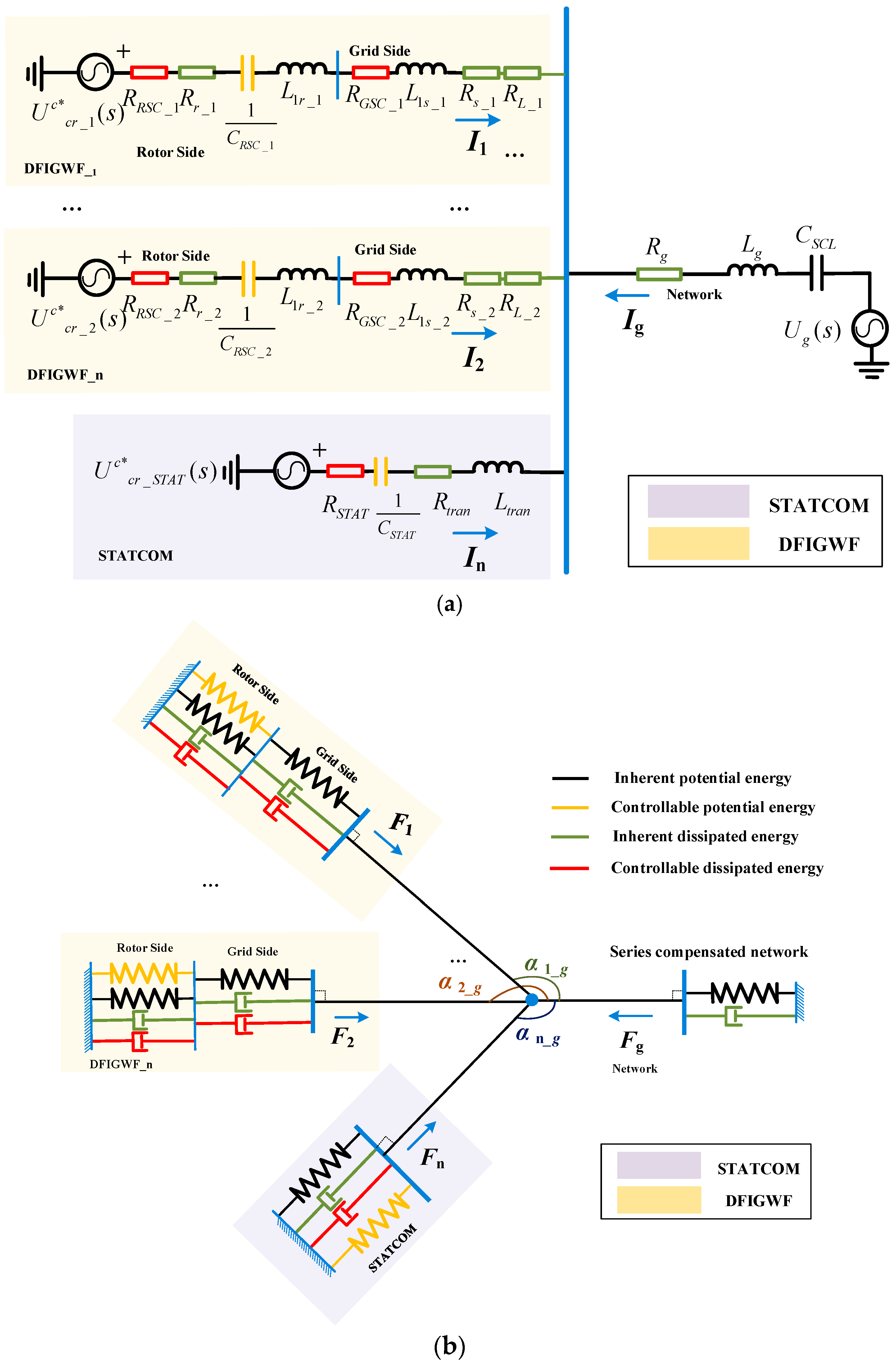
The test system in this paper is shown in Figure 2. Multiple DFIG-based wind farms (DFIGWF) and a shunt STATCOM are integrated in parallel into an infinite power source via a transformer and a series-compensated network. Existing works have revealed the interaction between the IBRs (i.e., DFIG-based wind farm or a shunt STATCOM) and the series-compensated network. This section uses the 2DOF-EEES to evaluate the interactions of the wind farms with the network and the IBRs.
The corresponding equivalent circuits of the test system can be obtained from Figure 3a [26]. Then, based on the analogy relationships in Section 2, the equivalent circuits can be analogized as 2DOF-EEES (shown in Figure 3b). In Figure 3, the potential energy and dissipated energy generated by the equivalent reactance and resistance in Figure 3a correspond to the energy generated by the spring and damper in Figure 3b, respectively. In addition, according to whether this energy is related to the converter controllers, the energy can be further defined as controllable energy and inherent energy, respectively. Specifically, the controllable energy originates from the dynamic responses of control systems within inverter-based resources, such as the active damping, current control, or voltage control loops of DFIGs and STATCOMs. This energy reflects how control parameters influence system stability and oscillation suppression. In contrast, the inherent energy is determined by the passive components of the network, including line impedance, transformer reactance, and machine parameters, which characterize the natural oscillatory behavior of the electrical system without control intervention. By distinguishing controllable and inherent energy, the proposed 2DOF-EEES can reveal how control strategies interact with the system’s physical characteristics to influence overall oscillatory stability.
Then, the explicit expressions of the damping and stiffness coefficients DDFIGWF_i, kDFIGWF_i, DSTATCOM and kSTATCOM for the DFIG-based wind farm have been derived [26], which are given in Equation (3). The derivation process of kDFIGWF_i and DSTATCOM is similar to the damping coefficient and stiffness coefficient of wind farms and will not be repeated here.
ω m D D F I G W F _ i = R D F I G W F _ i ( s ) = R r _ i + R w R S C _ i ( s )   + R s _ i + R L _ i + R w G S C _ i ( s ) ω m D S T A T C O M = R S T A T C O M ( s ) = R S T A T ( s ) k D F I G W F _ i = X D F I G W F _ i ( s ) = s L 1 r _ i + s L 1 s _ i s L L _ i + 1 s k i 4   + ( L m + L 1 s _ i ) s ( L m + L 1 s _ i ) k i 2 + ( k p 2 k i 1 + k i 2 k p 1 ) E s L m k S T A T C O M = X S T A T C O M ( s ) = s L S T A T ( s )
where Rr_i, Rs_i, and RL_i are the resistances of the rotor winding, stator winding, and transmission line of the ith DFIG-based wind farm, respectively. RwRSC_i and RwGSC_i are the equivalent resistances of the rotor-side converter (RSC) and grid-side converter (GSC) controllers of the ith DFIG-based wind farm. L1r_i, L1s_i, and LL_i represent the inductances of the rotor winding, stator winding, and transmission line of the ith DFIG-based wind farm, respectively. Lm is the magnetizing inductance. Es is the amplitude of stator voltage. kp1, ki1, kp2, and ki2 are the proportional and integral gains for the inner and outer control loops of the RSC controller. kp4 and ki4 are the proportional and integral gains for the inner control loop of the GSC controller. RSTAT and LSTAT are the equivalent resistance and inductance of the STATCOM.
Denote
R w R S C _ i ( s ) = k p 2 k p 1 + k i 2 k i 1 s 2 E s L m L m + L 1 s _ i + k p 2 C w R S C _ i = ( L m + L 1 s _ i ) ( L m + L 1 s _ i ) k i 2 + ( k p 2 k i 1 + k i 2 k p 1 ) E s L m R w G S C _ i ( s ) = k p 4 C w G S C _ i = 1 k i 4 R S T A T ( s ) = Re ( Z S T A T _ a v e ) L S T A T ( s ) = Im ( Z S T A T _ a v e )
where CwRSC_i and CwGSC_i are the equivalent capacitors of the RSC and GSC controllers of the ith DFIG-based wind farm.
Substituting Equation (3) into Equations (1) and (2), the common-mode energy Wh and differential-mode energy Wv of the test system can be derived as follows:
W h = W d _ WF _ NW + W p _ WF _ NW   i = 1 n cos 2 ( π α i _ n ) ω m D i Δ l i 2 d Δ θ e g   + i = 1 n cos 2 ( π α i _ n ) 1 2 k i Δ l i 2 l 0 l W v = W d _ WF _ WF + W p _ WF _ WF   i = 1 n sin 2 ( π α i _ n ) ω m D i Δ l i 2 d Δ θ e g   + i = 1 n sin 2 ( π α i _ n ) 1 2 k i Δ l i 2 l 0 l
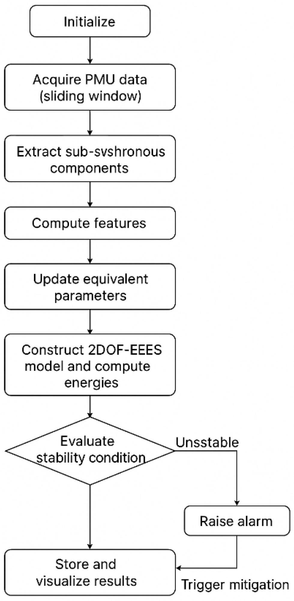
where Wd_WF_NW and Wp_WF_NW are the common-mode dissipated and potential energy, reflecting the total energy exchange and dissipation between the wind farms and the network. Wd_WF_ and Wp_WF_ are the differential-mode dissipated and potential energy, reflecting the total energy exchange and dissipation among the IBRs. αi_n and Δli correspond to the component current phase angle deviation βi_n and amplitude ΔIi, respectively. βi_n and ΔIi can be obtained by measuring the output current of each wind farm through a phasor measurement unit (PMU) and then decoupled by the discrete Fourier transform (DFT). Finally, based on the parameters and measured data of the test system, the interactions in the test system can be evaluated by Equation (4). An algorithm flowchart is shown in Figure 4 to demonstrate the feasibility of real-time evaluation for 2DOF-EEES. In practice, the interaction estimation process based on Equation (4) proceeds as follows: First, the phasor measurement units (PMUs) record the output current and voltage of each inverter branch at the common bus. These signals are processed using the discrete Fourier transform (DFT) to extract the amplitude ΔIi and phase angle βi_n of the sub-synchronous components. Second, these measured quantities, together with system parameters such as equivalent resistance (R), reactance (X), and the derived damping and stiffness coefficients (D and k), are substituted into Equation (4) to compute the common-mode energy (Wh) and differential-mode energy (Wv). The signs and magnitudes of the dissipated and potential energy terms (Wd and Wp) then indicate the degree of coupling and damping between different branches. Specifically, a negative dissipated work (Wd < 0) and a near-zero potential energy (Wp ≈ 0) imply that strong oscillatory interaction exists either among inverters or between the inverter cluster and the grid. This procedure enables real-time evaluation of the system’s dynamic interactions using both measurement data and known parameters.
As for the generality, the 2DOF-EEES method provides moderate-to-high generality by combining its two degrees of the dynamic models and PMU measurements, making it adaptable to multi-generator systems. As for the complexity, 2DOF-EEES requires an equivalent dynamic model and real-time measurement data but is less computationally heavy than eigenvalue-based analysis approaches. As for the real-time applicability, 2DOF-EEES can achieve high real-time applicability by dynamically updating operating parameters and integrating measurement information for online stability evaluation.

4. Case Study and Result Analysis

Simulation is performed based on the test system given in Figure 5. The control and network parameters of the test system can be found in [25], which are also given in Table 2. Two equivalent DFIG-based wind farms and a shunt STATCOM are directly integrated into the common bus. The number of online wind turbines in the two wind farms is 23 [called wind farm 1, WF1] and 77 [called wind farm 2, WF2], respectively. Each wind farm is interfaced via RSC/GSCs and connected to a 220 kV substation and integrated into a 500 kV infinite voltage source through a 500 kV series-compensated transmission line. To verify the effectiveness of the proposed 2DOF-EEES, two operating conditions have been conducted: the first one is to set up two wind farms with different resistance values of the transmission line connected to the common bus, and the second one is to set up different control parameters of the STATCOM.
Remark: There are four steps to evaluate the stability of the oscillatory system in the real world by the 2DOF-EEES, as shown in Figure 5.
Step 1: Measure and calculate the sub-synchronous oscillatory information (including ΔIi, Δθeg, ωe, and βi_g) by PMU at the terminal bus of the wind farm and shunt devices and DFT.
Step 2: Construct the 2DOF-EEES based on the equivalent frequency-scan or analytical model and the sub-synchronous oscillatory information.
Step 3: Calculate the common-mode energy and the differential-mode energy of the 2DOF-EEES in real time.
Step 4: Evaluate the risk of the oscillation by the energy-based stability criteria.
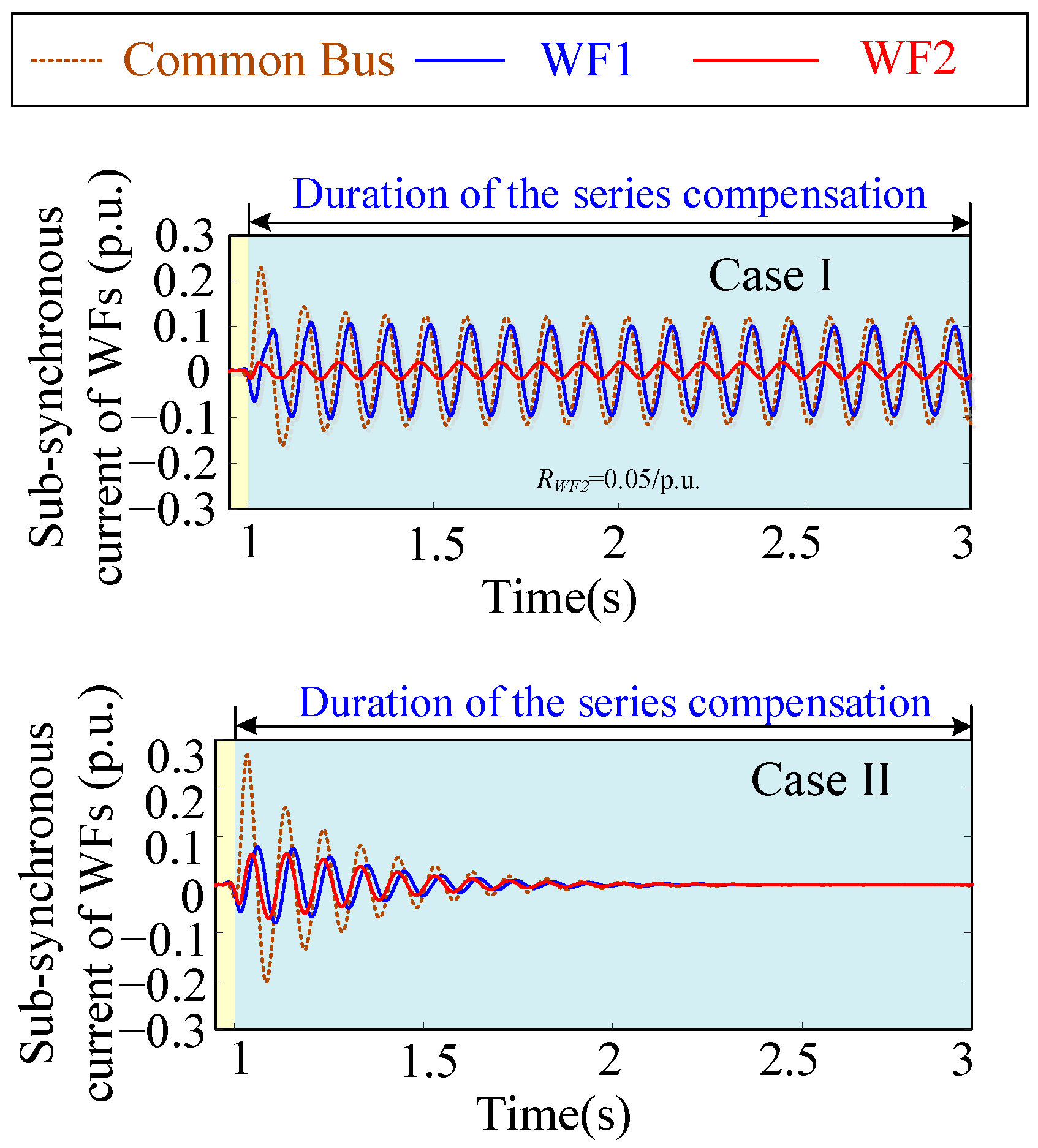
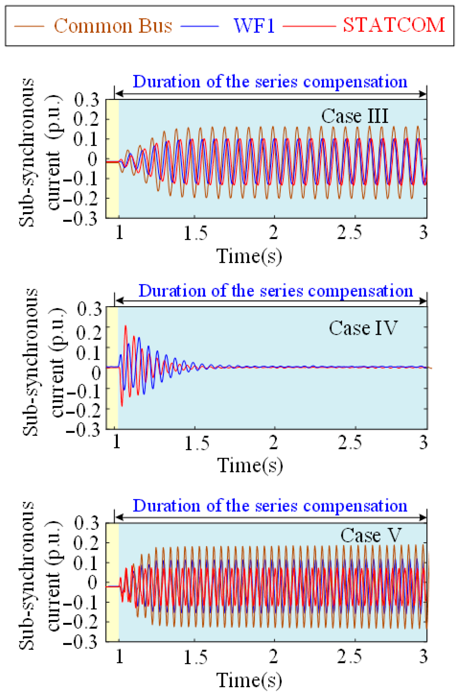
As for the first operating condition, the STATCOM is bypassed. WF2 is connected to the common bus through a transmission line with a resistance of 0.05 p.u. and 0.01 p.u. (called Case I and Case II), respectively, and WF1 is directly connected to the common bus. Based on the impedance analysis approach [9], the equivalent impedances of the test system (shown in Figure 5) are calculated in Table 3. It can be seen from Table 3 that when the resistance of the transmission line connected to WF2 RWF2 decreases from 0.05 p.u. to 0.01 p.u., the resonant frequency changes from 9.5 Hz to 10.3 Hz and the equivalent resistance varies from −0.0087 to −0.0093, indicating that the damping of the oscillatory system is decreased. Thus, the oscillation of the test system will aggravate from the view of frequency-domain impedance analysis. Simulation is also conducted under the same operating condition; the results (given in Figure 6) show that the oscillation curve of the sub-synchronous current of the system changes from divergence to convergence, indicating that the damping of the oscillatory system is changed from negative to positive, which is inconsistent with the conclusion drawn from the perspective of frequency-domain impedance analysis.
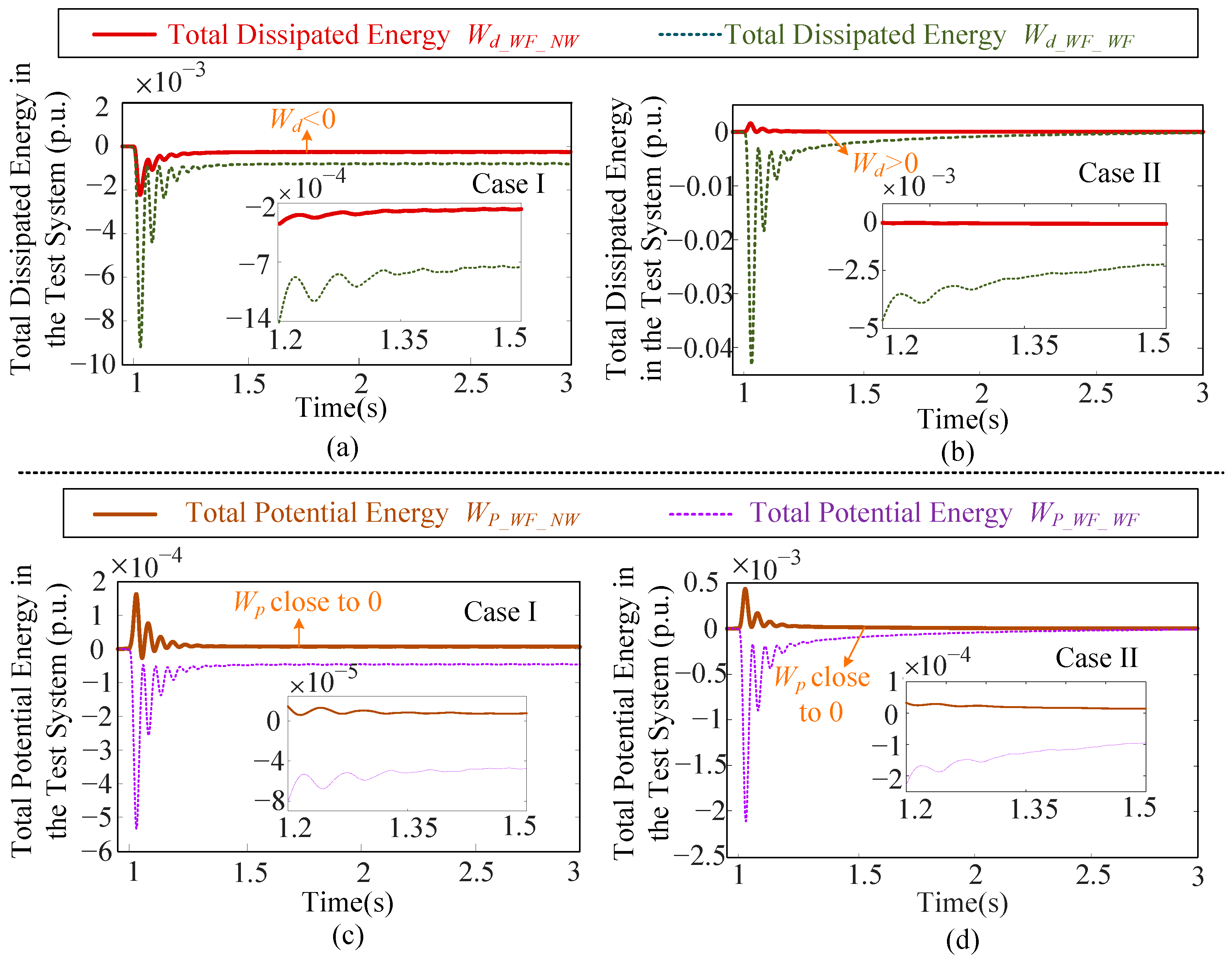
Then, by measuring the sub-synchronous variables (i.e., ΔI, Δθ, ωe, αi_g) at the terminal bus of each branch (extracting from the sub-synchronous current given in Figure 6) and then analogizing the test system (shown in Figure 5) into its equivalent 2DOF-EEES, the common-mode dissipated and potential energy (i.e., Wd_WF_NW and Wp_WF_NW) and the differential-mode dissipated and potential energy (i.e., Wd_WF_WF and Wp_WF_WF) of the 2DOF-EEES are calculated based on Equation (4). The results are shown in Figure 7.
As shown in Figure 7a,c, when the resistance of the transmission line for the WF2 is 0.05 p.u., the Wd_WF_NW is smaller than zero and the Wp_WF_NW is close to zero, which satisfies the criteria in Section 2, indicating that the divergent oscillation occurs between the wind farm and the network in the test system. In contrast, when the resistance of the transmission line for the WF2 is 0.01 p.u., as shown in Figure 7b,d, the Wd_WF_NW is larger than zero and the Wp_WF_NW is close to zero, which does not satisfy the criteria in Section 2, indicating that the oscillation converges between the wind farm and the network in the test system.
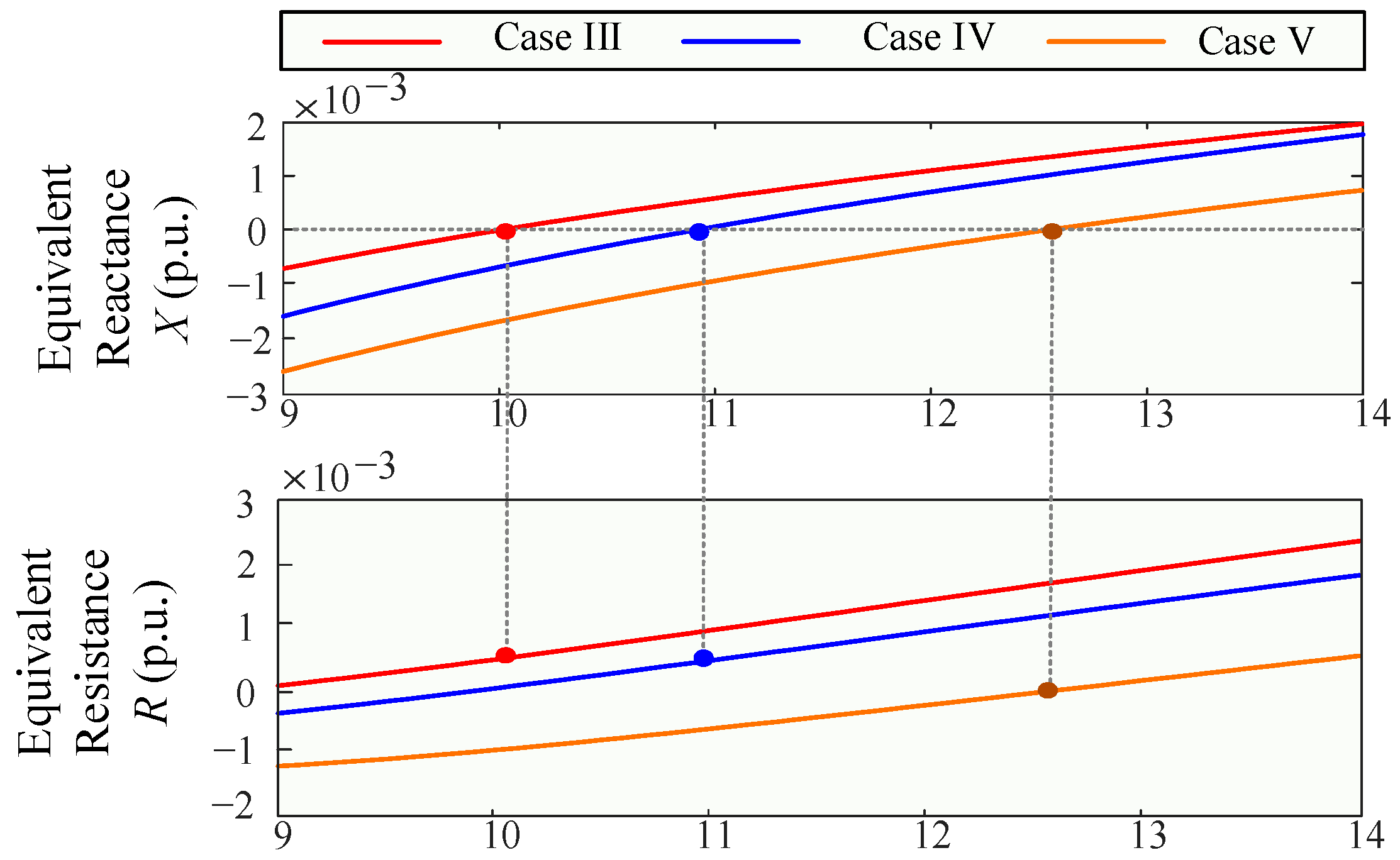
As for the second operating condition, the WF1 is bypassed. The STATCOM is directly connected to the common bus. Based on the impedance analysis approach, the equivalent impedances of the test system (shown in Figure 5) are calculated in Figure 8. It can be seen from Figure 8 that when the inner current control parameter of STATCOM changes from 2 to 0.1, the equivalent resistance varies from negative to positive, indicating that the damping of the oscillatory system is increased. The oscillation curve should change from divergence to convergence. However, the simulation results given in Figure 9 illustrate that as the parameters change, the oscillation first diverges, then converges, and finally diverges, rather than exhibiting a single trend of change. In contrast, the results obtained by the 2DOF-EEES given in Figure 10 are consistent with the simulation results since it considers both the common-mode energy and differential-mode energy.
It should be mentioned that the existence of the differential-mode energy will affect the common-mode energy through the equivalent elastic structure in the 2DOF-EEES, thus affecting the interaction between the wind farm and the network. However, from the view of the impedance analysis, such characteristics will not be reflected in the impedance network, which may bring inaccurate results in evaluating the risk of SSCI. The results in Figure 7 and Figure 10 demonstrate that variations in differential-mode energy alter the evolution of common-mode energy during transient events. When the differential-mode dissipated energy becomes negative, indicating strong inter-inverter coupling, the common-mode damping decreases, leading to system-wide oscillations. Conversely, when the differential-mode energy is well-damped, it stabilizes the common-mode behavior. This dynamic linkage highlights that the internal interactions among parallel inverters can either stabilize or destabilize the overall system, depending on their phase alignment and control coordination.
In addition, the sensitivity analysis results of certain parameters are given below. When the control parameters of the STATCOM and wind speeds are changed by ±20%, the variation range of the common-mode dissipated energy Wd and potential energy Wp at the sub-synchronous frequencies (ranging from 5 Hz to 45 Hz) can be calculated as shown in Table 4.
As shown in Table 4, the variation range of the common-mode dissipated energy resulting from a ±20% change in wind speed is larger than that caused by other parameters during the oscillation. This observation indicates that wind speed has a higher sensitivity to SSCI compared to the inner current control parameter kp4 of the STATCOM. Sensitivity analyses for the remaining parameters can be performed in a similar manner and are therefore not repeated here.

5. Conclusions

This paper proposes a two-degree-of-freedom elastic energy equivalent system (2DOF-EEES) to analyze the interactions in multi-inverter-based resource (IBR) heterogeneous systems. Compared with conventional impedance analysis, the 2DOF-EEES can simultaneously reveal and evaluate interactions between IBRs and the network and among different IBRs themselves. This is achieved by constructing an equivalent elastic structure with two degrees of freedom (i.e., the horizontal and vertical directions). By increasing the length of the collection line or increasing the current inner loop control parameters of STATCOM, the IBR can improve the system damping from the analysis of the frequency-domain impedance aggregation modeling approach. However, when considering the interaction between IBRs from the analysis of 2DOF-EEES, the damping of the system cannot be improved under the same operating conditions. The simulation results are consistent with the results obtained by 2DOF-EEES. Based on the proposed 2DOF-EEES, the sensitivity of parallel device parameters can be evaluated, and the safe range and adjustment direction of parameters can be determined, thereby forming a suppression strategy to deal with the interactions in the power systems integrated with heterogeneous IBRs.
Future studies should explore the oscillatory instability induced by the interaction of different types and operating conditions of IBRs based on the 2DOF-EEES. The proposed approach also has the potential to be applied in multi-region or HVDC systems. In addition, the 2DOF-EEES can only evaluate the energy flow at a certain frequency; the energy flow between different frequencies should be further studied, which may require a higher-dimensional EEES.

Author Contributions

Conceptualization, J.H.; methodology, J.H.; software, J.H.; validation, J.H., Y.Y. and L.S.; formal analysis, J.H. and Y.Y.; investigation, J.H., L.S., J.B., Y.Z. and X.D.; resources, X.Z., J.B. and X.D.; data curation, Y.Y., Y.W., H.D. and Z.S.; writing—original draft preparation, J.H.; writing—review and editing, Y.Y. and L.S.; visualization, J.H., H.D. and Y.Y.; supervision, X.Z. and X.D.; project administration, L.S. and X.D.; funding acquisition, X.Z. and X.D. All authors have read and agreed to the published version of the manuscript.

Funding

This research was funded by State Grid Corporation of China Project under Grant 5400-202318568A-3-2-ZN.

Data Availability Statement

The data presented in this study are available on request from the corresponding author.

Conflicts of Interest

Authors Xulin Zheng, Jingjing Bai, Yang Zheng, Yuanyuan Wang, Hao Ding and Zhixiong Su were employed by the company State Grid Jiangsu Electric Power Company Yancheng Power Supply Bureau. The remaining authors declare that the research was conducted in the absence of any commercial or financial relationships that could be construed as a potential conflict of interest.

Appendix A

Table A1. The variable definitions of this paper.
VariablesDefinition
βn_nThe current phase angle of the common branch, βn_n = 0.
βi_nThe current phase angle deviation between the common branch and ith RLC branch.
αi_nThe angle deviation for the ith spring–damper branch.
Wh, WvThe work performed in the direction of the common branch and in its vertical direction.
Wh_d, Wv_dThe dissipated energy of the 2DOF-EEES in the horizontal direction and vertical direction.
Wh_p, Wv_pThe potential energy of the 2DOF-EEES in the horizontal direction and vertical direction.
Fi, liThe force and deformation of the ith branch.
θegThe voltage phase deviation of the RLC branch
Ri, XiThe resistance and reactance of the ith series RLC branch.
Di, kiThe damping and stiffness coefficients of the ith equivalent spring–damper branch.
ωmThe angular frequency of mechanical system.
ωeThe angular frequency of series RLC circuit.
I0, IThe initial and real-time RMS value of the branch current.
DDFIGWF_i, kDFIGWF_iThe damping and stiffness coefficients of ith DFIG-based wind farm.
DSTATCOM, kSTATCOMThe damping and stiffness coefficients of the STATCOM.
Wd_WF_NW, Wp_WF_NWThe common-mode dissipated energy and potential energy between the wind farms and the network.
Wd_WF, Wp_WFThe differential-mode dissipated energy and potential energy among the IBRs.
IiThe output current of ith DFIG-based wind farm.
Rr_i, Rs_i, RL_iThe resistances of the rotor winding, stator winding, and transmission line of the ith DFIG-based wind farm.
L1r_i, L1s_i, LL_iThe inductances of the rotor winding, stator winding, and transmission line of the ith DFIG-based wind farm.
LmThe magnetizing inductance.
EsThe amplitude of stator voltage.
RwRSC_i, RwGSC_iThe equivalent resistances of the RSC and GSC of the ith DFIG-based wind farm.
CwRSC_i, CwGSC_iThe equivalent capacitor of the RSC and GSC controller of the ith DFIG-based wind farm.
RSTAT, LSTATThe equivalent resistance and inductance of the STATCOM.
kp1, ki1The proportional and integral gains of the outer loop in RSC controller.
kp2, ki2The proportional and integral gains of the inner loop in RSC controller.
kp3, ki3The proportional and integral gains of the Udc regulator in GSC controller.
kp4, ki4The proportional and integral gains of the current regulator.

References

  1. Salehi, F.; Matsuo, I.B.M.; Brahman, A.; Tabrizi, M.A.; Lee, W.-J. Sub-Synchronous Control Interaction Detection: A Real-Time Application. IEEE Trans. Power Deliv. 2020, 35, 106–116. [Google Scholar] [CrossRef]
  2. Wu, X.; Xu, S.; Feng, S.; Fan, L.; Gu, W. Time-varying Sub-synchronous Oscillation Mitigation Strategy for DFIG Wind Farms Based on Improved Adaptive Notch Filter. Proc. CSEE 2024, 44, 1836–18498. [Google Scholar]
  3. Shair, J.; Xie, X.; Wang, L.; Liu, W.; He, J.; Liu, H. Overview of emerging subsynchronous oscillations in practical wind power systems. Renew. Sust. Energ. Rev. 2019, 99, 159–168. [Google Scholar] [CrossRef]
  4. Virulkar, V.; Gotmare, G. Sub-synchronous resonance in series compensated wind farm: A review. Renew. Sustain. Energy Rev. 2016, 55, 1010–1029. [Google Scholar] [CrossRef]
  5. Bin, Z.; Feng, X.; Miao, Z.; Kong, X.; Li, P.; Shao, B. Frequency Characteristic Analysis of the VSC-HVDC DC Oscillating Power under AC Sub-Synchronous Disturbances. Electronics 2024, 13, 3445. [Google Scholar] [CrossRef]
  6. Chao, W.; Deng, C.; Huang, J.; Dai, L.; Min, Y.; Cheng, Y.; Wang, Y.; Liao, J. A Sub-Synchronous Oscillation Suppression Strategy Based on Active Disturbance Rejection Control for Renewable Energy Integration System via MMC-HVDC. Electronics 2023, 12, 2885. [Google Scholar] [CrossRef]
  7. Shair, J.; Xie, X.; Liu, W.; Li, X.; Li, Z. Modeling and stability analysis methods for investigating sub-synchronous control interaction in large-scale wind power systems. Renew. Sustain. Energy Rev. 2021, 135, 110420. [Google Scholar] [CrossRef]
  8. Liu, H.; Xie, X.; Gao, X.; Liu, H.; Li, Y. Stability analysis of SSR in multiple wind farms connected to series-compensated systems using impedance network model. IEEE Trans. Power Syst. 2018, 33, 3118–3128. [Google Scholar] [CrossRef]
  9. Miao, Z. Impedance-model-based SSR analysis for Type 3 wind generator and series-compensated network. IEEE Trans. Energy Convers. 2012, 27, 984–991. [Google Scholar] [CrossRef]
  10. Shao, B.; Zhao, S.; Gao, B.; Yang, Y.; Blaabjerg, F. Adequacy of the Single-Generator Equivalent Model for Stability Analysis in Wind Farms with VSC-HVDC Systems. IEEE Trans. Energy Convers. 2021, 36, 907–918. [Google Scholar] [CrossRef]
  11. Li, H.; Shair, J.; Zhang, J.; Xie, X. Investigation of sub-synchronous oscillation in a DFIG-based wind power plant connected to MTDC grid. IEEE Trans. Power Syst. 2023, 38, 3222–3231. [Google Scholar]
  12. Bostani, Y.; Jalilzadeh, S.; Mobayen, S.; Skruch, P.; Fekih, A.; Din, S. Damping sub-synchronous resonance in DFIG wind farms: An innovative controller utilizing wide-area measurement systems. Energy Rep. 2023, 10, 333–343. [Google Scholar] [CrossRef]
  13. Han, J.; Liu, C. Distributed Damping Evaluation for Series-Compensated DFIG-Based Wind Farms During the SSCI. In Proceedings of the 2023 IEEE Power & Energy Society General Meeting (PESGM), Orlando, FL, USA, 16–20 July 2023. [Google Scholar]
  14. Du, W.; Chen, X.; Wang, H. DFIG oscillation modes causing strong dynamic interactions to degrade the damping of power system low-frequency electromechanical oscillations. Electr. Power Compon. Syst. 2019, 47, 288–300. [Google Scholar] [CrossRef]
  15. Ebrahimzadeh, E.; Blaabjerg, F.; Wang, X.; Bak, C.L. Bus participation factor analysis for harmonic instability in power electronics-based power systems. IEEE Trans. Power Electron. 2018, 33, 10341–10351. [Google Scholar] [CrossRef]
  16. Wu, M.; Xie, L.; Cheng, L.; Sun, R. A Study on the impact of wind farm spatial distribution on power system sub-synchronous oscillations. IEEE Trans. Power Syst. 2016, 31, 2154–2162. [Google Scholar] [CrossRef]
  17. Fan, L.; Zhu, C.; Miao, Z.; Hu, M. Modal analysis of a DFIG-based wind farm interfaced with a series compensated network. IEEE Trans. Energy Convers. 2011, 26, 1010–1020. [Google Scholar] [CrossRef]
  18. Zhang, R.; Zhang, H.; Ye, J.; Wang, J.; Liu, Q.; Li, S. Eigen-Sensitivity-Based Sliding Mode Control for LFO Damping in DFIG-Integrated Power Systems. Energies 2023, 16, 4256. [Google Scholar] [CrossRef]
  19. Zha, S.; Liao, M.; Huang, Z.; Yang, Z.; Sun, J. Dynamic aggregation modeling of grid-connected inverters using Hamilton’s-action based coherent equivalence. IEEE Trans. Ind. Electron. 2019, 66, 6437–6448. [Google Scholar] [CrossRef]
  20. Liao, S.; Chen, Y.; Huang, M.; Fu, X.; Zha, X.; Wang, L.; Luo, A.; Guerrero, J.M. Clustering-Based Modeling and Interaction Analysis of Multiple Differently Parameterized Grid-Side Inverters in PMSG Wind Turbines. IEEE Trans. Energy Conver. 2021, 36, 3031–3043. [Google Scholar] [CrossRef]
  21. Liu, Y.; Guo, G.; Wang, X.; Wang, H.; Wang, L. Sub-Synchronous Oscillation Suppression Strategy Based on Impedance Modeling by Attaching Virtual Resistance Controllers for Doubly-Fed Induction Generator. Electronics 2022, 11, 2272. [Google Scholar] [CrossRef]
  22. Sun, D.-Y.; Qian, Z.-J.; Shen, W.-Q.; Zhou, K.; Jin, N.-Z.; Chen, Q.-G. Mechanism Analysis of Multiple Disturbance Factors and Study of Suppression Strategies of DFIG Grid-Side Converters Caused by Sub-Synchronous Oscillation. Electronics 2023, 12, 2293. [Google Scholar] [CrossRef]
  23. Ma, J.; Wang, L.; Cheng, P. An active damping control strategy for grid-tied Type-4 wind turbine generator based on energy feedback. IEEE Trans. Power Electron. 2022, 37, 5003–5020. [Google Scholar] [CrossRef]
  24. Ma, J.; Shen, Y.; Phadke, A.G. Stability assessment of DFIG susynchronous oscillation based on energy dissipation intensity analysis. IEEE Trans. Power Electron. 2020, 35, 8074–8087. [Google Scholar] [CrossRef]
  25. Liu, C.; Han, J. Evaluation of the Sub-Synchronous Control Interaction Based on the Elastic Energy Equivalent System. IEEE Trans. Power Syst. 2023, 38, 3897–3910. [Google Scholar] [CrossRef]
  26. Han, J.; Liu, C. Performance evaluation of the SSCI damping controller based on the elastic energy equivalent system. Appl. Energy 2023, 331, 120270. [Google Scholar] [CrossRef]
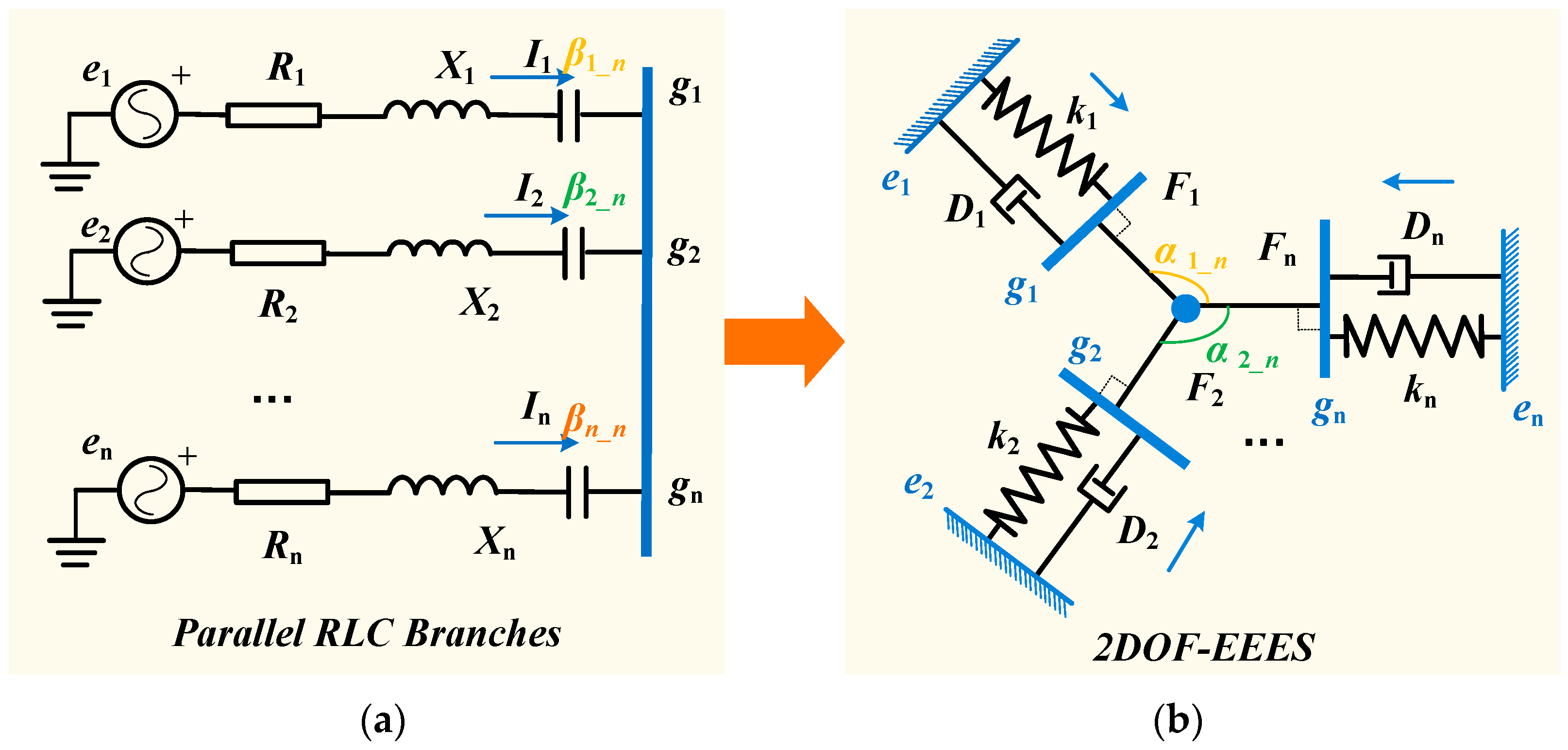
Figure 1. The analogy relationship between the parallel RLC branches and the 2DOF-EEES. (a) The structure of parallel RLC branches. (b) The structure of the 2DOF-EEES.
Electronics 14 04479 g001
Figure 2. The physical structure of the test system.
Electronics 14 04479 g002
Figure 3. The circuits of the test system. (a) The electrical equivalent circuit. (b) The 2DOF-EEES circuit.
Electronics 14 04479 g003
Figure 4. The algorithm flowchart of the real-time application of 2DOF-EEES.
Electronics 14 04479 g004
Figure 5. The power systems integrated with heterogeneous DFIG-based wind farms.
Electronics 14 04479 g005
Figure 6. Simulation results with different resistance values of the transmission line connected to the common bus.
Electronics 14 04479 g006
Figure 7. The common-mode energy and differential-mode energy of the test system with different resistance values of the transmission line connected to the common bus for the first operating condition. (a) Total dissipated energy of Case I. (b) Total dissipated energy of Case II. (c) Total potential energy of Case I. (d) Total potential energy of Case II.
Electronics 14 04479 g007
Figure 8. Equivalent impedances of the test system with different control parameters of the STATCOM connected to the common bus.
Electronics 14 04479 g008
Figure 9. Simulation results with different control parameters of the STATCOM connected to the common bus.
Electronics 14 04479 g009
Figure 10. The common-mode energy and differential-mode energy of the test system with different resistance values of the transmission line connected to the common bus for the second operating condition.
Electronics 14 04479 g010
Table 1. The mathematical comparison between the impedance models and the 2DOF-EEES.
Impedance Models2DOF-EEES
RωmD
X/ωek
Il
UF
βα
Table 2. The control and network parameters for simulation in case study.
VariablesDefinitionValue
PW1The capacity of the wind farm 1.46 MW
PW2The capacity of the wind farm 2.154 MW
UnThe rated voltage of wind farm.0.69 kV
fnThe synchronous frequency.50 Hz
UdcThe rated value of DC voltage between RSC and GSC.1.15 kV
CdcThe value of DC capacitor between RSC and GSC.10 mF
kp1, ki1The proportional and integral gains of the outer loop in RSC controller.0.5, 10
kp2, ki2The proportional and integral gains of the inner loop in RSC controller.0.6, 8
kp3, ki3The proportional and integral gains of the Udc regulator in GSC controller.8, 400
kp4, ki4The proportional and integral gains of the current regulator.0.83, 5
RsThe stator resistance.0.023 p.u.
RrThe rotor resistance.0.016 p.u.
L1sThe inductances of the rotor winding.0.18 p.u.
L1rThe inductances of the stator winding.0.16 p.u.
LmThe magnetizing inductance.2.9 p.u.
EsThe amplitude of stator voltage.1.0 p.u.
Table 3. Equivalent impedances of the test system with different resistance values of the transmission line connected to the common bus.
Resonant FrequencyEquivalent ImpedancesPhase Angle
Case I10.3 Hz−0.0093 p.u.182.5
Case II9.5 Hz−0.0087 p.u.181.6
Table 4. The variation range of the common-mode dissipated energy and potential energy.
Energy ClassificationParametersVariation Range
Common-mode dissipated energyWind speed Vw−0.002–0.001
Inner current control parameter of STATCOM kp4−0.0015–−0.0005
Common-mode potential energyWind speed Vw0.000005–0.00004
Inner current control parameter of STATCOM kp40.00001–0.00002
Disclaimer/Publisher’s Note: The statements, opinions and data contained in all publications are solely those of the individual author(s) and contributor(s) and not of MDPI and/or the editor(s). MDPI and/or the editor(s) disclaim responsibility for any injury to people or property resulting from any ideas, methods, instructions or products referred to in the content.