Abstract
In order to solve the problem of the IEEE 1588 (precise time protocol, PTP) path delay asymmetry caused by network congestion in data center time synchronization, this paper proposes a novel PTP time synchronization mechanism based on the original path return method and minimum delay packet screening (MDPS) algorithm. The original path return method utilizes the routing record and source station routing function of the IP protocol to enable the PTP packet to return along the original path, ensuring sufficient conditions for delay symmetry of the forth and back paths. The MDPS algorithm is proposed to select the packets on the same path whose delay is not affected by network congestion, thereby fundamentally eliminating the problem of delay asymmetry of forth and back paths in the case of network congestion. To verify the performance of the proposed mechanism, a simulation of the PTP packet queuing model and PTP time synchronization is conducted. The simulation results show that the uncongested packet can be obtained within 2.2 s. Moreover, the maximum absolute time deviation between the slave and master clocks is reduced by approximately 50 times, and the standard deviation of the time deviation is reduced by about 2 orders of magnitude.
1. Introduction
With the rapid growth in computing demand, the global information and communication industry is attaching great importance to the construction and development of data centers. However, the efficient operation of data centers cannot do without high-precision synchronization technology [1]. According to an analysis, high-precision time synchronization can enhance the computing efficiency of distributed computing and the reading–writing efficiency of distributed databases [2]. It can also improve the forwarding efficiency of data and reduce latency [3,4]. Moreover, it can also accurately calculate path latency and conduct forwarding path planning. Currently, the main data network synchronization technologies include NTP and PTP. Among them, PTP has been widely applied in industries such as communication, power, and finance due to its high accuracy and suitability for Ethernet networks [5,6,7]. Therefore, this paper mainly focuses on the application research of PTP in data center time synchronization.
The principle of PTP is to conduct timestamp interaction between the master and slave clocks based on a ping-pong mechanism, and the slave clock calculates the time deviation between the slave and master clocks according to the obtained timestamps [8]. However, PTP can accurately measure the time deviation between the slave and master clocks only based on the assumption that the forth and back path delays of the packet are symmetrical. However, in actual networks, this assumption is often not satisfied, which greatly limits the application of this protocol. In data center networks, most of the existing equipment does not support PTP; PTP packets are transmitted together with service packets in the network [9,10]. During peak business hours, network congestion may occur, which could cause asymmetric path delays for PTP packets and even route switching [11]. To enhance the availability of PTP in an Ethernet network, PTP has undergone continuous evolution, including the addition of boundary clock (BC)/transparent clock (TC) function and synchronous Ethernet (SyncE) to the protocol [12], among other changes. The BC function can realize asymmetric delay compensation per hop through network management, and the TC function can record the residence time of the packet in the network equipment it passes through. These two functions are part of PTP, so it is ineffective for network equipment that does not support PTP. The SyncE function makes the frequency deviation between the slave and master clocks closer, but time and frequency are independent, so it does not solve the problem of the asymmetric path delay caused by network congestion either.
There are many existing methods for solving the problem of asymmetric path delay, which can be divided into filtering methods, the per-hop delay compensation method [13,14], and the optical switching method [15]. The filtering methods are further classified into the delay ratio method [16], the minimum queuing forwarding delay estimation algorithm [17], the Kalman filtering method [18,19,20,21], and the weighted moving average filter method [22].
The main idea of the delay ratio filtering method is to calculate the ratio of the forth and back path delays of the PTP packets. Packets with delay ratios within [0.97, 1.03] are selected as valid packets. This method assumes that the mean value of the delay ratio is 1; that is, the expected values of forth and back path delays are equal. However, in the actual network, the expected values are not very likely to be equal. Therefore, this method does not solve the problem of asymmetric path delays of PTP packets.
The minimum queuing forwarding delay estimation method compares whether the received Sync packet time interval and the Delay_Req packet time interval are the same as the set time intervals. If they are the same, it is assumed that the related Sync and Delay_Req packets are not affected by network congestion. However, if all the packet sequences are subject to the same delay, then the packet intervals will also be the same as the set intervals. At this time, the delay of the packets has an absolute deviation, which will affect the PTP synchronization accuracy.
The Kalman filtering and weighted moving average methods are used for linear unbiased least mean square error estimation for linear time-varying systems. They make the optimal estimate of the PTP time deviation based on the statistical characteristics of the noise and the current measurement values. Both methods require the assumption that there exists a statistical distribution with an expected value of zero for the delay difference between the forth and back packet paths. Therefore, these methods cannot be applied to scenarios where there is inherent path delay asymmetry caused by network congestion or to scenarios where there is physical path delay asymmetry caused by route switching.
The per-hop delay compensation method based on packet-relaying gateways calculates the clock frequency ratio between the gateway and the sensor nodes by recording the time interval between timestamps, and it then compensates for the processing delay of the gateway based on this ratio. This method can properly address the cumulative synchronization error over multiple hops. However, if there is severe network congestion in routers, the timestamps received by routers may deviate due to packet queuing. At this time, the measurement results of the clock frequency ratio between adjacent network nodes will have a certain deviation, thereby affecting the compensation accuracy of the router processing delay.
The method of optical switching needs to assume that the congestion situations on the forth and back paths are the same. However, in actual data center networks, the congestion situations of the forth and back paths are different. In addition, this method requires optical switches to be installed on both PTP master and slave clocks. It demands hardware modification and additional costs. At the same time, switching the transmitting and receiving channels will also interrupt the service data, which is not allowed in the existing network. Therefore, this method also fails to solve the problem of asymmetric delay of PTP packets.
For the problem of PTP path delay asymmetry in data center networks, the existing methods have their advantages but also have some shortcomings, as shown in Table 1. Based on the above analysis, this paper proposes a PTP time synchronization mechanism based on the original path return method and the MDPS algorithm. The original path return method solves the problem of incongruent forth and back paths. It provides a prerequisite for ensuring the packet time delay symmetry of the forth and back paths. The MDPS algorithm is proposed to select the packets that are not affected by network congestion on the same path. This can ensure that the forth and back path delays of PTP packets are symmetrical. After that, we establish a network traffic model, derive the probability density function of packet delay, and calculate the time required to obtain the packet with no congestion. Finally, we verify the algorithm through simulation, calculate the PTP time synchronization deviation, and compare the synchronization accuracy before and after using the algorithm in this paper.

Table 1.
Characteristics of the existing methods for PTP path delay asymmetry.
2. Principle
The system diagram of time synchronization between the master and slave clocks is shown in Figure 1. The master and slave clocks establish PTP interaction through a router network. The master clock, slave clock, and routers support the original path return function. After the slave clock receives the PTP packets, the time data is processed using the MDPS algorithm. Finally, the slave clock is disciplined and synchronized to the master clock. The PTP interaction process between the master and slave clocks is as follows. First, the master clock sends a Sync packet to the slave clock carrying the timestamp of the time when the Sync packet leaves the master clock. The slave clock then records the timestamp upon receiving the Sync packet. If it is a two-step mode, the timestamp is carried by the Follow_Up packet to the slave clock. Subsequently, the slave clock sends a Delay_Req packet to the master clock and records the departure timestamp of the packet. The master clock records the arrival timestamp upon receiving the Delay_Req packet and sends the timestamp to the slave clock via the Delay_Resp packet. After the slave clock receives the Delay_Resp packet, it has the four timestamps , , , and . Then the time deviation between the slave and master clocks is . The original path return method and the MDPS algorithm are introduced in detail as follows.

Figure 1.
System diagram of time synchronization between master and slave clocks.
2.1. Original Path Return Method
The method utilizes the routing record and source station routing functions, which are also named the -R and -G options of the IP protocol [23]. The -R and -G options are inherent functions of the IP protocol. These options are located in the header field of the IP packet, occupying a total of 39 bytes. The first byte is named code. For the -R option, the value of the code is set to 7, and for the -G option, the value is set to 0x89. The 4th to the 39th bytes are the IP address field, which can accommodate nine IP addresses. When an IP packet arrives at a router, the router will read the header field of the packet to determine whether it is the -R or -G option. Then, through the software program, the corresponding operations on the IP field of the packet will be implemented. After that, the packet will be forwarded. Those functions are supported by most existing Ethernet equipment. The working principle of -R and -G options is as follows. When the master clock sends a Sync packet, the -R option is enabled in the packet. Each route that forwards the Sync packet will put its own IP address in the -R option field of the packet. When the Sync packet reaches the slave clock, the -G option is enabled in Delay_Req packet. The routing addresses recorded in the Sync packet are read and copied to the -G option field of the returned Delay_Req packet. Then the Delay_Req packet will be sent back to the master clock along the original path according to the IP addresses specified in the -G option. This ensures that the transmission paths of the Sync and Delay_Req packets are congruent. Both the -R and -G options are existing option functions of the IP protocol. Network equipment does not need to add additional functions. Only when the received IP list is copied to the returned IP packet at the receiver is additional processing required. Moreover, the time delay consumed during the IP-list-copying process is independent of the PTP mechanism, so it will not affect the PTP synchronization accuracy. Since the IP header has only limited space to store IP addresses and can only hold nine IP addresses, this option function is applicable to networks within nine hops, which is sufficient for data center networks.
2.2. MDPS Algorithm
The flowchart of the MDPS algorithm is shown in Figure 2. First, the timestamps , , , and of the PTP packets are obtained by the slave clock through PTP. The i represents the packet sequence number. Then the path delay of Sync and Delay_Req packets, and , is calculated. The minimum path delay of PTP packets, and , is calculated as well. and are regarded as the reference path delay. The path delay of the subsequent receiving PTP packets, and , needs to be compared with the reference path delay. If the packet path delay is less than the reference path delay, the reference path delay is updated. Otherwise, it is used to calculate the time deviation. If the time deviation between the packet path delay and reference path delay is less than the set time deviation threshold , it is taken to participate in calculating the average path delay and . Otherwise, it is filtered out as random noise, such as jitter. Finally, the time deviation of PTP synchronization, , is calculated, and the slave clock is disciplined using during the disciplining period T. While T is not up, the slave clock continues to collect PTP packets. When T is up, the MDPS algorithm is initialized. The setting of depends on the network delay noise and the accuracy of the equipment’s internal clock. Usually, is one order of magnitude smaller than the network delay noise to suppress the network delay noise, and one order of magnitude larger than the time deviation of the equipment’s internal clock to ensure the statistical characteristics of clock performance.
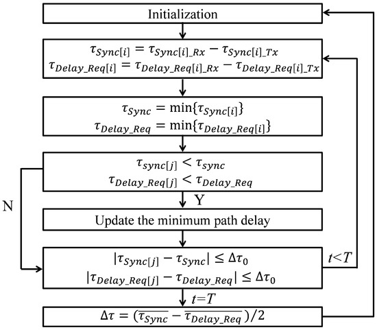
Figure 2.
Flowchart of MDPS algorithm.
Due to the congestion in the network, it takes a certain amount of time to obtain the uncongested packet. Then we calculate this measurement time to prove the usability of the algorithm. Most routers have a store-and-forward function. Under normal working conditions, the probability of cache overflow is very small, and it can be approximately considered that the cache capacity is unlimited. Therefore, the M/M/1 queuing model is introduced. It is assumed that the arriving data flow of the router follows a Poisson process with a parameter of , and the length of the data packet follows a negative exponential distribution. The average service rate is , and the service window is 1. The number of packets that stay in the switch increases with the arrival of the packets and decreases with the completion of packet processing. Thus, this system can be regarded as a process of birth and death. The state diagram is shown in Figure 3.

Figure 3.
Queuing process model of M/M/1.
Suppose the probability of having k packets in the switch is (), the probability of jumping from state k to state k + 1 is , the probability of jumping to state k − 1 is , the probability of jumping from state k + 1 to state k is , and the probability of jumping from state k − 1 to state k is . Thus, the differential Formula (1) is established.
When t approaches infinity, the system transits from the transient state to the steady state. It can be proved that when , the system has a stable distribution. Then it can be seen that
The process of protocol packets being transmitted in the network usually passes through multiple routers, so it is also necessary to analyze the situation of multiple routers. Considering the situation of circuitous data flow and repetitive flow near the router, the state is very complex, and the differential formula may be unsolvable. Therefore, we simplify the state transition diagram. According to the additivity of the Poisson process, if the data flow entering the router is a Poisson flow and the output remains a Poisson flow, then the data flow reaching the next-hop route is still a Poisson process, and the states between adjacent routers are independent of each other. Suppose represents the moment when the data stream leaves the i−1-th router, represents the moment when it leaves the i-th router, and then represents the time interval that the data stream takes from the i−1-th router to the i-th router. Then it can be proved that the arrival interval of the Poisson process is independent and identically distributed. It follows a negative exponential distribution as well. Then the total delay , where is an n-order Irish distribution, and the probability density function of can be obtained as
Then the probability distribution of is
Event and event are equivalent. represents the number of packets that have arrived during the time interval (0, t). Therefore,
It can be seen that is a Poisson process with parameters of , and the expectation of Formula (3) can be obtained as
This means that the average time required to pass through n routing systems is . It is n times the time taken by one route, so the model is self-consistent. In addition, when there are no packets in the system, the packets will not be congested. According to the principle of the birth-and-death process model and the additivity of the Poisson process, the probability of no packets in n router systems can also be obtained, as shown in Formula (7).
According to the classical probability theory, we can assume that detecting m times can obtain the uncongested packet with a certain probability, such as 95%, as shown in Formula (8). The value of m can be solved through interpolation fitting. Since the number of detections m can be converted into detection time, the detection time can also be obtained. In this way, it can be determined how much time is needed to obtain the uncongested PTP packets with 95% probability.
2.3. Semi-Attenuation Disciplining Algorithm
After obtaining the time deviation between the slave and master clocks, the semi-attenuation algorithm is used to discipline the slave clock. The principle of the semi-attenuation algorithm is as follows. Suppose the initial time deviation between the slave and master clocks is , and the disciplining period is T. During the disciplining period, the slave clock is in a free-run state, resulting in time deviation of . When the disciplining time is up, the time deviation between the slave and master clocks is measured through PTP as . The time adjustment quantity of the slave clock is set to half of the time deviation between the slave and master clocks, and negative feedback is applied to the time of the slave clock.
3. Simulation and Result Analysis
Based on the analysis in Section 2.2, a simulation is carried out. We suppose the average length of the network packet is 1000 bits, the transmission rate is Gigabits/s, the average arrival time of the packet is 2 µs, and the number of routing hops is 5. The internal clocks of the current network node equipment usually adopt high-stability crystal oscillators. Based on the typical performance parameters of high-stability crystal oscillators, it is assumed that the initial time deviation of the slave clock is 100 ns, the frequency deviation is , and the daily frequency drift rate is . At the same time, it is assumed that the time adjustment resolution of the equipment is 100 ps.
The period of the Sync and Delay_Req packets of PTP is set to 1/16 s, and the disciplining period T of the slave clock is set to 10 s. For comparison, we calculate the time deviation between the slave and master clocks, respectively, in the cases of using and not using the MDPS algorithm.
According to Section 2.2, it can be calculated that the average waiting time of the packet is 10 µs, and the probability of no congestion is 3.1%. This means that approximately 32 detections are required to obtain one uncongested packet. Since the Sync and Delay_Req packet rates of PTP are 16 Hz, it only takes about an average of 2 s. And if the detection lasts for more than 6 s, an uncongested packet can be obtained with 95% probability.
3.1. Time Synchronization Without Using the MDPS Algorithm
According to the analysis in Section 2.2, the delay of the PTP packet is the network packet delay . The average arrival rate , and the average service rate of the packet can be obtained based on the packet length and arrival time. According to the number of network hops and the probability density distribution function of the packet delay, we select the main range of the packet delay as [ s, s]. After simulation, the packet delay and delay distribution of the Sync and Delay_Req can be obtained as shown in Figure 4, Figure 5 and Figure 6.
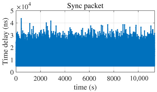
Figure 4.
Time delay of Sync packet.
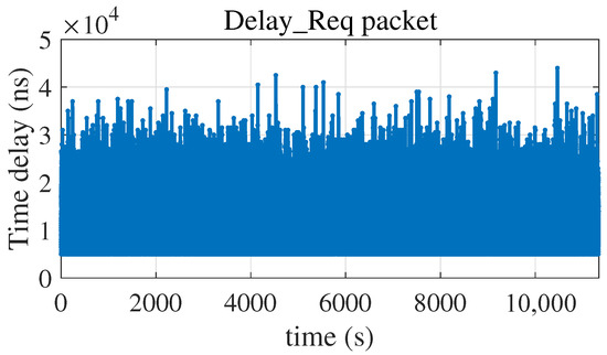
Figure 5.
Time delay of Delay_Req packet.
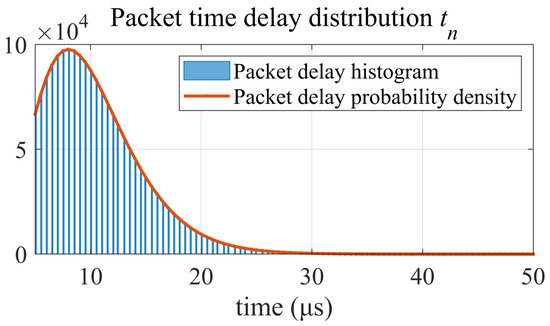
Figure 6.
Time delay distribution and probability density of Sync and Delay_Req.
It can be seen from Figure 6 that the packet delay distributions in Figure 4 and Figure 5 are consistent with the probability density of .
Without adopting the MDPS algorithm, the time deviation between the slave and master clocks is measured through PTP. The results show that the time deviation range of PTP is from −12.0 µs to 10.5 µs, with an average value of −42.5 ns and a standard deviation of 2.9 µs, as shown in Figure 7.
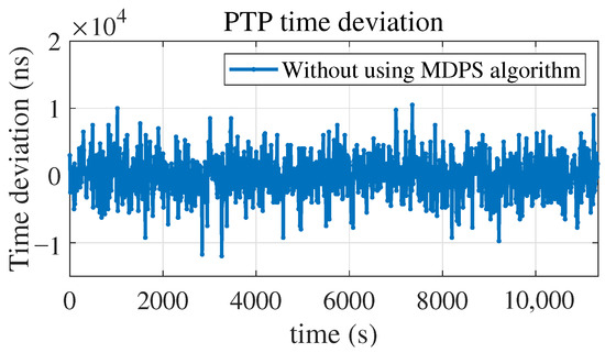
Figure 7.
PTP time deviation without using MDPS algorithm.
By disciplining the slave clock using the semi-attenuation algorithm, the time deviation between the slave and master clocks can be obtained, ranging from −6.7 µs to 5.3 µs, with an average value of −34.1 ns and a standard deviation of 1.7 µs, as shown in Figure 8.
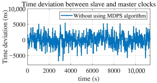
Figure 8.
Time deviation between slave and master clocks without using MDPS algorithm.
3.2. Time Synchronization Using the MDPS Algorithm
In Figure 7 and Figure 8, it can be seen that the standard deviation caused by the network noise is on the order of 2 µs. The time drift of the slave clock is 10 ns, caused by the internal clock within the disciplining period. According to the analysis in Section 2.2, it is assumed that the packet delay screening threshold = 200 ns. The minimum packet delays in Figure 4 and Figure 5 are screened in real time through the algorithm. The results show that the time delay of the Sync packet reaches the minimum value at 2.1875 s; that is, the Sync packet with the minimum delay is obtained at the 35th packet, and the Delay_Req packet reaches the minimum value at 0.375 s. That is, the Delay_Req packet with the minimum delay is obtained at the sixth packet, as shown in Figure 9 and Figure 10. The time deviation range of PTP is from −254.5 ns to 260.6 ns, with an average value of −0.7 ns and a standard deviation of 30.8 ns, as shown in Figure 11.
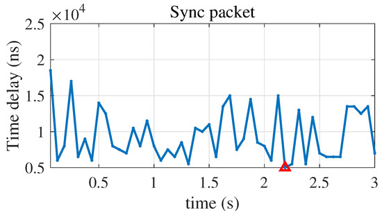
Figure 9.
Partial enlarged view of the time deviation of the Sync packet.
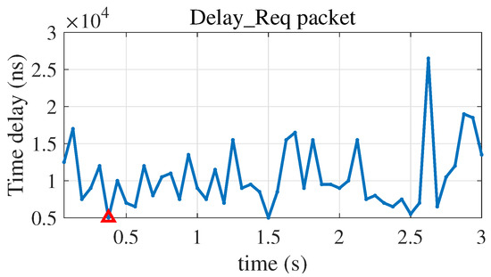
Figure 10.
Partial enlarged view of the time deviation of the Delay_Req packet.
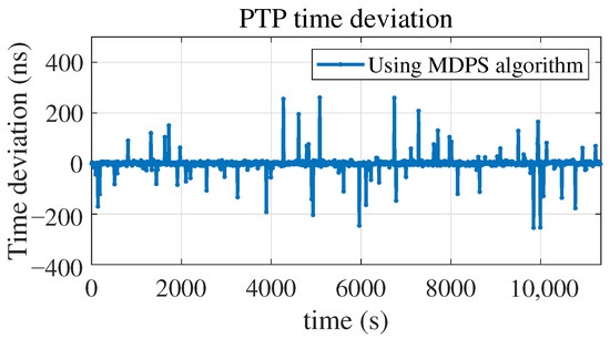
Figure 11.
PTP time deviation using MDPS algorithm.
By disciplining the slave clock using the semi-attenuation algorithm, the time deviation between the slave and master clocks can be obtained, ranging from −118.6 ns to 139.3 ns, with an average value of 9.3 ns and a standard deviation of 18.4 ns, as shown in Figure 12.
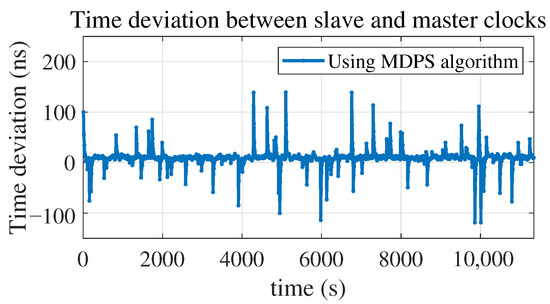
Figure 12.
Time deviation between slave and master clocks using MDPS algorithm.
3.3. Result Comparison and Analysis
It can be observed from Figure 9 and Figure 10 that after using the MDPS algorithm, the uncongested packet is obtained at the 35th PTP packet at 2.1875 s, which is marked with the red triangle. This is basically consistent with the 32nd packet at 2 s calculated in Section 3. At the same time, it can be observed from both Figure 8 and Figure 12 that after using the algorithm, the maximum absolute time deviation between the slave and master clocks decreases by approximately 50 times, from 6.7 µs to 139.3 ns, and the standard deviation of the time deviation decreases by approximately 2 orders of magnitude, from 1.7 µs to 18.4 ns.
4. Conclusions
This paper proposes a novel solution for the problem of PTP path delay asymmetry in data center time synchronization. The solution includes a method for the original route return of PTP packets and a screening algorithm for the packet with the minimum delay. The measurement time required to obtain the uncongested packet is calculated, and the modeling and simulation of the MDPS algorithm is carried out. The simulation results show that the MDPS algorithm can obtain the uncongested packet within approximately 2.2 s. Meanwhile, the maximum absolute time deviation between the slave and master clocks is reduced by approximately 50 times, and the standard deviation of the time deviation is reduced by approximately 2 orders of magnitude. Future research extending this work will focus on implementing the proposed method into a hardware prototype, which will be deployed in an actual network to verify the performance of our algorithm.
Author Contributions
Investigation, methodology, software, data curation, and writing—original draft preparation, X.M.; validation, resources, and funding acquisition, C.H.; conceptualization, supervision, and writing—review and editing, Y.Q. All authors have read and agreed to the published version of the manuscript.
Funding
This research was funded by the National Natural Science Foundation of China, grant number 42227802.
Data Availability Statement
Data are only available on request due to restrictions. The data presented in this study are available on request from the corresponding author.
Conflicts of Interest
The authors declare no conflicts of interest.
References
- Zhang, Q.; Zhang, C.; Wang, J.; Tang, X.; Shen, Z.; Wang, H. Nanosecond level time synchronization in datacenter network based on Telemetry architecture. J. Commun. 2021, 42, 117–129. [Google Scholar]
- Corbett, J.C.; Dean, J.; Epstein, M.; Fikes, A.; Frost, C.; Furman, J.J.; Ghemawat, S.; Gubarev, A.; Heiser, C.; Hochschild, P.; et al. Spanner: Google’s Globally Distributed Database. ACM Trans. Comput. Syst. 2013, 31, 8. [Google Scholar] [CrossRef]
- Ken, H. Fastpass: A centralized “zero-queue” datacenter network. In Proceedings of the 2014 ACM Conference on SIGCOMM, New York, NY, USA, 17–22 August 2014. [Google Scholar]
- Ding, R.; Dang, D.; Guo, Y.; Xue, X.; Guo, B.; Huang, S. Nanosecond Time Synchronization Technology for Time-slot Optical Switching Networks. Des. Tech. Posts Telecommun. 2024, 2, 22–26. [Google Scholar]
- Ken, H. An Application of IEEE 1588 to Industrial Automation. In Proceedings of the International IEEE Symposium on Precision Clock Synchronization for Measurement, Control and Communication, Ann Arbor, MI, USA, 22–26 September 2008. [Google Scholar]
- Ravi, S. Timing Recovery for IEEE 1588 Applications in Telecommunications. IEEE Trans. Instrum. Meas. 2009, 58, 1858–1868. [Google Scholar] [CrossRef]
- Jean-Charles, T.; Karl, W. Differences and Similarities between the Audio Video Bridges and Power System Profiles for IEEE 1588. In Proceedings of the International IEEE Symposium on Precision Clock Synchronization for Measurement, Control and Communication, Portsmouth, NH, USA, 27 September–1 October 2008. [Google Scholar]
- IEEE 1588-2008; IEEE Standard for a Precision Clock Synchronization Protocol for Networked Measurement and Control Systems. Technical Committee on Sensor Technology (TC-9): Geneva, Switzerland, 2008. Available online: https://ieeexplore.ieee.org/document/4579760 (accessed on 3 November 2025).
- Shuguang, Q.; Yu, Z.; Mengdi, W. Study and Application on Data Center Infrastructure Management System Based on Artificial Intelligence (AI) and Big Data Technology. In Proceedings of the IEEE 4th International Future Energy Electronics Conference, Singapore, 25–28 November 2019. [Google Scholar]
- Karanveer, A. AL-Driven Optimization of Cloud Data Centers: Enhancing Reliability and Cost Efficiency. In Proceedings of the 2025 International Conference on Data Science, Agents, and Artificial Intelligence, Chennai, India, 28–29 March 2025. [Google Scholar]
- Jiho, H.; Deog-Kyoon, J. Practical Considerations in the Design and Implementation of Time Synchronization Systems Using IEEE 1588. IEEE Commun. Mag. 2009, 47, 164–170. [Google Scholar] [CrossRef]
- IEEE 1588-2019; IEEE Standard for a Precision Clock Synchronization Protocol for Networked Measurement and Control Systems. Technical Committee on Sensor Technology (TC-9): Geneva, Switzerland, 2019. Available online: https://ieeexplore.ieee.org/document/9120376 (accessed on 3 November 2025).
- Huan, X.; Kim, K.S. Per-Hop Delay Compensation in Time Synchronization for Multi-Hop Wireless Sensor Networks Based on Packet-Relaying Gateways. IEEE Trans. Lett. 2020, 24, 2300–2304. [Google Scholar] [CrossRef]
- Huan, X.; Kim, K.S.; Lee, S.; Lim, E.G.; Marshall, A. Improving Multi-Hop Time Synchronization Performance in Wireless Sensor Networks Based on Packet-Relaying Gateways with Per-Hop Delay Compensation. IEEE Trans. Commun. 2021, 69, 6093–6105. [Google Scholar] [CrossRef]
- Xie, D. A method for automatic compensation of PTP asymmetry in the transmission network. China New Commun. 2014, 9, 79–80. [Google Scholar]
- Md, A. Delay Asymmetry Correction Model for IEEE 1588 Synchronization Protocol. Master’s Thesis, Carleton University, Ottawa, ON, Canada, 2013. [Google Scholar]
- Lei, C.; Tianlin, Z. Packet Delay Estimation Algorithm against FIFO Waiting for Asymmetric IEEE 1588 System. J. Comput. 2014, 9, 2075–2081. [Google Scholar] [CrossRef]
- Xing, K.; Yin, Y.; Huang, Y.; Gao, Y. Network time transfer accuracy improvement with Kalman filter method. Chin. J. Sci. Instrum. 2011, 32, 949–954. [Google Scholar]
- Lei, C.; Tianlin, Z. An Adaptive Filtering Algorithm with Packet Delay Variation for IEEE1588 Servo System. In Proceedings of the 11th IEEE International Conference on Electronic Measurement & Instruments, Harbin, China, 16–19 August 2013. [Google Scholar]
- Takahide, M.; Yukio, H.; Kosuke, N. A Packet Filtering Mechanism with a Packet Delay Distribution Estimation Function for IEEE 1588 Time Synchronization in a Congested Network. In Proceedings of the International IEEE Symposium on Precision Clock Synchronization for Measurement, Control and Communication, Munich, Germany, 12–16 September 2011. [Google Scholar]
- Kendall, C.; Nick, B.; Michael, B. Design Considerations for Software Only Implementations of the IEEE 1588 Precision Time Protocol. In Proceedings of the International IEEE Symposium on Precision Clock Synchronization for Measurement, Control and Communication, Bologna, Italy, January 2006; Available online: https://www.researchgate.net/publication/236213185 (accessed on 3 November 2025).
- Qian, C.; Xu, X.; Mei, J.; Yu, J.; Zheng, J.; Wang, Y.; Ji, W.; Zhang, M. Communication Path Queue-Induced Asymmetry Algorithm for Clock Synchronization On IEEE 1588. Power Syst. Technol. 2015, 39, 3622–3626. [Google Scholar]
- Richard, W.S. TCP/IP Illustrated; China Machine Press: Beijing, China, 2000; Volume 1, p. 61. [Google Scholar]
Disclaimer/Publisher’s Note: The statements, opinions and data contained in all publications are solely those of the individual author(s) and contributor(s) and not of MDPI and/or the editor(s). MDPI and/or the editor(s) disclaim responsibility for any injury to people or property resulting from any ideas, methods, instructions or products referred to in the content. |
© 2025 by the authors. Licensee MDPI, Basel, Switzerland. This article is an open access article distributed under the terms and conditions of the Creative Commons Attribution (CC BY) license (https://creativecommons.org/licenses/by/4.0/).