Abstract
In recent years, unmanned aerial vehicle (UAV) technology has been increasingly widely used in natural disaster rescue. To enable fast and accurate localization of rescue targets in disaster environments, this paper proposes a multi-level coordinate system transformation method for quadrotor UAVs based on monocular camera position compensation. First, the preprocessed image object is transformed from pixel coordinates to camera coordinates. Second, to address the issue that coupling errors between the camera and UAV coordinate systems degrade the accuracy of coordinate conversion and target positioning, a Static–Dynamic Compensation Model (SDCM) for UAV camera position error is established. This model leverages a UAV attitude-based compensation mechanism to enable accurate conversion of camera coordinates to UAV coordinates and north-east-down (NED) coordinates. Finally, according to the Earth model, a multi-level continuous conversion chain from the target coordinates to the Earth-centered–Earth-fixed (ECEF) coordinates and the world-geodetic-system 1984 (WGS84) coordinates is constructed. Extensive experimental results show that the accuracy of the overall positioning method is improved by approximately 23.8% after completing our camera position compensation, which effectively enhances the positioning performance under the basic method of coordinate transformation, and provides technical support for the rapid rescue in the post-disaster phase.
1. Introduction
Debris flow, typhoon, earthquake, mountain torrents, and other sudden natural disasters often cause severe damage to people’s lives and property [1,2,3,4,5]. In these cases, it is necessary to quickly carry out personnel search and rescue, material transportation, and other disaster relief operations [6], so as to maximize the lives and minimize the economic losses of people [7]. However, the post-disaster geographical environment is extremely harsh, which makes it difficult for rescuers to quickly obtain the target location for search and greatly affects the efficiency of rescue and relief. Understanding how to quickly and accurately obtain the location of disaster victims and other related rescue targets has become an important concern in the disaster relief process. In recent years, with a high degree of flexibility and autonomy, unmanned aerial vehicles (UAVs) have played an important role in many applications such as agriculture [8], surveying and mapping [9], meteorology [10], and transportation [11,12]. Among them, UAVs based on the four-rotor structure design have gradually become the mainstream application [13]. In a disaster rescue scenario, a quadrotor UAV can make full use of the advantages of airspace and avoid the terrain restrictions in disaster areas (Figure 1). Using a quadrotor UAV to carry out post-disaster rescue can greatly reduce the workload of search-and-rescue personnel, and improve the working efficiency [14]. In general, the small-quadrotor UAV can provide a wide range of target observation information for rescue workers through multiple observation angles of UAV pan tilt above the ground level in disaster areas, markedly boosting the efficiency of target detection and localization [15]. Therefore, in disaster relief operations, relying on quadrotor UAVs to treat and accurately locate search-and-rescue targets is a key issue to be studied.
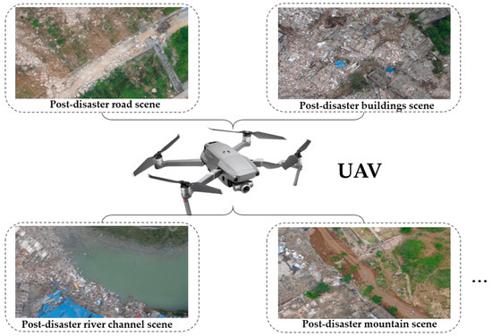
Figure 1.
Schematic diagram of post-disaster rescue mission scenes for UAV.
Many researchers have carried out corresponding studies using UAV equipment to locate ground targets. Some researchers have developed baseline methods for using drones for geolocation. For example, in [16], a visual geometry group (VGG) network was trained to extract high-dimensional features from drone template images and satellite reference images, enabling the localization of targets captured by drones in satellite images. However, real-world drone datasets are scarce, and feature robustness is insufficient in extreme scattering environments. In [17], scale-invariant feature transform (SIFT) feature matching and progressive homography transformation methods were used for post-disaster building damage localization and flood area estimation. However, this method relies too much on manual point selection, resulting in poor SIFT matching performance in featureless areas. In [18], a cognitive multi-stage search and geolocation (CMSG) cognitive multi-stage framework localization framework was proposed for urban stationary radiation source localization, but the algorithm has high complexity. In [19], the researchers proposed an improved processing method for digital surface model (DSM) generation for plant spike detection. In [20], the researchers used dual drones for multi-view geometric estimation of target height and iterative parameter regression calculation to locate indoor targets. These studies propose some baseline methods for drone geolocation that can be referenced.
At present, the main methods of UAV ground vision positioning can be divided into three categories: positioning based on auxiliary geographic information, positioning based on multi-angle pose relationship, and positioning based on target distance. The commonly used auxiliary geographic information method usually includes the digital elevation model (DEM) and DSM [21,22]. By expressing the solid ground and fixed surface model in the form of a grid, the supplementary elevation information is obtained, and the coordinates of the intersection of the point and the optical center line of the target on the image and model are solved. In [23], a method for three-dimensional (3D) geolocation of UAV images through database matching technology and ray DSM intersection was proposed. The root mean square error (RMSE) of the target was about 14 m. More methods combine the application of DSM data with the characteristics of images taken by UAVs. In [24], the human crowd image taken by a UAV camera was used to locate people in a large-scale outdoor environment by combining DSM data through the steps of back-projection and a Bayesian filtering fusion heat map. In [25], a method of locating the center target of an image taken by the airborne camera based on the aircraft navigation information was proposed. The target location was obtained by matching with the image features corrected by DSM, but its accuracy was low. In [26], the features of the captured image were matched with the features of an image under a DSM orthophoto to realize the direct mapping of video frame target and obtain the longitude and latitude height of the target. These auxiliary geographic-information-based positioning methods can improve accuracy but require complete regional geographic information data. This limits their applicability in actual post-disaster scenarios.
The multi-angle pose-relationship-based method measures targets from two or more directions, then solves for unique target coordinates using observation point coordinates and lines of sight between observation points and targets. While theoretically feasible, its practical application is often affected by various errors, leading to large positioning deviations. The common operation is to filter on the basis of multiple measurements. For example, the Kalman filtering method [27] or the Levenberg–Marquardt [28] method can be used to filter the UAV and target information collected by multiple measurements. However, for UAVs equipped with monocular cameras, the application of this principle method is very limited, and it is difficult to locate ground targets quickly. Therefore, the relevant researchers make up for the lack of a limited perspective by increasing the number of UAVs and use the state of each UAV to determine the intersection of multiple line-of-sight directions to confirm the target position. In [29], a geometric intersection model was designed in which two UAV optoelectronic platforms were used for target cross-positioning, and the adaptive Kalman filter model was used to estimate the optimal value. However, in the actual scene, multi-UAV target localization relies heavily on timestamp synchronization, requires stable communication conditions, and multi-UAV information fusion easily introduces additional errors. This makes it less convenient than the rapid maneuverability of a single UAV.
The key problem of localization is to obtain the target distance. If the depth information of the target can be obtained, the target position can be solved directly and accurately, which is also a kind of method commonly used in UAV target localization practice. In [30], a pseudo-stereo vision method was used to estimate the distance difference between the target and the UAV and then calculate the target location. In order to obtain more accurate distance estimation, further research used the statistical estimation method of multiple measurements to estimate the target position. In [31], the improved Monte Carlo method was used to optimize the error of multiple distance measurement results to improve accuracy. In [32], the method of regression analysis was used to estimate the azimuth deviation at the same time as positioning to improve the estimation accuracy. In [33], the target was reimaged with the aid of the roughly calculated position, and the reprojection error was weighted, filtered, optimized, and iteratively converged until it converged to the optimal value. In order to achieve the effect of rapid positioning, reference [34] established a triangle relationship based on the basic UAV altitude and camera angle information to estimate the target distance by implementing the image target center tracking method. This approach aligns with the requirements for rapidity in single-UAV search operations during disaster rescue. Accordingly, our method is optimized based on this framework: specifically, we incorporate the strategy of establishing a triangular relationship between the target and the UAV to supplement target distance information while explicitly constructing and refining the transformation relationships among multiple coordinate systems of the UAV. Meanwhile, with a specific focus on the deviation between the position of the Pan–Tilt–Zoom (PTZ) camera and the fuselage of a small quadrotor UAV, a correction model is established to refine the transformation relationships. In addition, the method of using monocular drones for geographic positioning has also undergone relevant research. For example, in [35], researchers used a monocular camera of a single drone to achieve ground target positioning by matching corresponding points and transforming mobile target positioning. In [36], researchers fused laser data to simulate binocular measurement on the basis of a monocular camera to achieve positioning. In [37], a combination of a monocular camera and an Inertial Measurement Unit (IMU) was used to achieve tightly coupled visual inertial estimation, with monocular vision running through the entire positioning process. These studies have demonstrated the feasibility and effectiveness of using monocular drones for geographic positioning, providing ideas for the proposal of our single drone combined with a visual processing geographic positioning method.
In this paper, a multi-level coordinate system transformation method for quadrotor UAVs based on monocular camera position compensation is proposed to realize the positioning of ground targets. First, the image target position obtained by the target recognition algorithm is transformed from the two-dimensional (2D) pixel coordinates to the three-dimensional camera coordinates. Second, to address the issue that positional offset errors between the camera and quadrotor UAV coordinate systems degrade coordinate conversion and positioning accuracy, a Static–Dynamic Compensation Model (SDCM) is established. Leveraging a compensation mechanism based on the quadrotor’s attitude angles, SDCM enables accurate conversion of camera coordinates to the UAV coordinates and north-east-down (NED) coordinates. Finally, a multi-level continuous transformation chain of target coordinates from NED coordinates to Earth-centered–Earth-fixed (ECEF) coordinates and world-geodetic-system 1984 (WGS84) coordinates is constructed based on the relationship between the three-dimensional mathematical model of the Earth and geodetic coordinate systems. Finally, the longitude and latitude coordinates of the image target are calculated.
The main contributions of this paper are summarized as follows:
- We propose an integrated method for UAV-based target recognition and positioning. This method synergistically combines a target recognition algorithm with a multi-level coordinate system transformation. By incorporating the quadrotor UAV’s flight attitude angles, pan–tilt angles, and other relevant parameters, it enables the calculation of the precise longitude and latitude coordinates of a target identified from captured images. The significance of this contribution lies in providing a complete and operational framework that bridges the gap between image-based target detection and the delivery of actionable, real-world geographic coordinates.
- We establish a Static–Dynamic Compensation Model (SDCM) based on a UAV attitude compensation mechanism. This model is designed to correct positional errors arising from the misalignment between the camera coordinate system and the UAV body coordinate system. The significance of this contribution is that it directly addresses a key source of inaccuracy in UAV positioning, thereby significantly enhancing the coordinate mapping precision and improving the overall target positioning performance of the proposed method.
- We design a multi-dimensional block iterative extended Kalman particle filter, BolckIKEF, to mitigate the impact of near-ground wind speed and other environmental factors on the six-dimensional attitude angles of the UAV and PTZ camera. The significance of this contribution lies in its direct enhancement of the system’s robustness. By effectively filtering the critical but noisy attitude and PTZ angle inputs, it significantly improves the reliability and final positioning accuracy of the overall system in dynamic flight conditions.
In the following sections, the multi-level coordinate transformation algorithm and the SDCM for camera position are elaborated in detail in Section 2. The experiment and analyses of the results of our proposed method are explained in Section 3. Further discussions of the design system are given in Section 4. Finally, the full text is summarized in Section 5.
2. Key Methods
2.1. Proposed Computational Flow Chart
Figure 2 presents the framework and calculation flow chart of our algorithm. After the quadrotor UAV flies over the target search-and-rescue area to capture target images, the UAV camera processing system first converts the 2D pixel coordinates (u, v) of the captured target to 3D camera coordinates (xc, yc, zc), using the focal length f and intrinsic parameters K of the UAV-mounted camera. Second, according to the three-dimensional coordinates of the target calculated in the previous step, the target coordinates are further calculated by using our proposed SDCM. After the camera coordinates are converted to UAV coordinates, the UAV coordinates are converted to NED coordinates, so that the target is converted to the coordinates under the UAV body system (xNED, yNED, zNED). Finally, with the assistance of the UAV’s latitude and longitude information (φd, λd, hd), a three-dimensional mathematical model of the Earth and a relationship with the geodetic coordinate system are constructed. Through the operation of converting NED coordinates to geocentric coordinates and converting from geocentric coordinates to WGS84 coordinates, the latitude and longitude coordinates (φ, λ, h) of the image target can be solved. Our proposed SDCM for small quadrotor UAVs effectively corrects errors in coordinate system transformations and significantly improves the computational accuracy of the overall positioning algorithm.
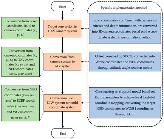
Figure 2.
The calculation flow chart of the designed ground target positioning method.
2.2. Target Conversion in UAV Camera System
By using the single-shot multibox detector (SSD) [38], the you only look once (YOLO) method [39], and other deep learning target recognition algorithms, the target can be accurately located from an image, and the accurate pixel coordinate information of the target can be obtained. Figure 3a shows the coordination relationship between the pixel coordinate system and the camera coordinate system in detail. The pixel coordinates of the target point are (u, v). The conversion from pixel coordinates to 3D camera coordinates needs to be derived based on camera imaging principle. A key operation is to add a dimension to the pixel coordinates. When calculating, we can add dimension “1” to the end of the pixel coordinates to convert them into homogeneous coordinates (u, v, 1) matching the 3D space. Another key challenge in converting 2D pixel coordinates to 3D camera coordinates is supplementing the missing depth information zc of the target point during projection. Monocular cameras cannot acquire this information due to their structural limitations. In order to solve this problem, according to the schematic model in Figure 3b, the triangular relationship among the UAV, the ground, and the target is established by using the UAV flight altitude H and the camera pitch angle θ, and the distance l between the target pixel and the image center is estimated according to the camera focal length information, and the oblique distance between the UAV and the target is quickly estimated to obtain the predicted distance depth information. The depth information zc of the target point in the camera coordinate system provides key depth parameter support for the subsequent conversion from pixel coordinates to 3D camera coordinates. By combining the focal length f and internal parameter K of the camera mounted on the UAV, the calculation formula for converting 2D pixel coordinates to 3D camera coordinates is given in Equation (1).
where the symbols fx and fy represent the focal length of the PTZ camera in the Xc- and Yc-axis directions of the camera coordinate system (consistent with the coordinate orientation in Figure 3a), respectively, with the unit of “pixel”. These two parameters reflect the scaling ratio of the camera for mapping physical spatial distances to image pixel distances, which is a core factor determining the accuracy of the “2D pixel → 3D camera coordinate” conversion in Formula (1). The symbols u0 and v0, respectively, represent the x-axis and y-axis coordinates of the image center. They, respectively, denote the pixel coordinates of the image center in the u-axis (horizontal right) and v-axis (vertical down) directions of the pixel coordinate system (i.e., the intersection coordinates of the camera optical axis Zc-axis in Figure 3a) and the pixel plane), which are used to eliminate the mapping deviation caused by the offset between the pixel coordinate origin (image upper-left corner) and the camera optical axis. These intrinsic parameters, encapsulated in the camera matrix K obtained from UAV camera calibration, are prerequisites for the inversion of matrix K (i.e., K−1) required by Equation (1). The symbols u and v are the coordinates of the target pixel points to be located.
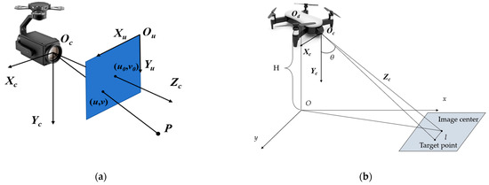
Figure 3.
Quadrotor UAV camera system positioning-related coordinate system. (a) The positioning relationship between the UAV camera coordinate system and the pixel coordinate system. (b) The depth calculation model for the UAV camera.
2.3. Design of SDCM for Camera Position Error Correction in a Small Quadrotor UAV
Generally, the main optical axis of the camera is set as the Zc-axis, and the Xc-axis and Yc-axis are set with reference to the image coordinate system. The coordinate system relationship is shown in Figure 3a. The attitude angle of UAV camera is (α, β, γ), the heading angle α is the angle around the Yc-axis, and the right deviation is positive; the pitch angle β is the angle around the Xc-axis, and upward is positive; the roll angle γ is the angle around the optical axis Zc, and right roll is positive. The three-dimensional point transformation in two-rigid-body coordinate systems needs to be carried out through the rotation matrix. Since the camera is mounted under the UAV body, there is no clear rotation order. The preliminary conversion from the camera coordinate system to the UAV body coordinate system relies on a Rz-y-x-order rotation matrix. Here, we refer to the UAV rotation definition Rz-y-x (axial order) to set the matrix. The preliminarily set target conversion formula, including the rotation matrix, is shown in Equation (2).
where (xc, yc, zc) and (xd, yd, zd) represent the target point coordinates in the camera coordinate system and the drone coordinate system, respectively. Rz-y-x is the camera attitude combination rotation matrix we use for rigid body coordinate system conversion, which is set in the order of z-y-x. The selection of the Rz-y-x rotation sequence is based on the physical working logic of the drone and camera. This heading pitch roll operation sequence is consistent with the timing of the attitude angle output by the gimbal sensor. Therefore, the rotation matrix is constructed in the right multiplication order of Rz Ry Rx, which can directly match the physical meaning of hardware data. Different rotation conventions can impact results. For instance, internal rotation within a coordinate system necessitates reversing the order of matrix multiplication, which may amplify coordinate deviation errors under large attitude angles. The external rotation sequence used in Equation (2) not only conforms to the physical intuition of drone operation but is also consistent with the previously derived single-axis matrix multiplication logic, ensuring the accuracy of camera-to-drone coordinate conversion.
However, in practical applications, because the conventional small quadrotor UAV usually places the camera pan tilt under the front of UAV body, as shown in Figure 4, it is generally close to the nose gear or nose (such as DJI mavic series UAVs), and the origin of the UAV coordinate system is always defined in the center of gravity of UAV or the symmetrical point of body center. The different assembly centers of the two coordinate systems lead to a fixed spatial offset error between the camera coordinate system and the coordinate origin of the UAV coordinate system, which in turn affects the target positioning accuracy after multiple transformations.
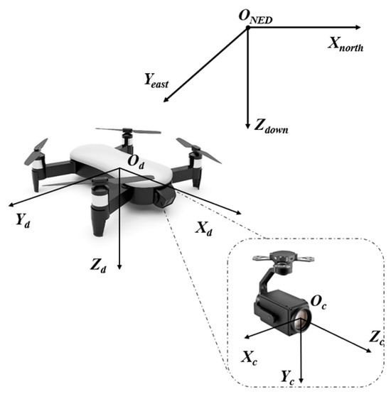
Figure 4.
Schematic diagram of the position deviation between the quadrotor UAV coordinate system and the camera coordinate system.
- Analysis of camera offset error on overall positioning accuracy
Each transformation in the multi-level coordinate transformation chain is a key link involving the positioning results, and the existing errors will be magnified step by step through the coordinate transformation and ultimately have a significant impact on the positioning results in WGS84 coordinates. In small quadrotor UAV applications, failing to account for the fixed offset vector ΔT of camera placement during camera-to-UAV coordinate conversion introduces systematic errors caused by the fuselage structure in this step and all subsequent coordinate conversions. By analyzing the steps of the multi-level coordinate system transformation algorithm designed above, assuming that there is no offset, the transformation process of the target space point from the camera coordinate system (xc, yc, zc) to the UAV coordinate system (xd, yd, zd) is obtained by building the rotation matrix based on the camera motion attitude angle. The simplified formula can be shown in Equation (3).
where Pc and Pd represent the coordinates of the target in the camera coordinate system and the UAV coordinate system, respectively. The symbol Rc is the rotation matrix constructed based on the attitude angle of the PTZ camera. The above formula holds only if the camera coordinate system origin Oc and the UAV body coordinate system Od are at the same position or approximately the same position.
However, the reality of the application of the small quadrotor UAV is that the position of the target point in the camera coordinate system is relative to Oc. When we want to describe its position in the UAV coordinate system Od, we first need to convert it to a coordinate system parallel to Od and then apply the translation ΔT from Oc to Od. Therefore, the correct conversion relationship of the target from the camera coordinate system to the UAV coordinate system should be as shown in Equation (4).
After the designed multi-level coordinate system transformation algorithm is subject to the practical application, the error will be amplified along the coordinate system transformation chain in turn. After mistakenly using Pd_estimated = Rc∙Pc instead of the real Pd_true = Rc∙Pc + ΔT, the coordinates in the UAV coordinate system directly generate the error of ΔPd = Pd_estimated − Pd_true = ΔT. This fixed error will exhibit attitude dependence in the subsequent conversion process due to changes in the UAV’s attitude angle. And this attitude dependence of fixed error will continue to interfere with the subsequent calculation process, ultimately affecting the positioning accuracy. When converting the coordinates of the target UAV to the NED coordinate, it is necessary to construct the rotation matrix with the help of the attitude angle (ϕ, θ, ψ) (yaw, pitch, roll) of the UAV. Equations (5) and (6) show two kinds of calculation equations for real conversion and estimated conversion:
where Rd is the rotation matrix constructed based on the above UAV attitude angle, which is set in the order of z-y-x. The calculation logic of the conversion formula here is similar to Equation (2). Through the comparison of the above two formulas, it can be analyzed that the error vector ΔT caused by ignoring the camera offset will be further enlarged in the next conversion. This further affects the calculation accuracy of the actual NED coordinates of the target. The position error ΔPNED = PNED_estimated − PNED = −Rd∙ΔT in the NED coordinate system is further affected by the UAV body attitude rotation matrix Rd. The impact of this error is more dependent on the UAV’s body attitude angle, which further underscores the attitude-dependent nature of the camera offset error during multi-coordinate transformation.
In the three-dimensional attitude angle of the UAV, the yaw angle mainly affects the direction and the distribution of Tx and Ty in the northeast plane. When the UAV fuselage state is horizontal, the calculation result of (Roll = 0, Pitch = 0) Rd is the unit array. The error ΔPNED is approximately equal to −ΔT. The error effect is mainly in Tx (north direction), Ty (east direction), and Tz (ground direction). When the UAV has a roll angle, Rd will change the projection ratio of Ty and Tz in the horizontal plane (northeast) and vertical direction (ground), while when the UAV has a pitch angle, Rd will significantly change the projection ratio of Tx and Tz in the horizontal plane and vertical direction. These angle changes from the UAV fuselage attitude will have a great impact on the horizontal distance (especially the forward distance) and height calculation of the target point.
This front pan tilt offset error, which starts from the camera coordinate system, continues to undergo the continuous conversion of NED-ECEF-WGS84 after the change and amplification of UAV fuselage angle (the subsequent conversion mainly relies on the formulas for scale transformation and projection calculation), and the final error will be directly mapped to the final longitude, latitude, and height. The front pan tilt offset ΔT will be significantly amplified by the UAV attitude rotation matrix, resulting in systematic deviation in the horizontal position (especially the distance along the UAV heading) and altitude positioning of the target point. The magnitude and height of the deviation depend on the current attitude angle of the UAV. Although the uncompensated ΔT error is at the centimeter or decimeter level, in the actual flight mission of a quadrotor UAV, the amplification effect of a small deviation in attitude rotation may cause the final positioning error to be further enlarged on the original basis.
- Design of 3D coordinate error SDCM for the camera
In order to overcome the influence of camera installation deviation on subsequent continuous conversion, we introduce the explicit offset vector ΔT = [Δx, Δy, Δz]T in the previous camera to UAV coordinate system conversion to represent the offset compensation of the camera installation center point in the UAV coordinate system. For the design of the camera error compensation model of the three-dimensional correction vector ΔT, we fuse the flight state and environmental perception data based on the fuselage structural parameters of the quadrotor UAV. The core idea of the camera position compensation model is to decompose the compensation amount into two parts: structural deviation and dynamic deviation. The structural deviation is usually determined by the manufacturing structure and installations of the quadrotor UAV, which can be obtained through the fuselage parameters of the UAV. The dynamic deviation is related to the attitude and other factors of the quadrotor UAV during flight and is updated in real time through physical modeling. To address the above issues, we have designed a compensation model (i.e., SDCM) based on the fuselage structure of a small quadrotor UAV. This model relies solely on known or estimable basic fuselage parameters of the UAV and basic parameters of the front PTZ camera.
Under general design conditions, the structure of the common small quadrotor UAV is usually rigid, and the camera pan tilt of the UAV is firmly connected with the base of the UAV, so ΔT is generally a fixed offset vector. For a stable flight, the UAV body usually has good symmetry, and its center of gravity is generally located at the geometric center of the fuselage, which is the defining origin of the UAV coordinate system. For ΔT, it is usually a three-dimensional vector, and each component corresponds to the deviation value of the camera in the corresponding dimension. According to the flight status of the drone, it can be divided into ΔTstruct and ΔTdynamic errors. The analysis of ΔTstruct in three dimensions can be calculated through the parameters of the drone itself. The symbol Δx denotes the longitudinal offset of the PTZ camera center Oc relative to the UAV center of gravity Od. For a common four-rotor UAV, the PTZ camera installation center is usually very close to the leading edge of the fuselage, and the structural deviation of Δx is the difference between the distance L from the head of the UAV to the center of gravity of the fuselage and the distance D between the head and the PTZ camera center. The symbol Δy is usually installed symmetrically on the left and right sides of the UAV body and PTZ camera, so the theoretical value in this dimension is almost 0. The symbol Δz represents the vertical offset of the PTZ camera center Oc relative to the UAV’s center of gravity Od. This value can be estimated by the difference between the overall height h of the fuselage in the deployed state and the distance h between the PTZ camera center and the bottom of the rotor frame. The above parameters can be obtained from the UAV’s technical parameters and simple measurement. Based on the above analysis, the overall expression for the structural deviation component of ΔTstruct is derived as shown in Equation (7).
For the dynamic deviation compensation of UAV, ΔTdynamic can be seen from the above analysis and derivation of camera offset error on the overall positioning accuracy, whose deviation is mainly caused by the subsequent body rotation matrix. In order to compensate for the projection difference in structural error caused by the UAV attitude at this stage, a dynamic offset compensation is introduced, and the compensation is defined as Equation (8). The dynamic offset compensation of Equation (8) is derived by subtracting the ideal projection of the static offset ΔTstruct (Standard Matrix I) from the true projection obtained from the UAV attitude rotation matrix Rd:
This compensation is set up to process the dynamic error vector of the structural deviation affected by the UAV attitude in the real flight state. The symbol Rd∙ΔTstruct is the true projection of structural offset in the NED coordinate system, and ΔTstruct is the offset in the ideal state. Since the matrix Rd has fully reflected the rotation relationship of the UAV body, the dynamic offset compensation amount needs to be constructed with the help of the rotation matrix of the UAV attitude angle. The complete rotation matrix Rd formula is shown in Equation (9). The attitude rotation matrix Rd of the drone in Equation (9) is obtained by multiplying the single axis external rotation matrix of the yaw angle ϕ around the Z-axis, the pitch angle θ around the Y-axis, and the roll angle ψ around the X-axis in the order of Rx(ψ) Ry(θ) Rz(ϕ) and then unfolding the matrix elements:
According to the above rotation matrix description and derivation process, the multi-dimensional expansion of dynamic deviation compensation can be expressed as Equations (10)–(12).
where Rij corresponds to the matrix elements of each row and column of the rotation matrix Rd.
Based on the above derivation, the formula designed for SDCM is Equation (13).
The formula of the conversion steps from the camera coordinate system to the UAV coordinate system designed by us is also improved by Equation (14).
where the static part of ΔTtoatl is calculated by the above method based on basic parameters and is used as a constant under stable flight conditions. When the UAV attitude deviation occurs, it will be stabilized by the dynamic compensation so as to ensure the subsequent stable calculation of the target position.
The uncertainty of ΔTstruct mainly comes from the measurement error of its core parameters. Among them, L and D are measured using a laser rangefinder (accuracy ± 1 mm), H is referenced from the DJI M3T official technical manual (nominal value 139.6 mm, accuracy ± 0.1 mm), and h is also obtained using a laser rangefinder (accuracy ± 0.5 mm). Since the components of ΔTstruct (Δx = L − D, Δy, Δz = H − h) are obtained by combining these parameters, measurement errors will affect the final static compensation through component superposition: for example, the error of Δx is determined by the measurement errors of L and D together, while the error of Δz comes from the error superposition of H and h. According to the comprehensive calculation, the total uncertainty of the static deviation ΔTstruct is about 1.43 mm. This millimeter-level error indicates that by strictly controlling the accuracy of the measurement tool, the systematic error of the static compensation link can be effectively limited to a small range, and the impact on subsequent coordinate conversion is controllable.
The uncertainty of ΔTdynamic is mainly related to the attitude noises of unmanned aerial vehicles, and its core is the error transfer effect of the attitude rotation matrix Rd. The original attitude angle of the drone is affected by near-ground wind disturbance, motor vibration, and other factors, resulting in random noise of ±0.5°. This type of noise can cause deviation in Rd, which in turn distorts the projection correction effect of dynamic compensation on static deviation. Due to the coupling calculation of Rd and static deviation, the reduction in Rd error directly reduces the uncertainty of dynamic compensation, ensuring the stability and reliability of dynamic deviation correction.
It is expected that after introducing SDCM based on the basic parameters, the fixed spatial offset error caused by the non-coincidence of the origin will be corrected by explicitly adding error parameters in the conversion step from the camera coordinate system to the UAV coordinate system. This makes the point coordinates Pd_estimated in the UAV coordinate system, calculated later, closer to the real value Pd_true than those calculated without compensation. On this basis, the dependent errors caused by subsequent UAV attitude changes will also be further reduced. In theory, the addition of the compensation model vector eliminates the systematic positioning deviation caused by the camera and UAV origin offset ΔT itself and its amplification under the attitude rotation matrix. In practical applications, it can also greatly reduce the positioning deviation caused by not considering the camera offset.
After completing the conversion of the target from the camera coordinate system to the UAV body coordinate system, it needs to be further transformed into the NED coordinate system. The Xd-axis of the UAV body points to the nose, the Yd-axis points to the right side of the body, and the Zd-axis points down. Its attitude angle is (ϕ, θ, ψ). Referring to the NED coordinate system, the heading angle ϕ is the rotation angle around the Zd-axis, and the right deviation is positive. The elevation angle θ is the rotation angle around the Yd-axis, and upward is positive. The roll angle ψ is the rotation angle around the optical axis Xd-axis, and the right roll is positive. The conversion from the UAV coordinate system to the NED coordinate system is performed by rotating to a fixed coordinate axis, and the formula is shown in the following Equation (15).
2.4. Three-Dimensional Earth Model Setting and World Coordinate System Transformation
As for the relationship between the ECEF coordinate system and the NED coordinate system, as shown in Figure 5, after the target point is represented in the NED coordinate system, the rotation matrix needs to be constructed with the help of the UAV longitude and latitude coordinates (φd, λd, hd) in the WGS84 coordinate system. Then, these UAV longitude and latitude positions in the WGS84 coordinate system are converted to ECEF as the reference point for subsequent target conversion so that the target point can be converted into three-dimensional coordinates (xecef, yecef, zecef) in the ECEF coordinate system for subsequent calculation, and the conversion is shown in Equation (16).
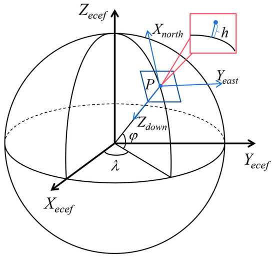
Figure 5.
Relationship between the quadrotor UAV airframe in the ECEF coordinate system and the NED coordinate system.
As a coordinate system based on the reference ellipsoid, the origin of the ECEF is in the center of the ellipsoid. In this coordinate system, it is more convenient to calculate in three-dimensional space, which makes it easier to deal with three-dimensional coordinates in the global position. By setting the equatorial radius, oblateness, and other parameters of Earth, a three-dimensional simulation model of the ellipsoid shape of Earth is constructed, and the longitude and latitude (φd, λd, hd) of the UAV are converted according to Equations (17) and (18) and brought into the ellipsoid model for calculation. Then the coordinates of the UAV in the ECEF coordinate system can be established to assist in solving the ECEF coordinates of the target point in Equation (16) above.
After obtaining the coordinates (xecef, yecef, zecef) under the ECEF coordinate system of the target point, the actual longitude and latitude information can be obtained according to the conversion relationship between WGS84 geographical coordinates and ECEF. According to the above settings and the establishment of a three-dimensional Earth model, the latitude and longitude can be calculated according to the arctangent function, and the three-dimensional ECEF coordinates of the target point can be converted to the final WGS84 coordinates (φ, λ, h). This completes the process of converting from pixel coordinates to WGS84 coordinates. The conversion formula from the geocentric geostationary coordinate system to WGS84 coordinates is derived as shown in Equation (19).
Similarly, N’ in Equation (19) can be solved by Equation (20). In the calculation process, it is noted that φ and h of the target point are coupled in the formula solution. In general, numerical iteration is usually used for calculation, and the Newton–Raphson [40] method is commonly used.
2.5. Attitude Filtering Algorithm: Design and Principle of Block IEKF
In the actual flight process of the UAV, the near-ground wind speed interference and other environmental factors often affect the attitude of the UAV and the PTZ camera and then affect the final positioning accuracy of ground targets. And the impact of environmental interference is not the same on UAVs of different types and materials. For example, the light fixed-wing UAV is severely disturbed by the ambient wind, while the four-rotor small UAV has relatively stable flight state control due to the presence of multiple rotors, but it will still lead to attitude fluctuations. In the dynamic environment of actual flight, the input of the algorithm susceptible to environmental interference is mainly the attitude angle of the UAV and the PTZ camera. Because the whole target positioning conversion algorithm is based on the angle-based coordinate system conversion, any small angle changes will affect the positioning accuracy.
In order to reduce the attitude interference, based on the Kalman filter theory [41], a multi-dimensional block-iterative extended Kalman particle filter attitude filter is designed to effectively filter the attitude interference caused by environmental factors. A block filtering method is designed for the six-dimensional attitude angle (pitch, roll, and yaw angles) filtering of UAV and PTZ camera. First, based on the block independence assumption, the UAV attitude is modeled and initialized. In the scene of wind speed jitter interference, the dynamic evolution of each dimension’s attitude angle is independent of the others. Second, an iterative extended Kalman filter (IEKF) is applied independently to each angle dimension to generate the importance density function. Finally, sampling is performed based on the posterior estimation of the IEKF iterative correction output, and the noises of each single dimension are suppressed by weight update and resampling. In view of the fact that the rotor UAV is vulnerable to many disturbances such as wind speed, airflow, and periodic jitter of motor equipment in the actual flight process, which leads to the six-dimensional attitude angle of UAV being disturbed by noises, we use the six-dimensional attitude filter designed for this problem to filter the six-dimensional attitude data of the disturbed UAV and compare the filtering effects of various existing filters on the data. Based on the six-dimensional attitude data of the UAV that have been recorded stably for a period of time, we add the noise interference in line with the situation to the data as the basic data to be filtered.
3. Experiment Results
In this paper, a series of experiments are carried out to verify the whole process of the proposed algorithm. The relevant experiments are carried out using Python programming on a Windows 11 operating system computer, the CPU model is Intel(R) Core(TM) i7-14650HX CPU@2.20 GHz, the graphics card is NVIDIA GeForce RTX 4070 Laptop, the RAM is 16 GB, the development environment is Python 3.9, the pytoch framework is 1.9.0, and the CUDA version is 11.3.
3.1. Experimental System and Dataset
In our experiment, a DJI M3T small quadrotor UAV is used to capture and collect target images. The hardware parameters of the UAV are shown in Table 1 below. At two shooting altitudes of 25.0 m and 35.0 m close to the ground, the ground targets placed in different positions are photographed at three conventional search angles of 45°, 60° and 90°. To better simulate UAV rescue scenarios, the UAV’s video recording function is used to capture ground target videos at various altitudes after the UAV stabilizes, and images are extracted from the recorded videos. Three images with different target positions are selected from each angle, and the size of a single frame image is 1920 × 1080. We use Zhang’s calibration method [42] and a black-and-white calibration plate to calibrate the UAV recording camera and then obtain the parameters of the UAV camera internal parameter matrix. In order to verify the positioning effect of our algorithm, we use a hand-held differential real-time kinematic (RTK) locator to record the real WGS84 coordinates of each target point.

Table 1.
The hardware parameters of our UAV (DJI M3T).
The ground target to be located is a pre-drawn circular target with a diameter of 2.0 m, as shown in Figure 6 below. We annotate 200 target images obtained from extracted video frames using Labelme [43]. The 200 annotated images are randomly split into a training set (160 images, 80%) and a validation set (40 images, 20%) without overlap. The YOLOv5s model is adopted, with key hyperparameters configured as follows: input image resolution 640 × 640, batch size = 16, optimizer AdamW (weight decay = 0.0005), initial learning rate 0.001 (decayed via cosine annealing over training epochs), and weights initialized with YOLOv5s pre-trained on the COCO dataset. After 100 rounds of iterative training, the YOLOv5 target recognition network can stably recognize image targets. The central pixel of the recognition frame can be basically located at the center of our target. In the subsequent positioning, only the central pixel will be retained and used as the subsequent algorithm input. Our algorithm validation will use the filtered images shown in Figure 7.
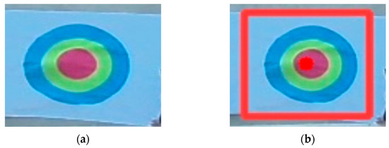
Figure 6.
Ground target recognition sample and recognition effect image. (a) means the display of the target in the image; (b) is the effect diagram after applying the recognition algorithm.
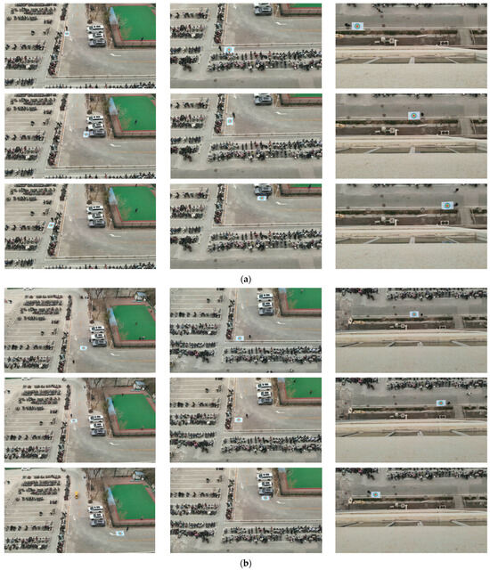
Figure 7.
UAV-collected target imaging samples pending localization. (a) shows the image samples captured at a height of 25.0 m; (b) shows the image samples captured at a height of 35.0 m. The search angles of image samples in (a,b) from left to right are 45°, 60°, and 90°, respectively.
3.2. Evaluation of Proposed Computational Method
Based on the above captured target images, we can carry out the calculation experiment verification of three processing steps of our algorithm in turn. This conversion step of the target point in the UAV camera system mainly comprises converting the two-dimensional image target pixel point into the three-dimensional image space coordinate point in the UAV camera system, which is used to participate in the subsequent calculation process. The coordinate results under the UAV camera system, calculated by target points at each angle taken at the above two flight altitudes, are shown in Table 2 below. It can be found from the results in Table 2 that after the conversion under the UAV camera system, the obtained target pixels are transformed into three-dimensional coordinates represented by the camera coordinate system, the first two coordinates are the converted X-axis and Y-axis coordinates, and the Z-axis coordinates are the depth of the target, which are calculated by the trigonometric function estimation of camera parameters and UAV altitude and pitch angles. After the transformation in this step, the obtained 3D target points are the position expression of the target to be located in the camera system.

Table 2.
The conversion calculation results of target pixels at heights of 25.0 m and 35.0 m in the UAV camera system (Unit/m).
After completing the conversion of target points in the UAV camera system, the next step is to continue the coordinate conversion of target points from the camera system to the UAV system. The conversion process needs to rely on the three-dimensional attitude angle of the camera pan tilt and the three-dimensional attitude angle of the UAV. The target point is finally represented in the NED coordinate system through two calculation links: the conversion from the camera coordinate system to the UAV coordinate system and the conversion from the UAV coordinate system to the NED coordinate system. In this calculation step, we compare the calculation results of our SDCM and the non-SDCM, i.e., without SDCM, and obtain the further calculation results of target spatial coordinate points under the UAV camera system in the previous step under two conditions. The coordinates of each point are recorded in Table 3 below. By analyzing the coordinate point data in Table 3, the three-dimensional coordinate points of the target are converted under two coordinate systems to complete the conversion from the camera system to the UAV body system. After comparing the coordinate results before and after applying our SDCM, the coordinate points corrected by the camera position compensation model show significant accuracy improvements; meanwhile, the coordinates on the Y-axis and Z-axis are also adjusted numerically after the model modification, which is basically consistent with the estimated correction calculation results of our SDCM. After the conversion in this step, each target point has been transferred to the UAV coordinate system for expression.

Table 3.
The conversion result samples at 25.0 m and 35.0 m altitude from the UAV camera system to the UAV body system before and after the application of our camera position compensation (Unit/m).
After completing the first two steps, the target point can be transferred to the UAV body system for expression. The final step is to convert the calculated target point into latitude and longitude coordinates under a geodetic ellipsoid model. This process takes the position of the UAV as a reference and calculates the final latitude and longitude results through the above process. Figure 8 and Figure 9 show the calculation results of the targets at two heights and different angles before and after the application of our SDCM. The target pixel and its corresponding latitude and longitude calculation results are marked on images. In order to display the results more intuitively in the paper, we present the latitude and longitude calculation results of each target below each image. At the same time, in order to compare the accuracy of the multi-level coordinate system positioning algorithm before and after applying our SDCM, we use a handheld centimeter-level locator to measure the actual longitude of the target as benchmarks for subsequent accuracy comparisons.
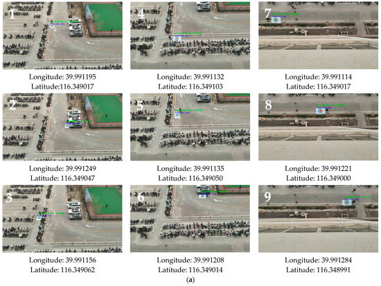
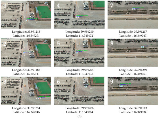
Figure 8.
The experimental localization results without our camera position compensation. (a) shows the final calculated positioning results at a height of 25.0 m of the overall conversion algorithm without our camera position compensation. (b) shows the final calculated positioning results at a height of 35.0 m of the overall conversion algorithm without our camera position compensation. The numbers 1–9 from left to right are the recognition results of targets at different positions at angles of 45°, 60°, and 90°, respectively.
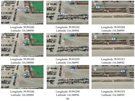
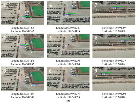
Figure 9.
The experimental localization results after using our SDCM. (a) shows the final calculated positioning results of the overall conversion algorithm with our camera position compensation for a height of 25.0 m. (b) shows the final calculated positioning results of the overall conversion algorithm with our camera position compensation for a height of 35.0 m. The numbers 1–9 from left to right are the recognition results of targets at different positions at angles of 45°, 60°, and 90°, respectively.
Based on the calculation results shown in Figure 8 and Figure 9, the image target pixels can be roughly solved based on the latitude and longitude coordinates of the UAV after multiple conversions. In order to verify the positioning accuracy before and after applying SDCM, we compare the actual latitude and longitude measured by data collection with the calculated results from two experiments and obtain the position deviation between the corresponding experimental calculation points and the actual points. In the calculation of point deviation, a general latitude and longitude approximation is adopted, where the fifth decimal place of the latitude and longitude represents the meter level. The point map and error deviation plot of the calculation results are shown in Figure 10.
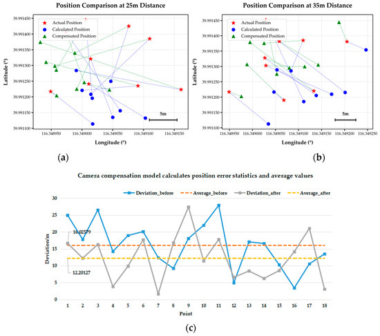
Figure 10.
The calculation, positioning, and overall result analysis of the multi-level coordinate system conversion algorithm before and after the application of our camera position compensation at a height of 25.0 m and 35.0 m. (a) shows the positioning results for shooting at a height of 25.0 m using a multi-level coordinate system conversion algorithm before and after the application of our SDCM. (b) shows the positioning results for shooting at a height of 35.0 m using a multi-level coordinate system conversion algorithm before and after the application of our camera position compensation. (c) represents the statistical line chart of error between the experimental target position and the calculated position before and after the application of our model.
Figure 10 shows the positioning and analysis results before and after applying our SDCM. Figure 10a,b show the positioning results at heights of 25.0 m and 35.0 m, the red pentagrams represent the actual target coordinates, the blue circles represent the target coordinates calculated by the algorithm without our compensation model, the green triangles are the overall algorithm calculation result after passing through our SDCM, and the blue and green dashed lines mean the distance difference between their respective calculation results and the actual latitude and longitude points. From Figure 10a,b, it can be observed that with the addition of our compensation model, the basic overall algorithm can roughly solve the latitude and longitude value range of the UAV, but the spatial distribution is discrete, and most target points have deviations. Moreover, the longitude span of the 35.0 m altitude calculation point is larger, indicating that the altitude increase changes the calculation range area of the positioning model. After introducing the SDCM, the error can decrease for both 25.0 m and 35.0 m heights. The error distance represented by the green dashed line is further shortened compared to the blue dashed line, and the spatial positioning is closer to the actual position. The distribution of the coordinate calculation points after using our model is similar to the calculation results before adding, indicating that the application of the compensation model only corrects errors and does not disrupt relative spatial relationships.
Figure 10c represents a statistical line graph of errors between a total of 18 target positions and the calculated positions and computes the absolute and average positioning errors under two experimental results. From the display effect of the absolute value (the blue dashed line) and average error (the orange dashed line) of the positioning error without adding the SDCM, the calculation result has a reference mean error of 16.02579 m. However, the absolute value (the gray dashed line) and average error (the yellow dashed line) of the positioning error after adding SDCM are reduced to 12.20127 m compared to the calculation result with basic camera compensation, and the average positioning accuracy is improved by ~23.8%. Compared to the basic algorithm, after camera compensation, except for a few area points, the target calculation results have lower errors and are closer to the accurate actual coordinate points. This indicates that after the correction of SDCM, the basic process algorithm error has been effectively reduced, and it can play a role at heights of 25.0 m and 35.0 m and multiple conventional perspectives, weakening the limitations on application conditions and further improving the accuracy of positioning results.
In order to further compare the performance of our proposed SDCM method in multi-level coordinate system conversion methods, we introduce the coordinate processing method of affine transformation as a supplementary comparative experiment in the same compensation position as SDCM. This method is a universal method in coordinate system conversion processing, and our designed SDCM also refers to this idea in the static design part, which is to improve the coordinate correction accuracy by correcting the camera deviation. The settings, data sources, and evaluation scenarios during the experimental process are consistent with the previous section to ensure fairness and comparability of the comparison. The actual target point calculation results under different algorithms are shown in Table 4 below. At the same time, in order to longitudinally compare the performance improvement effect of our designed model and the basic affine method on the baseline method, we use mean absolute error (MAE), root mean square error (RMSE), standard deviation (SD), accuracy improvement rate, and 95% confidence interval (CI) of each model. The corresponding calculation formulas are shown in Equations (21)–(25), and Table 5 shows the performance comparison of the designed models:
where n is the number of samples; ei is the error between the calculated value of the i-th sample and the true value; is the sample mean of the error, MAEbaseline and MAEmethod are the average absolute errors of the benchmark model and the target model, respectively; and t represents the two-sided critical values of the distribution, representing the upper and lower bounds.

Table 4.
The calculation results of different models’ multi-level coordinate systems after our camera compensation at 25.0 m and 35.0 m altitudes are compared with the actual longitude and latitude.

Table 5.
Coordinate Calculation Performance under Different Models.
Based on the results of the performance comparison table, as the core of measuring the performance of the coordinate transformation model, the MAE in the error indicator reflects the overall average deviation, while the RMSE is more sensitive to large errors, and both jointly determine the actual positioning accuracy of the model. The MAE (12.20 m) and RMSE (13.90 m) of SDCM are both the lowest, reduced by 3.82 m and 3.48 m, respectively, compared to the baseline model, and reduced by 1.82 m and 1.29 m, respectively, compared to the traditional affine model. Not only is the average positioning deviation smaller, but the ability to suppress extremely large errors is also better, reflecting the significant improvement of the baseline method. The accuracy improvement rate of SDCM reaches 23.86%, which is nearly twice that of the affine model at 12.50%, reflecting the accuracy improvement of SDCM in multi-level coordinate system baseline methods compared to traditional linear transformations. The 95% confidence interval is [8.79 m, 15.61 m], which is overall lower than the baseline model and affine model processing effects. The range of the interval is more controllable, proving that its performance advantage is statistically significant. Even though the standard deviation of SDCM (6.67 m) is slightly higher than that of the affine model, its absolute range of error fluctuations is narrower and overall downward, balancing high accuracy and stability. Overall, SDCM achieves leadership in accuracy and robustness, making it an advanced coordinate transformation model more suitable for drone target localization in complex scenarios.
The Figure 11 reveals the error characteristics of the model from the statistical distribution dimension. The median (orange line) of SDCM is significantly lower than Babaseline and affine, indicating that its typical positioning error is smaller and that it can output more accurate results in most scenarios. The error interval (box) of the middle 50% of the samples is more compact, indicating that the error distribution of SDCM is more concentrated and consistent. The extension range of extreme errors is significantly shorter than the baseline, and the ability to suppress large errors is better. On the other hand, the baseline has a wide box, high extreme values, and significant fluctuations in error. Although the affine transformation processing is similar to SDCM, the median is still higher than SDCM, indicating insufficient control of typical errors. From the above analysis, it can be concluded that SDCM exhibits significant advantages in typical error size, error distribution concentration, and extreme error suppression. Its stability far exceeds the baseline, and its accuracy performance in most samples is superior to the same affine transformation processing.
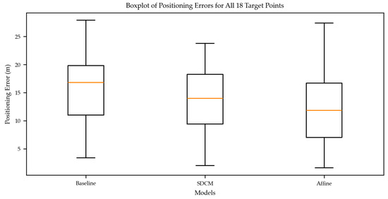
Figure 11.
Box plot of positioning errors for 18 target points under different models.
Figure 12 compares the MAE performance of the model from the perspective of scene universality at heights of 25.0 m and 35.0 m and shooting angles of 45°, 60°, and 90°. At a height of 25.0 m, the MAE of SDCM is the lowest among the three types of models at angles of 45° and 60°. For example, at an angle of 45°, it is about 7.0 m lower than the baseline and about 4.0 m lower than the affine transformation processing. At a height of 35.0 m, the advantage of SDCM also runs through all angles, and at an angle of 60°, it is about 7.0 m lower than the baseline and about 3.5 m lower than the affine, fully reflecting its accuracy advantage in conventional scenes. In the extreme scenes shot vertically at 90°, although the SDCM results at 25.0 m and 35.0 m heights are slightly higher than those of baseline and affine, this scene is the most challenging condition for all models due to the large perspective deformation and easy amplification of errors, while the SDCM remains optimal in the other four scenes (two heights and two conventional angles). From the overall result presentation, the SDCM processing has the corresponding precision progressiveness and scene universality in most practical scenes.
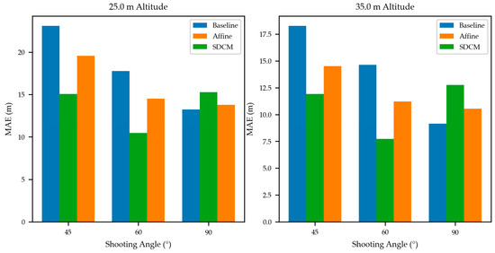
Figure 12.
MAE bar chart of models at different heights and shooting angles.
3.3. Evaluation of the Effectiveness of Designing Filters
To verify the effectiveness of our designed BlockIEKF filter, we adopt four kinds of noise signals. The basic Gaussian noises are used to simulate the background noises of the sensor, and the uniformly distributed noises are used to simulate system errors. The impulse noises with a probability of 2.0% and a maximum disturbance amplitude of 3 degrees is used to simulate the sudden wind disturbance of the UAV, and the periodic vibration noises with a vibration frequency of 5.0 Hz and an amplitude of 0.3 degrees to simulate the vibration of the motor or quadrotor propeller. Finally, the signals superimposed by the above types of noise signals are used to simulate the attitude of the UAV after the interference of environmental factors in the actual flight. In terms of filter effect evaluation, we use the designed six-dimensional UAV attitude filter to filter the six-dimensional basic data, and at the same time, we use the basic particle filter (BasicPF) and Kalman filter, as well as the moving average filter with good real-time performance to perform the same filtering operation on data, and then make the same evaluation on the filtering effect of filter. The evaluation indicators adopted include MAE, RMSE, normalized root mean squared error (NRMSE), signal-to-noise ratio (SNR) [44], noise reduction [45], and smoothness. The calculation formulas of each index are shown in Equations (26)–(29).
where represents the original data points; is the filtered data points; means the data points after adding noises; and represent the maximum and minimum values of original data; n is the number of recorded data points; and Var is the variance calculation function. The indicators above can better measure the filtering effect of the filter on UAV attitude angle data. The overall experimental effects of each filter are shown in Figure 13 and Figure 14 below.
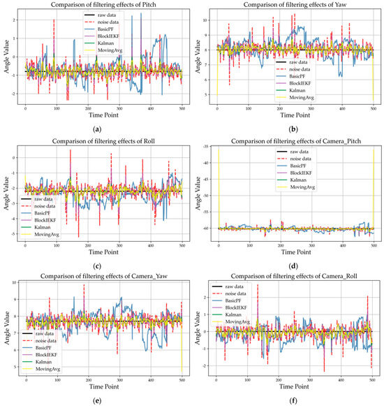
Figure 13.
Comparison of the filtering effect among the six-dimensional attitude filtered by four types of filters and original noise data. The sequences from (a–f) are the pitch angle, yaw angle, roll, camera_pitch angle, camera_yaw angle, and camera_roll angle, respectively.
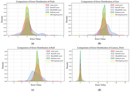
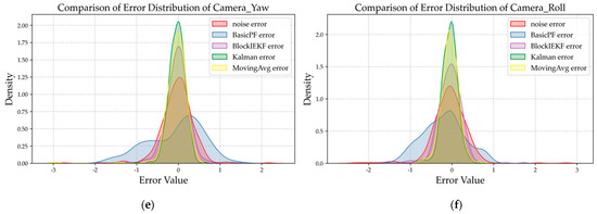
Figure 14.
Data error distribution curve of six-dimensional attitude raw noise data after filtering via four filters. The sequences from (a–f) are pitch angle, yaw angle, roll angle, camera_pitch angle, camera_yaw angle, and camera_roll angle, respectively.
Figure 13 shows the filtering effect comparison of the UAV’s six-dimensional attitude and original noise data filtered by three types of basic filters and the improved BlockIEKF filter. The filtering effect diagram directly reflects the ability of a filter to restore the original attitude signal. According to the analysis of the filtering effect, the MovingAvg filter in the basic filter only averages the attitude data, and the processing time is almost zero. However, in the filtering effect of signals such as the yaw signal and the camera_pitch signal, it can be found that the filter is prone to long tail large errors at the beginning and end stages, which significantly affects the smoothness of the filtered signals, and the details are lost due to excessive smoothing in the middle segmentation. The filtering effect curve of the BasicPF filter fluctuates extremely violently and jumps many times, leading to poor recovery of the original signal. The traditional Kalman filter has an excellent display effect in the filtering effect diagram: its filtering curve has a high degree of fit with the original data, and most indicators in the radar map of different filter performances are in the leading position, but its long processing time will affect the real-time application of the algorithm. Our improved BlockIEKF filter combines the advantages of the basic particle filter and Kalman filter. Compared with the MovingAvg filter, the BlockIEKF filter solves the problem of sudden deviation of filtering results, and the tracking is more stable; compared with the BasicPF filter, it further enhances the ability to restore the original signal and adapts to the UAV dynamic attitude filtering scene; compared with the Kalman filter, its lower processing time can better assist the real-time operation of our multi-level coordinate system transformation algorithm.
Figure 14 presents the error distribution diagram of UAV six-dimensional attitude and original noise data filtered by three types of basic filters and the improved BlockIEKF filter. The error distribution diagram reflects the error concentration and stability of a filter. According to the analysis of error distribution, the filtering results of the MovingAvg filter are mostly concentrated in the 0 error position, and the error distribution of the filtered signal is relatively concentrated between −0.5° and 0.5°, but the long tail error further expands the overall error distribution range, greatly reducing the smoothness of the filtered signal. The error distribution diagram of the BasicPF filter shows that its effect is extremely scattered, the error distribution is wide, the error range cannot be controlled completely, and the filtering stability is seriously insufficient. The traditional Kalman filter performs excellently in the error distribution map: the density of its error at 0 is the highest among all filters, and it has good stability. We have organized the complete indicators processed by each filter as shown in Figure 15 and Table 6. Our improved BlockIEKF filter, while slightly lower than the Kalman filter in some performance indicators, is basically better than the other two basic filters. Compared with the MovingAvg filter, the RMSE of the BlockIEKF filter is 38.6% lower; compared with the BasicPF filter, it achieves the processing effect of error distribution from discrete to centralized, and its SNR, Noise_Reduction, and other indicators are superior to those of the BasicPF. Compared with the longer processing time of the Kalman filter (0.00388 s), the processing time of the improved BlockIEKF has been shortened to 0.002897 s, with a performance improvement of 25.3%, better meeting the requirements of real-time filtering.
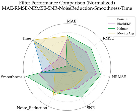
Figure 15.
Comparison diagram of different performance indexes of various filters.

Table 6.
Detailed indexes of the filtering effect of various filters.
4. Discussion
After the occurrence of natural disasters, rescue work is the key measure to protect the lives of personnel and curb the deterioration from disasters. Especially in the scenes of debris collapse, flood siege, landslide, etc., timely and accurate intervention of rescue forces is the core guarantee to avoid the loss of savable people and property due to delay. The efficiency and quality of rescue directly determine the final loss of life and property in a disaster. Efficient rescue operations can quickly stabilize the emotions of affected people, reduce panic, and lay the foundation of staff confidence for post-disaster reconstruction. However, the traditional search-and-rescue mode relying on human detection is always limited by the shortcomings of insufficient mobility and low efficiency. When facing the complex scene of large-scale disasters, it is difficult to make full use of the golden rescue window period, which may have a decisive impact on the survival probability of target personnel. In a post-disaster rescue scene, a quadrotor UAV equipped with a multi-level coordinate system transformation target positioning method based on monocular camera position compensation can carry out post-disaster personnel and target search and rescue, together with longitude and latitude positioning. It can make full use of the advantages of airspace, provide a wide range of target observation information for rescue personnel with the help of UAV pan tilt, avoid the terrain restrictions in the disaster area, and significantly improve the efficiency of target detection and localization. Clearly, the application of a small quadrotor UAV in post-disaster target search and positioning can significantly improve the efficiency of post-disaster rescue tasks, reduce the workload of search-and-rescue personnel, and avoid the potential risk of secondary disasters caused by post-disaster scenes to rescue personnel.
In the above multi-level coordinate system transformation and positioning, in the process of constructing UAV camera and UAV attitude rotation matrices, the axial rotation combination sequence of a rotation matrix is constructed in the Rz-y-x rotation sequence, which refers to the solution sequence under UAV coordinate system transformation, and this sequence is consistent with the rotation setting of the UAV fuselage. However, due to the difference between the coordinate system of the UAV camera and the coordinate definition of the UAV ontology, there is no unified setting for the conversion of the UAV camera. Therefore, we conduct a comparative test on the positioning accuracy difference of our positioning algorithm under the construction order of two different UAV camera rotation matrices, Rz-y-x (axial order) and Ry-x-z (angular order). We use the target positioning algorithm after camera compensation to measure the positioning of point targets at the same position. The experimental results and comparison are shown in Figure 16 below. Since the results of the above experiments have been calculated under the construction sequence of Rz-y-x, this result only shows the calculation results under Ry-x-z. The conversion formula from the camera coordinate system to the UAV coordinate system used in this process refers to Equation (2), as shown in Equation (30).
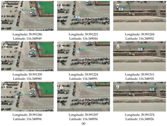
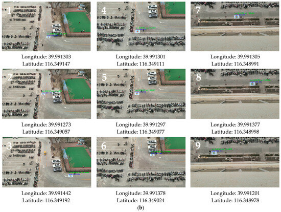
Figure 16.
Calculation results of the multi-level coordinate system transformation algorithm (with SDCM) under the Ry-x-z rotation matrix. (a) shows the calculation results for a height of 25.0 m. (b) shows the calculation results for a height of 35.0 m. The numbers 1–9 from left to right are the computational results of targets at different positions at angles of 45°, 60°, and 90°, respectively.
Figure 17 shows the calculation and positioning comparison results of the multi-level coordinate system transformation algorithm and the analysis of overall results under the rotation matrices Rz-y-x and Ry-x-z. Figure 17a shows a comparison of the overall calculation results under the rotation matrices Rz-y-x and Ry-x-z with the error difference coordinate diagram; the yellow points represent the calculation results under Rz-y-x, and the orange points are the calculation results under Ry-x-z. Figure 17b shows the statistical broken line diagram of the error size of the 18 total target positions and calculated positions, and Table 7 records the calculation results under two rotation matrices in detail. In the UAV ground target positioning task, the order of the camera rotation matrix is the core setting of the conversion relationship between the camera coordinate system and the UAV coordinate system, which directly determines the coordinate mapping logic. Based on the experimental calculation results, the difference in the effect between the two coordinate systems shows that the overall deviation is small, and the longitude and latitude directions are sensitive to differentiation.

Figure 17.
Deviation and overall result analyses of the multi-level coordinate system transformation algorithm (with SDCM) under the Rz-y-x and Ry-x-z rotation matrices. (a) shows the coordinate diagram of the error difference between the overall calculation results of the algorithm when the rotation matrix is Rz-y-x and Ry-x-z. (b) represents the statistical line chart of error between the total 18 target positions and the calculated positions in the experiment.

Table 7.
The calculation results of the Rz-y-x and Ry-x-z multi-level coordinate systems after our camera compensation at 25.0 m and 35.0 m altitudes are compared with the actual longitude and latitude.
First, from the overall effect, the deviation magnitudes of the calculation results of the two coordinate systems are small, and the core positioning performance can converge. The core positioning effects of the two coordinate systems are almost the same, and the overall deviation is in the same order of magnitude. From the statistical results shown in Figure 17b, the average positioning error under the setting of Rz-y-x is 12.20127 m, and that under the setting of Ry-x-z is 12.28035 m, with a difference of only 0.07908 m, which is far less than the basic error of the positioning system (12.0 m level). In Table 7, at 25.0 m and 35.0 m altitude, the difference between the two sets of longitude calculation values is concentrated in −0.000085° to 0.000088°, and the difference between latitudes is concentrated in −0.000151° to 0.000177°, which is lower than the meter-level positioning range. The error distribution of the 18 target points is basically consistent in Figure 17a, indicating that the reliability of the two coordinate systems is consistent under different target positions, and there is no difference in scene adaptability.
Second, from the perspective of longitude and latitude, there is obvious directional asymmetry in the effect difference between the two coordinate systems. The latitude direction is more sensitive to the rotation order, and the deviation is significantly greater than the longitude direction, reflecting the difference in the projection characteristics of coordinate system transformation. The deviation of target calculation results in the latitude direction is larger and the fluctuation is clearer. According to Table 7, the absolute value range of the latitude direction deviation is 0.000003° to 0.000177°, and the average value is 0.000089°. In the longitudinal direction, the deviation is smaller and more stable. The absolute value range of the longitudinal direction deviation is only 0.000002° to 0.000088°, and the average value is 0.000048°, which is only 53.9% of the latitude deviation. This difference is rooted in the projection logic of coordinate system conversion; i.e., when the target is converted from the NED coordinate system to the ECEF coordinate system, the north projection coefficient corresponding to the latitude direction is directly related to the radius of curvature of the Earth and is more sensitive to coordinate increment. The east direction corresponding to the longitude direction is less affected by Earth’s rotation radius, and the projection coefficient is more stable. The camera UAV coordinate system conversion error caused by the two rotation matrix sequences is amplified in the latitude direction, weakened in the longitude direction, and finally forms an asymmetric deviation.
Overall, the minor positioning difference (average error gap: 0.07908 m) between the Rz-y-x and Ry-x-z rotation orders can be attributed to two key factors: mathematical sensitivity under small attitude angles and constraints of the experimental scenario. First, in the tested conventional search angles (45°, 60°, 90°) and stable low-altitude flight (25.0–35.0 m), the quadrotor’s attitude angles (yaw, pitch, roll) exhibit minimal fluctuations (within ±5° of the set angle). For small-angle rotations, the elements of the Rz-y-x and Ry-x-z matrices differ only in second-order small quantities, and such tiny differences are barely amplified in subsequent coordinate transformations (NED → ECEF → WGS84), resulting in negligible final positioning deviations. Second, the SDCM’s dynamic compensation module partially offsets the projection error caused by rotation order differences—by correcting attitude-dependent structural deviations, the model reduces the sensitivity of the coordinate mapping to the rotation sequence.
From the perspective of engineering applications, the experimental results of two different coordinate system settings of the camera show that under general scene conditions, the camera coordinate system does not need to strictly limit the rotation order and still maintains the positioning accuracy within the controllable range. Considering the differences in the definition of the UAV camera coordinate system from different manufacturers, the compatibility of the two rotation sequences can be adapted to multiple types of cameras, and there is no need to re-develop the conversion algorithm for specific cameras, which reduces the deployment threshold of overall positioning system algorithm and also avoids the risk of sudden drop in accuracy due to the wrong rotation sequence, significantly reducing the deployment and calibration difficulty of UAV positioning system proposed in this paper.
To further verify the real-time performance of our algorithm in practical applications, we conduct real-time verification of our multi-level coordinate system transformation method (based on monocular camera position compensation for quadrotor UAVs) using the UAV target localization algorithm’s real-time verification system framework shown in Figure 18 (comprising three operation nodes: UAV PTZ camera, UAV console, and ground program processing terminal). During flight missions, the UAV captures real-time ground video, transmits the video stream back to the ground station console via user datagram protocol (UDP) network communication based on the real-time streaming protocol (RTSP), and the console then connects the video stream (from the UAV PTZ camera’s IP) to the host computer (ground terminal) using the configured internet protocol (IP) and port. The host decodes and displays the video stream, performs frame-by-frame decoding and recognition via the YOLOv5 network, displays the object recognition results, and simultaneously calculates the target’s location using our algorithm to achieve real-time video stream recognition and geographic coordinate localization. For experiments on ground target localization with actual UAV flight data, frame extraction is performed during video recognition to align the timing of the UAV fuselage information (limited by its transmission frequency) and video stream data, ensuring spatiotemporal accuracy for the algorithm. No significant frame loss or video interruption occurs during the experiment, and the video stream with localization results can be normally displayed, confirming that our proposed localization method meets real-time requirements in typical operating scenarios.
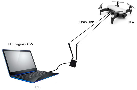
Figure 18.
Schematic diagram of the UAV target location algorithm real-time verification system framework.
The method proposed in this paper has at least the following advantages. First, the transformation method is logically closed-loop and traceable. A continuous conversion chain from pixel coordinates, camera coordinates, UAV coordinates, NED coordinates, and ECEF coordinates to the final WGS84 coordinates based on the quadrotor UAV shooting target is constructed, covering the whole process conversion logic from the image target to the global geographical coordinates. The solution can be completed only through the UAV’s own longitude and latitude, attitude angles, and camera intrinsic parameters, which reduces the cumulative risk of error caused by similar black box model conversion, and better meets the actual needs of disaster relief. Second, the two-dimensional compensation model for structural and dynamic deviations of the monocular camera significantly improves the positioning accuracy of our algorithm. It solves the common problem that the positioning accuracy of the algorithm is affected by the non-coincidence of the camera pan tilt and the fuselage gravity center of the small quadrotor UAV. The experimental verification shows that the target positioning accuracy after compensation has been significantly improved compared with that before compensation, and the coupling error between the camera and the UAV coordinate system in the coordinate conversion chain is effectively resolved. Third, this method is suitable for common small UAVs and the algorithm framework. In practical applications, it is not limited to disaster rescue tasks but can also be extended to the corresponding tasks that need to use UAVs for ground target positioning, with significant engineering universality. Clearly, our method also has some disadvantages. While the static circular targets with known centers ensure controlled evaluation of coordinate transformation accuracy, they cannot fully simulate real post-disaster environments where targets are often irregular and cluttered. In the future, experiments will expand to naturalistic targets and complex backgrounds matching real post-disaster scenarios. Typical post-disaster objects—such as casually dressed people and partially damaged vehicles—will replace the current circular markers to align with real rescue target features. Meanwhile, common disaster-zone background clutter will be added to the test field to simulate real disaster visual interference. This will verify if the positioning pipeline retains stable accuracy under non-ideal target shapes and cluttered backgrounds, strengthening the validation of its real-world rescue applicability.
5. Conclusions
This paper focuses on target positioning of ground rescue targets in post-disaster scenarios using a quadrotor UAV platform and proposes a multi-level coordinate transformation method integrated with a monocular camera position correction model (i.e., SDCM) based on quadrotor attitude compensation. First, with the help of the coordinate transformation method, the image target obtained by the recognition algorithm is transformed from two-dimensional image pixel coordinates to three-dimensional space camera coordinates. Second, aiming at the problem that the assembly error between the camera and the UAV coordinate system in the coordinate conversion system affects the target conversion of the UAV flight process, the SDCM based on the attitude angle compensation mechanism of the quadrotor UAV is established to realize the accurate conversion from camera coordinates to UAV coordinates and NED coordinates. Finally, based on the three-dimensional mathematical model of Earth and the geodetic coordinate system, a multi-level continuous conversion chain from the target coordinates to the ECEF coordinates and WGS84 coordinates is constructed. The proposed method has been tested for ground target positioning at different flight altitudes, which ensures strong implementability in practical operations with off-the-shelf quadrotors. Currently, our validation focuses on unobstructed, low-altitude open-field environments—a scenario that fully verifies the method’s core performance but also leaves room for expansion toward more complex scenarios. For instance, its adaptability to more challenging post-disaster contexts or other potential domains will require additional targeted experiments to fully validate. To address this, future work will proactively advance method optimization and scenario expansion, gradually unlocking the method’s broader application potential. In summary, the proposed method has already demonstrated clear application value in simulated low-altitude open-field post-disaster rescue tasks. As subsequent experiments refine its adaptability to complex scenarios, it is expected to gradually transition from simulated tests to practical application in quadrotor UAV post-disaster rescue missions, ultimately providing reliable technical support for improving post-disaster rescue efficiency.
Author Contributions
Conceptualization, Z.Z., H.L. (Haoting Liu), M.W., X.L. and Q.L.; Data curation, Z.Z., H.L. (Haoting Liu), Z.Y. and M.W.; Formal analysis, Z.Z., H.L. (Haoting Liu), Z.Y., M.W., H.L. (Haiguang Li) and X.L.; Funding acquisition, H.L. (Haoting Liu); Investigation, Z.Z. and H.L. (Haoting Liu); Methodology, Z.Z., H.L. (Haoting Liu), Z.Y., M.W. and H.L. (Haiguang Li); Project administration, H.L. (Haoting Liu); Resources, H.L. (Haoting Liu), Z.Y., M.W., H.L., X.L. and Q.L.; Software, Z.Z. and X.L.; Supervision, H.L. (Haoting Liu), H.L. (Haiguang Li) and Q.L.; Validation, Z.Z., Z.Y., M.W. and Q.L.; Visualization, Z.Z., Z.Y., H.L. (Haiguang Li), X.L. and Q.L.; Writing—original draft, Z.Z.; Writing—review and editing, Z.Z. and H.L. (Haoting Liu). All authors have read and agreed to the published version of the manuscript.
Funding
This work was funded by the Science Foundation of Aeronautics under Grant 2024Z074074001, the National Natural Science Foundation of China under Grant 62373042, and the Fundamental Research Fund for the China Central Universities of USTB under Grant FRF-BD-19-002A.
Data Availability Statement
The data presented in this study are available on request from the corresponding author. The data and source code for this study are available to qualified researchers upon reasonable request to the corresponding author (Haoting Liu, email: liuhaoting@ustb.edu.cn) for reproducibility. The shared data includes 200 Labelme-annotated UAV target images (captured by DJI M3T at 25.0/35.0 m altitudes and 45°/60°/90° angles), handheld RTK-measured target WGS84 ground truth, and UAV flight state logs (attitude angles, GPS position, camera PTZ angles); the source code covers YOLOv5 target detection, Static–Dynamic Compensation Model (SDCM) implementation, and multi-level coordinate transformation (pixel → camera → UAV → NED → ECEF → WGS84) modules.
Conflicts of Interest
The authors declare no conflicts of interest.
Nomenclature
| (u, v) | 2D pixel coordinates of the target in the image | Pixel |
| (u0, v0) | Pixel coordinates of the image center | Pixel |
| fx, fy | Equivalent focal lengths of the PTZ camera in the Xc axis and Yc axis directions of the camera coordinate system | Pixel |
| K | Camera intrinsic parameter matrix | Dimensionless |
| zc | Depth of the target in the camera coordinate system | m |
| Oc | Origin of the camera coordinate system | - |
| Od | Origin of the UAV body coordinate system | - |
| H | Flight altitude of the quadrotor UAV | m |
| (α, β, γ) | Camera attitude angles: α: Yaw angle (rotation around Yc-axis); β: Pitch angle (rotation around Xc-axis); γ: Roll angle (rotation around Zc-axis) | ° (Degree) |
| Rc | Rotation matrix from the camera coordinate system to the UAV body coordinate system, following the Rz-y-x (Z → Y → X) rotation order | Dimensionless |
| ΔT | Total offset vector between the camera origin Oc and the UAV origin Od | m |
| ΔTstruct | Static offset vector (fixed deviation due to UAV manufacturing/installation) | m |
| ΔTdynamic | Dynamic offset vector (compensates for attitude-induced projection errors of ΔTstruct) | m |
| Δxstruct | Longitudinal component of ΔTstruct | m |
| Δystruct | Lateral component of ΔTstruct | m |
| Δzstruct | Vertical component of ΔTstruct | m |
| Δxdynamic Δydynamic Δzdynamic | X, Y, Z-axis components of ΔTdynamic in the UAV body coordinate system | m |
| ΔTtotal | Total compensation vector (sum of static and dynamic offsets): ΔTtotal = ΔTstruct + ΔTdynamic | m |
| I | 3 × 3 identity matrix | Dimensionless |
| (ϕ, θ, ψ) | UAV attitude angles: ϕ: Yaw angle (rotation around ZNED-axis); θ: Pitch angle (rotation around YNED-axis); ψ: Roll angle (rotation around XNED-axis) | |
| L | Distance from the UAV’s nose to its center of gravity Od | m |
| D | Distance from the UAV’s nose to the camera origin Oc | m |
| H | Total height of the UAV in the deployed state (from the rotor frame bottom to the fuselage top) | m |
| h | Distance from the camera origin Oc to the bottom of the UAV’s rotor frame | m |
| Rd | Rotation matrix from the UAV body coordinate system to the NED coordinate system | Dimensionless |
| Ri,j | Element in the i-th row and j-th column of the rotation matrix Rd | Dimensionless |
| (xd, yd, zd) | 3D coordinates of the target in the UAV body coordinate system | m |
| (xNED, yNED, zNED) | 3D coordinates of the target in the NED (North-East-Down) coordinate system | m |
| (φd, λd, hd) | WGS84 coordinates of the UAV (reference point for ECEF conversion): φd: UAV latitude; λd: UAV longitude; hd: UAV altitude above the WGS84 ellipsoid | ° (Degree), m |
| (xecef, yecef, zecef) | 3D coordinates of the target in the ECEF (Earth-Centered–Earth-Fixed) coordinate system | m |
| (xdecef, ydecef, zdecef) | 3D coordinates of the UAV in the ECEF (Earth-Centered–Earth-Fixed) coordinate system | m |
| a | Equatorial radius of the WGS84 reference ellipsoid | m |
| f | Flattening of the WGS84 reference ellipsoid | Dimensionless |
| e | First eccentricity of the WGS84 reference ellipsoid | Dimensionless |
| N | Radius of curvature of the WGS84 ellipsoid in the prime vertical | m |
| N’ | Radius of curvature of the WGS84 ellipsoid in the meridian | m |
| (φ, λ, h) | Final WGS84 coordinates of the target: φ: Target latitude; λ: Target longitude; h: Target altitude above the WGS84 ellipsoid | ° (Degree), m |
References
- Xu, J.; Wang, Z.; Shen, F.; Ouyang, C.; Tu, Y. Natural Disasters and Social Conflict: A Systematic Literature Review. Int. J. Disaster Risk Reduct. 2016, 17, 38–48. [Google Scholar] [CrossRef]
- Sener, A.; Dogan, G.; Ergen, B. A Novel Convolutional Neural Network Model with Hybrid Attentional Atrous Convolution Module for Detecting the Areas Affected by the Flood. Earth Sci. Inform. 2024, 17, 193–209. [Google Scholar] [CrossRef]
- Zhou, L.; Wu, X.; Xu, Z.; Fujita, H. Emergency Decision Making for Natural Disasters: An Overview. Int. J. Disaster Risk Reduct. 2018, 27, 567–576. [Google Scholar] [CrossRef]
- Ismail-Zadeh, A. Natural Hazards and Climate Change Are Not Drivers of Disasters. Nat. Hazards 2022, 111, 2147–2154. [Google Scholar] [CrossRef]
- Lee, Y.J.; Jung, H.G.; Suhr, J.K. Semantic Segmentation Network Slimming and Edge Deployment for Real-Time Forest Fire or Flood Monitoring Systems Using Unmanned Aerial Vehicles. Electronics 2023, 12, 4795. [Google Scholar] [CrossRef]
- Boonmee, C.; Arimura, M.; Asada, T. Facility Location Optimization Model for Emergency Humanitarian Logistics. Int. J. Disaster Risk Reduct. 2017, 24, 485–498. [Google Scholar] [CrossRef]
- Macias, D.J.; Williams, J. Austere, Remote, and Disaster Medicine Missions: An Operational Mnemonic Can Help Organize a Deployment. South. Med. J. 2013, 106, 89–93. [Google Scholar] [CrossRef]
- Delavarpour, N.; Koparan, C.; Nowatzki, J.; Bajwa, S.; Sun, X. A Technical Study on UAV Characteristics for Precision Agriculture Applications and Associated Practical Challenges. Remote Sens. 2021, 13, 1204. [Google Scholar] [CrossRef]
- Deliry, S.I.; Avdan, U. Accuracy of Unmanned Aerial Systems Photogrammetry and Structure from Motion in Surveying and Mapping: A Review. J. Indian Soc. Remote Sens. 2021, 49, 1997–2017. [Google Scholar] [CrossRef]
- Sziroczak, D.; Rohacs, D.; Rohacs, J. Review of Using Small UAV Based Meteorological Measurements for Road Weather Management. Prog. Aerosp. Sci. 2022, 134, 100859. [Google Scholar] [CrossRef]
- Outay, F.; Mengash, H.A.; Adnan, M. Applications of Unmanned Aerial Vehicle (UAV) in Road Safety, Traffic and Highway Infrastructure Management: Recent Advances and Challenges. Transp. Res. Part A Policy Pract. 2020, 141, 116–129. [Google Scholar] [CrossRef]
- Wang, J.; He, G.; Dai, X.; Wang, F.; Zhang, Y. Vision-Based Highway Lane Extraction from UAV Imagery: A Deep Learning and Geometric Constraints Approach. Electronics 2025, 14, 3554. [Google Scholar] [CrossRef]
- Chin, R.; Catal, C.; Kassahun, A. Plant Disease Detection Using Drones in Precision Agriculture. Precis. Agric. 2023, 24, 1663–1682. [Google Scholar] [CrossRef]
- Shi, M.; Zhang, X.; Chen, J.; Cheng, H. UAV Cluster-Assisted Task Offloading for Emergent Disaster Scenarios. Appl. Sci. 2023, 13, 4724. [Google Scholar] [CrossRef]
- Manfreda, S.; McCabe, M.F.; Miller, P.E.; Lucas, R.; Pajuelo Madrigal, V.; Mallinis, G.; Ben Dor, E.; Helman, D.; Estes, L.; Ciraolo, G.; et al. On the Use of Unmanned Aerial Systems for Environmental Monitoring. Remote Sens. 2018, 10, 641. [Google Scholar] [CrossRef]
- Ren, K.; Ding, L.; Wan, M.; Gu, G.; Chen, Q. Target Localization Based on Cross-View Matching between UAV and Satellite. Chin. J. Aeronaut. 2022, 35, 333–341. [Google Scholar] [CrossRef]
- Nath, N.D.; Cheng, C.-S.; Behzadan, A.H. Drone Mapping of Damage Information in GPS-Denied Disaster Sites. Adv. Eng. Inform. 2022, 51, 101450. [Google Scholar] [CrossRef]
- Ruan, T.; Huang, Y.; Zhu, Q.; Hao, C.; Wu, Q. Multi-Stage RF Emitter Search and Geolocation With UAV: A Cognitive Learning-Based Method. IEEE Trans. Veh. Technol. 2023, 72, 6349–6362. [Google Scholar] [CrossRef]
- Lin, Y.-C.; Zhou, T.; Wang, T.; Crawford, M.; Habib, A. New Orthophoto Generation Strategies from UAV and Ground Remote Sensing Platforms for High-Throughput Phenotyping. Remote Sens. 2021, 13, 860. [Google Scholar] [CrossRef]
- Pan, T.; Gui, J.; Dong, H.; Deng, B.; Zhao, B. Vision-Based Moving-Target Geolocation Using Dual Unmanned Aerial Vehi-cles. Remote Sens. 2023, 15, 389. [Google Scholar] [CrossRef]
- Priestnall, G.; Jaafar, J.; Duncan, A. Extracting Urban Features from LiDAR Digital Surface Models. Comput. Environ. Urban Syst. 2000, 24, 65–78. [Google Scholar] [CrossRef]
- Bandara, K.R.M.U.; Samarakoon, L.; Shrestha, R.P.; Kamiya, Y. Automated Generation of Digital Terrain Model Using Point Clouds of Digital Surface Model in Forest Area. Remote Sens. 2011, 3, 845–858. [Google Scholar] [CrossRef]
- Hamidi, M.; Samadzadegan, F. Precise 3d Geo-Location of UAV Images Using Geo-Referenced Data. In Proceedings of the International Conference on Sensors and Models in Remote Sensing and Photogrammetry, Kish Island, Iran, 23–25 November 2015; pp. 269–275. [Google Scholar] [CrossRef]
- Kakaletsis, E.; Mademlis, I.; Nikolaidis, N.; Pitas, I. Multiview Vision-Based Human Crowd Localization for UAV Fleet Flight Safety. Signal Process. Image Commun. 2021, 99, 116484. [Google Scholar] [CrossRef]
- Ahn, H.-S.; Won, C.-H. DGPS/IMU Integration-Based Geolocation System: Airborne Experimental Test Results. Aerosp. Sci. Technol. 2009, 13, 316–324. [Google Scholar] [CrossRef]
- Han, K.; Aeschliman, C.; Park, J.; Kak, A.C.; Kwon, H.; Pack, D.J. UAV Vision: Feature Based Accurate Ground Target Localization Through Propagated Initializations and Interframe Homographies. In Proceedings of the 2012 IEEE International Conference on Robotics and Automation (ICRA), Saint Paul, MN, USA, 14–18 May 2012; pp. 944–950. [Google Scholar] [CrossRef]
- Madison, R.; DeBitetto, P.; Olean, A.R.; Mac, P. Target Geolocation from a Small Unmanned Aircraft System. In Proceedings of the 2008 IEEE Aerospace Conference, Big Sky, MT, USA, 1–8 March 2008; pp. 1–19. [Google Scholar] [CrossRef]
- Sohn, S.; Lee, B.; Kim, J.; Kee, C. Vision-Based Real-Time Target Localization for Single-Antenna GPS-Guided UAV. IEEE Trans. Aerosp. Electron. Syst. 2008, 44, 1391–1401. [Google Scholar] [CrossRef]
- Bai, G.; Liu, J.; Song, Y.; Zuo, Y. Two-UAV Intersection Localization System Based on the Airborne Optoelectronic Platform. Sensors 2017, 17, 98. [Google Scholar] [CrossRef]
- Han, K.M.; DeSouza, G.N. Geolocation of Multiple Targets from Airborne Video Without Terrain Data. J. Intell. Robot. Syst. 2011, 62, 159–183. [Google Scholar] [CrossRef]
- Wang, D.; Xu, C.; Yuan, P.; Huang, D. A Revised Monte Carlo Method for Target Location with UAV. J. Intell. Robot. Syst. 2020, 97, 373–386. [Google Scholar] [CrossRef]
- Zhang, L.; Deng, F.; Chen, J.; Bi, Y.; Phang, S.K.; Chen, X. Trajectory Planning for Improving Vision-Based Target Geolocation Performance Using a Quad-Rotor UAV. IEEE Trans. Aerosp. Electron. Syst. 2019, 55, 2382–2394. [Google Scholar] [CrossRef]
- Zhang, X.; Yuan, G.; Zhang, H.; Qiao, C.; Liu, Z.; Ding, Y.; Liu, C. Precise Target Geo-Location of Long-Range Oblique Reconnaissance System for UAVs. Sensors 2022, 22, 1903. [Google Scholar] [CrossRef]
- Zhao, X.; Pu, F.; Wang, Z.; Chen, H.; Xu, Z. Detection, Tracking, and Geolocation of Moving Vehicle From UAV Using Monocular Camera. IEEE Access 2019, 7, 101160–101170. [Google Scholar] [CrossRef]
- Pan, T.; Deng, B.; Dong, H.; Gui, J.; Zhao, B. Monocular-Vision-Based Moving Target Geolocation Using Unmanned Aerial Vehicle. Drones 2023, 7, 87. [Google Scholar] [CrossRef]
- Zhou, X.; He, R.; Jia, W.; Liu, H.; Ma, Y.; Sun, W. Remote Target High-Precision Global Geolocalization of UAV Based on Multimodal Visual Servo. Remote Sens. 2025, 17, 2426. [Google Scholar] [CrossRef]
- Qin, T.; Li, P.; Shen, S. VINS-Mono: A Robust and Versatile Monocular Visual-Inertial State Estimator. IEEE Trans. Robotics. 2018, 34, 1004–1020. [Google Scholar] [CrossRef]
- Pan, H.; Li, Y.; Zhao, D. Recognizing Human Behaviors from Surveillance Videos Using the SSD Algorithm. J. Supercomput. 2021, 77, 6852–6870. [Google Scholar] [CrossRef]
- Shao, Y.; Yang, Z.; Li, Z.; Li, J. Aero-YOLO: An Efficient Vehicle and Pedestrian Detection Algorithm Based on Unmanned Aerial Imagery. Electronics 2024, 13, 1190. [Google Scholar] [CrossRef]
- Ng, S.W.; Lee, Y.S. Variable Dimension Newton-Raphson Method. IEEE Trans. Circuits Syst. Fundam. Theory Appl. 2000, 47, 809–817. [Google Scholar] [CrossRef]
- Ding, L.; Wen, C. High-Order Extended Kalman Filter for State Estimation of Nonlinear Systems. Symmetry 2024, 16, 617. [Google Scholar] [CrossRef]
- Gutiérrez-Moizant, R.; Boada, M.J.L.; Ramírez-Berasategui, M.; Al-Kaff, A. Novel Bayesian Inference-Based Approach for the Uncertainty Characterization of Zhang’s Camera Calibration Method. Sensors 2023, 23, 7903. [Google Scholar] [CrossRef]
- Russell, B.C.; Torralba, A.; Murphy, K.P.; Freeman, W.T. LabelMe: A Database and Web-Based Tool for Image Annotation. Int. J. Comput. Vis. 2008, 77, 157–173. [Google Scholar] [CrossRef]
- Ghorbani, A.; Noor Amin, A.S.; Abdolali, A. A General Study for the Complex Refractive Index Extraction Including Noise Effect Using a Machine Learning-Aided Method. IEEE Access 2024, 12, 11125–11134. [Google Scholar] [CrossRef]
- Qi, W.C.; Cheng, K.; Li, P.C.; Li, J.Y. Enhancing Axial Fan Noise Reduction through Innovative Wavy Blade Configurations. J. Appl. Fluid Mech. 2024, 17, 1430–1443. [Google Scholar] [CrossRef]
Disclaimer/Publisher’s Note: The statements, opinions and data contained in all publications are solely those of the individual author(s) and contributor(s) and not of MDPI and/or the editor(s). MDPI and/or the editor(s) disclaim responsibility for any injury to people or property resulting from any ideas, methods, instructions or products referred to in the content. |
© 2025 by the authors. Licensee MDPI, Basel, Switzerland. This article is an open access article distributed under the terms and conditions of the Creative Commons Attribution (CC BY) license (https://creativecommons.org/licenses/by/4.0/).