Article

Cryptanalysis and Improvement of a Medical Image-Encryption Algorithm Based on 2D Logistic-Gaussian Hyperchaotic Map

1
School of Cyber Security and Computer, Hebei University, Baoding 071000, China
2
Key Laboratory of High Trusted Information System in Hebei Province, Hebei University, Baoding 071000, China
*
Author to whom correspondence should be addressed.
Electronics 2025, 14(21), 4283; https://doi.org/10.3390/electronics14214283
Submission received: 29 August 2025 / Revised: 16 September 2025 / Accepted: 22 September 2025 / Published: 31 October 2025

Abstract

The dynamic confrontation between medical image-encryption technology and cryptanalysis enhances the security of sensitive healthcare information. Recently, Lai et al. proposed a color medical image-encryption scheme (LG-IES) based on a 2D Logistic-Gaussian hyperchaotic map (Applied Mathematics and Computation, 2023). This paper identifies that the LG-IES suffers from vulnerabilities stemming from the existence of equivalent keys and the linear solvability of the diffusion equation, enabling successful attacks through crafted chosen-plaintext attacks and known-plaintext attacks. For an M × N image, a system of linear equations with rank r can be constructed, resulting in a reduction of the key space from 2 32 × M × N to 2 32 × ( M × N r ) . To address these security flaws, the improved ILG-IES integrates the SHA-3 Edge-Pixel Filling Algorithm (SHA-3-EPFA), which includes plaintext-related SHA-3 hashing for parameter generation, a chaos-driven 3 × 3 × 3 Unit Rubik’s Cube rotation to achieve cross-channel fusion, and edge-pixel filling rules for diffusion encryption. ILG-IES outperforms LG-IES in attack resistance (resists CPA/KPA/differential attacks) while maintaining comparable security indicators (e.g., NPCR 99.6%, UACI 33.5%) to reference schemes. In future work, SHA-3-EPFA can be embedded as an independent module into most permutation-diffusion-based image-encryption systems, offering new perspectives for securing sensitive color images.

1. Introduction

Medical imaging techniques such as computed tomography (CT), magnetic resonance imaging (MRI), X-rays, and ultrasound are essential tools in modern healthcare [1]. However, the increasing demand for digital medical images has also raised significant concerns about data privacy and security [2]. The potential for leaks and tampering of medical images poses serious risks to patient privacy due to the sensitive personal information and health data typically contained within these images [3]. Therefore, in the context of digital healthcare [4,5], the complex medical image encryption and effective cryptographic analysis techniques are crucial for protecting patient data and maintaining trust in medical imaging practices.
With the increasing demands for efficiency, traditional image encryption techniques [6,7] struggle to provide both the computational speed and robust security needed for modern digital image transmission. In response to these challenges, various advanced encryption methods have been introduced, including chaos-based encryption, DNA encoding [2,8,9], and compressive sensing [10,11,12]. These innovative approaches offer better adaptability and higher performance compared to traditional methods. Among these, chaotic systems have gained attention for their pseudorandomness and sensitivity to initial conditions and parameters, making them suitable for cryptographic applications [13,14]. To strengthen security further, chaos-based encryption methods often incorporate multiple chaotic cascades or high-dimensional chaotic mappings [15,16,17], which increase key complexity and scramble pixel positions more effectively. Among high-dimensional chaotic mappings, 2D Logistic-Gaussian hyperchaotic maps (2D-LGHM) stand out for better dynamic performance than traditional low-dimensional chaotic systems: it fuses the nonlinearity of Logistic maps with the statistical randomness of Gaussian distribution, producing hyperchaotic sequences with two or more positive Lyapunov exponents—this property enables more complex and unpredictable behavior, which is critical for enhancing the randomness of encryption keys and pixel scrambling [18,19]. Additionally, chaos theory is frequently combined with other techniques.
However, while chaotic-based image encryption has significantly enhanced the security and efficiency of digital image transmission, it also faces new and evolving threats. In this regard, the field of image cryptanalysis, which combines chaotic systems with mathematical techniques, has made significant progress in identifying and addressing these vulnerabilities. Chen et al. [20] proposed an image-encryption scheme based on the cryptographic properties of Latin squares [21], utilizing chaos to construct a Latin equation lookup table (LUT). However, Hu [22], Li [23], and Wu [24], among others, have successively exploited vulnerabilities through cryptanalysis algorithms such as CPA. To enhance the security of the original scheme, several modifications have been suggested, including using different Latin equations for each module in each round and employing high-dimensional chaotic maps to replace the diffusion equations. Despite these improvements, however, the diffusion equations still exhibit periodicity, which may allow attackers to identify patterns in the encryption process. Modifications such as using different Latin equations for each module in each round and adopting high-dimensional chaotic maps to replace diffusion equations have been proposed, yet the diffusion equations still exhibit periodicity. Chen et al. [25] proposed constructing linear XOR equations of the original equations and applying Gaussian elimination to recover the encrypted image in the context of high-speed scrambling and pixel-adaptive diffusion encryption algorithms. Gaur et al. [26] used an improved amplitude-phase retrieval algorithm combined with cubic and cube root operations to obtain the decryption key. It is important to recognize that, despite claims of high robustness and effectiveness by the authors when constructing such algorithms using algebraic knowledge, they may still be susceptible to targeted password attacks.
This paper performs a cryptanalysis on the LG-IES scheme proposed by Lai et al. [27], and identifies the weaknesses of algebraic structure in the system. On one hand, all Pseudorandom Number Generators (PRNGs) generated by chaos are independent of plaintext, leading to the existence of equivalent keys. On the other hand, the reversibility of the permutation process and the high correlation with edge pixels of the diffusion process result in the arrangement pixel being generalized into nine specific states, which makes the key leaked by the edge pixels. Furthermore, the single-channel encryption scheme fails to meet the requirements for protecting sensitive information in color medical images.
The main contributions of this work are as follows:
(1)
The cryptographic analysis of the color medical image-encryption scheme proposed by Lai et al. [27] is carried out, and some security defects are found. Furthermore, we propose a cryptanalysis method incorporating differential analysis, CPA, and KPA. Consequently, the LG-IES based on Shannon’s principle [28] is cracked.
(2)
An improved security enhancement scheme is proposed, which uses Secure Hash Algorithm 3 (SHA-3) to establish plaintext-related Rubik’s Cube rotation rules to realize edge-pixel perturbation between channels. The experimental results show that the improved diffusion structure has better chaotic performance and has passed the security analysis.

2. The Image-Encryption Scheme of Lai et al.

This section reviews an image-encryption scheme (LG-IES) proposed by Lai et al. [27]. The encryption steps include the chaotic map and the encryption process of LG-IES.

2.1. 2D Logistic-Gaussian Hyperchaotic Map

Lai et al. [27] construct a two-dimensional Logistic-Gaussian hyperchaotic map (2D-LGHM) with a wide range of hyperchaos, and the dynamical equation is as follows:
x n + 1 = k 1 cos ( e a x n 2 b ) y n + 1 = k 2 cos y n ( 1 x n )
where x, y are the state variables, and k 1 , k 2 , a, b are the control parameters, respectively. It shall be established that this system exhibits hyperchaos when the parameters k 1 , k 2 , a, b are chosen as
( k 1 , k 2 , a , b ) = ( 25 , 25 , 1 , 1 )

2.2. Description of LG-IES

2.2.1. The Secret Key

The secret parameter K is composed of several elements:
-
x 0 , y 0 : Two different original initial value for the chaotic sequence.
-
A 1 , A 2 : The correlation coefficients for x 0 and y 0 , respectively.
-
r 0 : The original control parameter.
-
d: A perturbation coefficient.
The length of the key K is 256 bits, with x 0 , y 0 , r 0 and d each occupying 48 bits, and A 1 and A 2 each occupying 32 bits.
Convert the 48-bit binary numbers x 0 , y 0 , r 0 and d into floating-point numbers in the range 0 , 1 , and A 1 and A 2 into integers. The parameter K is then updated with the following equation:
x 0 ( i ) = ( x 0 × A 1 + d ) mod 1 y 0 ( i ) = ( y 0 × A 2 + d ) mod 1 r 0 ( i ) = ( r 0 × A i + d ) mod 1
where i = 1 , 2 . Using x 0 ( 1 ) and y 0 ( 1 ) as initial chaotic parameters, substitute them into Equation (1), then iterate M × N times to generate the y-sequence. Assign the generated values in row-major order to populate the M × N matrix S. Similarly, with x 0 ( 2 ) and y 0 ( 2 ) as initial parameters, one can generate another y-sequence for the M × N matrix R. This produces the chaotic matrices S and R.

2.2.2. One-Round Permutation

Sort each row (column) of S in ascending order to obtain the ordering matrices O 1 ( O 2 ). Then, encode the matrices O 1 = ( O 1 i , j ) ( O 2 = ( O 2 i , j ) ) to obtain the position matrices Q 1 = ( ( i , O 1 i , j ) ) ( Q 2 = ( ( O 2 i , j , j ) ) ).
Next, the LG-IES scheme performs the permutation operation on the input image P to obtain the permutation image T, using position matrices Q 2 and ordering matrices O 1 . Firstly, the positions of pixels of the original image P are represented by values from 1 to M × N. The new image is denoted as P . Secondly, we will use the elements ( O 2 i , j , j ) of the position matrix Q 2 as indices to mark the position in the matrix P . The rule is as follows: The intersection of the O 2 i , j row and the j column of the matrix P is taken as the position marked by the position matrix Q 2 . Thirdly, we use the ordering matrix O1 to complete the permutation of positions. The specific rules are as follows: Each row i of the ordering matrix O1 is regarded as a permutation mapping π i from the set ( 1 , N ) to itself. The elements of matrix p marked by ( O 2 i , j , j ) are permuted to the position ( O 2 ( i , π i ( j ) ) , π i ( j ) ) . As shown in Figure 1, the positions and rules of the permutation are determined by the chaotic matrix, effectively disrupting the row and column pixels of the plain image in a single round of permutations.

2.2.3. Two Round Diffusions

The multi-directional pixel substitution constructs a diffusion model. In this model, the pixel value at the current position is influenced by both the surrounding pixel values and its own state, resulting in a new pixel value that further affects pixels at other positions. The multi-directional diffusion method consists of two-round diffusion, each round contains two divergence equations. The divergence equation is as follows:
C ¯ ( i , j ) = I ( i , j ) + I ( M 1 , j ) + R ( i , j ) × 2 32 mod F , for i = 0 , I ( i , j ) + I ( i , N 1 ) + R ( i , j ) × 2 32 mod F , for j = 0 , I ( i , j ) + C ¯ ( i 1 , j ) + C ¯ ( i , j 1 ) + C ¯ ( i 1 , j 1 ) + R ( i , j ) × 2 32 mod F .
I represents the input image, and C ¯ denotes the output image after the divergence process. Here, · refers to the floor operation, mod represents the modulo function, and F = 256 specifies the color level of the image. The matrix R is a chaotic matrix generated as described in Section 2.2.1.
The input image I utilizes Equation (4) for the first divergence, resulting in Q 1 . The second divergence is then performed as follows: Q 1 is rotated by 180 degrees to obtain the image Q 2 , and Equation (4) is applied again to produce the final password image C. Since then, from I to C, multi-directional pixel diffusion is realized. The whole diffusion process is shown in Figure 2.

2.2.4. Encryption Algorithm of LG-IES

LG-IES consists of one-round permutation and two-round same diffusion; the overall block diagram of encryption is shown in Figure 3. To encrypt the plain image P, the first round of diffusion is applied (as described in Section 2.2.3), producing the intermediate results X 1 , X 2 , and X 3 . Following this, a permutation (Section 2.2.2) transforms X 3 into T. A second round of diffusion (Section 2.2.3) is then applied, resulting in Y 1 , Y 2 , and the ciphertext C. This sequence of operations, implemented through LG-IES, completes the encryption of P into C.
In this paper, the decryption algorithm does not impact the security analysis and will not be elaborated on in detail (please refer to the original work [27]).

3. Cryptanalysis

This section analyzes the security of the image-encryption scheme presented by Lai et al. [27]. The relevant properties are listed in Section 3.1. Then the defects of the model are analyzed in Section 3.2, and the encryption algorithm can be finally cracked by cryptanalysis of each encryption process in Section 3.3.

3.1. Relevant Properties

Construct two M × N plain images, denoted as P 1 and P 2 . It can define the difference image Δ P as Δ P ( i , j ) = P 1 ( i , j ) P 2 ( i , j ) . Similarly, the other differential images are defined such as Δ X 1 , Δ X 2 , Δ X 3 , Δ T , Δ Y 1 , Δ Y 2 , and Δ C .
Proposition 1.
After one-round diffusion, the differential image Δ X 3 depends only on the differences between the original images P 1 and P 2 without any terms involving R.
Proof. 
There are three steps from the plain image P to image X 3 , which consists of two divergence equations and an image flipping. Next, they are analyzed as follows.
  • The first divergence: P X 1
    According to Equation (4) and the definition of difference image, Δ X 1 can be written as:
    Δ X 1 ( i , j ) = Δ P ( i , j ) + Δ P ( M 1 , j ) mod F , for i = 0 , Δ P ( i , j ) + Δ P ( i , N 1 ) mod F , for j = 0 , Δ P ( i , j ) + Δ X 1 ( i 1 , j ) + Δ X 1 ( i , j 1 ) + Δ X 1 ( i 1 , j 1 ) mod F .
    Here, due to the characteristics of the differential, the term R ( i , j ) is eliminated, so the difference equation for the first divergence of the first-round result X 1 does not include the chaotic matrix R.
  • Rotation operation: X 1 X 2
    The rotation operation does not change the difference relationship between the matrix elements. Therefore, the difference matrix Δ X 2 retains the same difference structure as Δ X 1 and still does not contain the terms of the chaotic matrix R.
  • The second divergence: X 2 X 3
    The difference equation for X 3 is
    Δ X 3 ( i , j ) = Δ X 2 ( i , j ) + Δ X 2 ( M 1 , j ) mod F , for i = 0 , Δ X 2 ( i , j ) + Δ X 2 ( i , N 1 ) mod F , for j = 0 , Δ X 2 ( i , j ) + Δ X 3 ( i 1 , j ) + Δ X 3 ( i , j 1 ) + Δ X 3 ( i 1 , j 1 ) mod F .
    Similarly, in this differential analysis, the influence of the chaotic matrix R is eliminated. So it holds.
   □
Proposition 2.
When Δ T satisfies the condition that all pixel values are zero except at a single position where Δ T ( i , j ) = 1 , with i { 0 , 1 , , M 1 } and j { 0 , 1 , , N 1 } , there exists some certain relationships between the differential image Δ T and the differential ciphertext Δ C :
(1) When Δ T ( 0 , j ) = 1 ,
  • If j = 0 , Δ C satisfies
    Δ C ( 0 , N 1 ) = 1 Δ C ( M 1 , 0 ) = 1
  • Else if j { 1 , 2 , , N 2 } , Δ C satisfies
    Δ C ( 0 , N j 1 ) = 2 Δ C ( M 2 , 0 ) = 2 Δ C ( M 1 , 0 ) = 0
  • Else if j = N 1 , Δ C satisfies
    Δ C ( M 1 , 0 ) = 2 Δ C ( 0 , N 1 ) = 1
(2) When Δ T ( i , N 1 ) = 1 ,
  • If i = 0 , Δ C satisfies Equation (9).
  • Else if i { 1 , 2 , , M 2 } , Δ C satisfies
    Δ C ( M i 1 , 0 ) = 3
  • Else if i = M 1 , Δ C satisfies
    Δ C ( m , 0 ) = 1 Δ C ( 0 , n ) = 1
    where m { 1 , 2 , , M 1 } and n { 1 , 2 , , N 1 } .
(3) When Δ T ( M 1 , j ) = 1 ,
  • If j = 0 , Δ C satisfies
    Δ C ( 0 , N 1 ) = 2 Δ C ( M 1 , 0 ) = 1
  • Else if j { 1 , 2 , , N 2 } , Δ C satisfies
    Δ C ( 0 , N j 1 ) = 3
  • Else if j = N 1 , Δ C satisfies Equation (11).
(4) When Δ T ( i , 0 ) = 1 ,
  • If i = 0 , Δ C satisfies Equation (7).
  • Else if i { 1 , 2 , , M 2 } , Δ C satisfies
    Δ C ( M i 1 , 0 ) = 2 Δ C ( 0 , N 2 ) = 2 Δ C ( 0 , N 1 ) = 0
  • Else if i = M 1 , Δ C satisfies Equation (12).
(5) In addition to the above, when Δ T ( i , j ) = 1 , Δ C satisfies
Δ C ( m , 0 ) = 0 Δ C ( 0 , n ) = 0
where m { M i , , M 1 } and n { N j , , N 1 } .
Proof. 
Assume that T 1 and T 2 are two input images satisfying T 1 T 2 = Δ T . In Equation (13), if the image Δ T satisfies Δ T ( M 1 , j ) = 1 where j { 1 , 2 , , N 2 } . Then image Δ T is defined as shown in Equation (16),
Δ T = 0 0 0 0 1 0 M × N
The diffusion process in the LG-IES scheme is as follows. The elements Δ Y 1 ( M 1 , j ) = Δ T ( M 1 , j ) + Δ Y 1 ( M 1 1 , j ) + Δ Y 1 ( M 1 , j 1 ) + Δ Y 1 ( M 1 1 , j 1 ) = 2 and Δ Y 1 ( 0 , j ) = Δ T ( 0 , j ) + Δ T ( M 1 , j ) = 1 are directly calculated according to Equation (5). Then rotate Δ Y 1 ( M 1 , j ) ( Δ Y 1 ( 0 , j ) ) by 180 degrees to obtain Δ Y 2 ( 0 , N j 1 ) = 2 ( Δ Y 2 ( M 1 , N j 1 ) = 1 ). Finally, it can directly compute to obtain Δ C ( 0 , N j 1 ) = 3 from Equation (6). The matrix form of the ciphertext difference Δ C is as follows:
Δ C = 2 M 1 3 ̲ 0 0 0 M × N
Therefore, the relationship between Δ T and Δ C is established, and Equation (13) is proved. The proof process for other equations is similar and will not be repeated here (see Appendix A).    □
Note: Table 1 provides a detailed example of the evolution for a 5 × 5 matrix. When Δ C ( 0 , 3 ) = 3 , corresponding to Δ T ( 4 , 1 ) = 1 , it satisfies Equation (13) (with M = N = 5 and j = 1 ). This table reflects the change process from Δ T ( 4 , 1 ) to Δ C ( 0 , 3 ) .
Proposition 3.
Assume that x 1 , x 2 , …, x n belongs to the set { 0 , 1 , . . . , 255 } , i.e., x 1 , x 2 , …, x n F 2 8 , and r Z + . If F = 256 , then it has
( x 1 mod F ) + ( x 2 mod F ) + + ( x n mod F ) + r mod F = ( x 1 + x 2 + x n + r ) mod F
Proof. 
According to the nature of modular operations, it has
x 1 mod F = x 1 k 1 × F x 2 mod F = x 2 k 2 × F x n mod F = x n k n × F
where k 1 , k 2 and k n are integers. Plug these expressions (19) into the left-hand side of Equation (18), it obtains
( x 1 k 1 F ) + ( x 2 k 2 F ) + + ( x n k n F ) + r mod F = x 1 + x 2 + + x n + r ( k 1 + k 2 + + k n ) F mod F
so it holds.    □

3.2. Model Analysis

(1) In LG-IES, the authors only utilize a secret parameter K (in Section 2.2.1) to generate chaotic matrices used for encryption, which exhibit low correlation with the plain image, leading to the existence of equivalent keys. This approach produces the same PRNGs across different plaintext images of equal size, allowing the encryption to be deciphered without knowledge of the actual secret key.
(2) We observe that there is a potential risk of differential attack through the Proposition 1. The reason for this is that the influence of the chaotic matrix R is canceled out by differential analysis during the diffusion process. This enables the attacker to design a differential input combination such that the output matches the expected pattern, allowing them to obtain feature information of the original image.
(3) In the multi-directional diffusion process of Section 2.2.3, the image T is supplemented using the rightmost and bottommost edge pixels. During the first round of diffusion, it acts on the leftmost and topmost pixels. After rotation, the leftmost and topmost pixels move to the rightmost and bottommost edge pixels. During the second round of diffusion, the new rightmost and bottommost pixels act on the new leftmost and topmost pixels.
The way the edge pixels are complemented and diffused carries a certain regularity. Thus, the leftmost and topmost pixels of the cipher image C are influenced by the edge pixels of the input image T. This allows an attacker to predict the corresponding positions in the cipher image from the known edge pixels, which reduces the randomness and security of the encryption and leads to vulnerabilities.
(4) In LG-IES, the scheme applies the same encryption process to each channel, resulting in a lack of correlation between the channels. This might lead to a lack of cohesion in the encryption scheme, thereby reducing its security.

3.3. Chosen-Plaintext and Known-Plaintext Attacks

Step 1: Identification of Permutation Patterns
(1) M × N sets of special input pairs ( P 1 , P 2 ) are constructed.
(2) Assuming Δ P satisfies Δ P = P 1 P 2 , after first round of diffusion, M × N intermediate ciphertext images Δ X 3 are obtained.
(3) According to Proposition 1 and Equation (4), each differential image Δ X 3 satisfies Δ X 3 ( i , j ) = 1 for an unique pixel ( i , j ) , with all other pixels set to 0, where i { 0 , 1 , , M 1 } and j { 0 , 1 , , N 1 } .
(4) The differential image set Δ T is obtained by applying a permutation operation to Δ X 3 . Each differential image Δ T corresponds to a single non-zero pixel, Δ T ( x i , y j ) = 1 , with all other pixels set to 0, where x i { 0 , 1 , , M 1 } and y j { 0 , 1 , , N 1 } .
(5) After LG-IES encryption, the ciphertext Δ C is obtained.
(6) According to Property 2, eve infers the positional mapping from ( i , j ) to ( x i , y j ) in the final ciphertext Δ C , and she can obtain an equivalent substitution transformation.
The image set Δ P , obtained based on ( P 1 , P 2 ) , ensures that every position in the M × N matrix Δ X 3 obtained after one diffusion has exactly one occurrence of the value 1 across the set of differential images. Example 1 gives a 3 × 3 example to demonstrate the construction of a special image Δ X 3 .
Example 1.
Given two matrices P 1 and P 2 as follows:
P 1 = 0 0 1 0 0 3 1 2 0 , P 2 = 2 3 0 3 0 0 0 0 1
The difference between P 1 and P 2 , denoted as Δ P , is computed element-wise:
Δ P = P 1 P 2 = 2 3 1 3 0 3 1 2 1
According to Proposition 1, it generates the differential images. The images Δ X 1 , Δ X 2 , and Δ X 3 are derived as follows:
Δ X 1 = 0 1 0 0 1 1 0 1 0 , Δ X 2 = 0 1 0 1 1 0 0 1 0 , Δ X 3 = 0 0 0 1 0 0 0 0 0
Here, Δ X 3 is a special differential image where the pixel at position ( 1 , 0 ) is set to 1, and all other pixels are 0. This corresponds to one of its differential images in our set of M × N differential images.
Step 2: Extraction of Diffused Chaotic Matrix R
Any known-plaintext image P is processed through LG-IES to generate the corresponding ciphertext image C. By establishing a system of linear equations based on the relationships between each element of P and C, the chaotic matrix R can be solved.
Example 2.
The plain image P can be arbitrary, and for ease of demonstration, a specially constructed 3 × 3 all-zero matrix P is defined as follows:
P = 0 0 0 0 0 0 0 0 0
P is then processed through the LG-IES encryption system, resulting in the corresponding ciphertext image C, given by:
C = 223 45 228 75 88 106 15 77 196
Let the intermediate cipher image Y 2 be defined as:
Y 2 ( a ) = a b c d e f g h i
Substitute Equation (26) into Equation (4) to obtain Equation (25). Solve the simultaneous equations to derive Equation (27).
( R × 2 32 ) = 223 a c g 45 b h 228 c i 75 d f 1 e 1 f 15 g i 155 h 181 i
For example, 181 i = ( R × 2 32 ) ( 2 , 2 ) = C ( 2 , 2 ) C ( 1 , 2 ) C ( 2 , 1 ) C ( 1 , 1 ) i + 256 × k = 196 106 77 88 i + 256 × 1 .
According to the chaotic matrix (27) and the one-to-one mapping permutation from X 3 to T obtained in Step 2, we can subsequently obtain X 1 (see Equation (A1a) in the Appendix B), X 2 (A1b), X 3 (A1c), T (A1d), Y 1 (A1e), and Y 2 (A1f).
This forms a linear self-consistent loop of the encryption system LG-IES, allowing us to solve the system by establishing the relevant equations between Equation (26) and Equation (A1f) in the Appendix B, i.e., Y 2 ( a ) = Y 2 ( b ) , as follows:
a = 150 240 a 333 b 358 c 334 d 209 e 409 f 356 g 407 h 267 i b = 68 105 a 146 b 156 c 148 d 92 e 181 f 156 g 179 h 116 i c = 150 27 a 36 b 40 c 36 d 23 e 44 f 41 g 44 h 31 i d = 142 75 a 105 b 113 c 104 d 65 e 128 f 111 g 128 h 84 i e = 61 59 a 82 b 87 c 82 d 52 e 100 f 87 g 100 h 64 i f = 166 10 a 15 b 15 c 17 d 9 e 21 f 15 g 18 h 11 i g = 76 5 a 4 b 9 c 4 d 3 e 5 f 8 g 5 h 8 i h = 4 10 a 17 b 15 c 15 d 9 e 18 f 15 g 21 h 11 i i = 252 32 a 40 b 47 c 40 d 26 e 49 f 47 g 49 h 35 i
Resulting in:
a = 73 , b = 576 2 h , c = 64 , d = 2 h 397 , e = 61 , f = 271 h , g = 193 , i = 161
The chaotic matrix is then obtained
( R × 2 32 ) = 149 h 19 3 457 h 196 h 14 173 155 h 20
The complexity analysis is as follows:
Each element of chaos in Equation (30) has 2 32 possible values. In the 3 × 3 example above, by reducing the unknowns in the chaotic matrix R to a single parameter h, the entire matrix can be expressed as a function of h. Consequently, the key space shrinks from 2 288 to 2 32 , losing 256 bits of security.
For the M × N image, the initial key space is given by 2 32 × M × N . Referring to Example 2 in this section, an M × N system of linear equations (as shown in Equation (28)) can be derived, with the rank (r) defined as the maximum number of linearly independent rows or columns in the coefficient matrix of the system. The key space reduction based on the rank (r) of the equation system is as follows:
(1)
When r = M × N , the key space shrinks by 100 % , reducing from 2 32 × M × N to 1.
(2)
When r < M × N , the key space shrinks by a factor of 2 32 × r , and the security (in terms of bits) is reduced by 32 ( M × N r ) bits.
This significant reduction makes the encryption scheme highly vulnerable to brute-force attacks, with the time complexity of this process presented in Table 2. This feasibility is enabled by modern computing technologies, which can practically exhaust the smaller search space.

4. Proposed SHA-3-EPFA

Based on the LG-IES proposed by Lai et al. [27], this paper presents an enhanced scheme for the medical image encryption, and provides simulation as well as security analysis.

4.1. Encryption Scheme

The LG-IES suffers from vulnerabilities stemming from the existence of equivalent keys and the linear solvability of the diffusion equation, enabling successful attacks through crafted chosen-plaintext attacks and known-plaintext attacks. To address these vulnerabilities and overcome the limitation of 2D planar image encryption in the original scheme, we introduce a color medical image-encryption scheme based on the SHA-3 Edge-Pixel Filling Algorithm (SHA-3-EPFA), referred to as ILG-IES. This encryption scheme comprises two main components: an auxiliary algorithm, SHA-3-EPFA (Steps 1 to 6), and the primary encryption scheme (described in Step 7). Before each round of divergence (Equation (4)), the SHA-3-EPFA component is responsible for generating edge-filled pixel values by leveraging the principles of rotation and displacement within a Rubik’s Cube in three-dimensional space, thereby introducing pixel-level channel fusion and enhancing randomness. Meanwhile, the primary encryption scheme performs the actual encryption operations. Assuming the input image size is M × N × 3 , the structure of SHA-3-EPFA is illustrated in Figure 4, while the overall block diagram of ILG-IES is shown in Figure 5. The steps of ILG-IES in detail are as follows:
Step 1: Partitioning of the Rubik’s Cube rotation area (Figure 4a)
(1) Given a color input image I of M × N × 3 , a subset I is obtained by excluding the elements of the first row and the first column from I.
(2) The color image I with dimensions ( M 1 ) × ( N 1 ) × 3 , where M = 256 and N = 256 , is sequentially divided into 85 × 85 unit Rubik’s Cubes, each of size 3 × 3 × 3 .
Step 2: Generating the Plaintext-Related Matrix
(1) Calculate the sum of all elements across the three subimages of I to obtain s.
(2) Calculate v i according to Equation (31), where i { 1 , 2 , , N × 3 } .
v i = ( s mod 256 ) + i mod 256
(3) Fill the v i row-wise into a N × 3 matrix to obtain V.
Step 3: Generating the Chaos-Related Matrices
(1) Using x 0 ( 1 ) and y 0 ( 1 ) in Section 2.2.1 as initial chaotic parameters, substitute them into Equation (1), then iterate M × N + M × N × 3 = M × N × 4 times to generate the y-sequence.
(2) Extract the elements from the M × N + 1 to the M × N × 4 positions of the y-sequence, and arrange them in rows to obtain a new chaotic matrix A.
(3) Using x 0 ( 2 ) and y 0 ( 2 ) as initial chaotic parameters, substitute them into Equation (1), then iterate M × N + M × N = M × N × 2 times to generate another y -sequence.
(4) Extract the elements from the M × N + 1 to the M × N × 2 positions of the y sequence, and obtain the chaotic sequence w.
Step 4: Obtaining Rubik’s Cube Parameters
(1) The matrices V and A are concatenated along the first dimension to obtain a three-dimensional matrix B with size ( M + 1 ) × N × 3 .
(2) Applying the SHA-3 hash function to this matrix B generates a 256-bit hash value.
(3) The first 16 digits of this hash value are designated as a group labeled H 1 , and each subsequent set of 16 digits is labeled as H 2 , H 3 , and H 4 , respectively.
(4) Calculate the parameters controlling the rotation of the Rubik’s Cube using Equation (32).
t = H 1 × 2 10 mod 10 r ( i ) = w ( i + H 2 ) mod ( M × N ) × 2 10 mod 3 p ( i ) = w ( i + H 3 ) mod ( M × N ) × 2 10 mod 3 q ( i ) = w ( i + H 4 ) mod ( M × N ) × 2 10 mod 3 + 1
where t denotes the number of rotations, r denotes the dimension of the rotation, p denotes the specific layer or index of the rotation operation, q denotes the angle of the rotation, and i { 0 , 1 , , t } .
The equation below outlines a detailed rotation strategy:
r ( i ) = = 0 , r o t a t i o n o n t h e Y O Z p l a n e ( X a x i s ) . r ( i ) = = 1 , r o t a t i o n o n t h e X O Z p l a n e ( Y a x i s ) . r ( i ) = = 2 , r o t a t i o n o n t h e X O Y p l a n e ( Z a x i s ) . q ( i ) = = 1 , r o t a t e 90 d e g r e e s c o u n t e r c l o c k w i s e . q ( i ) = = 2 , r o t a t e 180 d e g r e e s c o u n t e r c l o c k w i s e . q ( i ) = = 3 , r o t a t e 270 d e g r e e s c o u n t e r c l o c k w i s e .
Step 5: Rotating the Image (Figure 4b)
Rotate each unit Rubik’s Cube in the image I based on t, r, p and q to realize pixels scrambling in the selected area. The new image is denoted as n e w I . Algorithm 1 describes the rotation process of the unit Rubik’s Cube.
Algorithm 1: Unit Rubik’s Cube Rotation.
    Input: cube (The Rubik’s Cube before rotation)
    Output: newcube (The Rubik’s Cube after rotation)
    for i in range ( t )  :
      if  r [ i ] = = 0  :
         n e w c u b e p [ i ] , : , : = n p . r o t 90 c u b e p [ i ] , : , : , q [ i ]
      elif  r [ i ] = = 1  :
         n e w c u b e : , p [ i ] , : = n p . r o t 90 c u b e : , p [ i ] , : , q [ i ]
      elif  r [ i ] = = 2  :
         n e w c u b e : , : , p [ i ] = n p . r o t 90 c u b e : , : , p [ i ] , q [ i ]
       c u b e update
Step 6: Filling the Edges of the Image (Figure 4c)
(1) Using Equation (34), obtain the padded pixel values n e w I ( i , j , c h a n n e l ) ,
i = ( s × k ) mod 255 + 1 j = ( 2 × s × k ) mod 255 + 1 c h a n n e l = ( s × k ) mod 3
where k { 1 , 2 , , N × 3 + M × 3 } .
(2) When k { 1 , 2 , , N × 3 } , select the corresponding N × 3 pixels from n e w I to be used for column-wise and dimension-wise filling of u p _ e d g e ( N × 3 ) .
(3) When k { N × 3 + 1 , N × 3 + 2 , , N × 3 + M × 3 } , select the corresponding M × 3 pixels from n e w I to be used for row-wise and dimension-wise filling of l e f t _ e d g e ( M × 3 ) .
Step 7: Obtaining the Improved Scheme: ILG-IES
(1) The plain image P undergoes Steps 1 to 6 to obtain the padded pixels, and using Equation (35), the diffused image X 1 is obtained.
C ¯ ( i , j , c h a n n e l ) = I ( i , j , c h a n n e l ) + u p _ e d g e ( j , c h a n n e l ) + R ( i , j , c h a n n e l ) × 2 32 mod F for i = 0 I ( i , j , c h a n n e l ) + l e f t _ e d g e ( i , c h a n n e l ) + R ( i , j , c h a n n e l ) × 2 32 mod F for j = 0 I ( i , j , c h a n n e l ) + C ¯ ( i 1 , j , c h a n n e l ) + C ¯ ( i , j 1 , c h a n n e l ) + C ¯ ( i 1 , j 1 , c h a n n e l ) + R ( i , j , c h a n n e l ) × 2 32 mod F
Here, c h a n n e l { 0 , 1 , 2 } denotes the color channel index, and R ( i , j , c h a n n e l ) is shared identically across all channels, i.e., R ( i , j , c h a n n e l ) = R ( i , j ) for all c h a n n e l .
(2) Rotate X 1 by 180 degrees to obtain X 2 .
(3) X 2 undergoes Steps 1 to 6, and then, using Equation (35), X 3 is obtained.
(4) Perform the permutation of Section 2.2.2 to obtain T.
(5) T undergoes Steps 1 to 6, and then, using Equation (35), Y 1 is obtained.
(6) Rotate Y 1 by 180 degrees to obtain Y 2 .
(7) Y 2 undergoes Steps 1 to 6, and then, using Equation (35), the cipher image C is obtained.

4.2. Decryption Process

The overall decryption process of ILG-IES is as follows.
Step 1: Using Equation (36), the encrypted image C is decrypted to recover the partial image Y 2 , which represents the section of image Y 2 before the multi-directional pixel substitution. That is, Y 2 = Y 2 [ 2 : M , 2 : N , : ] .
Q 2 ( i , j , c h a n n e l ) = C ( i , j , c h a n n e l ) C ( i 1 , j , c h a n n e l ) C ( i , j 1 , c h a n n e l ) C ( i 1 , j 1 , c h a n n e l ) R ( i , j , c h a n n e l ) × 2 32 mod F
where i 0 , j 0 , and c h a n n e l { 0 , 1 , 2 } .
Step 2: Calculate the sum of Y 2 , matrix V is obtained by referring to Step 2 in Section 4.1.
Step 3: Generate chaos through 2D-LGHM. Referring to the above encryption process, we obtain the matrices S and R, and the SHA-3-EPFA related matrix A and sequence w.
Step 4: Refer to Step 4, 5 and 6 in Section 4.1, obtain the relevant parameters t, r, p and q for the Rubik’s Cube rotation. Apply these parameters to rotate the region Y 2 , and then derive the pixel matrices u p _ e d g e and l e f t _ e d g e for edge filling.
Step 5: Using u p _ e d g e and l e f t _ e d g e , restore the pixels in the upmost and leftmost columns, as in Equation (37). Thus, the entire Y 2 is restored.
Q 2 ( i , j , c h a n n e l ) = C ( i , j , c h a n n e l ) u p _ e d g e ( j , c h a n n e l ) R ( i , j , c h a n n e l ) × 2 32 mod F for i = 0 C ( i , j , c h a n n e l ) l e f t _ e d g e ( i , c h a n n e l ) R ( i , j , c h a n n e l ) × 2 32 mod F for j = 0
Step 6: Rotate Y 2 by 180 degrees to obtain Y 1 .
Step 7: Repeat the steps from Step 1 to Step 5 to restore T.
Step 8: Referring to Section 2.2.2, the index matrix O and Q are obtained according to matrix S, and then Equation (38) is used to recover the permuted image X 3 .
X 3 O 2 i , π i ( j ) , π i ( j ) = T ( O 2 i , j , j )
Step 9: Repeat the steps from Step 1 to Step 8 to sequentially recover X 2 , X 1 , and the plain image P.

5. Simulation Results and Security Analysis

The comparative experimental evaluation is conducted to quantify the resilience enhancement of the proposed scheme against adversarial attacks relative to the baseline approach. Furthermore, its cryptographic security is benchmarked against contemporary encryption paradigms, including DNA-based cryptography, differential cryptanalysis, and deep learning-driven encryption frameworks.

5.1. Simulation Results

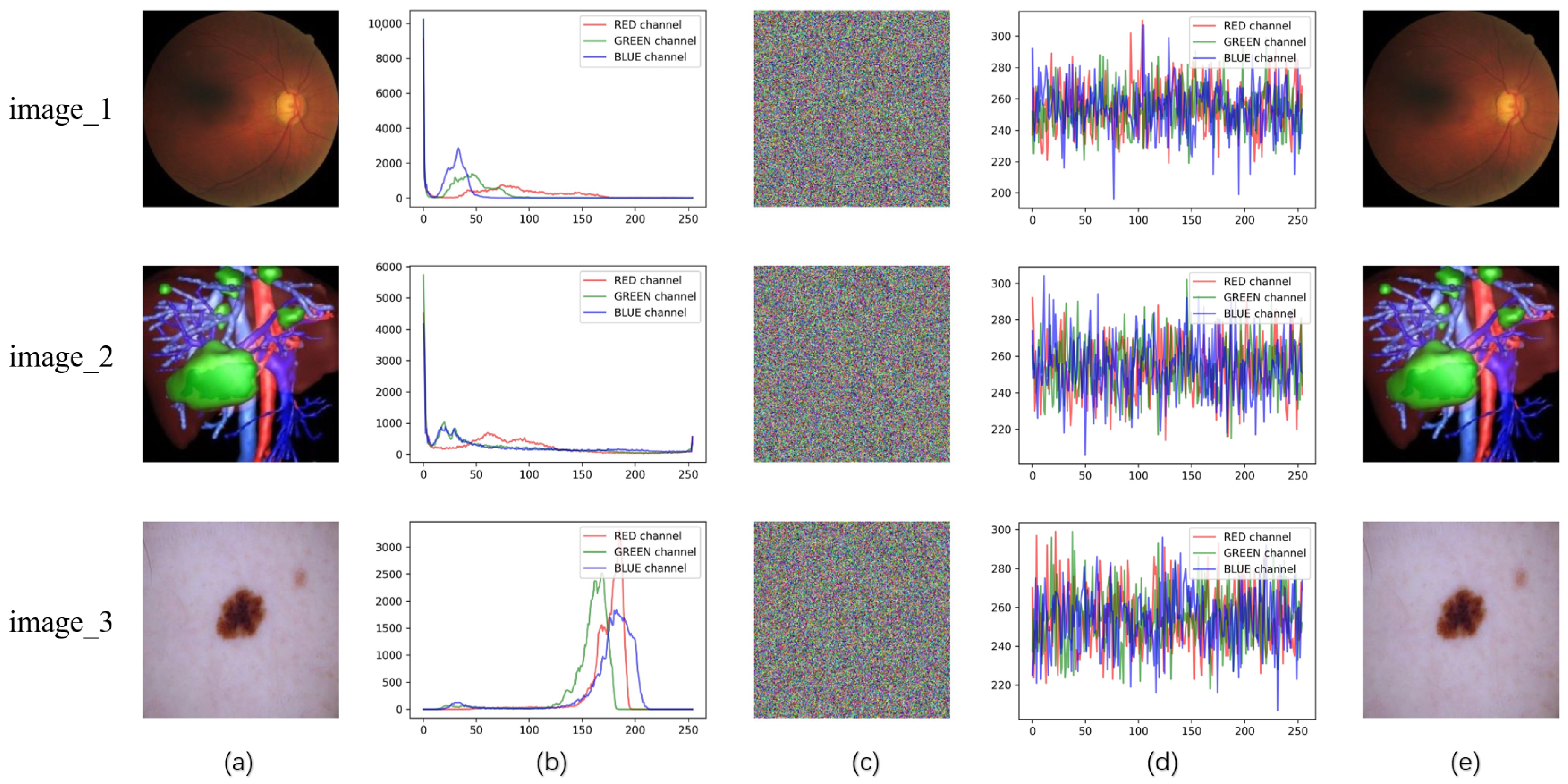
Three images are randomly downloaded from color medical image datasets and preprocessed to a size of 256 × 256 × 3 . The images are named “image_1” [29], “image_2” [30], and “image_3” [31]—with their original sources accessible via the following URLs: “image_1” from the Glaucoma Dataset (https://doi.org/10.1145/3603765.3603779 (accessed on 21 September 2025)), “image_2” from the 3D Medical Image Reconstruction Dataset (https://www.ircad.fr/research/data-sets/ (accessed on 21 September 2025)), and “image_3” from the ISIC 2024 Skin Image Archive (https://www.isic-archive.com/(accessed on 21 September 2025))—as shown in Figure 6a. These images are then processed using ILG-IES with SHA-3-EPFA added. The simulation results of Figure 6c are obtained through encryption, visually obscuring the medical information. The images after direct decryption are shown in Figure 6e, which is not significantly different from the original images. The time cost of the encryption and decryption process is shown in Table 3.

5.2. Key Sensitivity

According to Section 2.2.1, the key is defined as the initial input of the parameters for the 2D Logistic-Gaussian hyperchaotic map. In the improved scheme, the key is represented as K = { x 0 , y 0 , r 0 , A 1 , A 2 } . Given that the key space in this context is 2 256 , the probability of an adversary successfully cracking the key through probabilistic means is exceedingly low.
To analyze the impact of minor changes in the key on the differences between two encrypted images of the same plaintext, we randomly select 1 bit from the key space of K and invert it. This process introduces a slight modification to the key parameters, leading to different chaotic sequences being generated. These modified sequences are then used to encrypt the plaintext image. We conduct 1000 independent experiments, computing the number of pixel change rate (NPCR), uniform average change intensity (UACI), and blocked average changing intensity (BACI) to measure the differences between the resulting pairs of cipher images. The average values of these metrics are presented in Table 4. NPCR, UACI, and BACI are quantitative indicators used to assess the differences between two images, and the calculation formula is shown below.
N P C R ( P 1 , P 2 ) = 1 M N i = 1 M i = 1 N S i g n P 1 ( i , j ) P 2 ( i , j ) × 100 %
U A C I ( P 1 , P 2 ) = 1 M N i = 1 M i = 1 N ( P 1 ( i , j ) P 2 ( i , j ) 255 0 × 100 %
B A C I ( P 1 , P 2 ) = 1 ( M 1 ) ( N 1 ) i = 1 ( M 1 ) ( N 1 ) 1 6 ( d i 1 d i 2 + d i 1 d i 3 + d i 1 d i 4 + d i 2 d i 3 + d i 2 d i 4 + d i 3 d i 4 ) / 255
where
S i g n ( x ) = 1 , x > 0 0 , x = 0 1 , x < 0
D = a b s ( P 1 P 2 ) , D i = d i 1 d i 2 d i 3 d i 4
The calculated average values of NPCR, UACI, and BACI are very close to their theoretical values. This indicates that the differences among the ciphertext images obtained by encrypting “image_1”, “image_2”, and “image_3” with slightly altered keys are significant. Therefore, it can be concluded that each randomly selected key from the key space is effective.

5.3. Plaintext Sensitivity Analysis

Plaintext sensitivity refers to the difference between two ciphertexts obtained by encrypting two plain images with slight differences using the same key. For medical images, certain details such as lesions or abnormal areas may occupy only a small portion of the image. These minor differences are often the critical information in medical images. Therefore, high plaintext sensitivity ensures that these key details are sufficiently obscured during the encryption process, preventing attackers from extracting sensitive data by analyzing local information in the encrypted images.
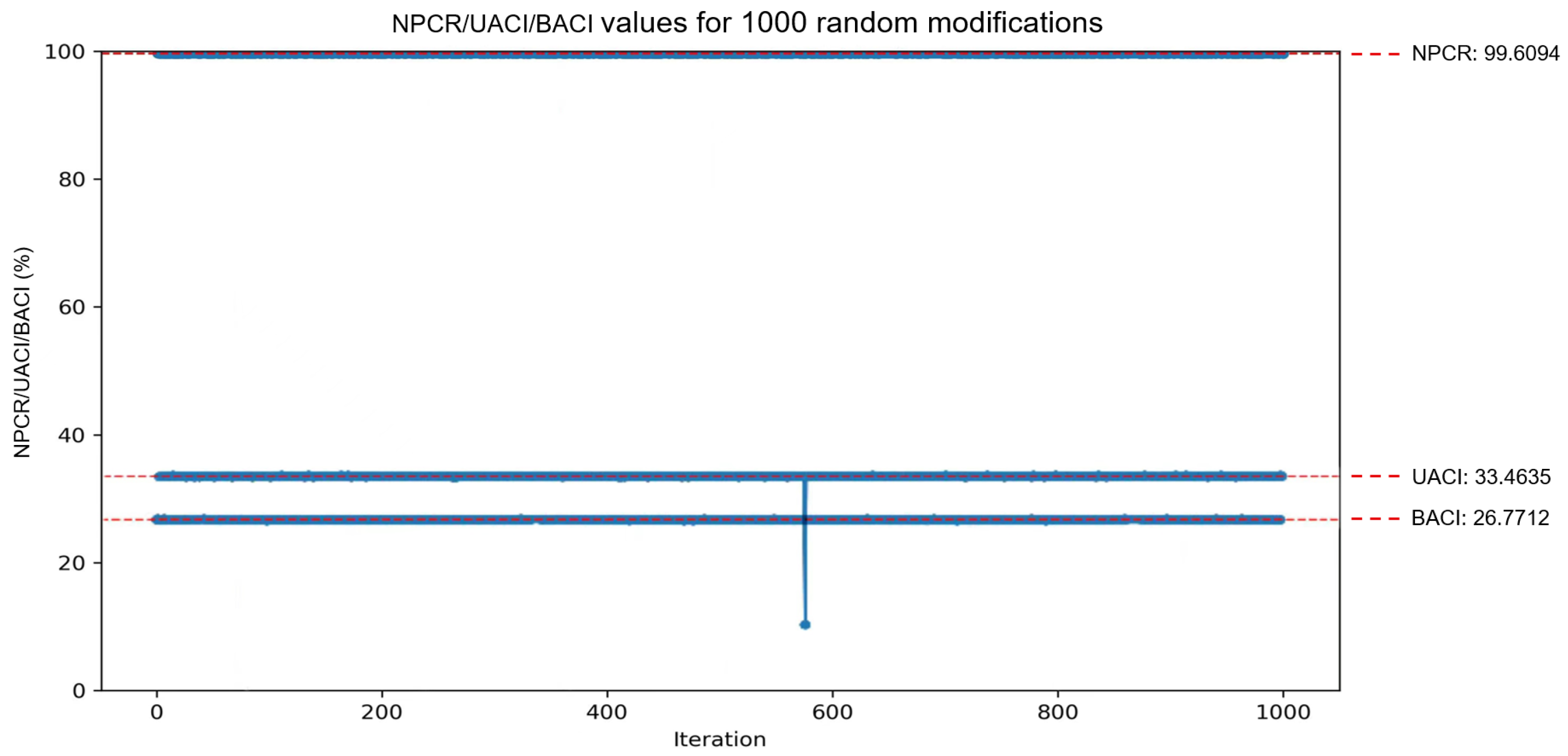
In this analysis, we randomly select an image from “image_1”, “image_2”, and “image_3” and denote it as P. A pixel point ( i , j ) within P is then randomly chosen, and its value is modified to P ( i , j ) m o d 256 , resulting in a slightly adjusted plain image P . This process is repeated 1000 times, encrypting separately. Each time, the NPCR between the cipher images C and C is calculated. The final results of the improved scheme are plotted as shown in Figure 7. where it can be observed that the calculated values closely approach the ideal values ( 99.6094 % , 33.4635 % , 26.7712 % ) . In LG-IES, the average NPCR value obtained was 99.6231 % , whereas in the improved scheme with SHA-3-EPFA added, the NPCR value reached 99.6318 % . This demonstrates that when encrypting with LG-IES enhanced by SHA-3—EPFA, two plaintext images differing by only one bit will produce significantly different ciphertext images. In addition, compared with the original scheme, the algorithm exhibits higher sensitivity to plaintext, possessing excellent differential resistance, which ensures sufficient confidentiality and privacy for color medical images.

5.4. Histogram Analysis

When the histogram of a ciphertext image displays a uniform distribution of pixel values or a high degree of mixing, it indicates that the encryption algorithm possesses enhanced security, making statistical attacks more challenging. As shown in Figure 6, the histograms of each channel in the images encrypted using the improved scheme exhibit a uniform distribution. This demonstrates that the enhanced encryption algorithm effectively conceals the image information.
The χ 2 distribution is defined as follows:
χ 2 = i = 0 255 ( f i g ) 2 g
where g = M N / 256 , f i is the observed pixel proportion of each gray level.
We further compare the balance of the ciphertext histograms between the original and improved schemes. A smaller χ 2 indicates a more balanced histogram, and for grayscale images with a grayscale level of 256, the chi-square is 293 at the common significance level α = 0.05 . Table 5 lists the chi-square results of different channels and the same type of scheme. The chi-square values of the improved scheme are slightly lower than those of the original scheme and are generally below the threshold. This implies that the null hypothesis of histogram uniformity cannot be rejected at a significance level of 0.05. The addition of SHA-3-EPFA encryption results in more balanced histograms.

5.5. Correlation Analysis

Ordinary image pixels are usually highly correlated, and one pixel will often reveal the information of surrounding pixels, which can be used by the opponent to predict the plain image. Therefore, the goal of the encryption algorithm is to reduce this correlation as much as possible. To quantify the linear correlation between pixels, Pearson correlation coefficients [36] are calculated using 5000 randomly selected pixels from each channel. The equation for correlation is as follows:
r x y = cov ( x , y ) D ( x ) D ( y )
where
E ( x ) = 1 N i = 1 N x i
D ( x ) = 1 N i = 1 N x i E ( x ) 2
cov ( x , y ) = 1 N i = 1 N x i E ( x ) y i E ( y )
x i and y i denote the gray value of the pixel pair, N = 5000 is the number of selected pixel pairs.
Figure 8a–c present scatter plots of the three plain images in horizontal, vertical, and diagonal directions, while Figure 8d–f illustrate the correlation in their corresponding encrypted images. Table 6 is the correlation calculation result of “image_1”, where H, V, and D represent horizontal, vertical, and diagonal directions, respectively. In the ciphertext image, the adjacent pixels in various directions are dispersed across the matrix area, with their correlation approaching 0 and outperforming the original scheme. This indicates that the proposed cryptosystem can effectively remove the strong correlation between adjacent pixels of the plain image.

5.6. Entropy Analysis

The information entropy of an image reflects the uncertainty of the image information, and the calculation formula is as follows:
H = i = 0 L p ( i ) log 2 p ( i )
where L is the number of grayscale levels of the image, and p ( i ) represents the probability of occurrence of grayscale value i.
Calculate the gray entropy of the plaintext “image_1”, “image_2”, “image_3” and the cipher images before and after the improved cryptosystem. The results are shown in Table 7. The entropy value of the encrypted images is very close to the entropy value of a randomly generated color image of the same size, which is measured to be 7.62825 . The improved encryption scheme can make the information entropy of the image close to the ideal value; therefore, the algorithm maintains high security and confidentiality.

5.7. Noise and Cropping Attacks

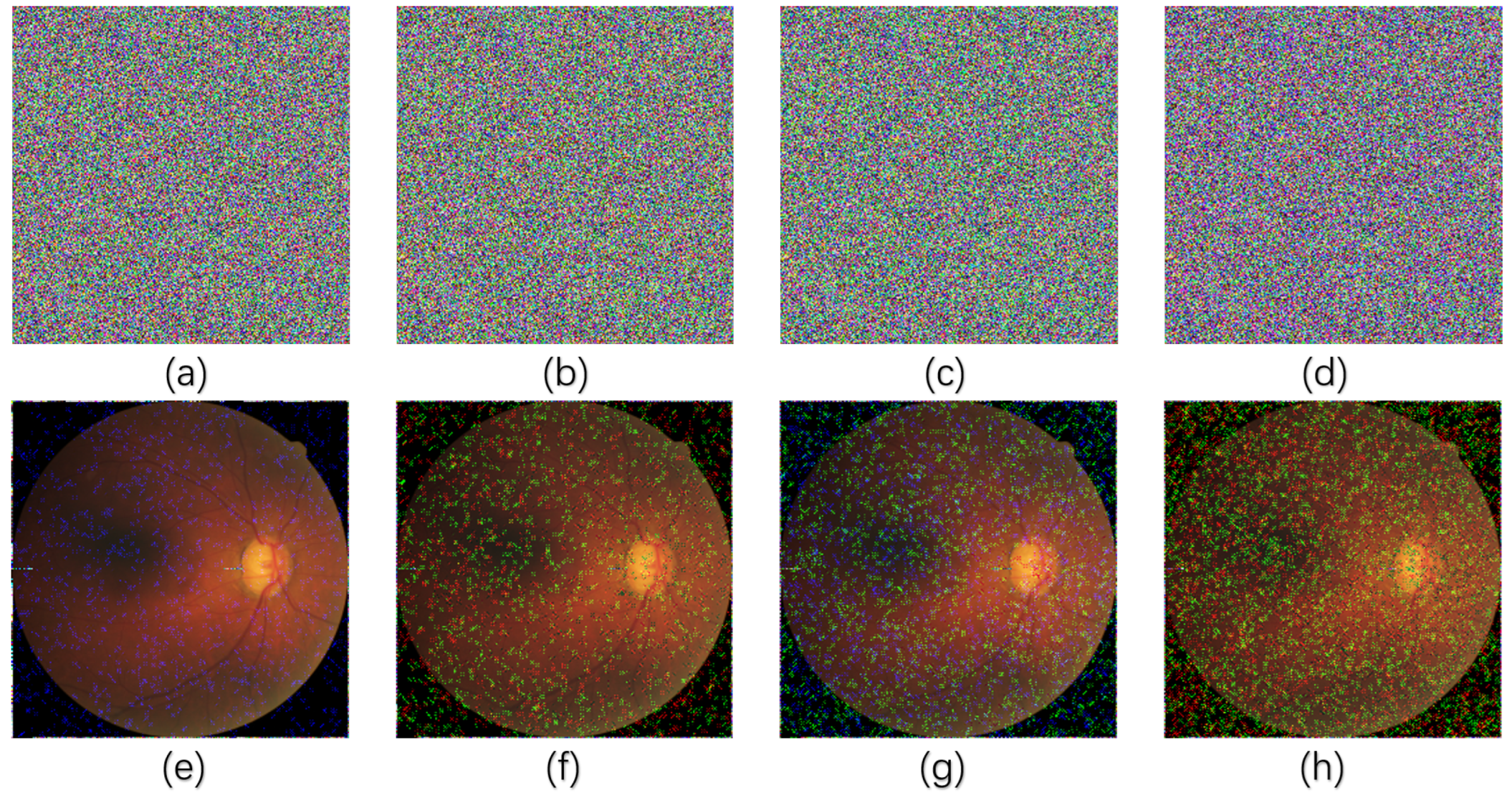
Color medical images often contain important diagnostic information, such as the color and edge details of the lesion. The addition of noise may interfere with these details and thus affect the doctor’s diagnosis. If the encryption algorithm cannot maintain the key features of the decrypted image under noise attack, the application of the algorithm in the medical field may not be robust enough. The experiment introduces 1%, 3%, 5%, and 10% salt and pepper noise to the encrypted “image_1”, creating noisy versions as illustrated in Figure 9a–d. These noisy images are then decrypted, producing four corresponding distorted images shown in Figure 9e–h.
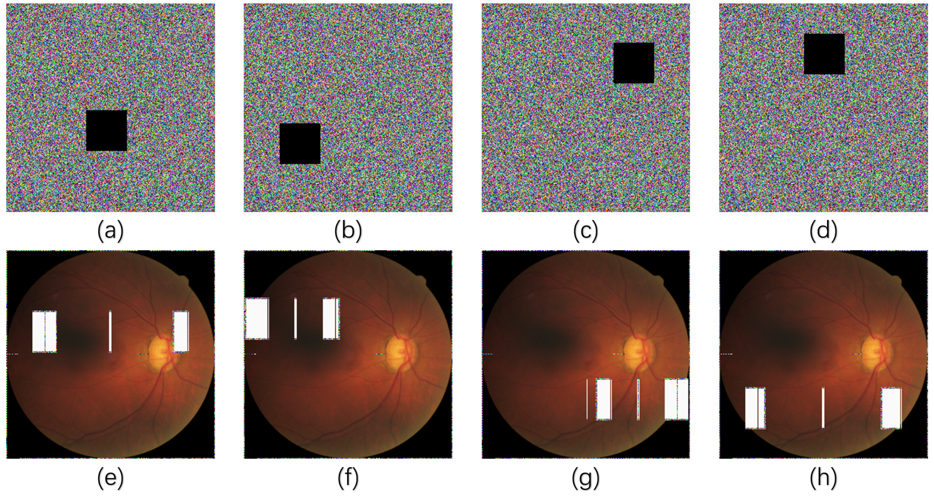
Cropping attacks destroy parts of these areas, causing the decrypted image to lose important information. Evaluating the performance of the encryption algorithm under cropping attacks can ensure that even if part of the image information is lost, as much diagnostic information as possible is retained after decryption, or the missing part of the information is clearly marked. The experiment randomly selects any 100 × 100 positions of the encrypted “image_1” for cropping attacks, as shown in Figure 10a–d, and decrypts them to obtain the distorted images as shown in Figure 10e–h.
Apparently, after noise and cropping attacks, despite some loss of information or anomalies, the scheme can still decrypt the cryptographic images affected by partial (important) data destruction into globally visible images. Color images show better robustness when subjected to external interference, and can well prevent critical medical information from being recovered and leaked by unauthorized visitors.

5.8. Attacks Resistance Analysis

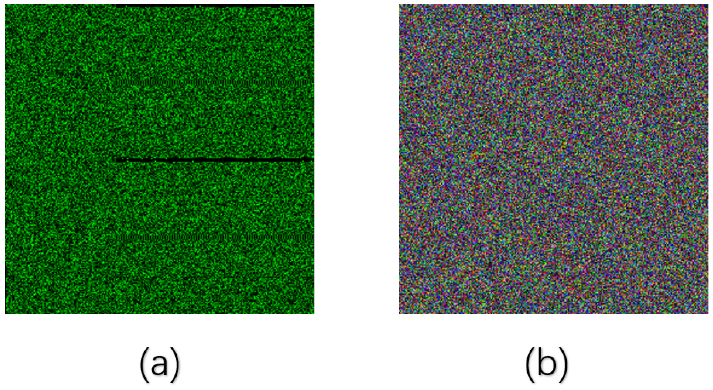
To evaluate the security of the proposed scheme, the same CPA and differential analysis methods as the original scheme were employed. We constructed two specific images: an all-zero image and an image where only one pixel is set to 1 while all others are set to 0. These images were encrypted separately, and then the difference between them was calculated. Figure 11a shows the difference image obtained using the original scheme, while Figure 11b shows the difference image obtained using our scheme. Our scheme not only overcomes the occurrence of a large number of zero pixels at the edges, eliminating discernible patterns, but also further achieves inter-channel fusion, thereby increasing the ciphertext complexity. Based on this, the complexity of attacks on the cipher image is 2 1572864 , equivalent to a brute-force attack. Thus, it can effectively resist the attacks proposed in the cryptanalysis of this paper. Table 8 compares the resistance of the proposed scheme and other schemes to various attacks. It can be seen that SHA-3-EPFA can resist a variety of attacks and has good robustness in the same type of advanced schemes.

6. Conclusions

In this paper, a chaotic image cipher based on algebraic operations is analyzed. We prove that there are some vulnerabilities in this cryptosystem, and we can partially crack the chaotic matrices by constructing special images and establishing linear equations to reduce the secret key space. In addition, in view of the reversibility of the permutation process and the edge correlation and linear features of diffusion, we also propose a three-dimensional image rotation based on SHA-3 that implements an edge-pixel filling algorithm. The experimental results and security analysis show that the improved cryptosystem has good robustness and security while resisting the chosen-plaintext attack.
The proposed SHA-3-EPFA not only enhances the security performance of the original scheme, resisting CPA, KPA, and DC attacks, but it can also be embedded as an independent module into most permutation-diffusion-based encryption models for pixel position perturbation in future work. This is particularly effective for multi-channel images, such as color images, breaking the limitation of traditional encryption methods that only confuse pixels within individual channels. It enables pixel interaction between channels, allowing the encryption algorithm to achieve overall integrity and transferability with relatively low computational overhead.

Author Contributions

Conceptualization, data curation, formal analysis, funding acquisition, resources, software, and supervision were carried out by W.W., while S.W. focused on investigation, methodology, project administration, validation, visualization, and writing the original draft. Both authors collaboratively reviewed, edited, and approved the final manuscript. This research did not receive any specific grant from funding agencies in the public, commercial, or not-for-profit sectors. During the preparation of this work, the authors used artificial intelligence (AI) and AI-assisted technologies in order to enhance the readability and language quality of the text. After using this tool/service, the authors reviewed and edited the content as needed and take full responsibility for the content of the published article. All authors have read and agreed to the published version of the manuscript.

Funding

This research received no external funding.

Data Availability Statement

The data presented in this study are openly available from these sources: One is from the Glaucoma Dataset (https://doi.org/10.1145/3603765.3603779, accessed on 21 September 2025). Another is from the 3D Medical Image Reconstruction Dataset (https://www.ircad.fr/research/data-sets/, accessed on 21 September 2025). The third is from the ISIC 2024 Skin Image Archive (https://www.isic-archive.com/, accessed on 21 September 2025). The fourth is from Chest X-ray Pneumonia Dataset (https://www.kaggle.com/datasets/paultimothymooney/chest-xray-pneumonia, accessed on 21 September 2025).

Conflicts of Interest

The authors declare no conflicts of interest.

Appendix A. Specific Multi-Directional Diffusion Demonstration

In this appendix, we present a table demonstrating the specific multi-directional diffusion coefficients measured in our experiment.
Table A1. Specific multi-directional diffusion demonstration.
EquationT Δ Q 1 Δ Q 2 Δ C
(7) 1 0 0 0 M × N 1 0 0 M × N 0 0 1 M × N 1 1 M × N
(8) 0 1 0 0 0 0 0 0 0 M × N 0 1 0 0 1 2 0 1 M × N 1 0 2 1 0 0 1 0 M × N 2 0 2 0 M × N
(9) 0 1 0 0 M × N 1 1 0 M × N 0 1 1 M × N 1 2 M × N
(10) 0 0 0 1 0 0 M × N 0 0 1 2 0 M × N 0 2 1 0 0 M × N 0 3 0 M × N
(11) 0 0 0 0 0 0 0 0 1 M × N 0 0 1 0 0 1 1 1 3 M × N 3 1 1 1 0 0 1 0 0 M × N 5 1 1 1 7 1 M × N
(12) 0 0 1 0 M × N 1 0 1 M × N 1 0 1 M × N 2 1 M × N
(13) 0 0 0 0 1 0 M × N 0 1 0 0 2 M × N 2 0 0 1 0 M × N 3 0 0 M × N
(14) 0 0 0 1 0 0 0 0 0 M × N 0 0 0 1 1 1 0 2 M × N 2 0 1 1 1 0 0 0 M × N 2 0 2 0 M × N
(15) 0 0 0 0 1 0 0 0 0 M × N 0 0 0 0 1 1 0 1 M × N 1 0 1 1 0 0 0 0 M × N 1 0 1 0 M × N
Note: Red-colored values in the matrices indicate key focused values in cryptanalysis; ∗ represents the calculated unknown pixel value.

Appendix B. Intermediate Ciphertext Representation of Example 2
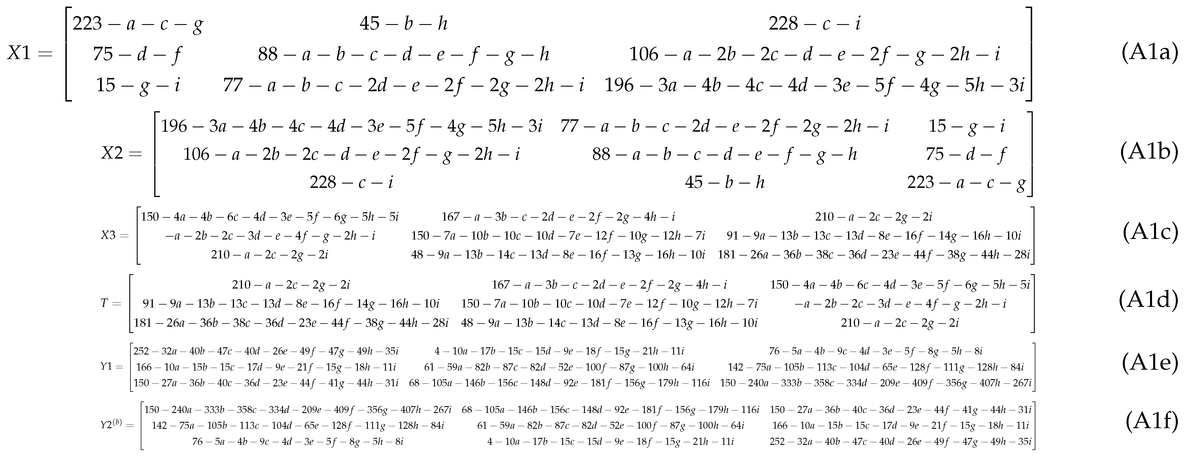
In this appendix, we give some matrices calculated during the encryption process.
Figure A1. Matrices X 1 , X 2 , X 3 , T, Y 1 and Y 2 showing intermediate transformations of Example 2.
Electronics 14 04283 g0a1

References

  1. Zinger, S.; Ruijters, D.; Do, L.; de With, P.H. View interpolation for medical images on autostereoscopic displays. IEEE Trans. Circuits Syst. Video Technol. 2011, 22, 128–137. [Google Scholar] [CrossRef]
  2. Liu, H.; Teng, L.; Zhang, Y.; Si, R.; Liu, P. Mutil-medical image encryption by a new spatiotemporal chaos model and DNA new computing for information security. Expert Syst. Appl. 2024, 235, 121090. [Google Scholar] [CrossRef]
  3. Kaissis, G.A.; Makowski, M.R.; Rückert, D.; Braren, R.F. Secure, privacy-preserving and federated machine learning in medical imaging. Nat. Mach. Intell. 2020, 2, 305–311. [Google Scholar] [CrossRef]
  4. Kaissis, G.; Ziller, A.; Passerat-Palmbach, J.; Ryffel, T.; Usynin, D.; Trask, A.; Lima, I., Jr.; Mancuso, J.; Jungmann, F.; Steinborn, M.M.; et al. End-to-end privacy preserving deep learning on multi-institutional medical imaging. Nat. Mach. Intell. 2021, 3, 473–484. [Google Scholar] [CrossRef]
  5. Ziller, A.; Mueller, T.T.; Stieger, S.; Feiner, L.F.; Brandt, J.; Braren, R.; Rueckert, D.; Kaissis, G. Reconciling privacy and accuracy in AI for medical imaging. Nat. Mach. Intell. 2024, 6, 764–774. [Google Scholar] [CrossRef]
  6. Data Encryption Standard. Data Encryption standard. Fed. Inf. Process. Stand. Publ. 1999, 112, 3. [Google Scholar]
  7. Paar, C.; Pelzl, J.; Paar, C.; Pelzl, J. The advanced encryption standard (AES). Understanding Cryptography: A Textbook for Students and Practitioners; Springer: Berlin/Heidelberg, Germany, 2010; pp. 87–121. [Google Scholar]
  8. Wang, X.; Zhao, M. An image encryption algorithm based on hyperchaotic system and DNA coding. Opt. Laser Technol. 2021, 143, 107316. [Google Scholar] [CrossRef]
  9. Yildirim, M. Optical color image encryption scheme with a novel DNA encoding algorithm based on a chaotic circuit. Chaos Solitons Fractals 2022, 155, 111631. [Google Scholar] [CrossRef]
  10. Wang, X.; Liu, C.; Jiang, D. A novel triple-image encryption and hiding algorithm based on chaos, compressive sensing and 3D DCT. Inf. Sci. 2021, 574, 505–527. [Google Scholar] [CrossRef]
  11. Wang, C.; Song, L. An image encryption scheme based on chaotic system and compressed sensing for multiple application scenarios. Inf. Sci. 2023, 642, 119166. [Google Scholar] [CrossRef]
  12. Brahim, A.H.; Pacha, A.A.; Said, N.H. Image encryption based on compressive sensing and chaos systems. Opt. Laser Technol. 2020, 132, 106489. [Google Scholar] [CrossRef]
  13. Teh, J.S.; Alawida, M.; Sii, Y.C. Implementation and practical problems of chaos-based cryptography revisited. J. Inf. Secur. Appl. 2020, 50, 102421. [Google Scholar] [CrossRef]
  14. Upadhyay, D.; Gaikwad, N.; Zaman, M.; Sampalli, S. Investigating the avalanche effect of various cryptographically secure Hash functions and Hash-based applications. IEEE Access 2022, 10, 112472–112486. [Google Scholar] [CrossRef]
  15. Yuan, F.; Deng, Y.; Li, Y.; Chen, G. A cascading method for constructing new discrete chaotic systems with better randomness. Chaos Interdiscip. J. Nonlinear Sci. 2019, 29, 053120. [Google Scholar] [CrossRef]
  16. Hamza, R.; Yan, Z.; Muhammad, K.; Bellavista, P.; Titouna, F. A privacy-preserving cryptosystem for IoT E-healthcare. Inf. Sci. 2020, 527, 493–510. [Google Scholar] [CrossRef]
  17. Mehdi, S.A.; Ali, Z.L. Image encryption algorithm based on a novel six-dimensional hyper-chaotic system. Al-Mustansiriyah J. Sci. 2020, 31, 54–63. [Google Scholar] [CrossRef]
  18. Liu, X.l.; Xu, K.s.; Kang, Z.c.; Xu, M.t.; Wang, M.m. New 2D inserting-log-logistic-sine chaotic map with applications in highly robust image encryption algorithm. Nonlinear Dyn. 2025, 113, 17227–17256. [Google Scholar] [CrossRef]
  19. Masood, F.; Boulila, W.; Alsaeedi, A.; Khan, J.S.; Ahmad, J.; Khan, M.A.; Rehman, S.U. A novel image encryption scheme based on Arnold cat map, Newton-Leipnik system and Logistic Gaussian map. Multimed. Tools Appl. 2022, 81, 30931–30959. [Google Scholar] [CrossRef]
  20. Chen, J.x.; Zhu, Z.l.; Fu, C.; Zhang, L.b.; Zhang, Y. An efficient image encryption scheme using lookup table-based confusion and diffusion. Nonlinear Dyn. 2015, 81, 1151–1166. [Google Scholar] [CrossRef]
  21. Grošek, O.; Sỳs, M. Isotopy of Latin squares in cryptography. Tatra Mt. Math. Publ. 2010, 45, 27–36. [Google Scholar] [CrossRef]
  22. Hu, G.; Xiao, D.; Wang, Y.; Li, X. Cryptanalysis of a chaotic image cipher using Latin square-based confusion and diffusion. Nonlinear Dyn. 2017, 88, 1305–1316. [Google Scholar] [CrossRef]
  23. Li, M.; Lu, D.; Xiang, Y.; Zhang, Y.; Ren, H. Cryptanalysis and improvement in a chaotic image cipher using two-round permutation and diffusion. Nonlinear Dyn. 2019, 96, 31–47. [Google Scholar] [CrossRef]
  24. Wu, W.; Wang, Q. Cryptanalysis and improvement of an image encryption algorithm based on chaotic and Latin square. Nonlinear Dyn. 2023, 111, 3831–3850. [Google Scholar] [CrossRef]
  25. Chen, Y.; Tang, C.; Ye, R. Cryptanalysis and improvement of medical image encryption using high-speed scrambling and pixel adaptive diffusion. Signal Process. 2020, 167, 107286. [Google Scholar] [CrossRef]
  26. Gaur, K.S.; Singh, H.; Thakran, S. Cryptanalysis of the optical cryptosystem titled “an asymmetric image encryption based on phase truncated hybrid transform”. J. Opt. 2024, 53, 605–609. [Google Scholar] [CrossRef]
  27. Lai, Q.; Hu, G.; Erkan, U.; Toktas, A. High-efficiency medical image encryption method based on 2D Logistic-Gaussian hyperchaotic map. Appl. Math. Comput. 2023, 442, 127738. [Google Scholar] [CrossRef]
  28. Shannon, C.E. Communication theory of secrecy systems. Bell Syst. Tech. J. 1949, 28, 656–715. [Google Scholar] [CrossRef]
  29. Kiefer, R.; Abid, M.; Steen, J.; Ardali, M.R.; Amjadian, E. A Catalog of Public Glaucoma Datasets for Machine Learning Applications: A detailed description and analysis of public glaucoma datasets available to machine learning engineers tackling glaucoma-related problems using retinal fundus images and OCT images. In Proceedings of the 2023 7th International Conference on Information System and Data Mining, Atlanta, GA, USA, 10–12 May 2023; pp. 24–31. [Google Scholar]
  30. Soler, L.; Hostettler, A.; Agnus, V.; Charnoz, A.; Fasquel, J.; Moreau, J.; Osswald, A.; Bouhadjar, M.; Marescaux, J. 3D Image Reconstruction for Comparison of Algorithm Database: A Patient Specific Anatomical and Medical Image Database; Technical Report; IRCAD: Strasbourg, France, 2010. [Google Scholar]
  31. International Skin Imaging Collaboration. ISIC Image Archive. 2024. Available online: https://www.isic-archive.com/ (accessed on 23 July 2024).
  32. Feng, W.; Zhang, J. Exploiting robust quadratic polynomial hyperchaotic map and pixel fusion strategy for efficient image encryption. Expert Syst. Appl. 2024, 246, 123190. [Google Scholar] [CrossRef]
  33. Zhang, D.; Chen, L.; Li, T. Hyper-chaotic color image encryption based on 3D orthogonal Latin cubes and RNA diffusion. Multimed. Tools Appl. 2024, 83, 22571–22594. [Google Scholar] [CrossRef]
  34. Mohamed, H.G.; ElKamchouchi, D.H.; Moussa, K.H. A novel color image encryption algorithm based on hyperchaotic maps and mitochondrial DNA sequences. Entropy 2024, 22, 158. [Google Scholar] [CrossRef]
  35. Raghuvanshi, K.K.; Kumar, S.; Kumar, S.; Kumar, S. Image encryption algorithm based on DNA encoding and CNN. Expert Syst. Appl. 2024, 252, 124287. [Google Scholar] [CrossRef]
  36. Cohen, I.; Huang, Y.; Chen, J.; Benesty, J.; Benesty, J.; Chen, J.; Huang, Y.; Cohen, I. Pearson correlation coefficient. In Noise Reduction in Speech Processing; Springer: Berlin/Heidelberg, Germany, 2009; pp. 1–4. [Google Scholar]
  37. Tan, R.C.; Lei, T.; Zhao, Q.M.; Gong, L.H.; Zhou, Z.H. Quantum Color Image Encryption Algorithm Based on A Hyper-Chaotic System and Quantum Fourier Transform. Int. J. Theor. Phys. 2016, 55, 5368–5384. [Google Scholar] [CrossRef]
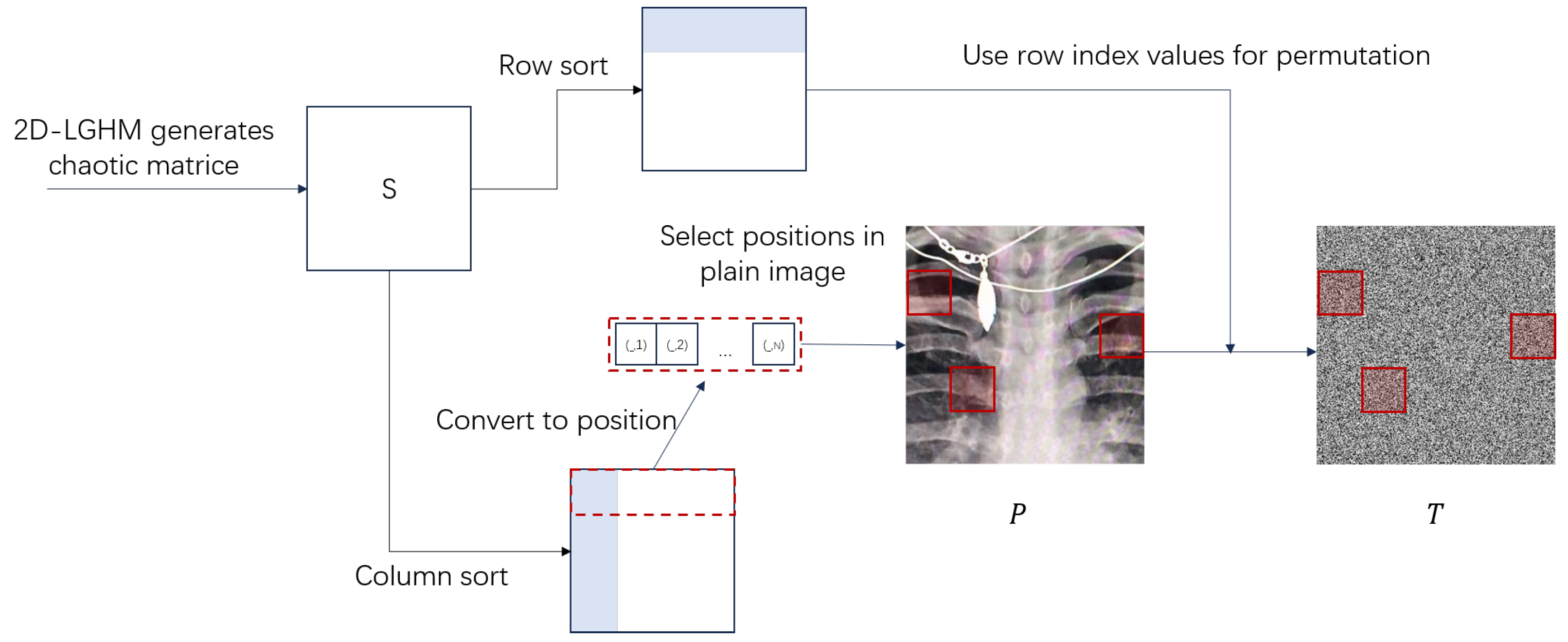
Figure 1. High-efficiency one (Pixel Scrambling Positions Marked by Red Squares) round permutation.
Electronics 14 04283 g001
Figure 2. Multi-directional pixels substitution.
Electronics 14 04283 g002
Figure 3. Block diagram of LG-IES.
Electronics 14 04283 g003
Figure 4. SHA-3-EPFA (Only Key Steps Shown). (a) Divide the rotation area, (b) rotate Rubik’s Cube, and (c) obtain new pixels to fill.
Electronics 14 04283 g004
Figure 5. Block diagram of ILG-IES.
Electronics 14 04283 g005
Figure 6. (a) plain images, (b) histogram of (a), (c) cipher images, (d) histogram of (c), (e) recovered images.
Electronics 14 04283 g006
Figure 7. Plaintext sensitivity analysis.
Electronics 14 04283 g007
Figure 8. Correlation of plain images and cipher images in horizontal, vertical, and diagonal directions, respectively.
Electronics 14 04283 g008
Figure 9. Simulation results of noise attacks. (ad) encrypted “image_1”, respectively, add 1%, 2%, 3%, and 5% of salt and pepper noise; (eh) the corresponding decrypted images.
Electronics 14 04283 g009
Figure 10. Simulation results of cropping attacks. (ad) randomly crop 100 × 100 size of the encrypted “image_1”, (eh) the corresponding decrypted images.
Electronics 14 04283 g010
Figure 11. Contrast resistance attacks.
Electronics 14 04283 g011
Table 1. The proof of Equation (13).
Permuted image Δ T
0 0 0 0 0 0 0 0 0 0 0 0 0 0 0 0 0 0 0 0 0 1 0 0 0
First diffused image Δ Y 1
0 1 0 0 0 0 1 2 2 2 0 1 4 8 12 0 1 6 18 38 0 2 9 33 89
Rotated image Δ Y 2
89 33 9 2 0 38 18 6 1 0 12 8 4 1 0 2 2 2 1 0 0 0 0 1 0
Second diffused image
(Cipher image)
Δ C
89 33 9 3 0 38 178 226 239 242 12 236 132 86 55 2 252 110 73 214 0 254 104 32 63
Note: Red-colored values in the matrices indicate key focused values in cryptanalysis.
Table 2. Reduced Key Space and Time to Solve for Matrix R Across Image Sizes and Types.
Image SizeRank rReduced Key SpaceTime to Solve for R
6 2 96 0.018 s
3 × 3 8 2 32 0.021 s
91 0.024 s
4000 2 3008 0.32 s
64 × 64 4050 2 1408 0.35 s
65,5361 0.41 s
64,000 2 49 , 152 4.2 s
256 × 256 65,000 2 17 , 152 4.8 s
65,5361 5.3 s
Table 3. Time Overhead Comparison Between LG-IES and ILG-IES.
Image SizeScheme TypeTest Medical ImageEncryption/Decryption Time (s)
Encryption Time (s)Decryption Time (s)
256 × 256LG-IESimage_10.38/0.530.42/0.53
image_20.39/0.530.43/0.56
ILG-IESimage_30.38/0.520.41/0.55
256 × 256 × 256LG-IESimage_18.25/9.838.63/11.23
image_28.51/8.548.87/9.87
ILG-IESimage_38.38/8.908.72/9.02
512 × 512 × 512LG-IESimage_118.72/22.1319.35/23.58
image_216.34/17.0515.68/15.98
ILG-IESimage_317.13/18.8916.23/16.52
Table 4. Key sensitivity analysis results.
NPCRUACIBACI
LG-IESILG-IESLG-IESILG-IESLG-IESILG-IES
image_199.674099.611933.458433.565626.796026.8272
image_299.588999.635833.297233.418526.747426.7764
image_399.545399.600233.422233.539226.725426.8079
Ref. [32]99.618933.4707-
Ref. [33]99.851533.5136-
Ref. [34]99.616833.4833-
Ref. [35]99.635033.3100-
Theoretical value99.609433.463526.7712
Note: All values are in percentages (%).
Table 5. Each channel chi-square test for histogram analysis.
RGB
LG-IESILG-IESLG-IESILG-IESLG-IESILG-IES
image_1254.34272.1229.81284.00222.12263,14
image_2274.55255.32274.06238.30251.64242.45
image_3236.32218.99270.45233.89261.43228.01
Ref. [32]275.23
Ref. [33]258.00
Ref. [34]275.00
Ref. [35]250.33
Table 6. Correlation analysis.
Image_1LG-IESILG-IESRef. [32]Ref. [33]Ref. [37]Ref. [35]
RH0.9868−0.00260.00140.00440.0134−0.00180.0012
V0.9747−0.0093−0.0023−0.0022−0.01220.00430.0021
D0.9899−0.02360.00180.0029−0.00090.00070.0015
GH0.9765−0.00270.00160.00270.0100−0.0003−0.0014
V0.9732−0.0052−0.0033−0.0033−0.00020.00130.0015
D0.97870.0169−0.00360.00020.01280.00170.0021
BH0.9848−0.0053−0.00490.00080.0019−0.0023−0.0013
V0.9788−0.0089−0.0018−0.0010−0.0107−0.00040.0003
D0.9821−0.01990.00230.0031−0.0098−0.00100.0017
Table 7. Entropy analysis.
Image_1Image_2Image_3Ref. [32]Ref. [33]Ref. [34]Ref. [37]Ref. [35]
LG-IESILG-IESLG-IESILG-IESLG-IESILG-IES
R7.99737.99757.99697.99697.99717.99727.99717.99717.99707.99597.9896
G7.99717.99737.99717.99767.99707.99737.99727.99707.99787.99517.9996
B7.99697.99767.99807.99747.99707.99687.99727.99707.99877.99577.9996
Table 8. Attacks on various schemes.
Chosen-Plaintext AttackChosen-Ciphertext AttackCiphertext-Only AttackKnown-Plaintext AttackDifferential Attack
SHA-3-EPFA--
Ref. [32]---
Ref. [33]----
Ref. [34]--
Ref. [37]-----
Ref. [35]--
Disclaimer/Publisher’s Note: The statements, opinions and data contained in all publications are solely those of the individual author(s) and contributor(s) and not of MDPI and/or the editor(s). MDPI and/or the editor(s) disclaim responsibility for any injury to people or property resulting from any ideas, methods, instructions or products referred to in the content.