Article

A Rapid and Self-Contained Calibration Method for MIMUs Based on Residual Velocity Measurement

School of Information Science and Technology, Zhejiang Sci-Tech University, Hangzhou 310018, China
*
Author to whom correspondence should be addressed.
Electronics 2025, 14(21), 4277; https://doi.org/10.3390/electronics14214277 (registering DOI)
Submission received: 8 September 2025 / Revised: 17 October 2025 / Accepted: 22 October 2025 / Published: 31 October 2025

Abstract

In micro inertial measurement units (MIMUs), the zero bias, scale factor error, and non-orthogonal error in both gyroscopes and accelerometers will lead to cumulative errors in inertial navigation computation. This paper proposes a rapid, self-contained calibration method for estimating the MIMU output model based on residual velocity measurement, which significantly reduces calibration time and enhances estimation accuracy without requiring high-precision turntables or external references. First, a comprehensive output model of the MIMU is established. Subsequently, a self-contained calibration model based on a Kalman filter is developed, utilizing residual velocity and the difference between gravity-integrated velocity and inertial navigation velocity. Then, an oriented rotation scheme is designed by a self-developed spherical rotation platform, and the observability for parameters in the MIMU output model is analyzed. Finally, the simulation results indicate that the parameters in the MIMU output model can be successfully estimated within 390 s, achieving an estimation accuracy exceeding 85%. The static and dynamic scenario navigation experiment results demonstrate the effectiveness of the proposed self-contained calibration. Collectively, the proposed method provides a rapid, convenient, and self-contained calibration solution for MIMUs.

1. Introduction

The demand for high-precision navigation has significantly promoted the widespread application of micro inertial navigation systems [1,2]. Micro inertial measurement units (MIMUs) have advantages such as low cost, small size, and high precision. Thus, they are utilized in micro inertial navigation systems [3]. However, the zero bias, scale factor error, non-orthogonal error and random errors in the MIMU output model lead to cumulative errors in the navigation calculation for micro inertial navigation systems [4]. Therefore, researchers have focused on the calibration and compensation of MIMUs to increase navigation accuracy [5,6,7,8].
Current methods for calibrating the MIMU parameters can be divided into traditional calibration and systematic calibration methods [9].
For traditional calibration, a turntable is used for multi-position and multi-rotation experiments in the laboratory. Multi-position experiments are used to provide various orientations for the calibration of gyroscopes in the MIMU, while multi-rotation experiments are used to provide different rotation rates for the calibration of accelerometers in the MIMU. This method is time-consuming and requires a high-precision and expensive three-axis turntable [10,11,12]. To overcome these limitations, many researchers have focused on the systematic calibration method, which is also called the system-level calibration method, in-field estimation method, or self-contained method [13,14,15].
Systematic calibration is a self-contained method suitable for in-field applications. Currently, it can be divided into the multi-position fitting method and the Kalman filter-based method. The multi-position fitting method is based on the SINS error equation; the least square method will be used for the calibration to fit the parameters. Zou et al. proposed a robust equipment-free calibration method for low-cost IMUs [16]. Their data collection method is designed to avoid introducing harmful ill-conditioned data for calibration. A multiresolution analysis-based static detector is used to identify subtle IMU motions. Additionally, adjacent static data are used to remove local biases based on outlier-aware optimization. Qureshi et al. presented an approach to calibrate an IMU comprising a MEMS accelerometer and gyroscope [17]. The gravity signal is utilized as a stable reference to perform calibration. Constraints on the sensor’s orientation are eliminated. Then, the IMU is calibrated with just a few simple rotations within 20 min. Zheng et al. designed a two-position continuous calibration scheme to calibrate the IMU [18], requiring 20.5 min to complete the zero bias error calibration. Xu et al. proposed a model-based and efficient parameter correction method for the calibration of the MIMU [19]. The output models of the MIMU are derived from six positions, and a correction method based on this six-position data model is provided. Although the multi-position fitting method can be realized by a low-precision turntable, its accuracy still requires improvement through complex iterative algorithms. Currently, many researchers focus on the calibration of Kalman filter-based methods by optimizing the Kalman filter or improving the calibration path. Ahmed et al. proposed a calibration algorithm using a transformed unscented Kalman filter based on a triangulation algorithm [20]. The parameters of bias, lever arm, scale factor, and misalignment are used to establish the general nonlinear model of the IMU output. This can offer quicker and easier calibration for the parameters of the accelerometer. Bai et al. proposed an optimal path-planning method for IMU calibration based on an improved Dijkstra’s algorithm [21]. The optimal calibration path-planning is modeled as a multi-fork regular root tree model. In addition, a 30-dimensional Kalman filter is designed for calibration. Al Jlailaty et al. proposed a hand calibration method for MIMUs [22]. A special Kalman filter is used, which benefits from zero-velocity measurement updates. The additional constraints on the measurements are used to improve system observability. The experiment shows that the calibration will need 150 s for continuous hand rotation.
According to the above analysis, a primary limitation of traditional calibration is its dependence on the precision of the turntable, which circumvents the need for a turntable but heavily relies on specific rotational excitations. However, not all rotation excitations can guarantee the observability of all parameters; therefore, the calibration accuracy and calibration time remain suboptimal and require further improvement.
Therefore, this paper proposes a rapid and self-contained calibration method for MIMUs that utilizes residual velocity measurement to enhance calibration performance. The main contributions of this work are summarized as follows:
(1)
The Kalman filter based on residual velocity measurement is proposed to estimate the MIMU parameters.
(2)
A specific rotation path is designed to guarantee the observability of all parameters.
The rest of this paper is organized as follows: In Section 2, the calibration model is established for all parameters in the MIMU, and a Kalman filter estimation model based on residual velocity measurement is constructed. Then, an oriented rotation scheme is designed, and the observability for all parameters is analyzed to guarantee the observability of all parameters. In Section 3, simulations and experiments are carried out for the validation of the proposed self-contained calibration method. This work eliminates the need for high-precision turntables or external references, relying solely on inertial measurements themselves, thereby providing a highly practical solution for field applications.

2. Materials and Methods

2.1. Parameters in MIMU Output Model

A typical MIMU comprises a three-axis MEMS accelerometer and a three-axis MEMS gyroscope [23]. The sensitive axes of the three-axis accelerometer and three-axis gyroscope define the accelerometer frame (a-frame) and gyroscope frame (g-frame), respectively. The platform on which the MIMU is mounted defines the platform frame (p-frame). As shown in Figure 1, there may be some deviations between the above three coordinate systems due to the non-orthogonal error.
Using the platform coordinate system as the reference, assume axis xp of p-frame completely overlaps with axis xa of a-frame; then, axis yp will be constrained within zaOya plane. At this moment, the non-orthogonal error of Maxy and Maxz for accelerometers can be considered zero. Given these assumptions, the non-orthogonal error matrices Ma and Mg are denoted by the following:
M a = 0 0 0 M a y x 0 0 M a z x M a z y 0 , M g = 0 M g x y M g x z M g y x 0 M g y z M g z x M g z y 0
where Maij (i = y, z, j = x, y, ij) represents the specific force in i-axis sensed from the output by j-axis accelerometer, and Mgij (i = x, y, z, j = x, y, z, ij) represents the angular velocity in i-axis sensed from the output by j-axis gyroscope.
Then, the outputs of the MIMU in p-frame can be defined as follows:
A p = ( I + δ K a + M a ) A s + B a + V a Ω p = ( I + δ K g + M g ) Ω s + B g + V g
where Ap = [ a x p , a y p , a z p ]T and Ωp = [ ω x p , ω y p , ω z p ]T represent specific force and angular velocity in p-frame, respectively; As = [ax, ay, az]T and Ωs = [ωx, ωy, ωz]T are the outputs of the accelerometer and gyroscope in a-frame and g-frame; δKa = diag(δkax, δkay, δkaz) and δKg = diag(δkgx, δkgy, δkgz) are the scale factor errors; Ba = [bax, bay, baz]T and Bg = [bgx, bgy, bgz]T are the zero bias of the accelerometer and gyroscope; and Va = [vax, vay, vaz]T and Vg = [vgx, vgy, vgz]T are the measurement noise of the accelerometer and gyroscope. Equation (2) can be rewritten as follows:
a x p a y p a z p = 1 + δ k a x 0 0 M a y x 1 + δ k a y 0 M a z x M a z y 1 + δ k a z a x a y a z + b a x b a y b a z + v a x v a y v a z ω x p ω y p ω z p = 1 + δ k g x M g x y M g x z M g y x 1 + δ k g y M g y z M g z x M g z y 1 + δ k g z ω x ω y ω z + b g x b g y b g z + v g x v g y v g z
The parameters of zero bias, scale factor error, and non-orthogonal error for the accelerometer and gyroscope must be calibrated before using the MIMU.

2.2. Parameters’ Estimation by Kalman Filter Based on Residual Velocity Measurement

The self-contained calibration is designed based on the residual velocity measurement taken by the Kalman filter, which is shown in Figure 2.
As shown in Figure 2, the self-contained calibration procedure consists of four steps:
Step 1: Inertial navigation calculation. The raw data from the MIMU are processed through a standard inertial navigation algorithm to obtain the velocity, position, and attitude.
Step 2: Quaternion and direction cosine matrix updating. The quaternion and the direction cosine matrix Cpn will be updated using the angular velocity Ωp and the specific force Ap.
Step 3: Residual velocity calculation. The velocity V1n will be obtained by integrating the specific force An. Simultaneously, the velocity V2n will be derived by integrating the gravitational component. The residual velocity V1nV2n will then be computed, and it will be used as the measurement for the Kalman filter.
Step 4: Parameters’ estimation. The Kalman filter is employed to estimate a 30-dimensional state vector based on the previously obtained residual velocity; this state vector contains 21 parameters targeted for calibration.
As for the Kalman filter, the 30-dimension state vector X for the calibration is defined as follows:
X = [ ϕ T , δ V T , δ P T , B g T , B a T , δ K g , δ K a , M g , M a ] T
where φ = [φe, φn, φu]T represents the misalignment angles between the navigation coordinate system and the platform coordinate system. δV = [δve, δvn, δvu]T and δP = [δL, δλ, δh]T are the velocity errors and position errors in the navigation coordinate system. Bg and Ba are the zero bias vectors of accelerometers and gyroscopes, respectively. δKa = [δkax, δkay, δkaz] and δKg = [δkgx, δkgy, δkgz] are the scale factor errors for accelerometers and gyroscopes. Mg = [Mgxy, Mgxz, Mgyx, Mgyz, Mgzx, Mgzy] and Ma = [Mayx, Mazx, Mazy] are the non-orthogonality errors of the gyroscopes and accelerometers.
At the time k for the estimation of the Kalman filter [24], the state equation can be written as follows:
X k = ϕ k , k 1 X k 1 + Γ k 1 W k 1
where the state transition matrix φk,k−1 can be obtained based on the velocity, attitude, and position error equations [25,26,27]. Γk−1 is the system noise matrix, and Wk−1 is the process noise matrix, satisfying W~N(0, Q), where Q is the process noise variance.
The residual velocity is utilized as the measurement vector Z for the Kalman filter; that is,
Z = δ v e δ v n δ v u T = V 1 n V 2 n
where V1n is the velocity obtained by navigation calculation based on the output specific force of the MIMU, and V2n is the velocity obtained by the integration of the gravitational component. The measurement equation for the Kalman filter [24] at time k is as follows:
Z k = H k X k 1 + V k 1
And the observation matrix H is as follows:
H = 0 3 × 3 I 3 × 3 0 24 × 3
Vk−1 is the measurement noise, satisfying V~N(0, R), where R is the variance in the measurement noise. The measurement noise and the process noise both satisfy the following:
E [ W k ] = 0 , E [ W k W j T ] = Q k δ k j E [ V k ] = 0 , E [ V k V j T ] = R k δ k j , E [ W k V j T ] = 0
where the process noise Wk and the measurement noise Vk are uncorrelated and Gaussian is distributed with zero-mean and covariances Q and R. δ is the Kronecker function. If k = j, then δkj = 1; otherwise, δkj = 0.
When performing Kalman filter estimation, the initial velocities, the initial positions, the initial misalignment angles, the initial matrix of P0, and the matrix of Q and R are set as shown in Table 1.
Based on the Kalman filter estimation algorithm, the calibration for parameters in the MIMU output model will be realized.

2.3. Oriented Rotation for the Self-Contained Calibration

2.3.1. Oriented Rotation Scheme Design

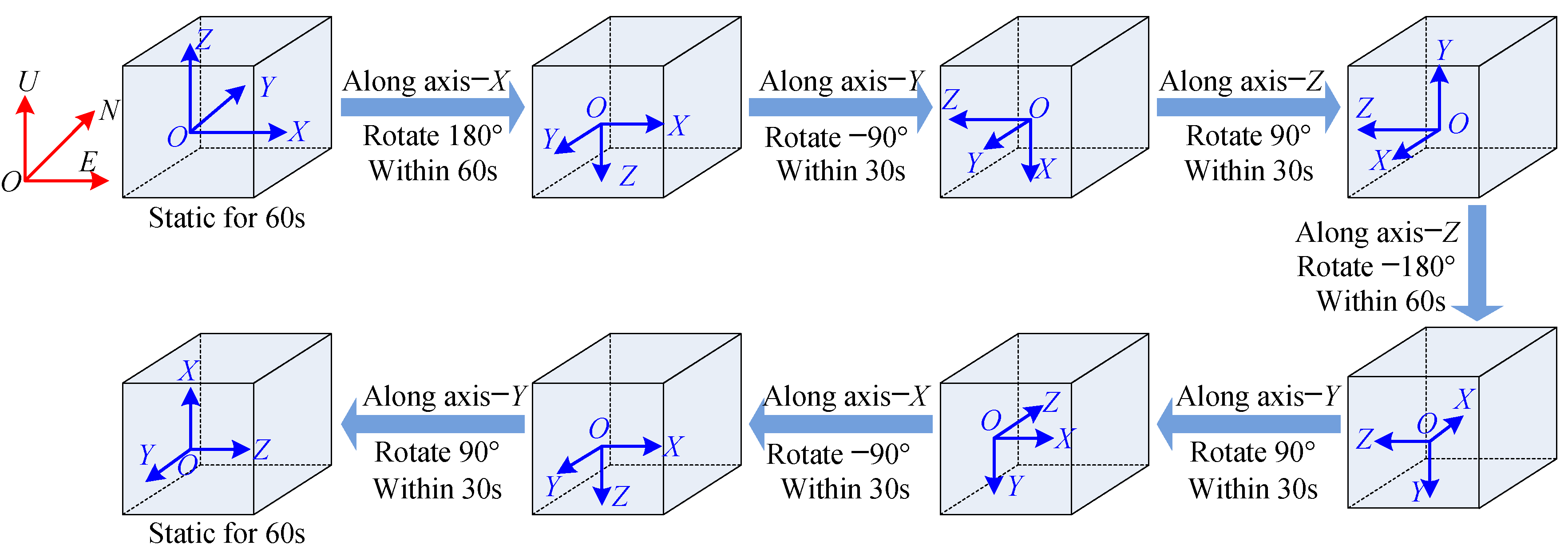
MIMU is installed at the center of the designed spherical rotating platform, as shown in Figure 3. The platform is then rotated through a specific sequence, and the MIMU outputs are recorded for each orientation. The oriented rotation is designed as illustrated in Figure 4.
The oriented rotation steps are set as follows: first, the initial position of the MIMU platform is aligned for East–North–Up (ENU) directions. Remain stationary for 60 s, → rotate along axis-X at 180° for 60 s → rotate along axis-Y at −90° for 30 s → rotate along axis-Z at 90° for 30 s → rotate along axis-Z at −180° for 60 s → rotate along axis-Y at 90° for 30 s → rotate along axis-X at −90° for 30 s → rotate along axis-Y at 90° for 30 s → remain stationary for 60 s. (As for the counterclockwise rotation, the rotation degree is positive. And as for the clockwise rotation, the rotation degree is negative.) The total oriented rotation for the calibration will last for 390 s.

2.3.2. Observability Analysis for Oriented Rotation

The efficiency of the self-contained calibration method can be pre-evaluated by observability analysis [28]. In traditional methods, the observability matrix QSOM is used to determine whether the parameters are observable by calculating the rank of QSOM. But the quantity of the observability for each state variable cannot be obtained. The improved singular value decomposition method [29] will be used for the observability analysis. As for a linear time-invariant system, suppose the initial state vector is X0Rn, and the measurement vector is ZRm; then, the observability matrix from the first to the q-th time interval is as follows:
Q S O M ( q ) = [ Q 1 Q 2 e ϕ 1 Δ 1 Q q e ϕ 1 Δ 1 + ϕ 2 Δ 2 + + ϕ q Δ q ] T
where Δj (j = 1, 2, ⋯, q) denotes the length of the j-th time interval, and then Qj = [(Hj) (Hjϕj)T ⋯ (Hjϕjn−1)]Tmn×n. According to [30], the equation can be simplified to the following:
Q S O M ( q ) = [ Q 1 Q 2 Q q ] T
The relationship between the measurement Zqmn×1 of q time periods and the initial state X0 is as follows:
Z = Q S O M ( q ) X 0
The singular value decomposition can be carried out for the qmn × n-order QSOM(r) by the following:
Q S O M ( q ) = U S V T = U Σ r × r 0 r × ( n r ) 0 ( q m n r ) × r 0 ( q m n r ) × ( n r ) V T
where U = [u1 u2uqmn] and V = [v1 v2vn] are the unit orthogonal matrices of qmn-order and n-order, respectively. Σ = diag[σ1, σ2, …, σr] and σ1σ2 ≥ … ≥ σr are the non-zero singular values. This can be substituted into Equation (11) by the following:
Z = ( U S V T ) X = ( i = 1 n σ i u i v i T ) X
where vi = [v1i, v2i, ⋯ vni]T and U are the unit unitary matrix. UT is multiplied for both sides of the above equation by the following:
U T Z = S V T X 0 = Σ r × r 0 r × ( n r ) 0 ( q m n r ) × r 0 ( q m n r ) × ( n r ) v 1 T v 2 T v n T X 0 = σ 1 ( v 11 x 1 + v 12 x 2 + + v 1 n x n ) σ r ( v r 1 x 1 + v r 2 x 2 + + v r n x n ) 0 ( p m n r ) × 1
where xj (j = 1, 2,⋯, n) is the j-th element of X0. vij(j = 1, 2,⋯, n) is the j-th element of vi.
The observability is determined by the system model, and it is independent of the measurement Z. UTZ is a linear combination of Z, and its observability is determined by the right singular value matrix V and the singular values [31].
Equation (15) shows that σi is related to the linear combination of X0. The larger σi is, the higher the observability of the state variable is. The observability of the state xj is distributed across the singular values, with its weight distribution determined by the j-th element of V. Thus, the observability of the state variable xj is defined by the following [32]:
O j = i = 1 r σ i v i j 2 ,   ( j = 1 , 2 , , n )
With Equation (16) normalized, the observability can be defined by the following:
η j = O j O o   ,   ( j = 1 , 2 , , n )
where Oo is the maximum relative observability. In this paper, this refers to the observability of the residual velocity.
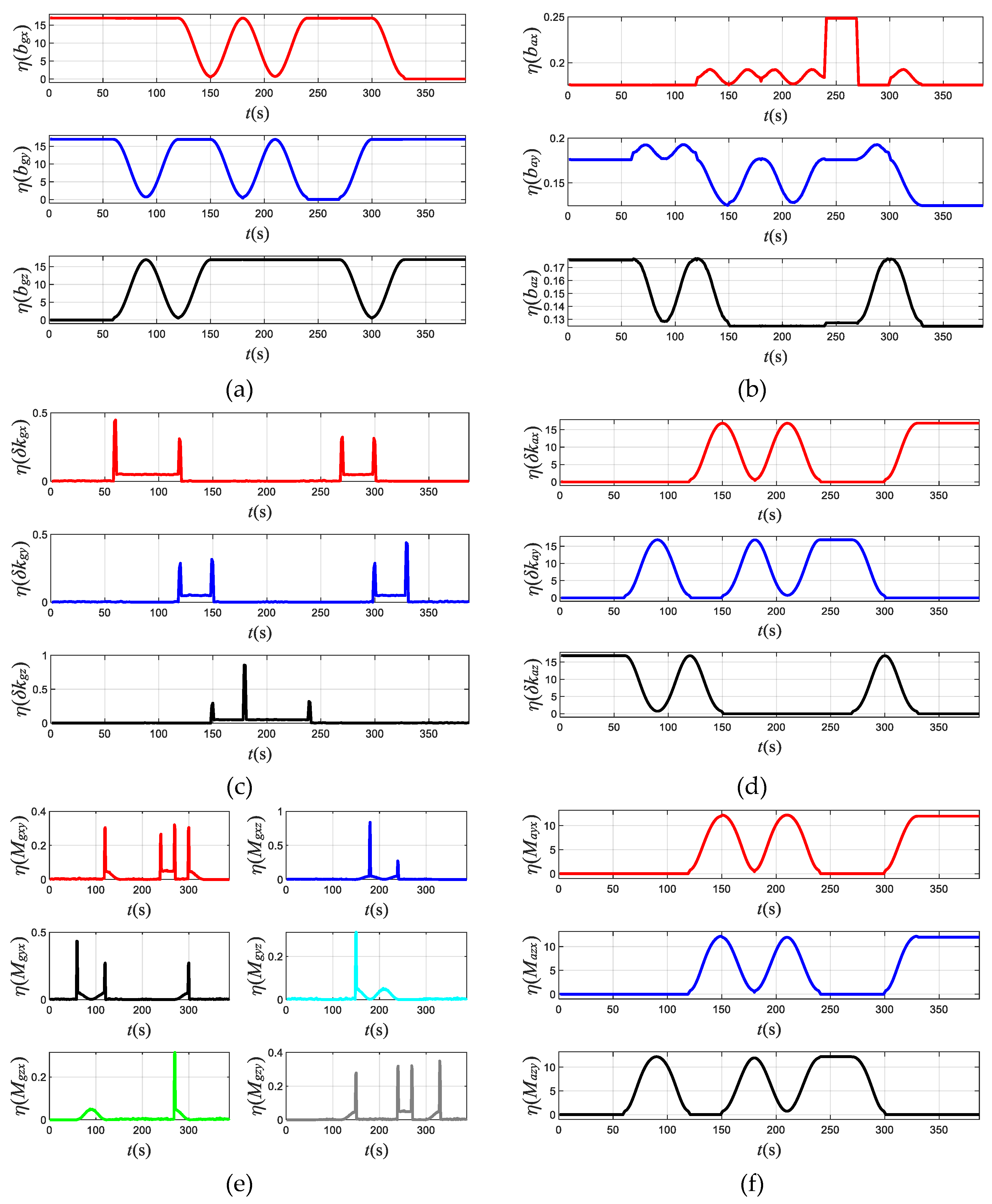
According to the designed oriented rotation, numerical simulation analysis was performed. Suppose that the rotation angular velocity is 9°/s, and the output frequency of the MIMU is 100 Hz. Figure 5 shows the observability analysis of the filter estimation for all parameters under the designed oriented rotation.
Figure 5a shows that as for the initial position within 60 s, the observability of zero bias bgx and bgy for gyroscopes is about 16; thus, they are fully observable. And as for the moment between 150 s and 250 s, the observability of zero bias bgz for gyroscope is about 16; also, in these moments, bgz is fully observable.
Figure 5b shows that as for the moment between 240 s and 270 s, the observability is 0.25 for zero bias bax, and the max observabilities are about 0.18 for zero bias bay and baz; they are basically observable.
Figure 5c shows that the max observability of scale factor errors δkgx, δkgy, and δkgz for gyroscopes is 0.45, 0.44, and 0.86, respectively, and they are basically observable.
Figure 5d shows that the observability of scale factor errors δkax, δkay, and δkaz for accelerometers appears high and low in sequence, and the highest value can reach 16, which indicates that they are fully observable.
Figure 5e shows that the observability of non-orthogonal errors Mgxy, Mgxz, Mgyx, Mgyz, Mgzx, and Mgzy for gyroscopes ranges from 0.3 to 0.8, and it also indicates that they are basically observable.
Figure 5f shows that the observability of non-orthogonal errors Mayx, Mazx, and Mazy for the accelerometer appears high and low in sequence, and the highest value can reach 12, which indicates that they are fully observable.
Based on the rotation scheme designed in Section 2.3, a numerical simulation analysis and experimental tests were conducted to evaluate the self-contained calibration method for parameters in the MIMU output model using residual velocity measurement.

3. Simulation and Experiment Analysis

3.1. Numerical Simulation

In the numerical simulation, the initial parameters for the estimation of the Kalman filter are illustrated in Section 2.2, and the parameters of the MIMU for the simulation are listed in Table 2.
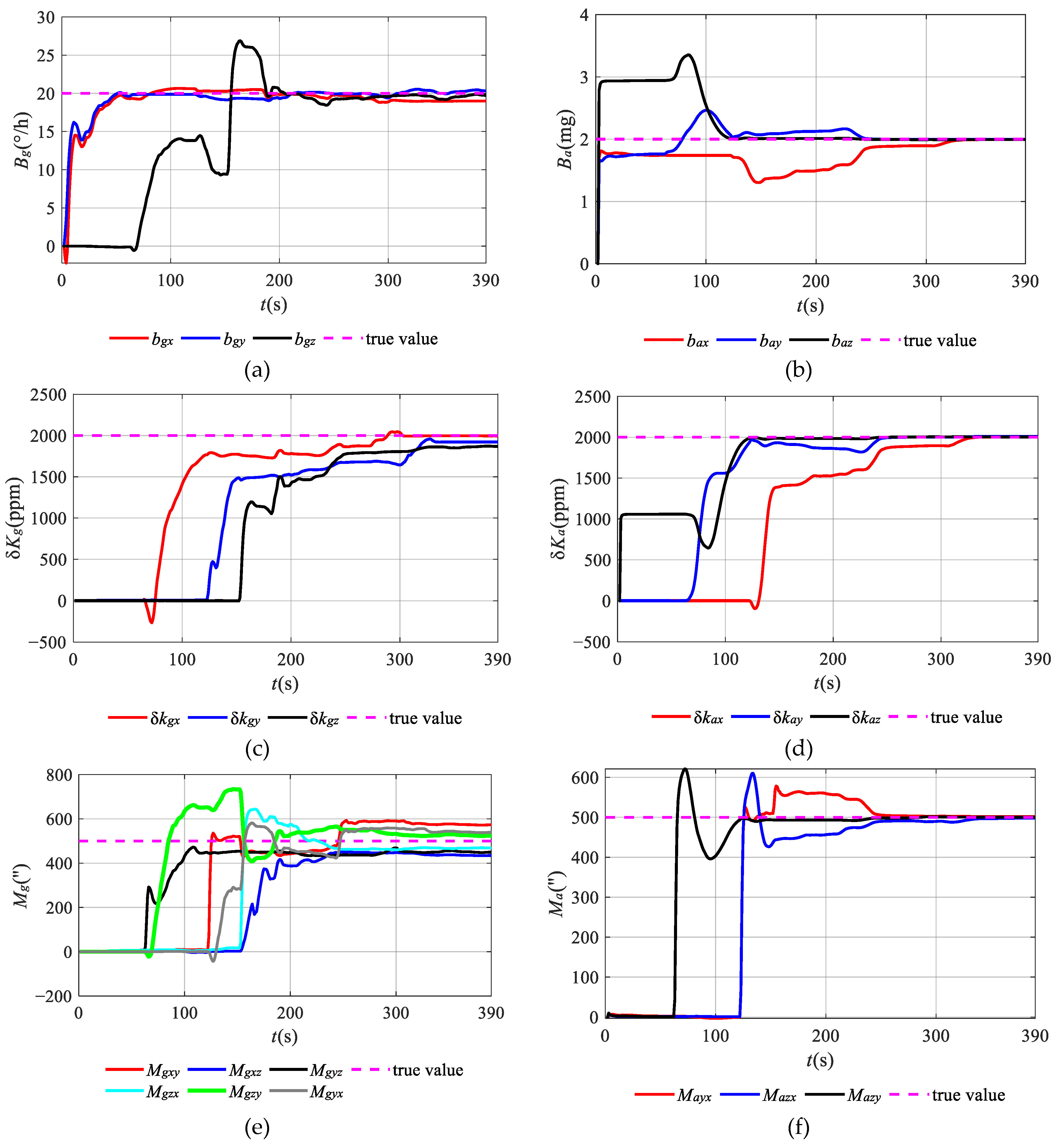
Figure 6 shows the estimation results of parameters in the MIMU during the self-contained calibration based on residual velocity.
Figure 6a shows that after 180 s, the estimated curves of bgx, bgy, and bgz for gyroscopes gradually converge to the set values. Figure 6b shows that the estimated curves of bay and baz for accelerometer firstly converge to the set values, and then the estimated curve of bax converges after 240 s. Since the observability of bax, bay, and baz is relatively low, they need more time for the estimation. Figure 6c shows that the estimated curves of δkgx, δkgy, and δkgz for gyroscopes gradually converge to the set values after 300 s, 330 s, and 240 s, respectively. In Figure 6d, the estimated curves of δkax, δkay, and δkaz for accelerometers gradually converge to the set values after 330 s, 240 s, and 120 s, respectively. As shown in Figure 6e, the estimated curves of Mgxy, Mgxz, Mgyx, Mgyz, Mgzx, and Mgzy for gyroscopes converge to the set values after 300 s, 240 s, 300 s, 240 s, 270 s, and 330 s, respectively. In Figure 6f, the estimated curves of Mayx, Mazx, and Mazy for accelerometers gradually converge to the set values after 330 s, 330 s, and 270 s, respectively. The larger the observability, the less time there is for the estimation of the parameters. The total estimation time is about 390 s.
The estimation curves for the self-contained calibration of the parameters in the MIMU output model are consistent with the observability analysis. Table 3 presents the statistical results for the estimation of the self-contained calibration.
As shown in Table 3, the estimation accuracy for the zero bias and scale factor of the gyroscope is approximately 95%, and the estimation accuracy for that of the accelerometer is approximately 99%. The estimation accuracy for the non-orthogonality error of the gyroscope is greater than 85%, and the estimation accuracy for that of the accelerometer is approximately 99%.
The oriented rotation scheme design uses the residual velocity by dynamic gravitation. And in this condition, the parameters in the MIMU output model for the accelerometer are well observed. Therefore, the estimation accuracy for the parameters of the accelerometer is higher than that of the gyroscope, and this is consistent with the previous observability analysis.

3.2. Experiment Analysis

The designed MIMU consists of a three signal-axis MEMS gyroscope of type ADXRS453 and a three-axis accelerometer of type ADXL343, as shown in Figure 7.
And as for the previous experiment, we have calculated the Allan variance in the used ADXRS453 and ADXL343 from the acquired outputs, as shown in Table 4.
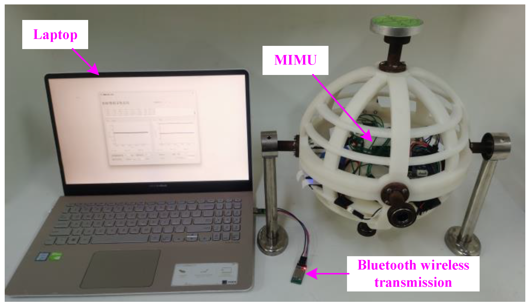
The self-made spherical platform and bracket are shown in Figure 8. The designed MIMU is placed at the center of the spherical platform, and the spherical platform is rotated according to the designed oriented rotation scheme.
According to the self-contained calibration method designed in Section 2, three groups of parameters’ estimation for the MIMU output model were created. Prior to each group, MIMU underwent a 30 min warm-up period to stabilize its output. Data were then collected according to the designed oriented rotation. After each group, a one-hour cooldown interval was maintained to allow the MIMU return to the ambient temperature of 25 °C before starting the next group.
Then, when performing the estimation process of the Kalman filter, matrices Q and R were set as in Table 1. Figure 9 illustrates the estimation results of one group.
Figure 9 shows that the estimation curves of all parameters in the MIMU output model can converge to be a constant value by the designed oriented rotation scheme. In Figure 9a, the estimation curves of bgx and bgy for the gyroscope can rapidly converge within 60 s, and the estimation curve of bgz can converge after 180 s. In Figure 9b, the estimation curves of bay and baz for the accelerometer converge first, while the estimation curve for bax gradually converges after 240 s. In Figure 9c and Figure 9d, the estimated curves of δkgx, δkgy, and δkgz for gyroscopes can gradually converge after 300 s, 330 s, and 240 s, respectively. The estimated curves of δkax, δkay, and δkaz for accelerometers gradually converge after 330 s, 240 s, and 120 s, respectively. In Figure 9e and Figure 9f, the estimated curves of Mgxy, Mgxz, Mgyx, Mgyz, Mgzx, and Mgzy for gyroscopes gradually converge after 300 s, 240 s, 300 s, 240 s, 270 s, and 330 s, respectively. The estimated curves of Mayx, Mazx, and Mazy for accelerometers gradually converge after 330 s, 330 s, and 270 s, respectively. All parameters can be estimated within 390 s. And the experiment results are consistent with the simulation analysis in Section 3.1. Table 5 outlines the statistical results for the parameters’ estimation of three groups of system calibration.
According to the calibration results in Table 4, the mean values are substituted into Equation (3), and the parameters of zero bias, scale factor error, and non-orthogonal error are decoupled for the accelerometer and gyroscope.
To verify the efficiency of the systemic calibration, the static navigation and dynamic scenarios experiment have been implemented according to the output of MIMU before and after decoupling.
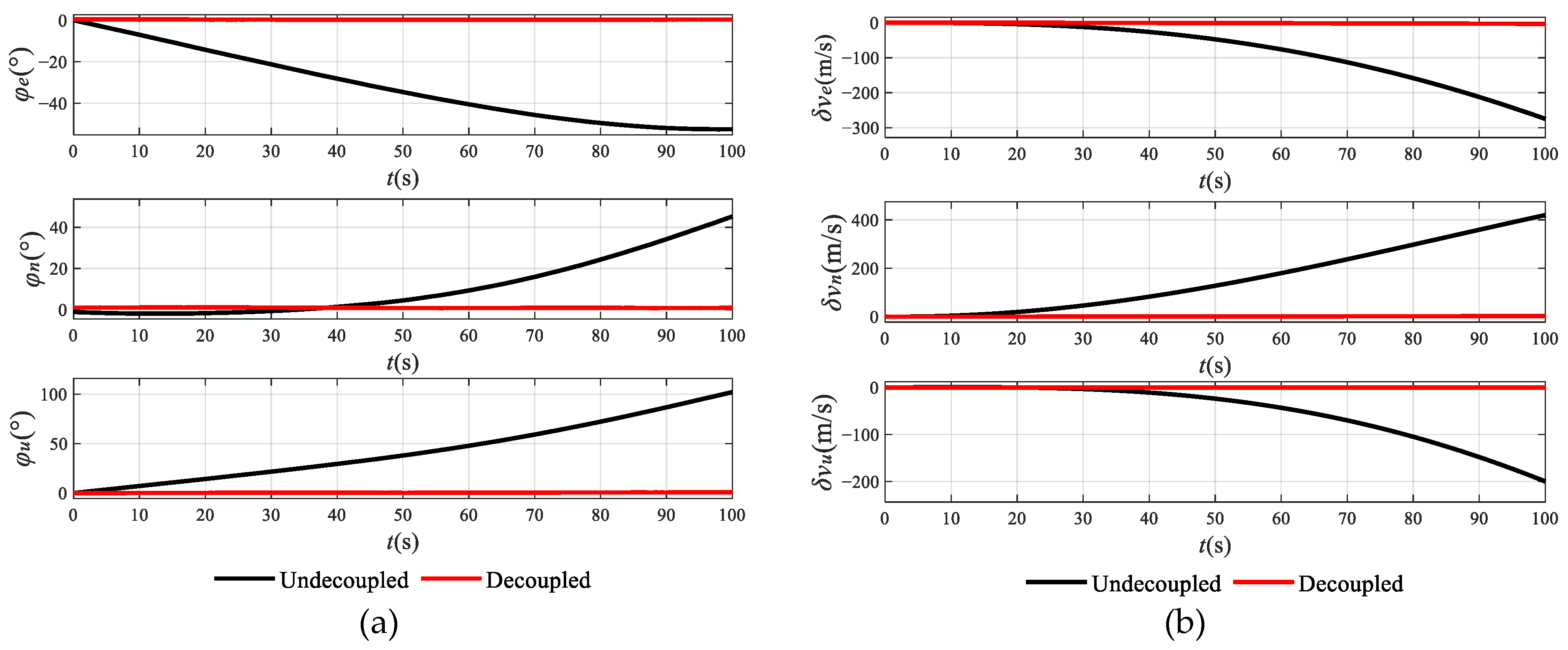
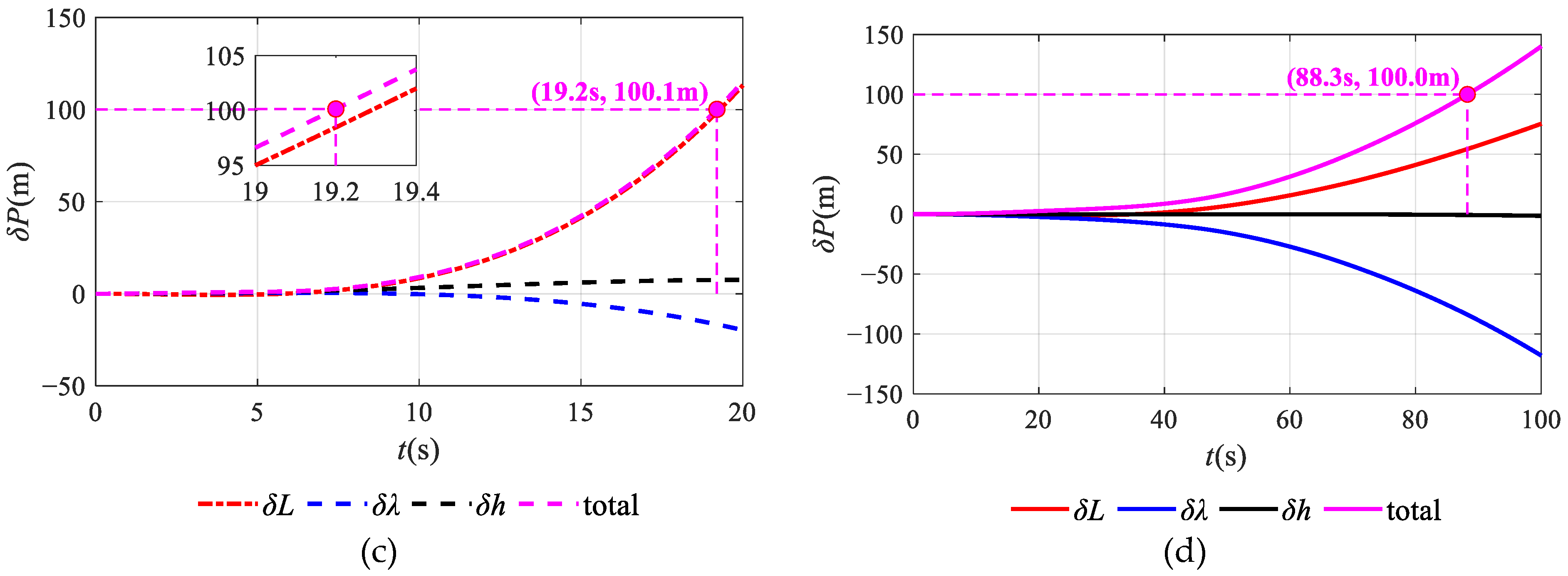
(1) As for the static navigation, Figure 10 shows the static navigation calculation results.
Figure 10 shows that the attitude error, velocity error, and position error are retrained effectively after decoupling in the static navigation calculation. Before decoupling the output of the MIMU, the maintain time is about 19.2 s for the total position error of 100 m; thus, the position drift per unit time is about 5.028 m/s. However, after decoupling the output of the MIMU, the maintain time is about 88.3 s for the total position errors of 100 m; thus, the position drift per unit time is about 1.132 m/s. The relative position drift rate has improved by 78.26%. It has greatly retrained the accumulative error rate of inertial navigation.
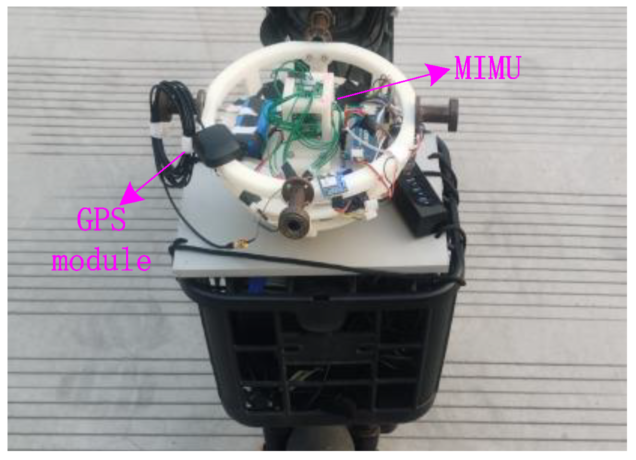
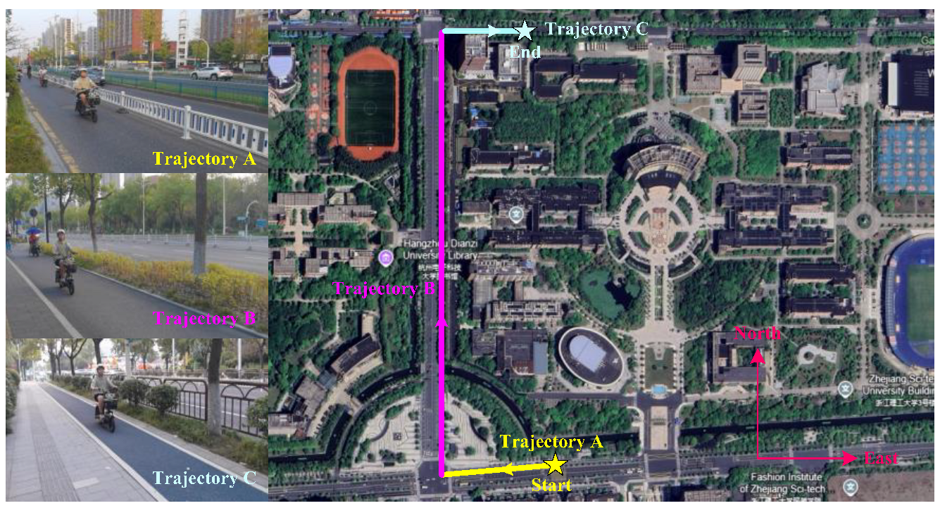
(2) As for the dynamic scenarios experiment, the MIMU is mounted on the front platform of the vehicle, as shown in Figure 11. The vehicle’s trajectory is constrained to the road, as depicted in Figure 12.
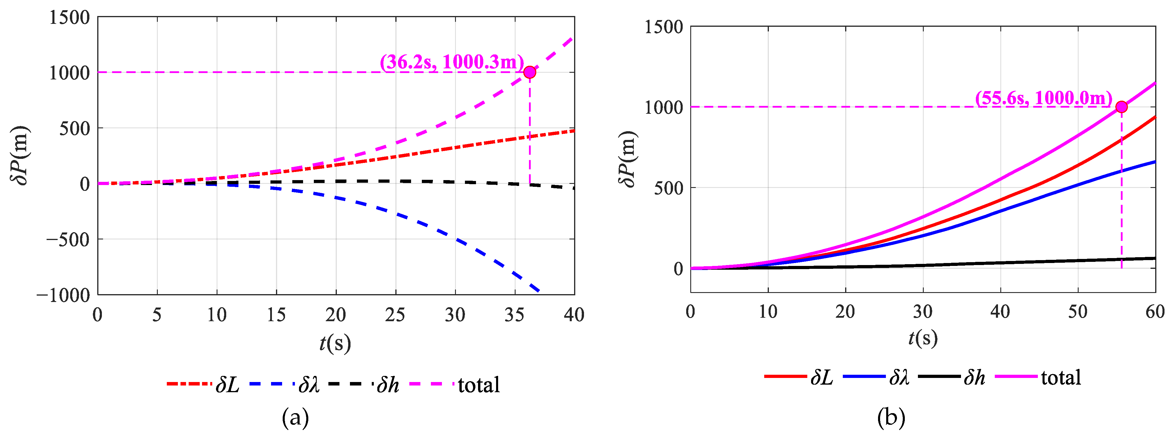
The outputs of the MIMU and GPS are collected. The total position error for the MIMU navigation solution relative to the GPS reference is computed both before and after decoupling, as shown in Figure 13.
In Figure 13, the time required for the total position error to reach 1000 m is about 55.6 s for the MIMU after decoupling, while that for MIMU before decoupling is 36.2 s. It has effectively mitigated the cumulative error, thereby extending the operational duration of inertial navigation systems.
In the aforementioned analysis, the experiment for both static and dynamic scenarios demonstrated the effectiveness of the proposed self-contained calibration method. It can enhance the stability of MIMU for inertial navigation.

4. Conclusions

This research proposes a rapid and self-contained method for calibrating MIMU output model parameters, which utilizes residual velocity measurement and eliminates the need for high-precision turntables. The proposed methodology unfolds in four key stages: (1) establishing a comprehensive output model that includes zero bias, scale factor error, and non-orthogonal error; (2) developing a self-contained calibration model based on the Kalman filter, which utilizes the residual velocity measurement derived from the difference between the velocity obtained by the gravity integration and that from the inertial navigation computation; (3) designing an oriented rotation scheme for self-contained calibration and analyzing the observability of parameters in the MIMU output model by the improved singular value decomposition method; and (4) validating the method through simulations and experiments. The results demonstrate that the proposed approach achieves parameter estimation accuracy exceeding 85% within 390 s. Navigation experiments under both static and dynamic scenarios confirm the practical efficacy of the method. In summary, this work provides a rapid, accurate, and self-contained calibration solution suitable for applications where high-precision external references are unavailable.

Author Contributions

Conceptualization, L.X. and Y.X.; methodology, L.X. and T.Z.; software, L.X.; validation, J.M. and T.Z.; investigation, T.Z.; data curation, T.Z. and J.M.; writing—original draft preparation, Y.X.; writing—review and editing, Y.X.; visualization, L.X.; project administration, Y.X. and J.L.; funding acquisition, Y.X. and J.L. All authors have read and agreed to the published version of the manuscript.

Funding

This research was funded by the National Natural Science Foundation of China (62203393), Natural Science Foundation of Zhejiang Province (LQ20F030019), and Basic Public Welfare Research Program of Zhejiang Province (LGG22E050051).

Data Availability Statement

The data presented in this study are available on request from the authors.

Conflicts of Interest

The authors declare no conflicts of interest.

References

  1. Stefanoni, M.; Kovács, I.; Sarcevic, P.; Odry, Á. A Survey on the Main Techniques Adopted in Indoor and Outdoor Localization. Electronics 2025, 14, 2069. [Google Scholar] [CrossRef]
  2. Zhang, T.; Yuan, M.; Wang, L.; Tang, H.; Niu, X. A robust and efficient IMU array/GNSS data fusion algorithm. IEEE Sens. J. 2024, 24, 26278–26289. [Google Scholar] [CrossRef]
  3. Xie, D.; Jiang, J.; Yan, P.; Wu, J.; Li, Y.; Yu, Z. A Novel Three-Dimensional Positioning Method for Foot-Mounted Pedestrian Navigation System Using Low-Cost Inertial Sensor. Electronics 2023, 12, 845. [Google Scholar] [CrossRef]
  4. Belfadel, D.; Haessig, D. Accelerometer Bias Estimation for Unmanned Aerial Vehicles Using Extended Kalman Filter-Based Vision-Aided Navigation. Electronics 2025, 14, 1074. [Google Scholar] [CrossRef]
  5. Huang, F.; Wang, Z.; Xing, L.; Gao, C. A MEMS IMU gyroscope calibration method based on deep learning. IEEE Trans. Instrum. Meas. 2022, 71, 1003009. [Google Scholar] [CrossRef]
  6. Wang, Z.; Xie, Y.; Yu, X.; Fan, H.; Wei, G.; Wang, L.; Fan, Z.; Wang, G.; Luo, H. A system-level calibration method including temperature-related error coefficients for a strapdown inertial navigation system. Meas. Sci. Technol. 2021, 32, 115117. [Google Scholar] [CrossRef]
  7. Brunson, B.; Wang, J. Analytical framework for online calibration of sensor systematic errors under the generic multisensor integration strategy. Sensors 2025, 25, 3239. [Google Scholar] [CrossRef]
  8. Liu, B.; Wei, S.; Su, G.; Wang, J.; Lu, J. An improved fast self-calibration method for hybrid inertial navigation system under stationary condition. Sensors 2018, 18, 1303. [Google Scholar] [CrossRef]
  9. Xu, B.; Wang, L.; Duan, T. A novel hybrid calibration method for FOG-based IMU. Measurement 2019, 147, 106900. [Google Scholar] [CrossRef]
  10. Zhao, G.; Tan, M.; Wang, X.; Liang, W.; Gao, S.; Chen, Z. Research on IMU calibration model based on polar decomposition. Micromachines 2023, 14, 697. [Google Scholar] [CrossRef]
  11. Harindranath, A.; Arora, M. Effect of sensor noise characteristics and calibration errors on the choice of IMU-sensor fusion algorithms. Sens. Actuators A Phys. 2024, 379, 115850. [Google Scholar] [CrossRef]
  12. Ru, X.; Gu, N.; Shang, H.; Zhang, H. MEMS inertial sensor calibration technology: Current status and future trends. Micromachines 2022, 13, 879. [Google Scholar] [CrossRef] [PubMed]
  13. Ren, X.; Zhu, S.; Liu, F.; Li, H.; Li, H.; Xiao, X.; Gao, R.; Zhang, Z. Help you locate the car: A smartphone-based car-finding system in underground parking lot. IEEE Sens. J. 2024, 24, 7107–7118. [Google Scholar] [CrossRef]
  14. Li, Z.; Deng, Z.; Meng, Z.; Zhang, P. Coriolis-based heading estimation for pedestrian inertial localization based on MEMS MIMU. IEEE Internet Things J. 2024, 11, 27509–27517. [Google Scholar] [CrossRef]
  15. Zhao, G.; Tan, M.; Guo, Q.; Wu, C. An improved system-level calibration method of strapdown inertial navigation system based on matrix factorization. IEEE Sens. J. 2022, 22, 14986–14996. [Google Scholar] [CrossRef]
  16. Zou, Z.; Li, L.; Hu, X.; Zhu, Y.; Xue, B.; Wu, J.; Liu, M. Robust equipment-free calibration of low-cost inertial measurement units. IEEE Trans. Instrum. Meas. 2023, 73, 9506712. [Google Scholar] [CrossRef]
  17. Qureshi, U.; Golnaraghi, F. An algorithm for the in-field calibration of a MEMS IMU. IEEE Sens. J. 2017, 17, 7479–7486. [Google Scholar] [CrossRef]
  18. Zheng, T.; Xu, A.; Xu, X.; Liu, M. Modeling and compensation of inertial sensor errors in measurement systems. Electronics 2023, 12, 2458. [Google Scholar] [CrossRef]
  19. Xu, T.; Xu, X.; Ye, H.; Zhang, L. A model-based and efficient parameters correction method for low-cost MEMS IMU. Meas. Sci. Technol. 2024, 36, 015036. [Google Scholar] [CrossRef]
  20. Ahmed, A.S.; Al-Gayem, Q. Three-axes MEMS calibration using Kalman filter and Delaunay triangulation algorithm. Appl. Comput. Intell. Soft Comput. 2023, 2023, 7658064. [Google Scholar] [CrossRef]
  21. Bai, X.; Wang, L.; Hu, Y.; Li, P.; Zu, Y. Optimal path planning method for IMU system-level calibration based on improved Dijkstra’s algorithm. IEEE Access 2023, 11, 11364–11376. [Google Scholar] [CrossRef]
  22. Al Jlailaty, H.; Celik, A.; Mansour, M.M.; Eltawil, A.M. IMU hand calibration for low-cost MEMS inertial sensors. IEEE Trans. Instrum. Meas. 2023, 72, 7505516. [Google Scholar] [CrossRef]
  23. Yang, J.; Wang, X.; Nie, G. A novel method for improving the long-term stability of inertial devices based on model prediction. Mech. Syst. Signal Process. 2025, 228, 112492. [Google Scholar] [CrossRef]
  24. Khodarahmi, M.; Maihami, V. A Review on Kalman Filter Models. Arch. Comput. Methods Eng. 2023, 30, 727–747. [Google Scholar] [CrossRef]
  25. Wang, L.; Tang, H.; Zhang, T.; Wang, Y.; Zhang, Q.; Niu, X. PO-KF: A pose-only representation-based Kalman filter for visual inertial odometry. IEEE Internet Things J. 2025, 12, 14856–14875. [Google Scholar] [CrossRef]
  26. Chen, H.; Sun, Z.; Chen, H.; Chu, J.; Song, J. A barometer-enhanced state adaptive indirect Kalman filter for 3-D indoor navigation. IEEE Sens. J. 2025, 25, 19816–19824. [Google Scholar] [CrossRef]
  27. Simak, V.; Andel, J.; Nemec, D.; Kekelak, J. Online calibration of inertial sensors based on error backpropagation. Sensors 2024, 24, 7525. [Google Scholar] [CrossRef]
  28. Du, S.; Sun, W.; Gao, Y. Improving observability of an inertial system by rotary motions of an IMU. Sensors 2017, 17, 698. [Google Scholar] [CrossRef]
  29. Liang, Y.; Han, L.; Dong, X.; Li, Q.; Ren, Z. A quantitative method for observability analysis and its application in SINS cali-bration. Aerosp. Sci. Technol. 2020, 103, 105881. [Google Scholar] [CrossRef]
  30. Goshen-Meskin, D.; Bar-Itzhack, I.Y. Observability analysis of piece-wise constant systems. I. Theory. IEEE Trans. Aerosp. Electron. Syst. 1992, 28, 1056–1067. [Google Scholar] [CrossRef]
  31. Hajiyev, C.; Cilden-Guler, D. Attitude and gyro bias estimation by SVD-aided EKF. Measurement 2022, 205, 112209. [Google Scholar] [CrossRef]
  32. Zhao, G.; Li, Q.; Liang, W.; Zhao, H. A system-level calibration method for SINS based on observability analysis. IEEE Sens. J. 2024, 24, 32871–32883. [Google Scholar] [CrossRef]
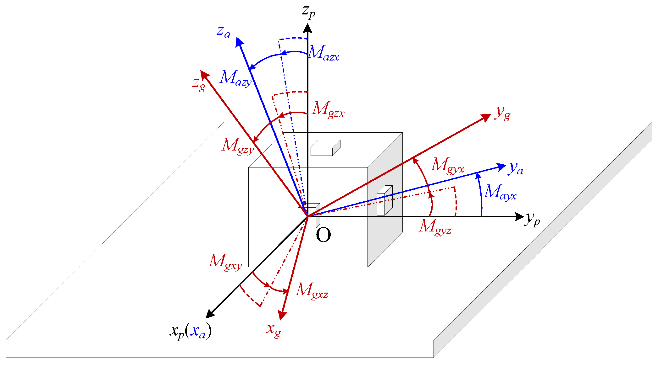
Figure 1. The coordinate systems for a-frame, g-frame, and p-frame.
Electronics 14 04277 g001
Figure 2. Self-contained calibration for parameters in the MIMU output model based on residual velocity measurement.
Electronics 14 04277 g002
Figure 3. Spherical rotating platform: (a) scheme of designed MIMU; (b) spherical platform; (c) installation of spherical platform.
Electronics 14 04277 g003
Figure 4. Scheme of the oriented rotation.
Electronics 14 04277 g004
Figure 5. Observability curves for the parameters in the MIMU output model: (a) observability curve for zero bias of gyroscope; (b) observability curve for zero bias of accelerometer; (c) observability curve for scale factor error of gyroscope; (d) observability curve for scale factor error of accelerometer; (e) observability curve for non-orthogonality error of gyroscope; (f) observability curve for non-orthogonality error of accelerometer.
Electronics 14 04277 g005
Figure 6. Estimation result of parameters in the MIMU output model for numerical simulation: (a) estimation curve for zero bias of gyroscope; (b) estimation curve for zero bias of accelerometer; (c) estimation curve for scale factor error of gyroscope; (d) estimation curve for scale factor error of accelerometer; (e) estimation curve for non-orthogonality error of gyroscope; (f) estimation curve for non-orthogonality error of accelerometer.
Electronics 14 04277 g006
Figure 7. Self-made MIMU.
Electronics 14 04277 g007
Figure 8. Self-made spherical platform and bracket.
Electronics 14 04277 g008
Figure 9. Estimation result of parameters in the MIMU output model for one group experiment: (a) estimation curve for zero bias of gyroscope; (b) estimation curve for zero bias of accelerometer; (c) estimation curve for scale factor error of gyroscope; (d) estimation curve for scale factor error of accelerometer; (e) estimation curve for non-orthogonality error of gyroscope; (f) estimation curve for non-orthogonality error of accelerometer.
Electronics 14 04277 g009
Figure 10. Comparison of the static navigation results before and after decoupling: (a) attitude error for static navigation calculation; (b) velocity error for static navigation calculation; (c) position error in static navigation calculation before decoupling; (d) position error in static navigation calculation after decoupling.
Electronics 14 04277 g010aElectronics 14 04277 g010b
Figure 11. Installation of MIMU.
Electronics 14 04277 g011
Figure 12. Dynamic scenarios experiment.
Electronics 14 04277 g012
Figure 13. Position error for dynamic scenarios before and after decoupling: (a) position error in dynamic scenarios before decoupling; (b) position error in dynamic scenarios after decoupling.
Electronics 14 04277 g013
Table 1. Parameter setting for the simulation of the Kalman filter.
ParametersValues
Initial velocities(0 m/s, 0 m/s, 0 m/s)
Initial positions(120.350440°, 30.314850°, 0 m)
Initial misalignment angles(0°, 0°, 0°)
Initial matrix of PP0(1, 1), P0(2, 2), P0(3, 3)(0.1°)2
P0(4, 4), P0(5, 5), P0(6, 6)(0.01 m/s)2
P0(7, 7), P0(8, 8), P0(9, 9)(0.1 m)2
P0(10, 10), P0(11, 11), P0(12, 12)(100°/h)2
P0(13, 13), P0(14, 14), P0(15, 15)(5 mg)2
P0(16, 16), P0(17, 17), P0(18, 18),
P0(19, 19), P0(20, 20), P0(21, 21)
(6000 ppm)2
P0(22, 22), P0(23, 23), P0(24, 24),
P0(25, 25), P0(26, 26), P0(27, 27),
P0(28, 28), P0(29, 29), P0(30, 30)
(3000″)2
else0
Matrix of QQ(1, 1), Q(2, 2), Q(3, 3)(0.36°/√h)2
Q(4, 4), Q(5, 5), Q(6, 6)(100 μg/√Hz)2
else0
Matrix of RR(1, 1), R(2, 2), R(3, 3)(0.01 m/s)2
else0
Table 2. Parameter setting for the simulation of MIMU.
Error Parameters of Each Sensor in MIMUParameter Value Settings
Three-axis gyroscope
parameters
Zero bias (°/h)20
Scale factor error (ppm)2000
Non-orthogonal error (″)500
Angle random walk (°/√h)0.78
Three-axis accelerometer
parameters
Zero bias (mg)2
Scale factor error (ppm)2000
Non-orthogonal error (″)500
Velocity random walk (μg/√Hz)816
Table 3. Statistical results for parameters’ estimation of the self-contained calibration.
Gyroscope
Parameters
Set
Value
Estimated ValueRelative
Error
Accelerometer
Parameters
Set
Value
Estimated ValueRelative
Error
bgx (°/h)2018.98−5.10%bax (mg)21.99−0.50%
bgy (°/h)2020.190.95%bay (mg)21.99−0.50%
bgz (°/h)2019.52−2.40%baz (mg)21.99−0.50%
δkgx (ppm)20001996.30−0.19%δkax (ppm)20002005.040.25%
δkgy (ppm)20001921.70−3.92%δkay (ppm)20002009.390.47%
δkgz (ppm)20001860.76−6.96%δkaz (ppm)20002002.820.14%
Mgxy (″)500574.4214.88%Mayx (″)500501.890.38%
Mgxz (″)500435.78−12.84%Mazx (″)500497.35−0.53%
Mgyx (″)500451.94−9.61%Mazy (″)500500.090.02%
Mgyz (″)500467.42−6.52%
Mgzx (″)500526.775.35%
Mgzy (″)500541.158.23%
Table 4. The performance specifications of the used ADXRS453 and ADXL343 in our design.
Performance SpecificationsValues for Each Axis (x, y, z)
ADXRS453Full scale (°/sec)±300
Bias instability (°/h)14.84/4.56/15.15
Angle random walk (°/√h)0.85/0.86/0.91
ADXL343Full scale (g)±16
Bias instability (μg)101/57/46
Velocity random walk (μg/√Hz)561/459/425
Table 5. Statistical results for parameters’ estimation of three groups of experiments.
Parameters in MIMU
Output Model
Calibration GroupsMean Value for
Calibration
Standard
Deviation
Groups 1Groups 2Groups 3
bgx (°/h)−2456.51−2440.17−2444.80−2447.166.88
bgy (°/h)−335.21−310.00−290.45−311.8918.32
bgz (°/h)2588.042593.462602.902594.806.14
δkgx (ppm)−13,341.89−14,394.83−12,081.95−13,272.89945.49
δkgy (ppm)−18,418.66−17,755.49−17,170.98−17,781.71509.70
δkgz (ppm)−18,710.92−16,919.01−18,019.40−17,883.11737.86
Mgxy (′′)−1979.05−2712.62−2559.65−2417.11315.99
Mgxz (′′)3530.532769.773644.303314.87388.23
Mgyx (′′)2965.193183.872635.602928.22225.35
Mgyz (′′)−760.60−1603.20−763.82−1042.54396.45
Mgzx (′′)−3438.19−2913.46−3243.23−3198.29216.56
Mgzy (′′)3802.913846.203602.603750.57106.11
bax (mg)45.3345.4443.7944.850.75
bay (mg)12.5012.6911.7512.310.41
baz (mg)−2.14−2.22−1.95−2.100.11
δkax (ppm)−26,169.22−28,250.45−25,836.42−26752.031068.22
δkay (ppm)−11,391.84−13,111.82−10,844.88−11,782.85965.89
δkaz (ppm)8577.218272.678538.018462.63135.27
Mayx (′′)−27.32238.96−55.2652.13132.60
Mazx (′′)−1704.82−635.94−1867.02−1402.59546.14
Mazy (′′)350.77575.16430.40452.1192.88
Disclaimer/Publisher’s Note: The statements, opinions and data contained in all publications are solely those of the individual author(s) and contributor(s) and not of MDPI and/or the editor(s). MDPI and/or the editor(s) disclaim responsibility for any injury to people or property resulting from any ideas, methods, instructions or products referred to in the content.