Abstract
The effective management of energy interactions in multi-island microgrid systems presents a significant challenge due to the geographical dispersion of islands. To address this, this paper proposes a hierarchical distributed optimization strategy based on the alternating direction method of multipliers (ADMM). The strategy features a two-layer architecture: the upper layer employs the ADMM to solve the system-level optimal power flow problem and generates distributed node marginal electricity prices (DLMPs) as clear economic coordination signals. The lower layer consists of individual island microgrids, which independently and in parallel solve their internal security-constrained economic dispatch (SCED) problems upon receiving the converged DLMP signals. This layered decoupling design functionally separates system-level coordination from microgrid-level optimization and enhances privacy protection by preventing the exposure of internal cost functions and operational constraints during upper-layer iterations. Case studies demonstrate that the proposed strategy reduces total operating costs by 10.3% compared to a centralized approach, while also significantly decreasing communication data volume by 83% and ensuring robust privacy protection. The algorithm exhibits good scalability with sublinear growth in iteration counts as the system scales, validating its effectiveness and practical potential for enhancing energy management in multi-island microgrid systems.
1. Introduction
In recent years, the relentless growth in global energy demand coupled with escalating environmental challenges has underscored the critical importance of Distributed Energy Systems (DES) in energy management. Microgrids, as a technology adept at the flexible integration of distributed energy resources, have garnered significant attention for their ability to enhance energy utilization efficiency, bolster system reliability, and mitigate environmental pollution [1,2]. This is particularly pertinent in isolated regions such as islands; they can be connected to the public power grid under normal circumstances and can operate independently in the event of a disconnection from the public power grid. Multiple island microgrids can also be connected to each other to achieve complementary energy resources.
However, as the proliferation and scale of microgrids escalate, the imperative to effectively manage and optimize these distributed energy systems has risen to a pressing challenge [3]. Traditional centralized energy management methodologies, cumbersome with their prerequisite for substantial communication and computational resources, struggle to meet the demands of large-scale distributed systems. Consequently, distributed energy management strategies have emerged as a burgeoning focal point within the research community. Among these, the alternating direction method of multipliers (ADMM) stands out as an effective distributed optimization algorithm, widely employed for its remarkable efficiency and convergence properties in addressing large-scale optimization issues. The ADMM’s approach involves the decomposition of the overarching problem into multiple sub-problems, addressed in parallel, with iterative global variable updates to converge upon the global optimum solution. This method is particularly adept at handling distributed energy management challenges, as it facilitates optimal system scheduling while safeguarding the privacy of each microgrid [4,5].
Building upon these advancements, Reference [6] introduces a multi-energy management method for interconnected multi-microgrid systems, employing multi-agent deep reinforcement learning. This approach is capable of optimizing energy allocation, thereby enhancing the operational efficiency and reliability of the system. Reference [7] delves into the elastic control challenge of photovoltaic modules within smart microgrids, addressing the stability concerns under extreme weather conditions and grid vulnerabilities. Expanding on the work presented in Reference [7], Reference [8] further investigates the power flow calculation challenges under the new power system’s carbon peak and carbon neutrality objectives, offering a novel computational framework for energy optimization. Reference [9] establishes a low-carbon economic operation model for multi-microgrid peer-to-peer (P2P) networks, using the convergent and privacy-friendly alternating direction method of multipliers (ADMM) to decompose the original problem into two sub-problems for solution. References [10,11] proposed a fully decentralized, adjustable, and robust operation framework for achieving the coordinated operation of ADNs and MMGs in order to reduce the solution conservatism in dealing with renewable energy uncertainty. Reference [12] proposes a distributed optimization-based elastic microgrid energy management algorithm, presenting a fresh solution for energy management in distributed multi-microgrids. Subsequently, Reference [13], expanding on the foundation laid by Reference [12], introduces a distributed algorithm based on the ADMM for managing multiple microgrids, enhancing the algorithm’s efficiency and scalability. Reference [14] derived a distributed iterative algorithm for solving optimization problems established by static and dynamic constraints by combining the ADMM and the distributed resource allocation (DRA) algorithm. References [15,16,17,18] delve into the optimal energy management of multiple microgrids under a distributed robust optimization framework, tackling the uncertainty inherent in energy trading. References [19,20] further explore multi-objective energy management in renewable energy and electric vehicle contexts, contributing innovative ideas for the sustainable progression of distributed multi-microgrids. Although the above research confirms the effectiveness of the ADMM in multi-microgrid management, its mainstream paradigm typically embeds the complete internal optimization model of each microgrid (a complex mixed integer nonlinear programming problem) directly into the iterative loop of the ADMM. This ‘fully embedded’ paradigm has two inherent limitations: firstly, in each iteration, the microgrid needs to expose its internal cost function and sensitive operational constraints to the coordinator or adjacent microgrids, which poses a risk of privacy leakage; secondly, coordination signals are often abstract Lagrange multipliers with unclear economic meanings, making it difficult to directly guide efficient market-oriented transactions. To address the above issues, this article proposes a ‘layered decoupling’ architecture, whose core innovation and differences lie in the following:
- 1.
- Functional decoupling: The upper-level ADMM is only responsible for solving the system-level optimal power flow problem based on physical power flow, and its output is the distributed node marginal electricity price with clear economic signals rather than the specific scheduling instructions of the lower level.
- 2.
- Privacy enhancement: After receiving the converged final electricity price signal, the lower-level microgrids independently and in parallel solve their internal optimization problems. The private costs and operational constraints within the microgrid do not need to be exposed in the upper ADMM iterations, achieving stronger privacy protection.
2. Multi-Island Microgrid Energy Management Architecture
The energy management architecture of the multi-island microgrid system is shown in Figure 1, where each island microgrid consists of conventional distributed power sources, renewable energy, battery energy storage systems, and flexible loads, and is connected to the local power grid. In the distribution system, each island microgrid is considered a user who can sell or purchase electricity from other island microgrids. In Figure 1, the dashed line represents a bidirectional communication network that can be constructed through wireless sensors or other wired infrastructure, while the solid line represents the power network. In order to promote the on-site consumption of renewable energy within microgrid clusters and simplify initial analysis, this article sets the electricity trading price between microgrids to be lower than their purchase price from the main grid. This mechanism is designed to provide economic incentives for energy exchange between islands. We recognize that in the actual electricity market, electricity prices are dynamically changing. However, the method framework proposed in this article is universal, and DLMP signals can dynamically reflect network congestion and losses, which can seamlessly integrate into more complex real-time electricity pricing mechanisms in the future and each island microgrid is equipped with an island energy controller and an ADMM agent. The island energy controller is responsible for controlling the controllable devices under its control and uploading local information to the ADMM agent; ADMM agent is responsible for power exchange and information exchange between multiple island microgrids.
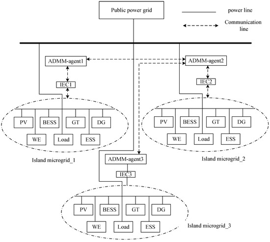
Figure 1.
Energy management architecture of multi-island microgrid system.
3. Energy Interaction Management Strategy for Multi-Island Microgrids Based on the ADMM
3.1. Optimal Power Flow for Multi-Island Microgrids
A system of interconnected autonomous microgrids, referred to as a multi-island microgrid, comprises a collection of individual microgrids. Each microgrid is delineated by a set of nodes, denoted as Nnode = {0, …, N}, and a corresponding set of electrical lines, denoted as Nline. The nodes that interface with the transmission network are designated as node 0, while the remaining N nodes correspond to the points of common coupling (PCC) between the island microgrid and the distribution network. For each node i∈Nnode∖{0}, there is a distinct parent node, denoted by Ai, and a set of child nodes, denoted by Ci. The electrical line interconnecting node Ai with node i is identified as line i, with its resistance and reactance characterized by ri and xi respectively. The primary goal of the optimization objective function is to reduce the operational costs of the system over time, subject to the constraints of power flow as detailed in Equations (2)–(5).
where represents the power at time t node i.
Constraints:
(1) Node voltage
where is the voltage at time point i at time t. is the active power flowing through line i at time t. is the reactive power flowing through line i at time t. is the square of the current flowing through line i at time t. is the reactance of line i. is the resistance of line i.
(2) Power balance
where represents the active power at time t at point j. is the active power at time t and time point i. represents the active power demand or generation at time t and time point.
(3) Reactive power balance
where represents the reactive power consumption or generation at time t at point i. is the reactive power demand or supply at time t and time point i.
(4) Line constraints
where is the voltage at time point i at time t. is the active power flowing through line i at time t. is the reactive power flowing through line i at time t. is the square of the current flowing through line i at time t.
3.2. Optimal Power Flow Solution Strategy Based on the ADMM
The ADMM algorithm is used to solve optimal power flow problems mainly because it supports distributed computing, which enables parallel processing of large-scale power system problems on multiple computing units, thereby improving efficiency. In addition, the ADMM algorithm can protect privacy as it allows for coordinated control among island microgrids without sharing all internal information. This is particularly important for distribution networks that include multiple island microgrids, as each island microgrid may wish to preserve the privacy of its operations.
The interconnection of power flow equations across adjacent entities complicates the decomposition of the optimal power flow problem, preventing its distributed processing by alternating direction method of multipliers (ADMM) agents. Each ADMM agent is tasked with solving subproblems that encompass both the local variables x of the primary agent and the global variables z associated with the neighboring coupled subproblems. Consequently, the outcomes of these subproblems are contingent upon the alignment of global variable measurements to establish consensus. The optimization process, facilitated by the augmented Lagrangian method for the ADMM, is bifurcated into two sequential phases: the update of local variables and the update of global variables, both of which are addressed collaboratively by each ADMM agent. In executing the ADMM algorithm, each agent takes into account the local variables xi,t of the node, the sub-local variables xj,i, the voltages vA,t of the connected nodes, and the global variables zi,t.
where pi,t signifies the active power input at node i within the electrical grid, λi,t denotes the Lagrange multiplier associated with node i at time t, T encompasses the operational timeframe, Ci delineates the subset of child nodes connected to node i in the distribution network, ρ is a predefined constant, vi,t is the voltage magnitude squared at node i, ri represents the resistance of the line segment at node i, Pi,t is the active power flow through line segment i in the power grid, Pj,i is the active power flow at sub-node j connected to node i, xi is the reactance of the line segment at node i, Qi,t is the reactive power flow along line segment i in the power grid, Qj,i is the reactive power flow at sub-node j connected to node i, li,t is the current magnitude squared at line segment i, lj,i is the current magnitude squared at sub-node j connected to node i, Nline is the collection of all line segments within the distribution network, and qi,t is the reactive power input at node i. Nnode represents the total set of nodes within the distribution network. The objective function (6) is formulated to minimize the overall power supply expenditure while bridging the disparity between local and global variables to establish a consensus. Within the proposed approach, the transmission system’s power supply cost, denoted by fi,t(x) as per Equation (10), serves as the target value for the ADMM algorithm’s optimization.
where LMPt is the marginal price of the node. The island energy controller considers the costs associated with island microgrid resources (i.e., traditional distributed energy, battery storage systems, and flexible loads) in the scheduling process of island microgrids.
The formula for updating the global variable (z) is as follows:
The objective function (11) is crafted to optimize the global variables by incorporating the latest revisions of the local variables while respecting the network’s constraints. The ADMM algorithm is decomposed into several standalone cyclical sub-problems, which can be processed concurrently, leading to a reduction in overall computational duration.
3.3. Calculation Method for Distributed Energy Interaction Price
When optimizing resource scheduling for each MGCU, the electricity trading price between the main grid and the MGCU will be considered. Each ADMM agent requires a method to estimate the electricity trading price between the island microgrid and the main grid, which requires a signal influenced by energy exchange prices. Therefore, the concept of distributed node marginal electricity prices is utilized to generate energy exchange price control signals. Considering the node marginal electricity price received from the power grid as a substation node, the distributed node marginal electricity price DLMPAi of its main node can be used to calculate the distributed node marginal electricity price DLMPi of each sub node, which can be expressed by the following equation:
The ratio ΔLossi/ΔPi represents the quotient of the additional ΔLossi at node i and the marginal power difference ΔPi. The losses generated due to power flow in each line i can be calculated using the following formula:
In this regard, an increase in Pi may increase Lossi, which can be expressed by the following equation:
Therefore, ADMM agents are capable of autonomously determining energy exchange price signals through the exchange of information with adjacent agents during the ADMM computation phase. In essence, the proposed approach empowers ADMM agents to independently compute their energy exchange price signals in a decentralized fashion at each time interval of the day-ahead operational management for multi-island microgrid systems. As a result, the proposed method obviates the need for a centralized operator within the system, fostering a fully distributed control framework for multi-island microgrid distribution networks. Ultimately, the formulated energy exchange price signals can be transmitted directly from the island energy controller to the local control unit, thereby mitigating operational risks.
4. Energy Optimization Models for Island Microgrids
Drawing from the operational outputs and energy consumption patterns of micro gas turbines, diesel generators, and energy storage systems, as well as the stochastic generation traits of photovoltaic and wave energy within island microgrids, a Security Constrained Economic Dispatch (SCED) framework is formulated. The SCED’s objective function is designed to reduce the operational expenditures of the island microgrid system. This encompasses the fuel expenses detailed in the initial phase, the amortized electricity costs associated with the generation/charging and discharging of equipment, and the financial implications of electricity transmission transactions between the island microgrid and the distribution network. The mathematical representation of this objective is articulated in the subsequent equation:
(1) Micro gas turbine model:
The mathematical model of the cost generated by the consumption of natural gas fuel during the power generation process of a micro gas turbine can be expressed as follows:
where represents the price per unit of natural gas fuel, represents the low heating value of natural gas combustion (usually 9.7 kWh/m3), represents the scheduled power generation of the micro gas turbine, and represents the power generation efficiency of the micro gas turbine, which varies with the size of .
(2) Diesel generator model:
Similar to micro gas turbines, the mathematical model of the cost generated by diesel fuel consumption during the power generation process of a diesel generator, denoted as , can be expressed as:
where represents the price per unit of diesel fuel, represents the combustion heat value of diesel (usually 46,050 kJ/kg), represents the scheduled power generation of the diesel generator, and represents the power generation efficiency of the diesel generator, which varies with the size of ;
(3) Photovoltaic system model:
The economic expenditure incurred in the electricity generation cycle of photovoltaic (PV) systems is commonly quantified using the Levelized Cost of Energy (LCOE) metric. This metric represents the mean per-unit cost of electricity produced by the PV project, factoring in the costs and energy output over its entire lifecycle, discounted at a specific rate. In essence, it equates to the present value of cumulative costs over the project’s lifespan, divided by the present value of the total electricity generated. This figure is often juxtaposed with market electricity rates and holds significant value for decision-making purposes. The formula for calculating the LCOE of a photovoltaic power generation system is presented below:
where represents the construction cost of the photovoltaic system, represents the asset depreciation and taxes during the lifecycle of the photovoltaic system, represents the operation and maintenance cost, represents the present value of the residual value of fixed assets, and represents the power generation of the photovoltaic system. According to the Renewable Energy Generation Cost Report released by IRENA in 2020, the levelized cost of electricity for photovoltaic power generation is approximately USD 0.044 per kWh. According to this conclusion, the cost model of photovoltaic systems can be represented by the following equation:
where is the generation cost of the photovoltaic system based on the levelized cost of electricity, is the annual attenuation coefficient (taken as 0.005), is the number of years the photovoltaic system has been in operation, is the real-time power generation of the photovoltaic system, and is the real-time maximum power generation of the photovoltaic system, which is related to the parameters of the photovoltaic panel equipment and the lighting conditions. Taking hourly scheduling as an example, X is the typical daily hourly light intensity, S is the area of the photovoltaic array, and η is the photovoltaic efficiency.
(4) Distributed energy storage system model:
Similar to the cost of photovoltaic power generation, the charging and discharging cost of distributed energy storage systems is also measured by the levelized cost of electricity (LCOE). The cost model of the energy storage system in the charging and discharging state is as follows:
where represents the charging and discharging cost of the distributed energy storage system, and represent the levelized electricity cost of the charging and discharging states, respectively. β is the cost penalty coefficient (taken as 0.1 in the example), and SoC is the state of charge for the current period. is the charging/discharging power. When , it means working in the charging state and absorbing electricity from the island microgrid side. Conversely, when , it means in the discharging state and providing electricity to the island microgrid;
(5) Energy storage vessel model:
The cost model for charging and discharging energy storage ships is similar to that of distributed energy storage systems, but the difference is that energy storage ships may include other forms of energy storage systems besides battery storage, such as hydrogen storage and gas storage equipment. The charging and discharging cost models for the two other forms of energy storage systems mentioned above can be represented by the following equation:
where and respectively represent the cost functions of energy storage charging and discharging carried by hydrogen and gas storage equipment, and respectively represent the corresponding levelized electricity costs, and and respectively represent the efficiency of the conversion of electrical energy with hydrogen and natural gas during the charging and discharging process.
(6) Wave energy generation system model:
Wave energy refers to the total kinetic and potential energy of ocean surface waves within a wavelength range. Wave energy has a large reserve and low energy density, and also has strong seasonal characteristics. The power density model for wave energy generation is:
where is the power density per unit wavefront width, h is the height of the wave, and Tw is the wave period. Waves are greatly affected by sea surface wind speed, and wave energy data can be indirectly obtained through wind measurement.
(7) Electricity transaction costs between island microgrids and distribution networks
The variable Cex(t) denotes the economic cost associated with the electricity transactions between the island microgrid and the distribution network. A positive value of Cex(t) signifies that the island microgrid is procuring electricity from the distribution network, whereas a negative value suggests that the island microgrid is supplying electricity to the distribution network. The magnitude of Cex(t) is contingent upon the prevailing price of electricity and can be formulated by the ensuing equation:
where and respectively represent the prices at which the island microgrid purchases and sells units of electricity from and to the distribution network at time t. represents the direction of electricity power flow, with a value greater than zero indicating that the island microgrid purchases electricity and a value less than zero indicating that it sells electricity.
The constraints of the SCED problem include power balance constraints for island microgrids, upper and lower limits for equipment rated power generation, upper and lower limits for equipment rated capacity, and ramp up power constraints. The power balance constraint for the operation of the island microgrid is an equality constraint, which requires the balance of energy supply and demand in the island microgrid at any given moment, which can be expressed by the following equation:
The power generation scheduling plan of micro gas turbine and diesel generator equipment is limited by the rated power generation and ramp up power of the equipment itself, and its inequality constraints can be expressed by the following equation:
The power generation of photovoltaic systems and wave energy is not only limited by equipment factors such as the installation area of photovoltaic panels and wave panels, but also by environmental factors such as lighting, temperature, obstruction, and wave conditions. The inequality constraints can be expressed by the following equation:
The power dynamics of both distributed energy storage systems and energy storage vessels are governed not solely by the maximum and minimum thresholds of their rated charging and discharging capabilities but also by the capacity limits of the energy storage units to prevent overcharging or overdischarging scenarios. These constraints are articulated through the following inequality constraints:
Rewrite the SCED problem based on the augmented Lagrangian multiplier method that considers constraint conditions, where the constraint conditions only consider the equality constraint of power supply and demand balance in island microgrids. The general mathematical model of the augmented Lagrangian multiplier method under equality constraints is represented by the following equation:
The core significance of using iterative optimization method to solve the augmented Lagrangian function is that in each iteration step, based on the given penalty factor and Lagrangian multiplier , the minimum value point of the augmented Lagrangian function satisfies the following condition:
Therefore, the iterative solution algorithm steps for the augmented Lagrangian function can be represented by the following pseudocode:
| Augmented Lagrangian Function—Iterative Solution Algorithm | ||
| Select the initial point , Lagrange multiplier , penalty factor update constant , constraint violation constant , accuracy requirement , and initialization cycle number ; | ||
| When the convergence condition is not met, loop: | ||
| Using as the initial point, solve for to obtain the solution that satisfies the accuracy condition ; | ||
| if , execute: | ||
| Return approximate solution , , terminate iteration; | ||
| Otherwise, execute: | ||
| Update Lagrange multipliers: ; | ||
| Update penalty factor: | ||
| End | ||
| End cycle | ||
The optimal economic dispatch strategy obtained by the iterative optimization method mentioned above only considers the equality constraints of power balance in island microgrids, without taking into account constraints such as equipment rated power and capacity. Therefore, to check the satisfaction of the above optimal solution under inequality constraints, if there is an operation plan that exceeds the upper/lower limits, fix the equipment operation plan at the corresponding upper/lower limit power generation or charging/discharging power, which can be expressed by the following equation:
After fixing the operating power of the adjustable resource devices mentioned above, execute step three again to optimize the safety constraints and economic scheduling of the remaining devices. The new SCED problem can be expressed as follows:
where represents a set of devices with fixed operating power, and is their fixed upper and lower limit operating power. Repeat this step until the optimal solution of the augmented Lagrangian function satisfies all inequality constraints on device power and capacity, proving that the optimal solution for the decentralized collaborative scheduling model of the lower-level island microgrid has been found.
As shown in the overview, the algorithm flow is shown in Figure 2, which is divided into two parts: upper-level ADMM optimal power flow and lower-level SCDE optimization. The specific steps are as follows:
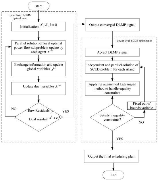
Figure 2.
Flow Chart of Hierarchical Distributed Energy Interaction Management Strategy Based on the ADMM.
Upper layer: ADMM optimal trend (optimal trend solving)
- (1)
- Initialization operation: Set the initial global variable , dual variable , and iteration count
- (2)
- Each agent solves the local optimal power flow subproblem in parallel and updates the local variables
- (3)
- Each agent exchanges information and updates the global variable
- (4)
- Update the dual variable
- (5)
- Determine whether the original residual and the dual residual are less than the preset threshold : If not, return to step 2 to continue iteration; if it meets the requirements, output the converged DLMP (distributed local marginal price) signal and enter the lower-level process.
Lower level: SCDE optimization (scheduling plan solving)
- (1)
- Receive the DLMP signal output from the upper layer.
- (2)
- Each island independently and parallelly solves the SCED (Safety Constrained Economic Dispatch) problem.
- (3)
- Apply augmented Lagrangian method to handle equality constraints.
- (4)
- Determine whether the inequality constraint is satisfied: If it is satisfied, continue the process; if not, fix the out of bounds variable and return to step 2 to solve the SCED problem again.
- (5)
- Output the final scheduling plan.
5. Example Analysis
In order to verify the effectiveness of the designed algorithm, this paper assumes 1 h as a time period and optimizes scheduling within one day (00:00–24:00). A multi-island microgrid system composed of three interconnected island microgrids is taken as an example for numerical analysis. As shown in Figure 3, the system is directly connected to the power grid, and the island microgrid 1 in the system contains PV, BESS, Load, GT, and DG; island microgrid 2 contains PV, BESS, Load, GT, DG, WE, and ESS; island microgrid 3 contains PV, BESS, Load, and DT. The equipment parameters within the island microgrid are shown in Table 1. The daily load and new energy output of each island are shown in Figure 4. It can be seen from the figure that the photovoltaic power generation of the three islands follows a normal distribution, reaching the maximum power generation around 13:00; the load of Island 1 shows a clear bimodal characteristic; the load of Island 2 is a unimodal load, with maximum electricity consumption at night. Island 3 has a relatively stable load and a relatively small size. Table 2 shows the operating costs of various devices in the island microgrid. Using the Windows 10 operating system and Python 3.8 environment, the solver implements the ADMM algorithm and combines it with the SciPy optimization library to handle nonlinear constraints. The key parameter settings are as follows: penalty factor ρ: After parameter sensitivity testing, select the optimal value of 1.0 (test range: 0.1–10.0), stop threshold: original residual and dual variable residual are both set to 0.001, maximum iteration times: 500 (all test scenarios converge within this range).
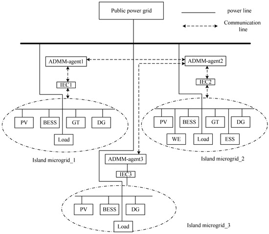
Figure 3.
Multi-island microgrid architecture diagram.

Table 1.
Equipment parameters of the island microgrid.
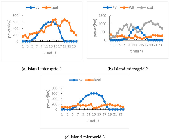
Figure 4.
Load and new energy output curves of microgrids on various islands.

Table 2.
Operating Costs of Island Microgrid Equipment.
5.1. Scheduling Results
5.1.1. Internal Energy Optimization Results of Island Microgrids
From Figure 5, it can be seen that photovoltaic power generation reaches its peak during the daytime period (approximately from 12:00 to 13:00), while load demand is higher during the noon and evening periods. The battery energy storage system charges during excess photovoltaic power generation and discharges during peak load demand. Purchase electricity from Island 2 and 3 microgrids from 7:00 a.m. to 9:00 a.m. and from 2:00 p.m., 3:00 p.m., and 5:00 p.m. in the afternoon to meet your own energy needs. Due to the fact that each island microgrid first achieves internal self-balancing and decides whether to sell or buy electricity based on its own power, as shown in Figure 5b, it can be seen that after self-balancing, only a small amount of electricity is sold to the island microgrid group. Due to the depletion of energy storage on the island during the evening (approximately from 19:00 to 21:00) and the lack of power supply on other islands, micro gas turbines and diesel generators are being started to supplement the power gap.
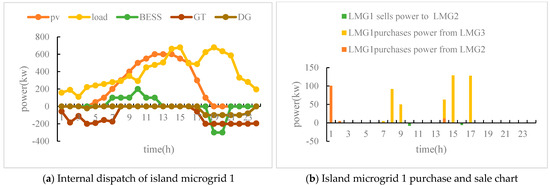
Figure 5.
Energy Optimization Results of Island Microgrid 1.
From Figure 6, it can be seen that there are many distributed power generation devices in island microgrid 2, but the load of island microgrid 2 is relatively high. Before 9–16 o’clock, a large amount of electricity is purchased from island microgrid 3 to make up for the load gap. Similar to Island microgrid 1, all energy supply equipment operates from 19:00 to 20:00 in the evening, and the load gap is still large, so electricity can only be purchased from the higher-level power grid; at 1 o’clock, wave energy generated more electricity than the load, and the excess electricity was sold to island microgrid 1.

Figure 6.
Energy Optimization Results of Island Microgrid 2.
From Figure 7, it can be seen that the load of island microgrid 3 is very small, and the electricity generated by new energy can basically meet the load. The remaining electricity is mainly used to support island microgrid 1 and 2. Between approximately 10 and 15 o’clock, island microgrid 3 can meet the energy consumption of 1 and 2, and the remaining electricity is sold to the higher-level power grid.

Figure 7.
Energy Optimization Results of Island Microgrid 3.
5.1.2. Power Exchange Results Between Islands and Main Networks
From Figure 8, we can see that the load of island microgrid 1 and 2 is relatively high, and the main power generation equipment supplies energy to the load. Moreover, there will be a significant load gap in the evening (approximately from 17:00 to 22:00), and power can only be purchased from the higher-level grid. Island microgrid 3 can be used as a power supply microgrid. Between 13:00 and 14:00, the maximum photovoltaic power generation occurs. When sold to other island microgrids, the remaining electricity is sold to the higher-level grid for profit.
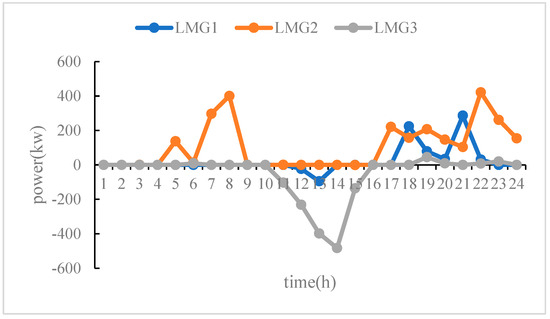
Figure 8.
Power Exchange between Islands and the Main Network.
From Table 3, it can be seen that the total cost of the layered distributed energy interaction management strategy based on ADMM is lower than that of centralized and multi-agent strategies, reducing by 11.5% and 2.22%, respectively, and lowering operating costs. The method proposed in this article has good economic benefits.

Table 3.
Operating Costs of Island Microgrids under Different Strategies.
A comparison was made between the privacy protection performance of centralized, multi-agent strategies, and the strategy proposed in this paper in terms of cost function parameter protection, implementation status protection, and device constraint condition protection, as shown in Table 4:

Table 4.
The privacy protection performance of different strategies was compared.
While achieving lower operating costs, the hierarchical distributed method proposed in this paper performs outstandingly in key privacy indicators: the cost function and device constraints are fully protected, the operating status only exposes necessary boundary information, and the communication data volume is reduced by 83%.
5.1.3. Sensitivity Analysis
To further verify the reliability of cost differences between different strategies, we conducted statistical significance tests. By changing the island load curve and the fluctuation range of renewable energy output (±10%), four different daily operating scenarios were generated, and four independent daily operating cost samples of three strategies were obtained, as shown in Table 5. We use a paired sample t-test to evaluate whether the cost difference between the ADMM strategy and the other two strategies is statistically significant (significance level α is set to 0.05), as shown in Table 6.

Table 5.
The total operating costs of the three strategies under different scenarios.

Table 6.
Results of the statistical significance test.
The operating costs and inspection results under different scenarios are shown in the following table:
Although the number of test scenarios has decreased, the above table shows that the p-values (0.0021 and 0.0153) of the two comparisons are still below the significance level of 0.05. This indicates that even under limited scenario changes, the cost difference between the ADMM strategy proposed in this paper and the comparative strategy still has statistical significance.
The absolute values of the t-statistic are all much greater than the critical value, indicating that the observed cost reduction effect is systematic and consistent, rather than an accidental result of individual scenarios. Based on the sensitivity analysis, we can draw a more universal conclusion: compared to the comparative strategy, the economic advantage of the strategy proposed in this article is stable, robust, and statistically significant.
5.2. Convergence Analysis of the ADMM Algorithm
Due to the randomness of the load demand of the microgrid and renewable energy generation, it will affect the solution of the optimal scheduling plan to a certain extent, and also affect the convergence of the algorithm in this paper. In order to analyze the convergence of the proposed algorithm, the raw residuals and dual residuals of each period are recorded, and the range of the raw residuals and dual residuals is set to 0.001. In Figure 9 and Figure 10, each line represents a period of time with an interval of 3 h. After about 150–200 iterations, the above two residuals converge to the expected value, indicating that the proposed algorithm has good convergence.
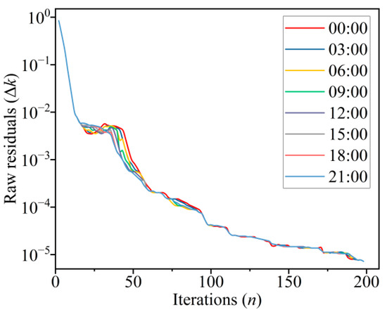
Figure 9.
Raw residuals curve.
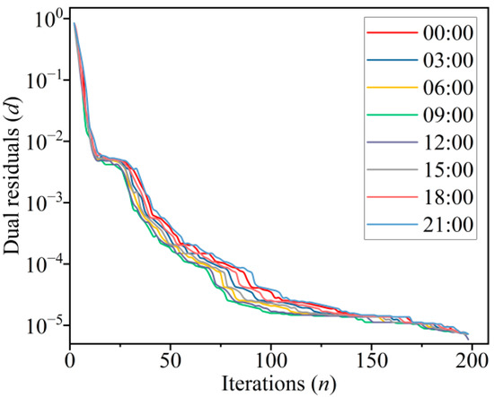
Figure 10.
Dual residuals curve.
5.3. Scalability Analysis
To verify the applicability of the proposed algorithm in large-scale systems, this section tested its scalability. On the basis of the original three-island microgrid system, a testing system consisting of 5, 10, and 20 island microgrids was constructed by copying and fine-tuning parameters. The algorithm performance is shown in Figure 11 and Table 7.
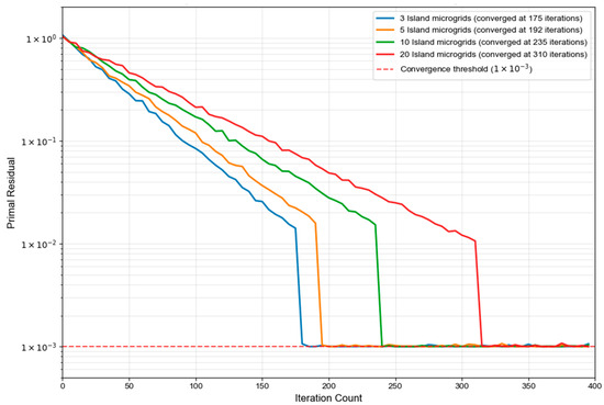
Figure 11.
Convergence characteristics under different microgrid scales.

Table 7.
Algorithm Performance under Different Scale Systems.
From Figure 11, it can be seen that all curves can reliably converge to the preset threshold of 0.001, verifying the convergence reliability of the algorithm at various scales. As the system size increases from 3 microgrids to 20, the number of iterations required for convergence increases from 175 to 310, with a growth rate of sublinear, proving that the algorithm has good scalability. From Table 7, it can be seen that as the system size expands, the number of iterations and computation time of the algorithm increase sublinear. This indicates that the hierarchical distributed strategy proposed in this article has good scalability and can effectively address the challenges brought by the expansion of multi-island microgrid systems. The increase in computation time is mainly due to the increase in the number of sub-problems in parallel computing and the slight increase in the number of iterations required to reach consensus, but there is no problem of computational explosion, which proves the practical potential of this strategy in large-scale systems.
Figure 12 analyzes the impact of penalty parameter ρ on the convergence speed of the ADMM algorithm using this bar chart. The convergence performance of ρ was tested within the range of 0.1 to 10.0, and the results showed that when ρ = 1.0, the convergence speed was the fastest, requiring only 175 iterations. When ρ deviates from the optimal value, the convergence performance significantly decreases. When ρ = 0.1, 285 iterations are required, and when ρ = 10.0, convergence is even impossible.
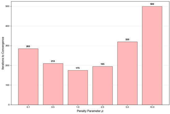
Figure 12.
Effects of Penalty Parameters on Convergence Speed.
Figure 13 compares the impact of three initialization strategies on the convergence performance of the algorithm. Zero initialization requires 175 iterations, reducing the average initialization to 168 iterations, while the best initialization based on historical data only requires 162 iterations. Although the number of iterations for different initialization strategies varies, all strategies can converge to the same optimal solution, proving the insensitivity of the algorithm to initial conditions.
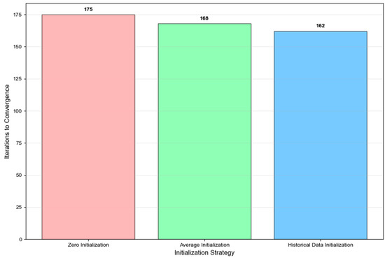
Figure 13.
Convergence performance of different initialization strategies.
Figure 14 compares the trend of actual iteration times with theoretical linear growth, verifying the scalability of the algorithm. The actual number of iterations increased from 175 for 3 microgrids to 310 for 20 microgrids, far below the theoretical linear growth expectation. Specifically, the system size increased by 6.67 times, but the number of iterations only increased by 1.77 times, showing a clear sub linear growth characteristic. This excellent scalability proof algorithm is applicable to large-scale multi-island microgrid systems and provides a theoretical basis for practical engineering applications.
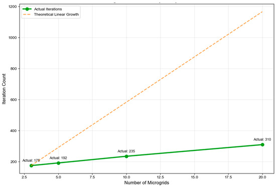
Figure 14.
Analysis of Algorithm Scalability.
6. Conclusions
This paper has proposed a hierarchical distributed energy management strategy for multi-island microgrids based on the ADMM algorithm. The proposed strategy demonstrates both economic and technical advantages: it reduces total operating costs by 10.3% compared to centralized management while maintaining privacy protection through limited information exchange of only boundary variables and DLMP signals. The algorithm exhibits good scalability with sublinear growth in iteration counts (175 to 310 iterations for 3 to 20 microgrids) and practical computation times (45.2 to 420.7 s) suitable for day-ahead scheduling applications. These results validate the method’s effectiveness in coordinating multiple island microgrids while addressing key practical concerns of economics, privacy, and computational feasibility. Future work will focus on robust optimization under extreme conditions and dynamic pricing mechanisms for enhanced cross-island energy coordination.
Author Contributions
J.S.: Formal analysis and writing–original draft. H.X.: Investigation, resources, and writing–original draft. K.Y.: Software. Y.X.: Writing–review and editing. H.Q.: Methodology and visualization. L.W.: Supervision and validation. All authors have read and agreed to the published version of the manuscript.
Funding
This work is supported by the Science and Technology Project of State Grid Zhejiang Electric Power Co., Ltd. (B311WZ23000C).
Data Availability Statement
The data in this paper comes from China State Grid and is not allowed to be disclosed due to privacy protection.
Conflicts of Interest
All authors are employed by State Grid Wenzhou Power Supply Company and have no conflicts of interest.
References
- Saeed, M.H.; Fangzong, W.; Kalwar, B.A.; Iqbal, S. A Review on Microgrids’ Challenges & Perspectives. IEEE Access 2021, 9, 166502–166517. [Google Scholar] [CrossRef]
- Altaf, M.W.; Arif, M.T.; Islam, S.N.; Haque, M.E. Microgrid Protection Challenges and Mitigation Approaches–A Comprehensive Review. IEEE Access 2022, 10, 38895–38922. [Google Scholar] [CrossRef]
- Yoldas, Y.; Onen, A.; Alawasa, K.; El Haffar, A.; Ahshan, R.; Islam, R.; Muyeen, S.; Noorfatima, N.; Jung, J. A Framework-Based Multi-Agent Coordination for Enhanced Microgrid Energy Management at the Secondary Control Layer. IEEE Trans. Appl. Supercond. 2024, 34, 5403005. [Google Scholar] [CrossRef]
- Tofighi-Milani, M.; Fattaheian-Dehkordi, S.; Gholami, M. A Novel Distributed Paradigm for Energy Scheduling of Islanded Multiagent Microgrids. IEEE Access 2022, 10, 83636–83649. [Google Scholar] [CrossRef]
- Liu, G.; Ollis, T.B.; Ferrari, M.F. Distributed Energy Management for Networked Microgrids Embedded Modern Distribution System Using ADMM Algorithm. IEEE Access 2023, 11, 102589–102604. [Google Scholar] [CrossRef]
- Li, S.; Cao, D.; Hu, W.; Huang, Q.; Chen, Z.; Blaabjerg, F. Multi-energy management of interconnected microgrids using multi-agent deep reinforcement learning. J. Mod. Power Syst. Clean Energy 2023, 11, 1606–1617. [Google Scholar] [CrossRef]
- Mishra, S.; Peterson, K.; Hilimon, T.; Shuvalova, J.; Wen, F.; Palu, I. Resiliency oriented control of a smart microgrid with photovoltaic modules. Glob. Energy Interconnect. 2021, 4, 441–452. [Google Scholar] [CrossRef]
- Wang, R.; Sun, Q.; Hu, W.; Zhang, H.; Wang, P. Power flow calculation of new power system for carbon peaking and carbon neutralization. J. Glob. Energy Interconnect. 2022, 5, 439–446. [Google Scholar]
- Xu, J.Z.; Yi, Y.Q. Multi-microgrid low-carbon economy operation strategy considering both source and load uncertainty: A Nash bargaining approach. Energy 2023, 263, 125712. [Google Scholar] [CrossRef]
- Chen, X.; Zhai, J.Y.; Jiang, Y.N.; Ni, C.; Wang, S.; Nimmegeers, P. Decentralized coordination between active distribution network and multi-microgrids through a fast decentralized adjustable robust operation framework. Sustain. Energy Grids Netw. 2023, 263, 125712. [Google Scholar] [CrossRef]
- Liu, Y.; Li, X.L.; Liu, Y.M. A Low-Carbon and Economic Dispatch Strategy for a Multi-Microgrid Based on a Meteorological Classification to Handle the Uncertainty of Wind Power. Sensors 2023, 34, 101068. [Google Scholar] [CrossRef] [PubMed]
- Chakraborty, A.; Ray, S. Multi-Objective Operational Cost Management with Minimum Net Emission of a Smart Microgrid. Electr. Power Compon. Syst. 2024, 52, 1870–1891. [Google Scholar] [CrossRef]
- Lou, H.; Fujimura, S. ADMM-Based Distributed Algorithm for Energy Management in Multi-Microgrid System. IEEE Trans. Electr. Electron. Eng. 2024, 1, 19–25. [Google Scholar] [CrossRef]
- Huang, L.; Sun, W.; Li, Q.Y.; Li, W.T. Distributed real-time economic dispatch for islanded microgrids with dynamic power demand. Appl. Energy 2023, 342, 121156. [Google Scholar] [CrossRef]
- Borghei, M.; Ghassemi, M. A Multi-Objective Optimization Scheme for Resilient, Cost-Effective Planning of Microgrids. IEEE Access 2020, 8, 206325–206341. [Google Scholar] [CrossRef]
- Cao, Y.; Li, D.; Zhang, Y.; Tang, Q.; Khodaei, A.; Zhang, H.; Han, Z. Optimal Energy Management for Multi-Microgrid Under a Transactive Energy Framework with Distributionally Robust Optimization. IEEE Trans. Smart Grid 2020, 1, 13–20. [Google Scholar] [CrossRef]
- Shirsat, A.; Muthukaruppan, V.; Hu, R.; Paduani, V.D.; Xu, B.; Song, L.; Li, Y.; Lu, N.; Baran, M.; Lubkeman, D.; et al. A Secure and Adaptive Hierarchical Multi-Timescale Framework for Resilient Load Restoration Using a Community Microgrid. IEEE Trans. Sustain. Energy 2023, 14, 1057–1075. [Google Scholar] [CrossRef]
- Hematian, H.; Askari, M.T.; Ahmadi, M.A. Robust Optimization for Microgrid Management with Compensator, EV, Storage, Demand Response, and Renewable Integration. IEEE Access 2024, 12, 73413–73425. [Google Scholar] [CrossRef]
- Habib, H.U.R.; Subramaniam, U.; Waqar, A.; Farhan, B.S.; Kotb, K.M.; Wang, S. Energy Cost Optimization of Hybrid Renewables Based V2G Microgrid Considering Multi Objective Function by Using Artificial Bee Colony Optimization. IEEE Access 2020, 8, 62076–62093. [Google Scholar] [CrossRef]
- Swief, R.A.; El-Amary, N.H.; Kamh, M.Z. Optimal Energy Management Integrating Plug in Hybrid Vehicle Under Load and Renewable Uncertainties. IEEE Access 2020, 8, 176895–176904. [Google Scholar] [CrossRef]
Disclaimer/Publisher’s Note: The statements, opinions and data contained in all publications are solely those of the individual author(s) and contributor(s) and not of MDPI and/or the editor(s). MDPI and/or the editor(s) disclaim responsibility for any injury to people or property resulting from any ideas, methods, instructions or products referred to in the content. |
© 2025 by the authors. Licensee MDPI, Basel, Switzerland. This article is an open access article distributed under the terms and conditions of the Creative Commons Attribution (CC BY) license (https://creativecommons.org/licenses/by/4.0/).