Article

Low-Power Radix-22 FFT Processor with Hardware-Optimized Fixed-Width Multipliers and Low-Voltage Memory Buffers

Department of Electrical Engineering and Information Technologies, University of Naples Federico II, Via Claudio, 21, I-80125 Naples, Italy
*
Author to whom correspondence should be addressed.
Electronics 2025, 14(21), 4217; https://doi.org/10.3390/electronics14214217
Submission received: 1 October 2025 / Revised: 25 October 2025 / Accepted: 27 October 2025 / Published: 28 October 2025

Abstract

In this paper, we propose a novel low-power implementation of the radix-22 Fast Fourier Transform (FFT) processor that exploits optimized multiplications and low-voltage memory buffers. The FFT computation requires complex products between input samples and precomputed coefficients, known as twiddle factors, as well as a large number of memory elements to store intermediate signals. To reduce power consumption, we bypass multiplications when twiddle factors are equal to zero or one. Furthermore, we introduce a fixed-width technique that lowers multiplier complexity for non-trivial coefficients by pruning the least significant columns of the partial product matrix and discarding the most significant partial products with low activation probability. To further minimize power consumption, we lower the supply voltage of memory buffers, creating two power domains in the design. Post-synthesis analysis in 28 nm technology shows that the proposed FFT achieves superior SNR and MSE compared to existing implementations, with reductions of 33% in power consumption and 30% in the power-delay product. In an OFDM receiver, the design also achieves optimal bit error rate performance under various levels of channel noise.

1. Introduction

Discrete Fourier Transformation (DFT) is a well-known mathematical operation that finds widespread employment in several digital signal processing algorithms, allowing the elaboration of signals in the frequency domain rather than in the time or spatial domain. Among possible applications, DFT constitutes the core operation in real-time spectrum analysis, video broadcasting, cryptography, mobile digital communication, and neural networks [1,2,3,4,5,6]. For example, the work [3] proposes a cooperation between DFT and Convolutional Neural Networks to enhance speech quality, as well as [4,5] exploit domain transformation to reduce the computational complexity in convolution-based algorithms. Similarly, a DFT with a tunable number of points is proposed in [6], which can define signal bandwidth in LTE and WiMAX communication systems.
The computation of the Fourier transform requires a large number of multipliers. Since these circuits occupy significant silicon area and dissipate considerable power, the hardware implementation of the DFT is particularly challenging. The use of complex arithmetic, necessary to process both the real and imaginary parts of the signals, further increases design complexity. In addition, the memory elements needed to store intermediate signals during the transformation impose a substantial burden on hardware resources due to their large storage requirements. Consequently, developing effective design strategies to mitigate the impact of multipliers and memory on overall hardware performance is essential to satisfy system constraints.
Fast Fourier Transform (FFT) algorithm constitutes a valuable solution to implement DFT in hardware, enabling the computation of an N-point DFT with a set of P-point DFTs, having P < N. Each P-point DFT, featuring feasible hardware complexity, implements the so-called butterfly that constitutes the arithmetic engine of the transformation algorithm [7,8]. Among possible architectures like Multi-path and Single-path Delay Commutators, the Single-path Delay Feedback (SDF) approach is largely preferred for the hardware realization of FFT, as it involves reduced memory, affordable arithmetic structures, and simple data flow [9]. Moreover, selecting the proper butterfly topology is also important to achieve the desired performance, since it determines the number of arithmetic operations and the kind of utilization. For instance, the radix-2 butterfly has a simple architecture, but calls for a large number of multipliers to compute the overall transformation. Additionally, arithmetic circuits involved in the computation are inactive for half the time required to produce the transformed signal, resulting in an inefficient usage of multipliers and adders. Conversely, butterflies with higher radixes employ a lower number of products and also improve the utilization time of arithmetic circuits, but pose at the same time signal congestion issues [10]. Among these, architectures like the radix-22 offer a valid compromise, being able to reduce both the number of multipliers and the routing complexity of the circuit [11,12].
Approximate Computing techniques, which improve performance in computation-intensive systems like digital filters and neural networks [13,14,15], have been recently extended also to the FFT design, providing the option to adopt inexact calculations to reduce power consumption and area occupation [16,17]. Specifically, multipliers mainly benefit from the employment of approximate implementations. For example, the work [18] proposes to downsize multipliers by selecting the most significant parts of the inputs for the product, starting from the leading one bit. At the same time, papers [19,20] simplify the selection scheme, considering only a subset of predefined segments. The paper [20] finds the optimal location for the most significant segments that can minimize the approximation error, while [21] extends the approach to the design of multiply-accumulate units. At the same time, hardware improvements are achieved by following a different approach in [22,23,24,25], where approximate compressors sum up the rows in the partial product matrix (PPM) of the multiplier. As a further example, ref. [26] truncates the least-significant columns of the PPM, while [27,28] exploit encoding techniques to realize multiplications with shift-and-add operations.
Regarding the application of approximate arithmetic circuits in the FFT, the paper [29] exploits inexact Booth multipliers with customized 4-2 compressors for a radix-4 FFT implementation, while [30] investigates the effects of approximate adders like [31,32] on precision and hardware results. The paper [33] devises the usage of multipliers [18,27,28] for a radix-2 butterfly, exploiting dynamic segmentation and approximate encoding, and also proposes a customized architecture in which only a butterfly is shared among several stages of the SDF FFT. In [34], the authors address finite word-length effects on overall precision, proposing an algorithm that defines the bit-width of signals as a function of the SDF stage.
From the memory perspective, designing circuits with high storage capacity while maintaining optimal power and area efficiency requires careful consideration. Static Random-Access Memories (SRAM) represent a common solution for compact memory implementation with favorable hardware characteristics. However, their integration is often challenging due to reliance on technology-dependent macros provided by foundries. Alternatively, several works [35,36,37,38] propose implementing memories using standard cells. In such cases, latches or flip-flops are employed, enabling simpler integration strategies but typically resulting in suboptimal area and power efficiency.
In this paper, we propose a novel approximate radix-22 SDF FFT processor with hardware-efficient multiplications and low-power memory. The computation of the transformed signal requires the multiplication of the input samples and a set of coefficients defined at design time. Moreover, samples computed in the stages of the SDF algorithm need to be continuously stored in memory for subsequent elaborations, leading to high power dissipation. To improve performance, we first introduce a multiplexing scheme that skips multiplication when coefficients are equal to zero or one. This way, the switching activity of signals in multipliers is lowered, leading to a reduction in power dissipation. At the same time, a voltage-scaling approach is exploited to implement memory elements of the circuit with the aim of minimizing their impact on overall performance.
To further reduce power dissipation, we also approximate the design of multipliers, proposing a novel fixed-width technique to perform the product when the coefficients are non-trivial. In our approach, first, an intensive approximation is applied to the least significant part of the multiplier PPM, discarding its columns. Secondly, a finer approximation is used for the most significant part, where only partial products with a low probability of being one are dropped. Additionally, probability information is suitably exploited to find the optimal number of deleted terms in each row of the PPM. Then, two parameters define the multiplier architecture, which are the number of truncated columns and the number of pruned most significant partial products.
It is worth noting that our study is based on a thorough circuit-level analysis and quantitative validation of both the arithmetic and memory sections, enabling the identification of an optimal radix-22 FFT implementation. The proposed techniques—such as multiplier approximation, coefficient skipping, and memory voltage scaling—collectively achieve up to a 33% reduction in power consumption compared to state-of-the-art designs, while preserving high accuracy.
The proposed circuit is synthesized in TSMC 28 nm CMOS technology and compared with state-of-the-art designs in order to highlight accuracy and hardware achievements. Error analyses reveal the possibility of having configurable precision, measured in terms of Signal-to-Noise Ratio (SNR) and Mean Squared Error (MSE), which depends on the number of columns and close-to-zero partial products dropped in the multipliers. Hardware results also show substantial improvements with respect to other implementations (which only approximate arithmetic sections in the FFT, like in [29,33]), offering power saving up to 33%. Investigated FFTs are also employed in an Orthogonal Frequency-Division Multiplexing (OFDM) receiver. Again, results highlight the potential of our proposal, which achieves a valuable bit error rate (BER) under several noise levels.
The paper is organized as follows: Section 2 offers an overview of the radix-22 FFT processors, while Section 3 describes the proposed low-power technique. In Section 4, accuracy and hardware results are shown, as well as the behavior in the OFDM receiver is presented. Section 5 summarizes the main findings, highlighting the trade-off between hardware improvement and precision. Then, Section 6 concludes the paper.

2. Radix-22 FFT Processor

Let us consider the sequence x(n), expressed on N points, and the relative transformation X(k), with n and k lying in the range [0, N − 1]. The N-point DFT of x(n) is computed as follows:
X ( k ) = n = 0 N 1 x ( n ) · e j 2 π n k N     = n = 0 N 1 x ( n ) · W N n k
with W N = e j 2 π N that is the so-called twiddle factor. As observed from (1), the DFT requires N complex multiplications for each value of k. Therefore, the overall number of complex products needed to compute (1) is N2, corresponding to 4·N2 real multiplications.
To simplify the algorithm, indices n, k can be factorized to reduce the number of products. The type of factorization affects the architecture of the overall circuit, determining the structure of butterfly blocks. In the case of the radix-22 implementations and focusing the attention on a 256-point DFT, considered in the rest of the paper, the following expression is used for indices n, k:
n = 128 n 1 + 64 n 2 + n 3 ,         k = k 1 + 2 k 2 + 4 k 3
with n1, n2, k1, k2 = 0, 1 and n3, k3 = 0, 1, …, 63. In general, indices are written in the form n = (N/2)·n1 + (N/4)·n2 + n3 and k = k1 + 2k2 + 4k3, with n3, k3 = 0, 1, …, (N/4) − 1.
Substituting the above expression in (1) for N = 256, the DFT becomes
X ( k ) = n 3 = 0 63 n 2 = 0 1 n 1 = 0 1 x ( 128 n 1 + 64 n 2 + n 3 ) · W 256 ( 128 n 1 + 64 n 2 + n 3 ) ( k 1 + 2 k 2 + 4 k 3 )
The twiddle factor in (3) can be written as
W 256   ( 128 n 1 + 64 n 2 + n 3 ) ( k 1 + 2 k 2 + 4 k 3 ) = ( 1 ) n 1 k 1 ( j ) n 2 ( k 1 + 2 k 2 ) W 256 n 3 ( k 1 + 2 k 2 ) W 64 n 3 k 3
after simple algebra, having considered the following properties:
W 256 128 n k = ( 1 ) n k W 256 64 n k = ( j ) n k W 256 A n k = 1 W 256 4 n k = W 64 n k
with A that is an integer multiple of N = 256.
Then, substituting (4) in (3) and dividing the summation for indices n1, n2, and n3, the following terms are highlighted:
B F 1 ( n 2 , n 3 ) = n 1 = 0 1 x ( 128 n 1 + 64 n 2 + n 3 ) · ( 1 ) n 1 k 1 = x ( 64 n 2 + n 3 ) + ( 1 ) k 1 · x ( 128 + 64 n 2 + n 3 )
B F 2 ( n 3 ) = n 2 = 0 1 B F 1 ( n 2 , n 3 ) · ( j ) n 2 ( k 1 + 2 k 2 ) = B F 1 ( 0 , n 3 ) + ( j ) k 1 + 2 k 2 · B F 1 ( 1 , n 3 )
X ( k ) = n 3 = 0 63 B F 2 ( n 3 ) · W 256 n 3 ( k 1 + 2 k 2 ) W 64 n 3 k 3
As is observable, the transformed signal X(k) is computed starting from Equations (6) and (7), which determine the butterflies’ architecture in the radix-22 FFT processor. Then, the obtained results are further combined with the twiddle factors as shown in (8). In each butterfly, only complex additions and trivial multiplications are performed. Indeed, the term (−1)k1 in (6) merely calls for a sign inversion, as well as the term (−j)k1+2k2 in (7) only demands a swap between real and imaginary parts. On the other hand, products with twiddle factors in (8) are non-trivial, determining the employment of binary multipliers.
In addition, it is worth noting that the summation in (8) corresponds to the 64-point DFT of the quantity BF2(n3 W 256 n 3 ( k 1 + 2 k 2 ) . This observation suggests that the DFT can be iteratively factorized until no further decompositions are possible, having 64-point, 16-point, and 4-point DFTs in our case. Twiddle factors for 64 and 16-point DFTs are in the form W 64 n 3 2 ( k 1 2 + 2 k 2 2 ) , W 16 n 3 3 ( k 1 3 + 2 k 2 3 ) , respectively, with apex i on factorized indices that indicate the iteration number. At the same time, twiddle factors equal 1 for the 4-point DFT.
The SDF block diagram of the 256-point radix-22 FFT is represented in Figure 1a. As shown, the processor exhibits a modular structure, with each module emerging from a decomposition step. Each factorization requires (i) a complex multiplier (highlighted in red) and (ii) the butterflies BF1, BF2, whose inner structure is detailed in Figure 1b,c. As is observable, a simple multiplexer is used to perform trivial multiplications. In addition, ROM memories are also implemented to store non-trivial values of twiddle factors, and a state counter acts as a control circuit to configure butterflies and ROM outputs. Figure 1a also highlights the presence of memory buffers in each module (see the violet dashed box), whose task is to store the samples computed by the butterflies during the transformation.
In the following, the input sequence x(n), the output X(k), and twiddle factors are supposed to be on 16 bits, while the outputs of butterflies BF1, BF2, after the first decomposition, are expressed on 17 and 18 bits, respectively, to prevent overflow. Consequently, an 18 × 16 complex multiplier is employed in the first module. Additionally, the output is also truncated to 18 bits to reduce circuit complexity in the following stages. With similar reasoning, we obtain butterfly outputs on 19 and 20 bits, followed by a 20 × 16 multiplier in the second module, and signals on 21 and 22 bits, followed by a 22 × 16 multiplier in the third iteration. Then, three complex multiplications are required for the 256-point radix-22 FFT, corresponding to 12 real multipliers, and large buffers are also required to store computed samples. Since the size of multipliers and buffers is relevant, the adoption of optimal design strategies aimed at reducing area occupation and power consumption is of primary importance to improve circuit performance in the FFT processor.

3. Hardware Implementation

3.1. Multiplication with Trivial Coefficients

To describe the proposed technique, let us focus our attention on the third decomposition step. In this iteration of the algorithm, signals are elaborated as in a 16-point DFT with the following index factorization:
n 3 = 8 n 1 3 + 4 n 2 3 + n 3 3 ,     k 3 = k 1 3 + 2 k 2 3 + 4 k 3 3
where n 3 3 , k 3 3 = 0, 1, 2, 3, and the other terms vary between 0 and 1.
Moreover, let us call BF2,Re, BF2,Im the real and the imaginary parts of the signal computed by the butterfly BF2, so that
B F 2 ( n 3 3 ) = B F 2 , Re ( n 3 3 ) + j B F 2 , Im ( n 3 3 )
and let us consider the Euler representation for W 16 n 3 3 ( k 1 3 + 2 k 2 3 )
W 16 n 3 3 ( k 1 3 + 2 k 2 3 ) = e j 2 π n 3 3 ( k 1 3 + 2 k 2 3 ) 16 = cos ( 2 π n 3 3 ( k 1 3 + 2 k 2 3 ) 16 ) j sin ( 2 π n 3 3 ( k 1 3 + 2 k 2 3 ) 16 )
Using (10) and (11), the multiplication with the twiddle factor becomes
B F 2 ( n 3 3 ) · W 16 n 3 3 ( k 1 3 + 2 k 2 3 ) = B F 2 , Re ( n 3 3 ) + j B F 2 , Im ( n 3 3 ) · cos ( 2 π n 3 3 ( k 1 3 + 2 k 2 3 ) 16 ) j sin ( 2 π n 3 3 ( k 1 3 + 2 k 2 3 ) 16 ) = B F 2 , Re ( n 3 3 ) · cos ( 2 π n 3 3 ( k 1 3 + 2 k 2 3 ) 16 ) + B F 2 , Im ( n 3 3 ) · sin ( 2 π n 3 3 ( k 1 3 + 2 k 2 3 ) 16 ) + j B F 2 , Im ( n 3 3 ) · cos ( 2 π n 3 3 ( k 1 3 + 2 k 2 3 ) 16 ) B F 2 , Re ( n 3 3 ) · sin ( 2 π n 3 3 ( k 1 3 + 2 k 2 3 ) 16 )
The above equation highlights that the butterfly output is multiplied by sine and cosine terms whose arguments are defined by the indices n 3 3 , k 1 3 , k 2 3 .
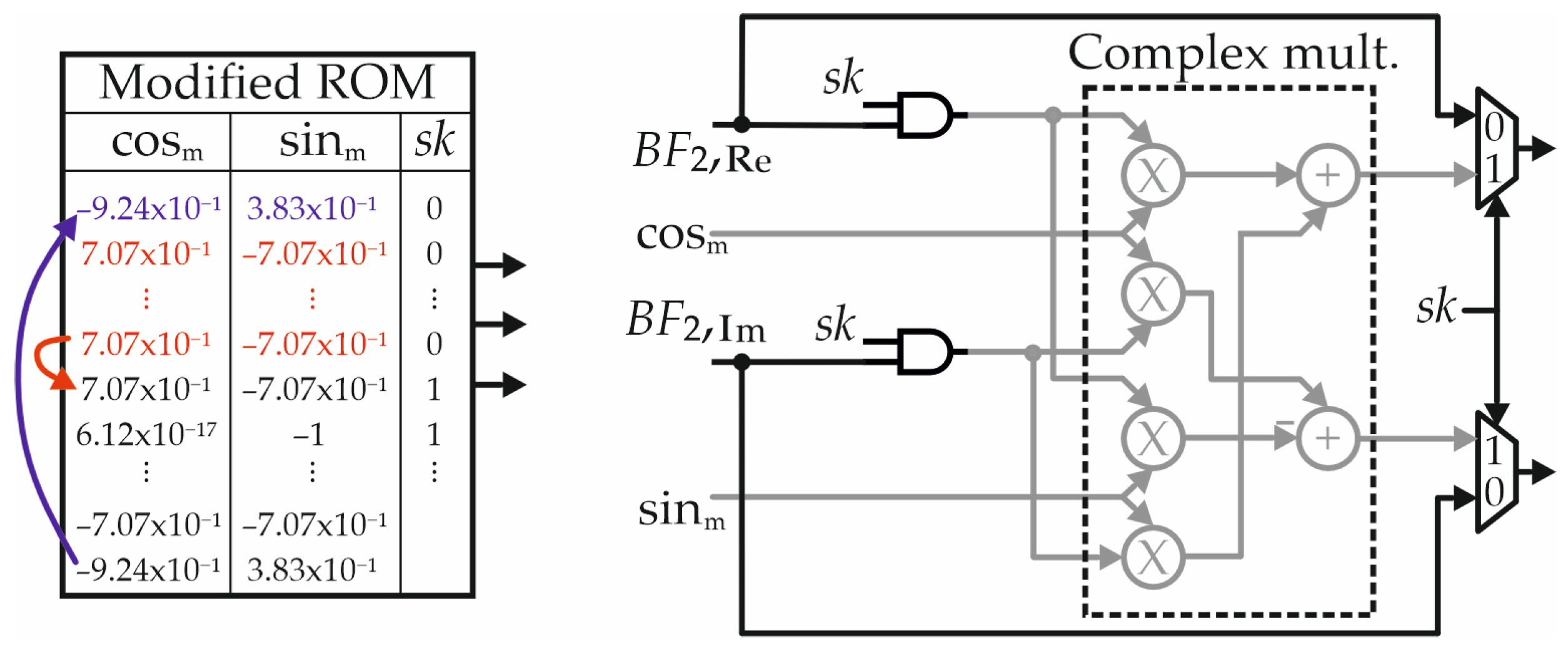
Table 1 shows the real and imaginary parts of W 16 n 3 3 ( k 1 3 + 2 k 2 3 ) stored in the ROM, with sine and cosine values that are represented with two digits after the point for the sake of simplicity. Moreover, indices n 3 3 , k 1 3 , k 2 3 are also reported for the sake of clarity. As observable, the index n 3 3 is zero when the ROM address varies between 0 and 4, determining zero argument for sine and cosine functions (see the table for reference). Accordingly, in such cases real and imaginary parts of the twiddle factor assume values that are one and zero, respectively, calling for five consecutive trivial multiplications.
The above observation suggests (i) skipping the multiplication in the mentioned cases, and (ii) directly selecting the term BF2,Re for the real part of the product and BF2,Im for the imaginary part of the product (see also (12)). Similarly, the same approach can be applied to the first and second modules of the SDF, finding that twiddle factors exhibit 65 and 17 trivial values, respectively.
Figure 2 depicts the skipping logic used to perform trivial multiplications. As shown, the ROM is augmented by one bit to output the state flag sk, which allows the identification of trivial products. Specifically, sk is kept low for addresses between 0 and 4, as also indicated in Table 1, whereas it is kept high in the other cases. Then, a couple of multiplexers are suitably configured to output BF2,Re, BF2,Im when sk = 0, bypassing multiplications. To reduce the switching activity, AND gates are also employed to hold BF2,Re, BF2,Im at zero at the input of the complex multiplication (highlighted in gray), thus lowering the power consumption of multipliers and adders. In relation to this, the ROM content is also modified as shown in Figure 2 to further minimize signal commutations when the circuit enters and exits from the skipping condition. To this aim, we impose that the first values of sine and cosine are equal to the last values stored in the ROM, highlighted in blue in the figure. This way, when the FFT enters the skipping condition, only BF2,Re, BF2,Im vary (as they are gated) while sine and cosine terms are kept constant, thus reducing glitches in the multipliers. With a similar approach, remaining values of sine and cosine are set to the first non-trivial values, highlighted in red, so that only BF2,Re, BF2,Im vary when the circuit exits from the skipping condition.

3.2. Proposed Fixed-Width Multiplier

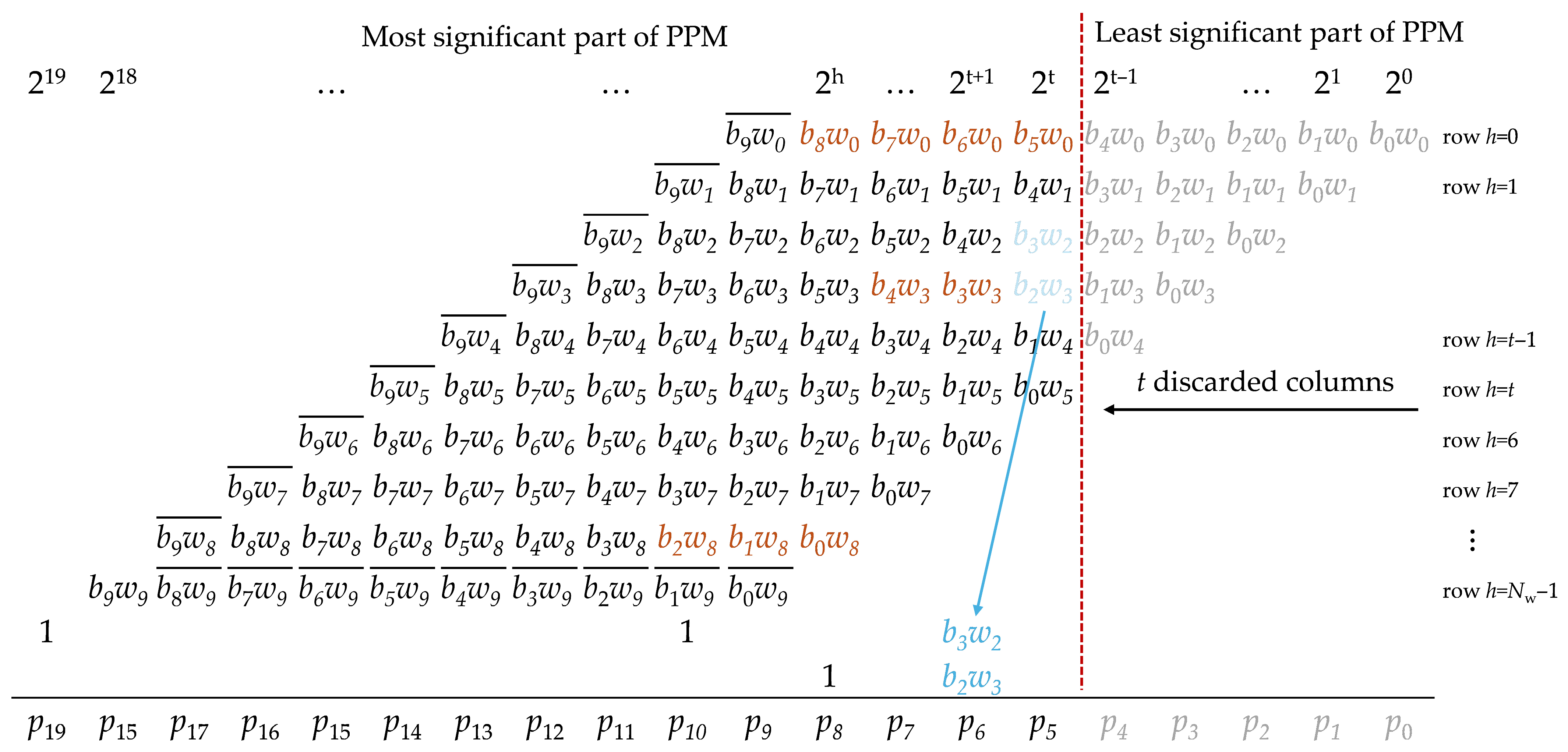
Even though the skipping method allows for bypassing multiplications in trivial cases, the number of non-trivial products required to compute the transformed signal is still high and calls for careful analysis. To improve performance in this case, we have adopted a fixed-width design methodology. The structure of the proposed multiplier is depicted in Figure 3, where a 10 × 10 multiplier is taken for reference for the sake of demonstration. As shown, the PPM is divided into two parts, gathering the most significant and the least significant columns, respectively. In the least significant part, we discard the t columns, highlighted in gray, introducing an error in the computation. To recover accuracy, the central partial products of the first preserved column, colored in blue, are double weighted following the correction technique proposed in [26], so that the mean square error of the approximation is minimized.
In the most significant part of the PPM, we follow a finer approach in order to further alleviate hardware burden while preserving acceptable levels of accuracy.
To begin with, it is worth noting that twiddle factor values are defined at design time and that the probability of having a high partial product is computed as follows:
P ( p i h ) = P ( b i w h ) = P ( b i ) · P ( w h )
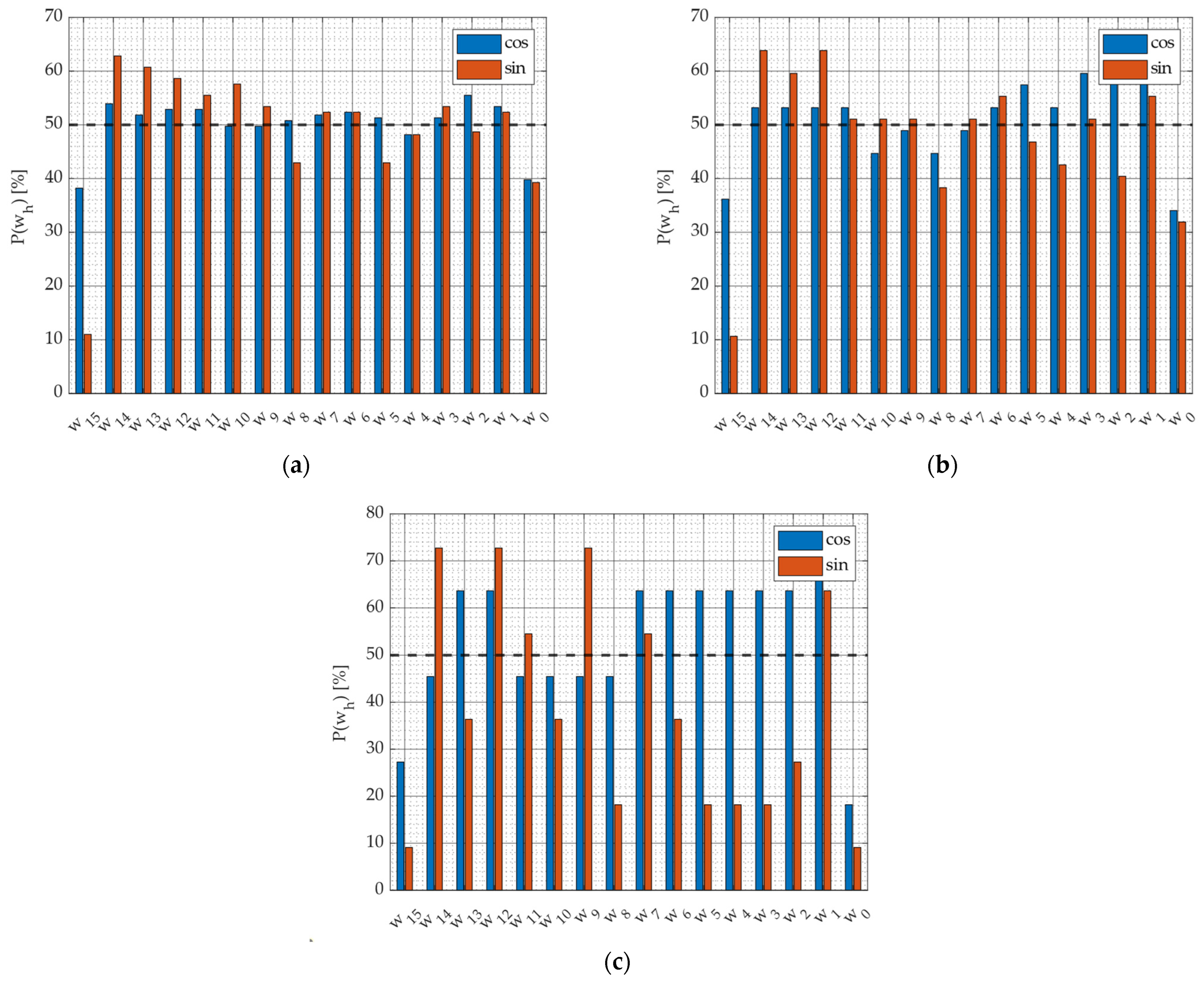
with bi that is the i-th bit of the real (or imaginary) part of the signal at the output of the butterflies BF2, and wh that is the h-th bit of the real (or imaginary) part of the twiddle factor. Please note that bits bi and wh are supposed to be independent in (13). Moreover, let us also consider P(bi) = 50% for the sake of demonstration. Since twiddle factors are known at design time, we can compute the probability P(wh) that a generic bit wh is high. Figure 4 depicts the values of P(wh) for the sine and cosine components of twiddle factors in the first, second, and third modules.
The differences observed among the probability diagrams in Figure 4a–c arise from the distinct values of the twiddle factors employed in each FFT stage. These coefficients depend on the factorized indices defined by the radix-22 decomposition and therefore vary from one stage to another.
Due to the large number of twiddle factors involved in a 256-point FFT, a purely analytical prediction of these bit probabilities is not straightforward. For this reason, we adopted a simulation-based approach to estimate the probability of each bit being ‘1’. This method is fully justified, as all twiddle factors are known at design time, and it provides the precise information required to identify which partial products in the multipliers’ partial product matrix (PPM) can be safely neglected without significantly affecting accuracy.
The dashed black line highlights the probability level of 50%, taken as a reference. The figure points out that some bits are high with low probability, making room for approximation. For example, bits w13, w10, w8, w6, w5, w4, w3, w2, w0 of the sine in Figure 4c exhibit P(wh) less than 40%, with w0 showing the lowest probability (less than 10%). Supposing to have P(bj) = 50%, the probability of having bjw0 = 1 is lower than 5%. Accordingly, partial products of the kind bjw0 can be truncated to gain hardware performance without dramatically degrading the accuracy of results. Similarly, bits w14, w11, w10, w9, w8, w0 of cosine are worth attention, as well as the central bits of sine and cosine in Figure 1a,b.
In our approach, we define the number of truncated partial products as a function of the bit probability P(wh) to properly balance the trade-off between hardware improvement and multiplier accuracy. The rationale behind our idea is to apply a more aggressive truncation in rows where P(wh) is lower, and a lighter approximation in rows where P(wh) is higher. Figure 3 clearly shows the above concept, supposing that P(w0) < P(w8) < P(w3). Here, the row of w0 exhibits the maximum number of deleted terms (up to 5, depicted in brown), while a lower number of partial products is discarded in the other cases.
Additionally, it is also worth noting that the rows have different weights in the PPM as some of them are left-shifted, as clearly pointed out in Figure 3. Accordingly, the number of pruned terms should be chosen by taking into account the weight assumed by partial products, since it also affects the approximation error.
To define the amount of truncation, we first divide the multiplier rows into three groups based on the weight of their least significant bit (LSB). In the following, we refer to h as the row index, for h = 0, 1,… Nw − 1, with Nw being the number of bits of sine and cosine coefficients. Then, referring to Figure 3, we have that:
(i)
rows for h < 2 and tht + 1 have LSB of weight 2t;
(ii)
rows for 2 ≤ h < t have LSB of weight is 2t+1;
(iii)
rows for h > t + 1 the LSB weighs 2h.
Moreover, the approximation is applied when the probability that the wh of the partial product is high is lower than a predefined threshold, named Ptarget in the following.
When mh is the number of pruned partial products in the h-th row, the approximation error assumes the following expression:
e ( h ) = i = t t + m h 1 b i w h 2 i       f o r     h < 2     a n d     t h   t + 1     i = t + 1 t + m h b i w h 2 i             f o r     2 h < t i = h h + m h 1 b i w h 2 i       f o r     h > t + 1
while the mean error µe(h) is
μ e ( h ) = E i = t t + m h 1 b i w h 2 i         f o r     h < 2     a n d     t h   t + 1 E i = t + 1 t + m h b i w h 2 i               f o r     2 h < t E i = h h + m h 1 b i w h 2 i         f o r     h > t + 1  
Assuming that the mean operator E[·] is linear and that bi, wh are independent, (15) becomes
μ e ( h ) = i = t t + m h 1 E b i w h 2 h         f o r     h < 2     a n d     t h   t + 1 i = t + 1 t + m h E b f 2 , i w j 2 i               f o r     2 h < t i = j j + m h 1 E b i w h 2 i           f o r     h > t + 1   = E b i E w h · i = t t + m h 1 2 i         f o r     h < 2     a n d     t h   t + 1 E b i E w h · i = t + 1 t + m h 2 i               f o r     2 h < t E b i E w h · i = h h + m h 1 2 i         f o r     h > t + 1
Writing the mean value E[wj] as follows
E w h = 1 · P ( w h ) + 0 · ( 1 P ( w h ) ) = P ( w h )
and using the following relations for the summations (for details refer to the Appendix A)
i = t t + m h 1 2 i = 2 t + m h 2 t = 2 m h 1 · 2 t i = t + 1 t + m h 2 i = 2 t + m h + 1 2 t + 1 = 2 m h 1 · 2 t + 1 i = h h + m h 1 2 i = 2 h + m h 2 h = 2 m h 1 · 2 h
we obtain:
μ e ( h ) = = E b i P w h · 2 m h 1 · 2 t                     f o r     h < 2     a n d     t h t + 1 E b i P w h · 2 m h 1 · 2 t + 1             f o r     2 h < t E b i P w h · 2 m h 1 · 2 h                   f o r     h > t + 1  
As highlighted in (19), the committed error depends on both the probability P(wh) and on the number of truncated terms mh, as well as on the weight of LSBs, represented by exponential contributions 2t, 2t+1, and 2h.
Let us consider the worst-case scenario in which m partial products are truncated in the h*-th row, exhibiting the highest probability P(wh*). The mean error for this row is:
μ e ( h * ) = = E b i P max · 2 m 1 · 2 t                       f o r     h * < 2     a n d     t h * t + 1 E b i P max · 2 m 1 · 2 t + 1               f o r     2 h * < t E b i P max · 2 m 1 · 2 h *                   f o r     h * > t + 1
with Pmax = P(wh*).
To find the values of mh for other indices, we impose that each row exhibits the same approximation error as a sizing criterion. Therefore, mh is computed by solving the equality
μ e ( h ) = μ e ( h * )
for each value of h. It is worth noting that the above equation is solved only for rows where the condition P(wh) ≤ Ptarget is verified.
Table 2 reports the solution of (21) considering all possible combinations between indices h* and h. As shown, mh exhibits a logarithmic dependence with respect to the ratio Pmax/P(wj) and the parameter m. In particular, if 2m is sufficiently larger than one and the rows are in the same group, it is possible to increase mh of one with respect to m for each doubling of Pmax/P(wh).

3.3. Memory Buffer

Memory buffers also constitute an important part of the SDF FFT processor, being in charge of acquiring the input samples and of storing signals computed by the butterflies. Generally, a first-in first-out topology is adopted for their implementation to make the selection of the stored signal simple, suggesting the employment of shift registers. At the same time, each register, made up of flip-flops in the standard-cell design flow, needs to be written at each clock cycle, thus negatively affecting power dissipation. Furthermore, the demand for large storage capabilities (in the case of our FFT, 256 registers are required to store signals expressed up to 22 bits) also leads to high energy consumption for clock distribution due to high-load capacitances. To reduce the hardware impact of memory buffers, we downscale the supply voltage of shift registers with respect to the arithmetic section of the FFT processor. In addition, level shifters are added in the design to ensure proper data flow between the buffers and the arithmetic circuits, working with the nominal supply voltage.
It is worth noting that voltage scaling integrates well in the context of standard-cell-based design flow, benefiting from the adoption of well-established design methodologies, and is also a suitable candidate to reduce power dissipation in systems exhibiting high-load capacitances (as in the case of clock distribution in memory buffers).

4. Results

4.1. Accuracy Assessment

To verify the accuracy of the proposed FFT processor, we compare the approximate results with the signal transformed through the Matlab R2023b function fft, considering a 256-point random input as a test case, quantized on 16 bits. Circuit-level precision is assessed in terms of Signal-to-Noise ratio (SNR) and Mean Squared Error (MSE) between the transformed signals.
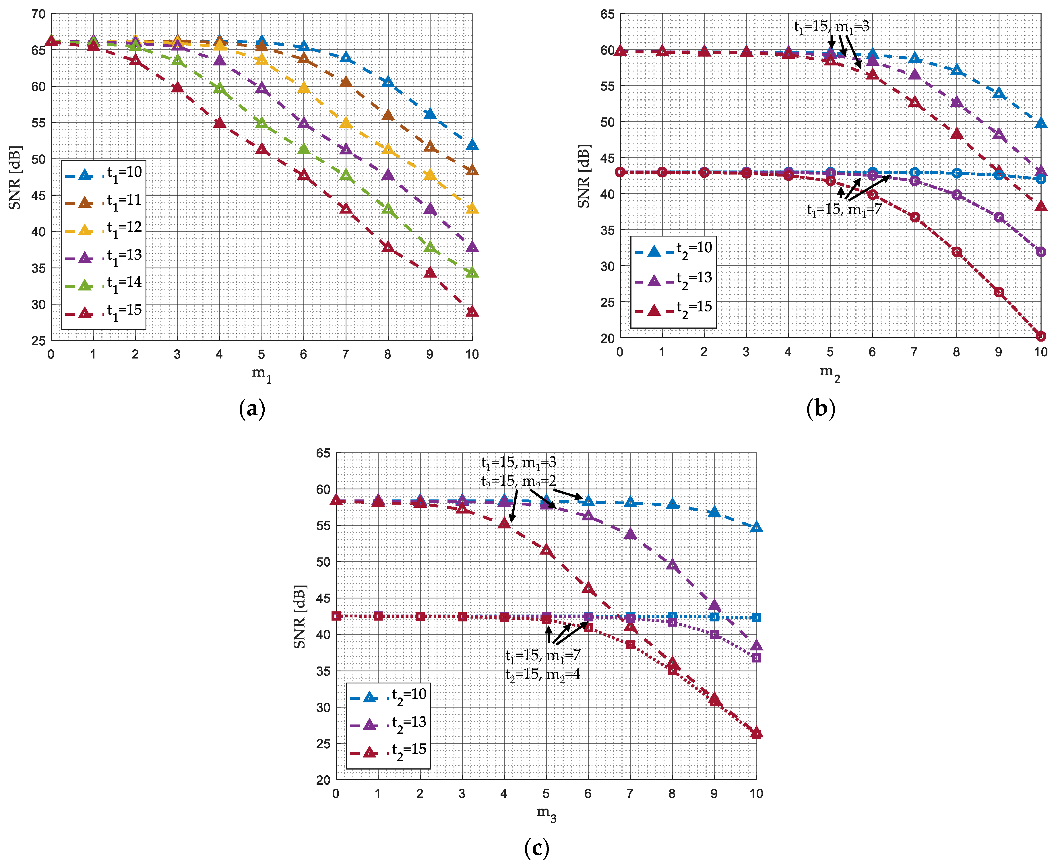
Figure 5 depicts the accuracy performance of the proposed FFT with respect to the number of truncated columns in the first, second, and third multipliers, indicated as t1, t2, and t3 respectively, and of the pruned partial products, computed in dependence on parameters m1, m2, m3, defined starting from the worst-case probability of having high bits in twiddle factors. In Figure 5a, only multipliers in the first module are approximated, while in Figure 5b, 5c we apply our fixed-width technique also to multipliers of the second and third modules, respectively. As shown, FFT accuracy depends on both t and m parameters, exhibiting a worsening of performance when the number of pruned terms increases. For example, in Figure 5a, SNR clearly decreases for t1 that ranges from 10 to 15, as well as a reduction in precision is registered for m1 approaching 10. Accuracy due to approximation in the second multiplier worsens for increasing values of t2 and m2. Moreover, the precision is also affected by the approximation of previous stages. Indeed, SNR is able to approach 60 dB if the first multiplier is approximated with t1 = 15 and m1 = 3, whereas it is limited to 44 dB if m1 = 7. Similar considerations are also valid for the approximation in the multipliers of the third module, as clearly shown in Figure 5c. On the basis of the above analysis, we truncate t = 10, 13, and 15 least significant columns in all multipliers, while the following combinations of m parameters are chosen, which lead to an advantageous trade-off between hardware results and precision: (i) m1 = 3, m2 = 2, m3 = 3, (ii) m1 = 6, m2 = 3, m3 = 4, (iii) m1 = 7, m2 = 4, m3 = 5, (iv) m1 = 8, m2 = 8, m3 = 10. We refer to these implementations as:
  • A-FFT103,2,3, A-FFT106,3,4, A-FFT107,4,5, A-FFT108,8,10;
  • A-FFT133,2,3 A-FFT136,3,4, A-FFT137,4,5, A-FFT138,8,10;
  • A-FFT153,2,3, A-FFT156,3,4, A-FFT157,4,5 A-FFT158,8,10.
It is worth noting that other possible combinations of t, m parameters can be selected so that the most appropriate accuracy and hardware performance, tailored to the target application constraints, can be achieved.
For the sake of comparison, we also follow the approach of [33], investigating the effects of approximate multipliers described in [18,27,28] for the computation of the transformed signal. In [27], shift-and-add operations are exploited to compute the product, and the sign inversion of the multiplicands, required in signed arithmetic, is computed both through a two’s-complement operation (SRoBA version of the multiplier) and a one’s-complement operation (ASRoBA version of the multiplier). Also [28], referred to as LoBA in the following, exploits signal recoding followed by truncation to reduce hardware complexity, while [18], named DRUM, applies a dynamic segmentation on inputs in order to multiply only their most significant parts. In this analysis, we consider segments expressed on 6, 7, and 8 bits, having the implementations DRUM6, DRUM7, and DRUM8. The static segmented approach of [19] is also investigated, having 14 × 8 and 14 × 12 multipliers (named SSM14,8 and SSM14,12, respectively). In this case, twiddle factors are expressed on 8 and 12 bits. Finally, multipliers with the approximate compressors of [22,23] are also considered for the FFT, named C4/2 Ahma and C4/2 Momeni, as well as the design implementing the Booth multiplier of [29], referred to as FFT-cmplx4 in the following.
Table 3 shows the precision results of the investigated FFT processors. The accuracy of the proposed circuits depends on the number of terms truncated in both the most significant and less significant parts of the PPM. For example, for t = 15, the SNR varies from 24 dB (case A-FFT158,8,10) to 57 dB (case A-FFT153,2,3), determining an improvement as the number of dropped partial products lowers in the most significant part. Similarly, the parameter t affects error metrics, determining the best accuracy with the implementation of A-FFT10. The MSE follows a similar behavior, improving up to an order of magnitude if the number of truncated terms is reduced.
FFT with C4/2 Momeni [22] is able to achieve similar performance, registering SNR of 55 dB, whereas FFT-cmplx4 [29] is the only one able to offer SNR larger than 60 dB and MSE around 5 × 10⁻⁵. Other implementations have lower precision. Implementations with DRUM and SSM exhibit a remarkable dependence of the accuracy on the segmentation scheme, showing SNR that varies in the ranges 30−42 dB and 36−52 dB, respectively. At the same time, the worst performance is achieved by SRoBA, ASRoBA, and LoBA, whose values of SNR and MSE are limited to 26 dB and 1.05 × 10⁻¹.

4.2. Hardware Results

To verify the hardware performance of the investigated circuits, we synthesize the FFT processors in TSMC 28 nm CMOS technology using Cadence Genus 18.13, with a clock frequency of 100 MHz and standard cells with nominal threshold voltage. The arithmetic sections of the proposed FFT are powered with a power supply of 0.9 V, while register buffers are supplied at 0.8 V. To this aim, we use the Common Power Format (CPF) file to define power domain directives and to add level shifters, chosen from the standard cells. The other implementations, which do not exploit power-scaling techniques for memory sections, are synthesized with a supply voltage of 0.9 V. Area occupation and critical path delay, assessed among register-to-register paths, are reported from post-synthesis analyses. Power consumption is computed through post-synthesis simulations as well, considering a 16-bit complex random noise as input. Here, the Standard Delay Format (SDF) file annotates the path delays, while the switching activity is registered through the Toggle Count Format (TCF) file. For this analysis, the standard implementation of the radix-22 processor, which exploits exact multipliers and a unique voltage domain, is taken for reference to compute area, power, and delay performance of the proposed and state-of-the-art designs.
As shown in Table 3, area reduction ranges between 2% and 7% with the implementations A-FFT13 and A-FFT15, whereas a negligible worsening is registered with A-FFT10. This behavior results from the balance between the fixed-width approach, which downsizes the multipliers, and the introduction of the skipping logic, managing trivial multiplications. Additionally, the level shifters lead to an area overhead.
Similarly, slight area improvements are achieved with C4/2 Ahma [23] and C4/2 Momeni [22], while the employment of Booth multipliers leads to higher reductions (9.6%). The best results are achieved using segmentation techniques and input recoding. Specifically, the area improves more than 18% with DRUM6 [18] and SSM14,8 [19]. On the other hand, our FFT and designs exploiting [22,23,29] offer critical path delays very close to the standard implementation, whereas other circuits exhibit lower performance. From a power perspective, our FFT is the only one able to overcome 30% of energy reduction, with A-FFT158,8,10 that achieved an improvement of about 33%. Power reduction registered with approximate compressors [22,23] and AFFT-cmplx4 [29] is minimal, whereas, among the other implementations, only LoBA [28] is able to approach an improvement of 21%.

4.3. Performance in OFDM Receiver

In addition to the circuit-level evaluation, we further validated the proposed FFT processor in a practical communication scenario. Specifically, this section presents its integration within an Orthogonal Frequency-Division Multiplexing (OFDM) receiver, serving as a system-level case study. This second analysis complements the post-synthesis results by demonstrating that the proposed low-power architecture maintains excellent bit error rate (BER) performance under various channel noise conditions, thereby confirming its applicability and reliability in real-world communication environments.
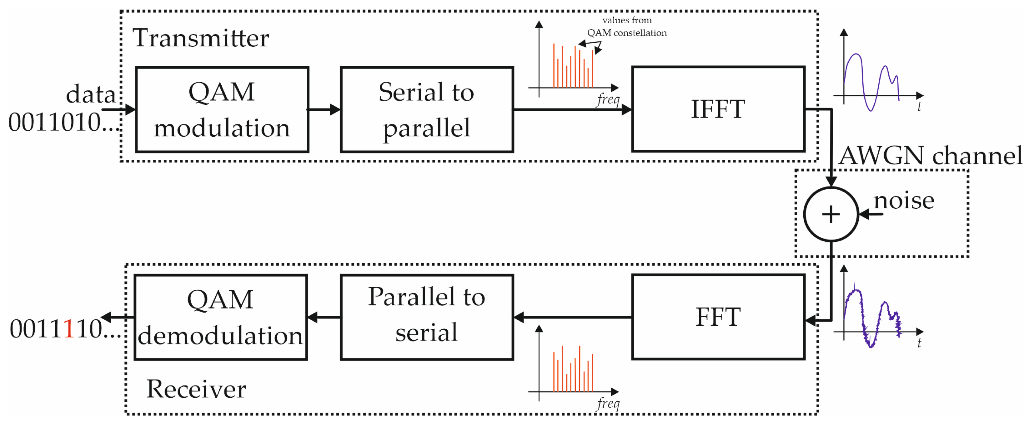
In telecommunication, Orthogonal Frequency Division Multiplexing (OFDM) is a technique widely employed for data transmission and reception, which allows for achieving high bit rates with optimal bandwidth occupation. Among different advantages, OFDM is resilient to inter-symbol interference and path fading, becoming one of the best choices for effective communication in modern transceivers. In the OFDM approach, the transmitted information is allocated to different subcarriers. Then, the receiver finds the subcarriers’ content in order to recover the desired data. Figure 6 shows a simplified block diagram representing the transmitter, the receiver, and the communication channel, modeled with Additive White Gaussian Noise. As shown, the direct and inverse Fourier transformations occupy a central role in the definition of the OFDM signal. In the transmitter, the bitstream is mapped through a digital modulation, like the Quadrature Amplitude Modulation (QAM) of Figure 6. Then, each symbol obtained from the digital modulation is placed on a subcarrier and transformed into the time domain by means of the inverse FFT (IFFT). At the same time, the FFT allows for finding the content of subcarriers in the receiver. Then, a demodulator rebuilds the bitstream starting from the received samples.
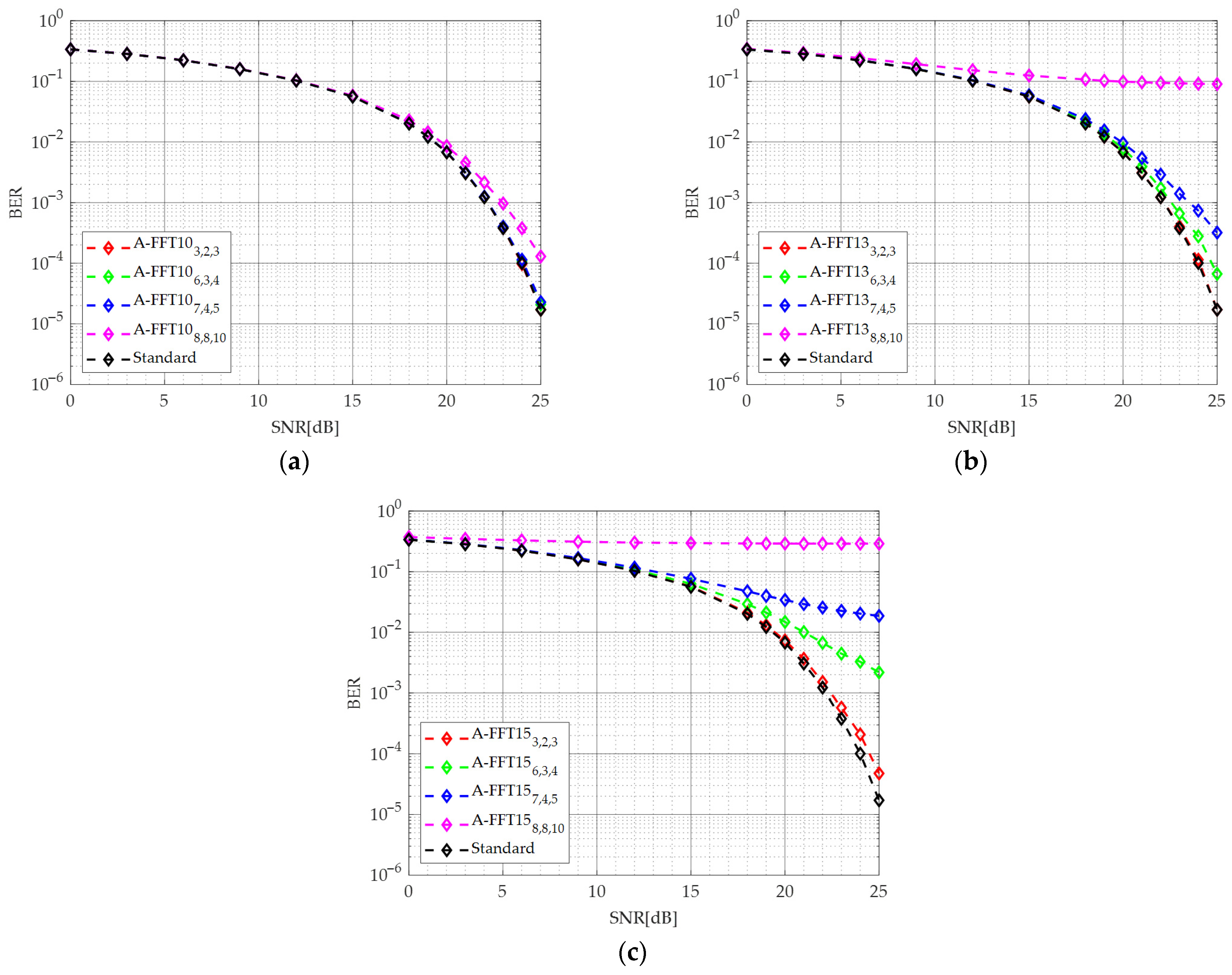
In this analysis, we studied the performance of an OFDM receiver when the investigated FFTs are employed to recover the subcarriers’ content. In this trial, the “Cameraman” image is transmitted, mapping the bitstream on a 64-QAM and distributing the obtained symbols on 208 subcarriers. The Bit Error Rate (BER), defined as the ratio between the number of incorrect bits after reception and the overall number of transmitted bits, is computed as an accuracy metric. Furthermore, several levels of channel noise are considered for our analysis, so that the OFDM signal features an SNR at the input of the receiver that ranges from 0 dB to 25 dB. Figure 7 depicts the behavior of BER, comparing results obtained with the standard and the proposed FFTs. As shown, BER is practically the same when the image is transmitted for SNR lower than 15 dB, as the channel noise mainly affects the accuracy of reception. If the SNR is larger than 15 dB, the precision changes depending on the amount of approximation. Specifically, the choice of m parameters has a large impact on the A-FFT15 architecture. For instance, the BER achieved with A-FFT153,2,3 is very close to the standard FFT in the whole range of SNR since only a few partial products are dropped, whereas other implementations exhibit performance limited between 5 × 10⁻¹ and 5 × 10⁻³. Conversely, better results are achieved with A-FFT13 and A-FFT10, highlighting a lower impact of m parameters on the quality of reception.
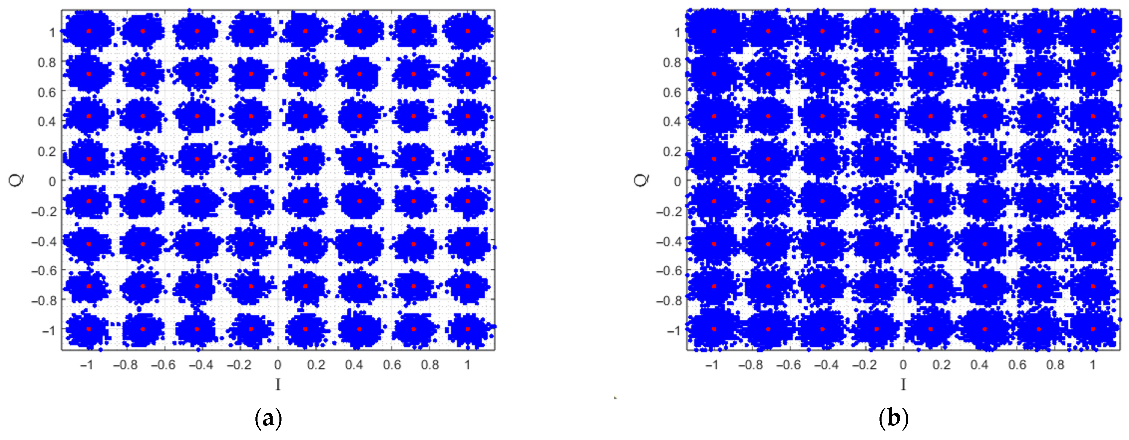
Table 4 reports BER values also registered with the other implementations. Again, accuracy exhibits negligible improvements for small values of SNR, whereas larger differences are registered for SNR approaching 25 dB. Among different circuits, AFFT-cmplx4 [29] and SSM14,12 [19] are the only ones able to achieve precision equal to the standard case. Designs with C4/2 Ahma [23] and C4/2 Momeni [22] also offer remarkable results, achieving BER similar to A-FFT153,2,3, while SRoBA and ASRoBA [27] perform in the middle, offering BER of 7.4 × 10⁻⁴. On the other hand, LoBA [28] has the worst performance, with BER around 10−1. Figure 8 represents the QAM constellation obtained after the reception of the image for A-FFT153,2,3 and ASRoBA [27] in the case SNR = 25 dB. The constellation points are clearly distinguishable in the case of A-FFT15,2,3 (see Figure 8a), whereas the plot for ASRoBA [27] shows a higher level of noise (see Figure 8b). This behavior is further confirmed in Figure 9, depicting the Cameraman images after the reception. Indeed, the image rebuilt with ASRoBA [27] exhibits visible differences with respect to the original case (see the white dots spread in the background). Conversely, results obtained with A-FFT153,2,3 are practically unchanged with respect to the original image, as also indicated by the higher value of BER.

5. Discussion

As shown in the previous sections, the proposed FFT processor is able to offer a wide range of precision depending on the choice of the approximation parameters t and m. Indeed, as also shown in Figure 5 and Table 2, increasing the number of truncated terms in the PPM of multipliers leads to a worsening of accuracy. Additionally, the additive logic used to handle the skipping technique and cross-power domain appears to be compensated by the fixed-width approach, used to approximate multipliers. Accordingly, a consistent reduction in power is registered, with implementation A-FFT158,8,10 that approaches the best energy improvement (−33%), while area improvement is limited to 7%. Critical path delay also exhibits acceptable results, featuring only a slight worsening of performance with respect to the standard FFT.
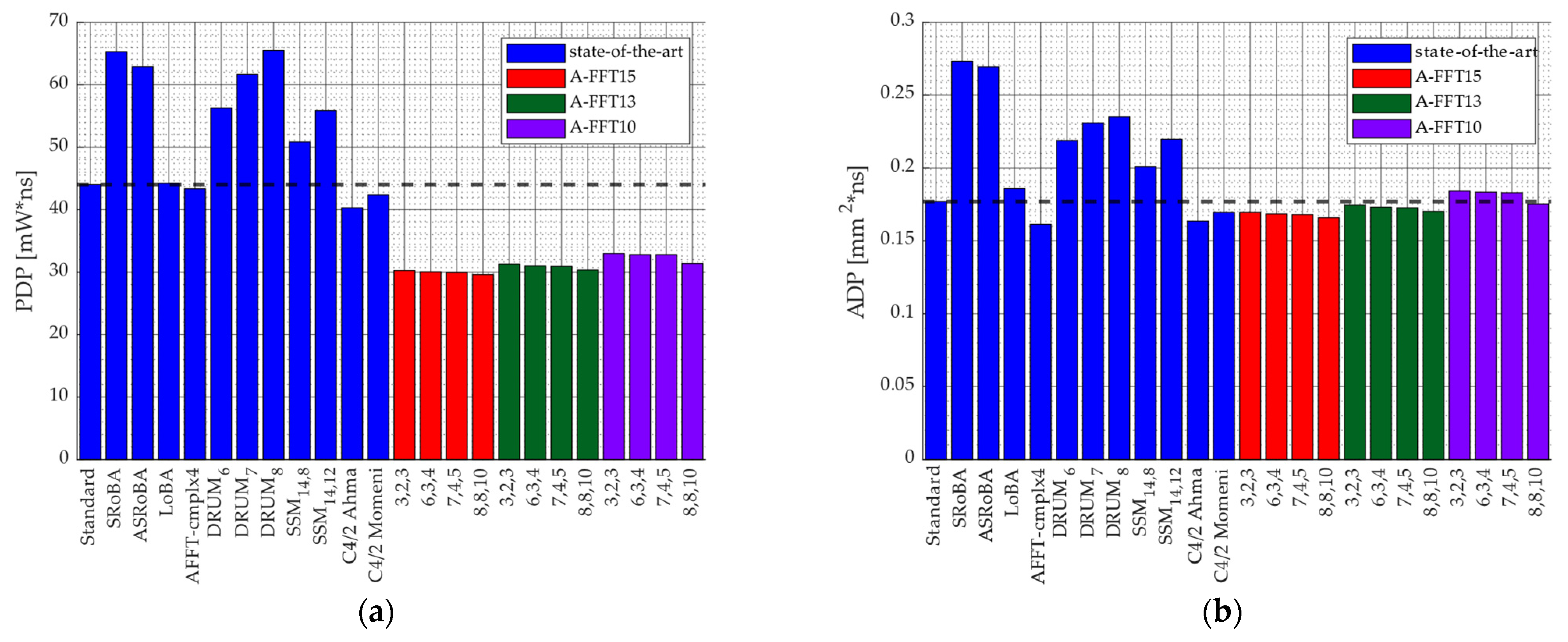
Similarly, implementations obtained with C4/2 Ahma [23], C4/2 Momeni [22] and approximate Booth multipliers [29] are able to achieve high accuracy. Here, only the least significant part of the multiplier PPM is approximated, whereas no error is introduced in the most significant part. On the other hand, the high precision is achieved at the cost of hardware performance, as demonstrated by the limited power saving (up to 7.4%). In the case of segmented multipliers like DRUM and SSM, the FFT accuracy strongly depends on segment bit-width, having an SNR gap of 15 dB passing from SSM14,8 to SSM14,12. Although power and area reduction are consistent, the critical path delay is almost limited due to the logic used for the input segment selection and for the bit-width extension of the result. Similar reasoning is also valid for SRoBA, ASRoBA, and LoBA, as the recoding technique requires additional shifters at the input and the output of the multipliers. To put results in perspective, Figure 10 depicts the power-delay-product (PDP) and the area-delay-product (ADP) registered for the investigated FFT processors; the blue bars represent state-of-the-art architecture, while red, green, and purple bars correspond to the proposed A-FFT15, A-FFT13, and A-FFT10 architectures, respectively, each configured with different m values, shown on the x-axis. The black dashed line highlights the PDP and ADP levels of the standard implementation. As shown, only the proposed FFTs achieve remarkable improvements in PDP (in the order of 30%). PDP reduction is negligible in the case of C4/2 Ahma [23], C4/2 Momeni [22], and AFFT-cmplx4 [29], whereas a clear worsening is registered with the other implementations, mainly due to the larger critical path delay. The proposed A-FFT15 is also the only one able to offer ADP improvement along with C4/2 Ahma [23], C4/2 Momeni [22], and AFFT-cmplx4 [29], registering reductions up to 5%.
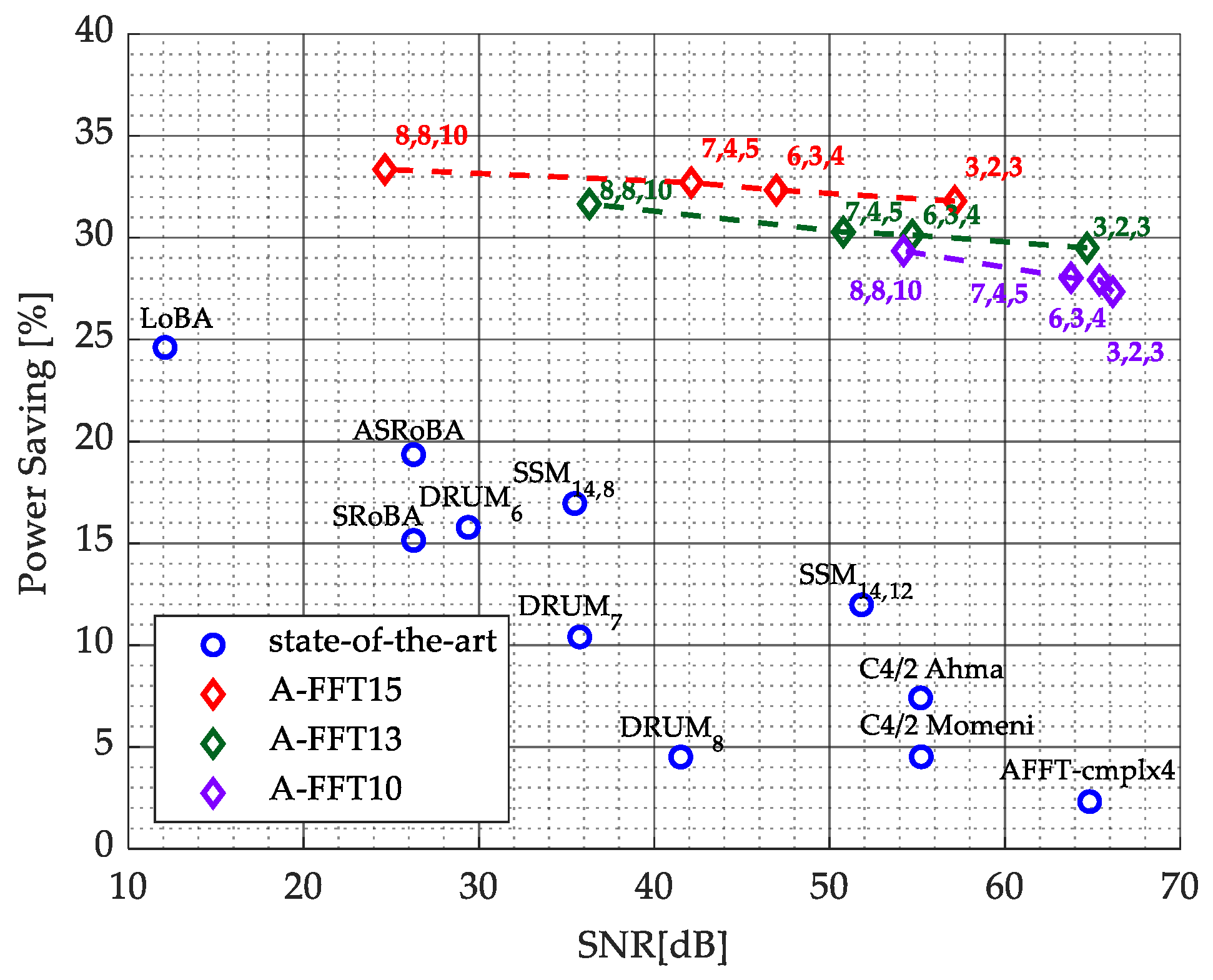
Finally, Figure 11 compares accuracy and power behavior with the aim of offering a joint assessment between hardware performance and precision of calculations. Implementations close to the top-right corner of the figure exhibit the higher SNR with the higher power reduction. Performance of A-FFT10, A-FFT13, and A-FFT15 implementations is highlighted by the dotted lines. As shown, the proposed designs offer the best power-accuracy trade-off in all cases, allowing the possibility to achieve the largest power saving in a wide range of accuracy.

6. Conclusions

In this paper, we propose a novel low-power, hardware-efficient design for the SDF radix-22 FFT processor exploiting approximate multiplication and voltage scaling. To save power consumption, multiplications are skipped when twiddle factors exhibit trivial values, and a suitable gating on the signals is also applied to reduce the switching activity of the circuit. Additionally, the ROM content is suitably modified to minimize the propagation of glitches when the circuit crosses the skipping condition. At the same time, a novel fixed-width technique is proposed to further alleviate hardware burden by (i) discarding the columns of the least significant part of the PPM and (ii) pruning a selected number of partial product terms in the most significant part. In the latter case, the probability of each partial product being high is exploited to identify and remove terms that are often zero, as they weakly affect the FFT computation. The number of negligible partial products is then determined so as to equally distribute the approximation error among all PPM rows, achieving an optimal balance between hardware simplification and accuracy of results. Finally, memory buffers, required to store samples processed by butterflies, are realized in a separate power domain with a lower supply voltage for further improvements.
Accuracy analyses revealed that the proposed approximate FFT is able to span a wide range of values of SNR and MSE depending on the choice of truncation parameters, being competitive with the investigated implementations. The adoption of skip-and-approximate multiplications, suitably customized on features of twiddle factors, and the design of optimized memory buffers led to power reductions superior to other implementations (up to 33%), which basically exploit general-purpose approximate multipliers taken from literature. Optimal results are also achieved in terms of PDP and ADP, exhibiting the best PDP improvements and competitive ADP behavior. The proposed design was validated through a system-level study within an OFDM receiver, showing that power improvements are achieved without degrading communication performance, as evidenced by the near-optimal BER across different channel SNRs.
Future research will be directed toward improving the area performance of the circuit while preserving high power reductions and accuracy capabilities.

Author Contributions

Conceptualization, G.D.M. and C.P.; methodology, G.D.M. and C.P.; software, C.P.; validation, G.D.M., C.P. and D.D.C.; formal analysis G.D.M.; investigation, G.D.M. and C.P.; resources, G.D.M. and C.P.; data curation, G.D.M. and C.P.; writing—original draft preparation, G.D.M.; writing—review and editing, D.D.C. and A.G.M.S.; visualization, D.D.C. and A.G.M.S.; supervision, D.D.C. and A.G.M.S.; project administration, D.D.C. and A.G.M.S. All authors have read and agreed to the published version of the manuscript.

Funding

This research received no external funding.

Data Availability Statement

Matlab R2023b Image Processing Toolbox dataset.

Conflicts of Interest

The authors declare no conflicts of interest.

Abbreviations

The following abbreviations are used in this manuscript:
DFTDiscrete Fourier Transform
FFTFast Fourier Transform
SNRSignal-to-Noise Ratio
MSEMean Squared Error
BERBit Error Rate
PDPPower-Delay-Product
ADPArea-Delay-Product
SDFSingle-path Delay Feedback
SRAMStatic Random Access Memory

Appendix A

To solve (18), let us rewrite the generic summation as follows:
i = s 1 s 2 2 i = i = 0 s 2 2 i i = 0 s 1 1 2 i
Having that
i = 0 s 1 α i = 1 α s 1 α
Equation (A1) becomes:
i = s 1 s 2 2 i = 1 2 s 2 + 1 1 2 1 2 s 1 1 2 = 2 s 2 + 1 2 s 1
Then, substituting proper indices in (A3), the results shown in (18) are found.

References

  1. Shokry, B.; Dessouky, M.; Safar, M.; El-Kharashi, M.W. A dynamically configurable-radix pipelined FFT algorithm for real time applications. In Proceedings of the 2017 12th International Conference on Computer Engineering and Systems (ICCES), Cairo, Egypt, 19–20 December 2017; pp. 402–407. [Google Scholar] [CrossRef]
  2. Qureshi, F.; Takala, J. New Identical Radix-2^k Fast Fourier Transform Algorithms. In Proceedings of the 2016 IEEE International Workshop on Signal Processing Systems (SiPS), Dallas, TX, USA, 26–28 October 2016; pp. 195–200. [Google Scholar] [CrossRef]
  3. Lee, Y.-C.; Chi, T.-S.; Yang, C.-H. A 2.17-mW Acoustic DSP Processor with CNN-FFT Accelerators for Intelligent Hearing Assistive Devices. IEEE J. Solid-State Circuits 2020, 55, 2247–2258. [Google Scholar] [CrossRef]
  4. Shan, W.; Yang, M.; Wang, T.; Lu, Y.; Cai, H.; Zhu, L.; Xu, J.; Wu, C.; Shi, L.; Yang, J. A 510-nW Wake-Up Keyword-Spotting Chip Using Serial-FFT-Based MFCC and Binarized Depthwise Separable CNN in 28-nm CMOS. IEEE J. Solid-State Circuits 2021, 56, 151–164. [Google Scholar] [CrossRef]
  5. Yue, J.; Liu, Y.; Liu, R.; Sun, W.; Yuan, Z.; Tu, Y.-N.; Chen, Y.-J.; Ren, A.; Wang, Y.; Chang, M.-F.; et al. STICKER-T: An Energy-Efficient Neural Network Processor Using Block-Circulant Algorithm and Unified Frequency-Domain Acceleration. IEEE J. Solid-State Circuits 2021, 56, 1936–1948. [Google Scholar] [CrossRef]
  6. Yu, C.; Yen, M.-H. Area-Efficient 128- to 2048/1536-Point Pipeline FFT Processor for LTE and Mobile WiMAX Systems. IEEE Trans. Very Large Scale Integr. (VLSI) Syst. 2015, 23, 1793–1800. [Google Scholar] [CrossRef]
  7. Cooley, J.; Tukey, J.W. An algorithm for the machine calculation of complex Fourier series. Math. Comput. 1965, 19, 297–301. [Google Scholar] [CrossRef]
  8. Oppenheim, A.; Schafer, R. Discrete-Time Signal Processing; Prentice-Hall: Engelwood Cliffs, NJ, USA, 1989. [Google Scholar]
  9. Garrido, M. A Survey on Pipelined FFT Hardware Architectures. J. Signal Process. Syst. 2022, 94, 1345–1364. [Google Scholar] [CrossRef]
  10. He, S.; Torkelson, M. Design and implementation of a 1024-point pipeline FFT processor. In Proceedings of the IEEE 1998 Custom Integrated Circuits Conference (Cat. No.98CH36143), Santa Clara, CA, USA, 14 May 1998; pp. 131–134. [Google Scholar] [CrossRef]
  11. He, S.; Torkelson, M. A new approach to pipeline FFT processor. In Proceedings of the International Conference on Parallel Processing, Honolulu, HI, USA, 15–19 April 1996; pp. 766–770. [Google Scholar] [CrossRef]
  12. Santhosh, L.; Thomas, A. Implementation of radix 2 and radix 22 FFT algorithms on Spartan6 FPGA. In Proceedings of the 2013 Fourth International Conference on Computing, Communications and Networking Technologies (ICCCNT), Tiruchengode, India, 4–6 July 2013; pp. 1–4. [Google Scholar] [CrossRef]
  13. Esposito, D.; Di Meo, G.; De Caro, D.; Strollo, A.G.M.; Napoli, E. Quality-Scalable Approximate LMS Filter. In Proceedings of the 2018 25th IEEE International Conference on Electronics, Circuits and Systems (ICECS), Bordeaux, France, 9–12 December 2018; pp. 849–852. [Google Scholar] [CrossRef]
  14. Di Meo, G.; De Caro, D.; Saggese, G.; Napoli, E.; Petra, N.; Strollo, A.G.M. A Novel Module-Sign Low-Power Implementation for the DLMS Adaptive Filter with Low Steady-State Error. IEEE Trans. Circuits Syst. I Regul. Pap. 2022, 69, 297–308. [Google Scholar] [CrossRef]
  15. Ansari, M.S.; Cockburn, B.F.; Han, J. An Improved Logarithmic Multiplier for Energy-Efficient Neural Computing. IEEE Trans. Comput. 2021, 70, 614–625. [Google Scholar] [CrossRef]
  16. Han, J.; Orshansky, M. Approximate computing: An emerging paradigm for energy-efficient design. In Proceedings of the 2013 18th IEEE European Test Symposium (ETS), Avignon, France, 27–30 May 2013; pp. 1–6. [Google Scholar] [CrossRef]
  17. Chippa, V.K.; Chakradhar, S.T.; Roy, K.; Raghunathan, A. Analysis and characterization of inherent application resilience for approximate computing. In Proceedings of the 2013 50th ACM/EDAC/IEEE Design Automation Conference (DAC), Austin, TX, USA, 29 May–7 June 2013; pp. 1–9. [Google Scholar] [CrossRef]
  18. Hashemi, S.; Bahar, R.I.; Reda, S. DRUM: A Dynamic Range Unbiased Multiplier for approximate applications. In Proceedings of the 2015 IEEE/ACM International Conference on Computer-Aided Design (ICCAD), Austin, TX, USA, 2–6 November 2015; pp. 418–425. [Google Scholar] [CrossRef]
  19. Narayanamoorthy, S.; Moghaddam, H.A.; Liu, Z.; Park, T.; Kim, N.S. Energy-Efficient Approximate Multiplication for Digital Signal Processing and Classification Applications. IEEE Trans. Very Large Scale Integr. (VLSI) Syst. 2015, 23, 1180–1184. [Google Scholar] [CrossRef]
  20. Di Meo, G.; Saggese, G.; Strollo, A.G.M.; De Caro, D. Design of Generalized Enhanced Static Segment Multiplier with Minimum Mean Square Error for Uniform and Nonuniform Input Distributions. Electronics 2023, 12, 446. [Google Scholar] [CrossRef]
  21. Di Meo, G.; Saggese, G.; Strollo, A.G.M.; De Caro, D. Approximate MAC Unit Using Static Segmentation. IEEE Trans. Emerg. Top. Comput. 2024, 12, 968–979. [Google Scholar] [CrossRef]
  22. Momeni, A.; Han, J.; Montuschi, P.; Lombardi, F. Design and Analysis of Approximate Compressors for Multiplication. IEEE Trans. Comput. 2015, 64, 984–994. [Google Scholar] [CrossRef]
  23. Ahmadinejad, M.; Moaiyeri, M.H.; Sabetzadeh, F. Energy and area efficient imprecise compressors for approximate multiplication at nanoscale. AEU-Int. J. Electron. Commun. 2019, 110, 152859. [Google Scholar] [CrossRef]
  24. Yang, Z.; Han, J.; Lombardi, F. Approximate compressors for error-resilient multiplier design. In Proceedings of the 2015 IEEE International Symposium on Defect and Fault Tolerance in VLSI and Nanotechnology Systems (DFTS), Amherst, MA, USA, 12–14 October 2015; pp. 183–186. [Google Scholar] [CrossRef]
  25. Ha, M.; Lee, S. Multipliers with Approximate 4–2 Compressors and Error Recovery Modules. IEEE Embed. Syst. Lett. 2018, 10, 6–9. [Google Scholar] [CrossRef]
  26. Petra, N.; De Caro, D.; Garofalo, V.; Napoli, E.; Strollo, A.G.M. Design of Fixed-Width Multipliers with Linear Compensation Function. IEEE Trans. Circuits Syst. I Regul. Pap. 2011, 58, 947–960. [Google Scholar] [CrossRef]
  27. Zendegani, R.; Kamal, M.; Bahadori, M.; Afzali-Kusha, A.; Pedram, M. RoBA Multiplier: A Rounding-Based Approximate Multiplier for High-Speed yet Energy-Efficient Digital Signal Processing. IEEE Trans. Very Large Scale Integr. (VLSI) Syst. 2017, 25, 393–401. [Google Scholar] [CrossRef]
  28. Garg, B.; Patel, S.K.; Dutt, S. LoBA: A Leading One Bit Based Imprecise Multiplier for Efficient Image Processing. J. Electron. Test. 2020, 36, 429–437. [Google Scholar] [CrossRef]
  29. Du, J.; Chen, K.; Yin, P.; Yan, C.; Liu, W. Design of An Approximate FFT Processor Based on Approximate Complex Multipliers. In Proceedings of the 2021 IEEE Computer Society Annual Symposium on VLSI (ISVLSI), Tampa, FL, USA, 7–9 July 2021; pp. 308–313. [Google Scholar] [CrossRef]
  30. Ferreira, G.; Pereira, P.T.L.; Paim, G.; Costa, E.; Bampi, S. A Power-Efficient FFT Hardware Architecture Exploiting Approximate Adders. In Proceedings of the 2021 IEEE 12th Latin America Symposium on Circuits and System (LASCAS), Arequipa, Peru, 21–24 February 2021; pp. 1–4. [Google Scholar] [CrossRef]
  31. Zhu, N.; Goh, W.L.; Zhang, W.; Yeo, K.S.; Kong, Z.H. Design of Low-Power High-Speed Truncation-Error-Tolerant Adder and Its Application in Digital Signal Processing. IEEE Trans. Very Large Scale Integr. (VLSI) Syst. 2010, 18, 1225–1229. [Google Scholar] [CrossRef]
  32. Mahdiani, H.R.; Ahmadi, A.; Fakhraie, S.M.; Lucas, C. Bio-Inspired Imprecise Computational Blocks for Efficient VLSI Implementation of Soft-Computing Applications. IEEE Trans. Circuits Syst. I Regul. Pap. 2010, 57, 850–862. [Google Scholar] [CrossRef]
  33. Pereira, P.T.L.; da Costa, P.U.L.; Ferreira, G.d.C.; de Abreu, B.A.; Paim, G.; da Costa, E.A.C.; Bampi, S. Energy-Quality Scalable Design Space Exploration of Approximate FFT Hardware Architectures. IEEE Trans. Circuits Syst. I Regul. Pap. 2022, 69, 4524–4534. [Google Scholar] [CrossRef]
  34. Liu, W.; Liao, Q.; Qiao, F.; Xia, W.; Wang, C.; Lombardi, F. Approximate Designs for Fast Fourier Transform (FFT) with Application to Speech Recognition. IEEE Trans. Circuits Syst. I Regul. Pap. 2019, 66, 4727–4739. [Google Scholar] [CrossRef]
  35. Meinerzhagen, P.; Roth, C.; Burg, A. Towards generic low-power area-efficient standard cell based memory architectures. In Proceedings of the 2010 53rd IEEE International Midwest Symposium on Circuits and Systems, Seattle, WA, USA, 1–4 August 2010; pp. 129–132. [Google Scholar] [CrossRef]
  36. Marinberg, H.; Garzón, E.; Noy, T.; Lanuzza, M.; Teman, A. Efficient Implementation of Many-Ported Memories by Using Standard-Cell Memory Approach. IEEE Access 2023, 11, 94885–94897. [Google Scholar] [CrossRef]
  37. Saggese, G.; Strollo, A.G.M. A Low Power 1024-Channels Spike Detector Using Latch-Based RAM for Real-Time Brain Silicon Interfaces. Electronics 2021, 10, 3068. [Google Scholar] [CrossRef]
  38. Zhou, J.; Singh, K.; Huisken, J. Standard Cell based Memory Compiler for Near/Sub-threshold Operation. In Proceedings of the 2020 27th IEEE International Conference on Electronics, Circuits and Systems (ICECS), Glasgow, UK, 23–25 November 2020; pp. 1–4. [Google Scholar] [CrossRef]
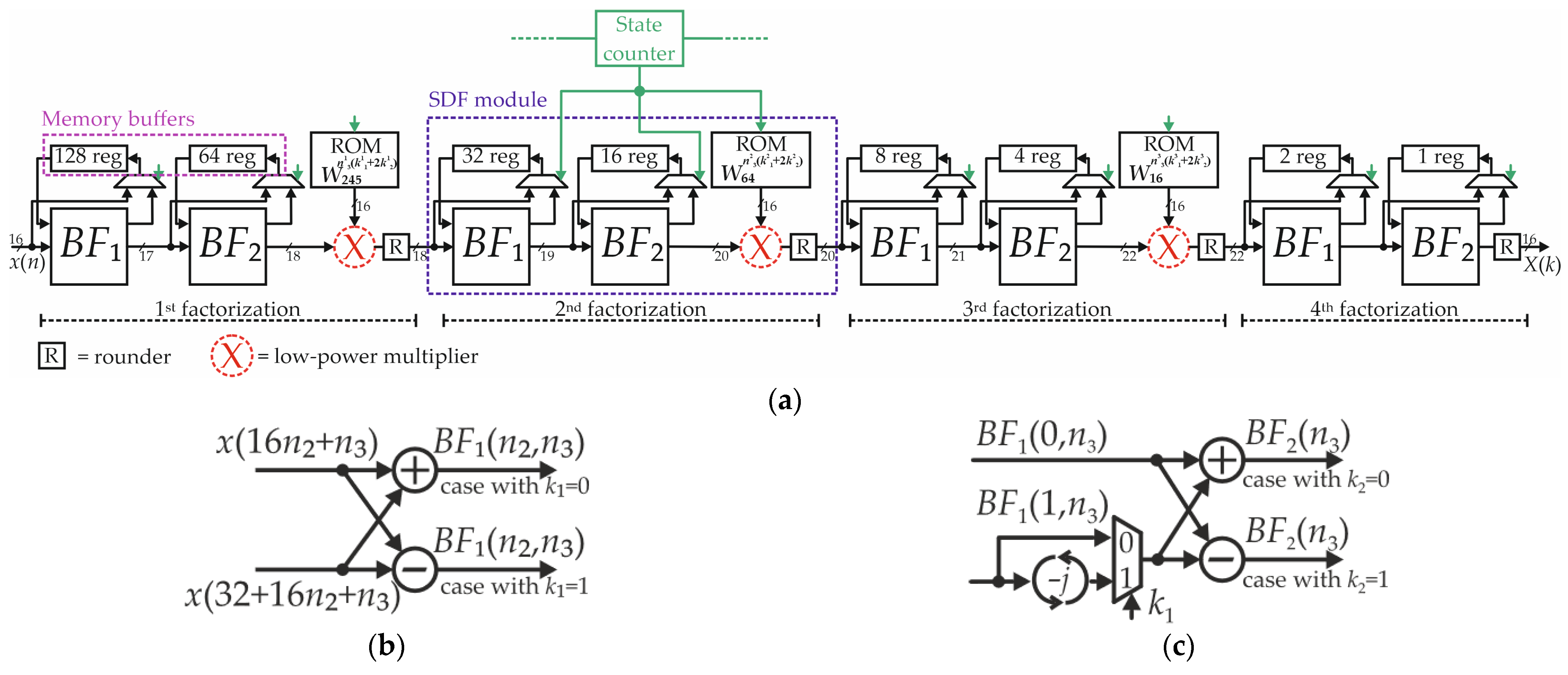
Figure 1. (a) SDF implementation of a 256-point radix-22 FFT. Multipliers depicted in red process complex numbers, thus requiring four real multipliers. Representations of butterflies (b) BF1 and (c) BF2.
Electronics 14 04217 g001
Figure 2. Modified ROM and skipping circuit for multiplications with trivial values of the twiddle factors. Terms BF2,Re and BF2,Im are the real and imaginary parts of the signal computed by the butterfly BF2, while cosm and senm are the modified cosine and sine coefficients. The blue and red arrows depicted near the ROM show when the FFT enters and exits from the skipping condition.
Electronics 14 04217 g002
Figure 3. Partial product matrix of the proposed fixed-width multiplier with truncation in the least and most significant parts of the PPM.
Electronics 14 04217 g003
Figure 4. Probability of having high bits in real and imaginary parts of twiddle factors (a) W 256 n 3 1 ( k 1 1 + 2 k 2 1 ) , (b) W 64 n 3 2 ( k 1 2 + 2 k 2 2 ) , and (c) W 16 n 3 3 ( k 1 3 + 2 k 2 3 ) . The dashed black line represents the threshold probability to neglect partial products in the PPM of multipliers.
Electronics 14 04217 g004
Figure 5. Signal-to-Noise Ratio of the proposed FFT in case of approximation in the multiplier (a) of the first module only, (b) of the first and the second modules, and (c) of all modules.
Electronics 14 04217 g005
Figure 6. Simplified block diagram of the OFDM communication. The bit highlighted in red after the reception is wrong due to the effects of channel noise.
Electronics 14 04217 g006
Figure 7. Bit Error Rate registered for channel SNR in the range 0 dB−25 dB using proposed FFT processors with (a) t = 10, (b) t = 13, and (c) t = 15 and four different configurations of m parameters.
Electronics 14 04217 g007
Figure 8. QAM constellation after the transformation and demodulation with SNR = 25 dB, computed with FFTs (a) A-FFT153,2,3 and (b) ASRoBa.
Electronics 14 04217 g008
Figure 9. (a) Original “Cameraman” image and results after the processing with (b) A-FFT153,2,3 and (c) ASRoBA.
Electronics 14 04217 g009
Figure 10. (a) Power-delay-product and (b) area-delay-product for the investigated FFT processors. The black dashed line highlights the PDP and ADP levels of the standard implementation.
Electronics 14 04217 g010
Figure 11. SNR vs. power saving behavior of the discussed implementations. The blue circles show results of state-of-the-art designs, while red, green, and purple diamonds show the behavior of the proposed architecture with t = 15, t = 13, and t = 10, respectively, and several values of m parameters.
Electronics 14 04217 g011
Table 1. Values of twiddle factor W 16 n 3 3 ( k 1 3 + 2 k 2 3 ) as a function of the ROM address in the 16-point DFT of the third iteration.
ROM Address n 3 3 k 1 3 + 2 k 2 3 cos ( 2 π n 3 3 ( k 1 3 + 2 k 2 3 ) 16 ) sin ( 2 π n 3 3 ( k 1 3 + 2 k 2 3 ) 16 ) sk
000100
101100
202100
303100
420100
5217.07 × 10−1−7.07 × 10⁻¹¹
6226.12 × 10−17−9.99 × 10⁻¹¹
723−7.07 × 10⁻¹−7.07 × 10⁻¹¹
8101.00 × 10−00.00 × 10−01
9119.24 × 10−1−3.83 × 10⁻¹¹
10127.07 × 10−1−7.07 × 10⁻¹¹
11133.83 × 10−1−9.24 × 10⁻¹¹
12301.00 × 10−00.00 × 10−01
13313.83 × 10−1−9.24 × 10⁻¹¹
1432−7.07 × 10⁻¹−7.07 × 10⁻¹¹
1533−9.24 × 10−13.83 × 10−11
Table 2. Number of pruned partial products mh as a function of the worst-case row index h* and the generic row index h.
Values of mhh* < 2 and th* < t + 12 ≤ h* < th* > t + 1
h < 2 and th < t + 1 log 2 P max P ( w h ) · 2 m 1 + 1 log 2 2 · P max P ( w h ) · 2 m 1 + 1 log 2 2 h * t · P max P ( w h ) · 2 m 1 + 1
2 ≤ h < t log 2 1 2 · P max P ( w h ) · 2 m 1 + 1 log 2 P max P ( w h ) · 2 m 1 + 1 log 2 2 h * t 1 · P max P ( w h ) · 2 m 1 + 1
h > t + 1 log 2 2 t h * · P max P ( w h ) · 2 m 1 + 1 log 2 2 t + 1 h * · P max P ( w h ) · 2 m 1 + 1 log 2 P max P ( w h ) · 2 m 1 + 1
Table 3. Accuracy and hardware comparison between the proposed FFT processors and the state-of-the-art designs.
FFT ImplementationSNR [dB]MSEDelay [ns]Area [mm2]Area Saving [%]Power [mW]Power Saving [%]
Standard66.24.13 × 10−55.160.0343-8.53-
SRoBA [27,33]26.34.03 × 10−19.020.0303−11.67.24−15.1
ASRoBA [27,33]26.34.04 × 10−19.140.0295−14.16.88−19.4
LOBA0_4 [28,33]12.11.05 × 10+16.880.0270−21.36.43−24.6
AFFT-cmplx4 [29]64.85.61 × 10−55.200.0310−9.68.33−2.3
DRUM6 [18,33]29.41.97 × 10−17.830.0279−18.67.18−15.8
DRUM7 [18,33]35.84.56 × 10−28.070.0286−16.57.64−10.4
DRUM8 [18,33]41.51.21 × 10−28.040.0292−14.78.15−4.5
SSM14,8 [19]35.54.85 × 10−27.180.0280−18.47.08−17.0
SSM14,12 [19]51.81.12 × 10−37.440.0295−13.97.51−12.0
Comp4/2 Ahma [23]55.25.16 × 10−45.100.0321−6.57.90−7.4
Comp4/2 Momeni [22]55.25.11 × 10−45.200.0326−4.98.14−4.5
A-FFT153,2,357.13.29 × 10−45.210.0326−5.05.82−31.8
A-FFT156,3,447.03.43 × 10−35.200.0324−5.65.77−32.3
A-FFT157,4,542.11.05 × 10−25.210.0323−5.95.74−32.7
A-FFT158,8,1024.65.87 × 10−14.790.0319−7.15.68−33.4
A-FFT133,2,364.75.81 × 10−55.200.0336−2.26.01−29.5
A-FFT136,3,454.75.75 × 10−45.200.0333−2.95.96−30.1
A-FFT137,4,550.81.42 × 10−35.200.0332−3.25.95−30.3
A-FFT138,8,1036.34.00 × 10−25.200.0327−4.65.83−31.7
A-FFT103,2,366.24.13 × 10−55.320.0346+1.06.20−27.3
A-FFT106,3,465.44.94 × 10−55.330.0344+0.46.15−27.9
A-FFT107,4,563.87.16 × 10−55.340.0343+0.06.14−28.0
A-FFT108,8,1054.26.46 × 10−45.200.0337−1.86.03−29.4
Table 4. Bit Error Rate performance obtained with FFT computed implementing approximate multipliers.
FFT ImplementationChannel SNR
6 dB12 dB18 dB20 dB22 dB24 dB25 dB
Standard2.22 × 10−11.03 × 10−12.01 × 10−26.75 × 10−31.22 × 10−31.01 × 10−41.71 × 10−5
SRoBA [27,33]2.23 × 10−11.06 × 10−12.55 × 10−21.12 × 10−23.93 × 10−31.30 × 10−37.40 × 10⁻⁴
ASRoBA [27,33]2.23 × 10−11.06 × 10−12.55 × 10−21.12 × 10−23.92 × 10−31.31 × 10−37.46 × 10⁻⁴
LOBA [28,33]2.55 × 10−11.94 × 10−11.81 × 10−11.80 × 10−11.81 × 10−11.80 × 10−11.80 × 10⁻¹
AFFT-cmplx4 [29]2.22 × 10−11.03 × 10−12.02 × 10−26.72 × 10−31.24 × 10−31.01 × 10−41.71 × 10⁻⁵
DRUM6 [18,33]2.24 × 10−11.07 × 10−12.43 × 10−29.82 × 10−32.73 × 10−35.56 × 10−42.23 × 10⁻⁴
DRUM7 [18,33]2.23 × 10−11.05 × 10−12.14 × 10−27.50 × 10−31.58 × 10−31.73 × 10−43.81 × 10⁻⁵
DRUM8 [18,33]2.23 × 10−11.04 × 10−12.06 × 10−26.90 × 10−31.29 × 10−31.22 × 10−42.09 × 10⁻⁵
SSM14,8 [19]2.23 × 10−11.05 × 10−12.15 × 10−27.54 × 10−31.56 × 10−31.73 × 10−43.43 × 10⁻⁵
SSM14,12 [19]2.22 × 10−11.03 × 10−12.02 × 10−26.87 × 10−31.27 × 10−31.10 × 10−41.71 × 10⁻⁵
C4/2 Ahma [23]2.22 × 10−11.03 × 10−12.07 × 10−27.17 × 10−31.43 × 10−31.83 × 10−44.76 × 10⁻⁵
C4/2 Momeni [22]2.22 × 10−11.03 × 10−12.07 × 10−27.17 × 10−31.44 × 10−31.85 × 10−44.76 × 10⁻⁵
A-FFT153,2,32.23 × 10−11.04 × 10−12.11 × 10−27.31 × 10−31.51 × 10−32.09 × 10−44.76 × 10−5
A-FFT156,3,42.24 × 10−11.08 × 10−12.92 × 10−21.48 × 10−26.70 × 10−33.26 × 10−32.18 × 10−3
A-FFT157,4,52.28 × 10−11.17 × 10−14.74 × 10−23.41 × 10−22.55 × 10−22.03 × 10−21.86 × 10−2
A-FFT158,8,103.28 × 10−13.02 × 10−12.92 × 10−12.91 × 10−12.90 × 10−12.90 × 10−12.89 × 10−1
A-FFT133,2,32.22 × 10−11.03 × 10−12.03 × 10−26.80 × 10−31.23 × 10−31.14 × 10−41.71 × 10−5
A-FFT136,3,42.23 × 10−11.04 × 10−12.14 × 10−27.76 × 10−31.73 × 10−32.78 × 10−46.66 × 10−5
A-FFT137,4,52.23 × 10−11.05 × 10−12.38 × 10−29.61 × 10−32.89 × 10−37.37 × 10−43.20 × 10−4
A-FFT138,8,102.42 × 10−11.52 × 10−11.07 × 10−19.90 × 10−29.44 × 10−29.12 × 10−29.01 × 10−2
A-FFT103,2,32.22 × 10−11.03 × 10−12.01 × 10−26.76 × 10−31.22 × 10−39.71 × 10−51.71 × 10−5
A-FFT106,3,42.22 × 10−11.03 × 10−12.02 × 10−26.79 × 10−31.23 × 10−31.08 × 10−42.09 × 10−5
A-FFT107,4,52.23 × 10−11.03 × 10−12.02 × 10−26.82 × 10−31.25 × 10−31.14 × 10−42.28 × 10−5
A-FFT108,8,102.23 × 10−11.04 × 10−12.27 × 10−28.57 × 10−32.15 × 10−33.77 × 10−41.29 × 10−4
Disclaimer/Publisher’s Note: The statements, opinions and data contained in all publications are solely those of the individual author(s) and contributor(s) and not of MDPI and/or the editor(s). MDPI and/or the editor(s) disclaim responsibility for any injury to people or property resulting from any ideas, methods, instructions or products referred to in the content.