Article

A Three-Terminal Modular-Multilevel-Converter-Based Power Electronic Transformer with Reduced Voltage Stress for Meshed DC Systems

1
Guangdong Provincial Key Laboratory of Intelligent Operation and Control for New Energy Power System, Guangzhou 510663, China
2
Electric Power Research Institute, China Southern Power Grid, Guangzhou 510663, China
3
School of Electronic and Electrical Engineering, Shanghai University of Engineering Science, Shanghai 201620, China
*
Author to whom correspondence should be addressed.
Electronics 2025, 14(21), 4192; https://doi.org/10.3390/electronics14214192 (registering DOI)
Submission received: 25 September 2025 / Revised: 13 October 2025 / Accepted: 21 October 2025 / Published: 27 October 2025

Abstract

The traditional DC distribution grid is evolving into a meshed structure to create additional energy exchange paths and integrate the rapidly growing renewable energy sources. However, existing converter stations lack sufficient power flow controllability, necessitating the development of multiport power electronic transformers to address potential power flow congestion and high loss issues. This paper proposes a compact multi-terminal modular-multilevel-converter-based power electronic transformer (M3C-PET). This device enables flexible power flow regulation of the connected feeders through adopting two small-capacity power flow control modules (PFCMs). The simple structure and reduced switching count make the proposed PET more competitive and prominent and more cost-effective. Furthermore, this paper elaborates on the operational principle of the proposed device and presents a multilayer power balancing control strategy along with a power flow control scheme. These control strategies are designed based on the internal and external energy distribution mechanism of the proposed PET. The feasibility and effectiveness of the proposed topology and control schemes are rigorously validated through both a MATLAB/Simulink simulation model and a scaled-down experimental prototype.

1. Introduction

Modern DC grid systems have attracted growing attention in recent years, owing to their inherent advantages, including eliminating reactive power compensation requirements and enabling efficient integration of renewable energy sources over wide areas [1,2]. To accommodate more energy entities and clusters, the radial and ring DC configurations are evolving into meshed structures associated with multiport power electronic transformers (PETs) [3,4]. Compared to the existing AC and DC layouts, the meshed DC grid can provide enough energy paths for inter-regional grid interconnection and multi-terminal renewable energy consumption [5]. Nevertheless, potential power congestion and overload issues may occur in the meshed DC system when the number of controllable nodes is no greater than that of the connected lines, leading to uncontrolled power flow dispatch [6,7].
So far, multiple types of DC PETs have been proposed to connect DC grids with different configurations and voltage levels [8]. Owing to the modularity, high efficiency, and bidirectional power controllability, the dual active bridge (DAB) formed by the full bridges is more favorable for the DC PET. To adapt to high-voltage and high-power applications, multiple modular DC PET schemes based on the DAB, including the input-series–output-parallel (ISOP), input-series–output-series (ISOS), input-parallel–output-series (IPOS), and input-parallel–output-parallel (IPOP) structures, were proposed [9]. Nevertheless, the large DC capacitors adopted in the DAB modules increase the volume and cost of DC PET. Another DAB-based DC PET replaces single switches with half-bridge or full-bridge submodules to withstand high power and voltage [10,11]. However, the complexity of energy balance control and the difficulty of manufacturing the corresponding transformers hinder the practical application of these devices. Compared to the isolated DC PETs, non-isolated DC PETs were introduced, featuring low switch count, low capacitive energy storage, and low magnetic requirements [12]. Notably, the aforementioned isolated and non-isolated DC PET topologies need to sustain the full power and voltage of the connected DC lines, thereby posing significant challenges to port extension in terms of cost and volume.
On this basis, another type of PET, termed DC power flow controller (DCPFC), has been introduced in the network to alleviate the cost and volume by adopting partial-power modules [13]. Among all the DCPFCs, the resistance type features a simple structure and easy control at the cost of increasing losses. Moreover, this device cannot achieve bidirectional power regulation, limiting its power regulation range [14,15]. Another type of DCPFC introduces a series adjustable voltage source (SAVS) to adjust the corresponding line power flow. Ref. [16] presented a thyristor-based adjustable voltage source to regulate the power flow, requiring an external power supply and high-voltage isolation devices. To address the limitations, the interline DCPFC (IDCPFC) was proposed to achieve independent power flow control without external power supplies and isolation devices, using small-capacity converters [17]. Early single-capacitor IDCPFCs [18] suffered from non-negligible line current ripple, which was mitigated by later separate-capacitor designs [19]. Another variant [20,21,22] enabled easy port expansion with fewer switches for meshed HVDC grids. Though IDCPFCs eliminate external devices, their complex topologies and control schemes interfere with their practical use in meshed DC systems. A hybrid IDCPFC integrating SAVS [23] extended the power flow regulation range but reintroduced external devices, increasing system initial investment.
Unlike the previous topologies, this article proposes a multi-terminal modular-multilevel-converter-based power electronic transformer (M3C-PET) comprising a host MMC and two power flow control modules (PFCMs). Each PFCM employs a three-phase full-bridge structure. Since MMC stations have been widely adopted in high-voltage DC (HVDC) applications [24], the meshed DC grid system can be easily constructed by interconnecting multiple DC grids through the PFCMs. The proposed topology eliminates the need for an external power supply and high-voltage isolation device, enabling independent and bidirectional power flow control between adjacent DC grids.
Section 2 elaborates on the derivation and basic operational principle of the M3C-PET. Section 3 details the system parameters design. In Section 4, a multilayer internal energy balancing control strategy is proposed, accompanied by a comprehensive analysis. Section 5 and Section 6 present the simulation and experiment verification of the proposed M3C-PET topology and its control schemes. Section 7 concludes this article.

2. Topology and Operating Principle of the M3C-PET

Figure 1 shows the topology of the proposed M3C-PET, where two three-phase full-bridge PFCMs (PFCM-A and B) are embedded in a host MMC. The PFCMs are series-connected to the MMC’s upper and lower arms’ top and bottom submodules (SMs). The PFCM’s output ports work as the positive and negative poles of the DC ports for grid interconnection. The power flow can be changed by adjusting the DC voltage difference between the outputs. To maintain normal operation and internal energy balance of the M3C-PET, the energy interaction between the PFCMs and the MMC needs to be well-controlled to ensure real-time power balance.
In this section, Phase-a is taken as an example for the M3C-PET’s power balance mechanism analysis. As shown in Figure 1, the AC grid voltage and current of Phase-a are denoted as ua and ia, respectively; eap and ean stand for the fundamental upper and lower arm voltages of the host MMC; the MMC’s upper and lower arm voltages are uap and uan; the voltages over the upper and lower switches of the PFCM are denoted as uakp and uakn (k = A, B), respectively; Io1 and Io2 represent the currents of the two DC ports; the DC output voltages are denoted as Uo1 and Uo2.
In Phase-a, the grid voltage and current are
u a = U sin ω t i a = I sin ω t φ
where U and I are the amplitudes of the AC-side grid voltage and current; ω is the fundamental frequency of the AC grid; and ϕ is the power factor angle.
eap and ean have the following relationship.
e a p = e a n = E sin ω t δ
Here, E is the fundamental voltage amplitude of eap and ean; δ is the phase difference between the MMC’s fundamental voltage and the grid voltage.
The AC-side active power Pin and reactive power Qin of the host MMC can be derived as
P i n = 3 2 E I cos φ δ Q i n = 3 2 E I sin φ δ .
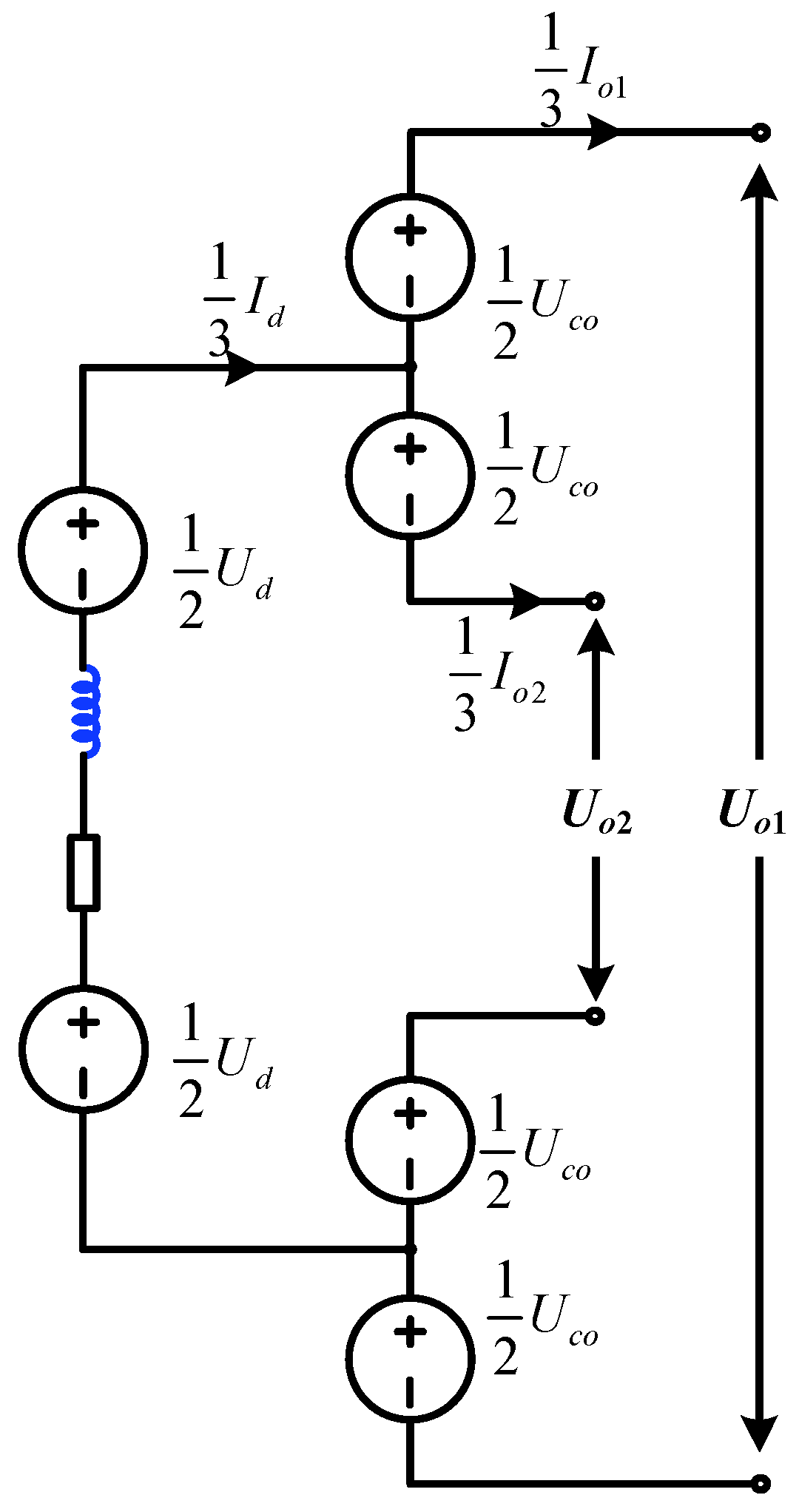
According to the equivalent DC circuit shown in Figure 2, the DC current Id of the host MMC satisfies the following relationship.
I d = I o 1 + I o 2
When the host MMC operates under normal conditions, the upper and lower arm currents share the same amplitude with opposite phase angle. The DC current is evenly divided and dispatched into three phases. Therefore, the Phase-a upper and lower arms currents of the host MMC can be calculated as
i a p t = 1 3 I d 1 2 i a t = 1 3 I d 1 2 I sin ω t φ i a n t = 1 3 I d + 1 2 i a t = 1 3 I d + 1 2 I sin ω t φ .
The output DC currents are coming from the PFCMs. Assuming the DC and fundamental AC current components are equally distributed in the upper and lower arms of each phase, the currents in the upper and lower arms of Phase-a can be expressed as
i a A p t = 1 3 I o 1 1 4 I sin ω t φ i a A n t = 1 3 I o 2 + 1 4 I sin ω t φ i a B p t = 1 3 I o 2 1 4 I sin ω t φ i a B n t = 1 3 I o 1 + 1 4 I sin ω t φ .
The average switching functions of the upper and lower switches in each PFCM are set as
F a A p t = 1 2 1 m P F C sin ω t δ P F C F a A n t = 1 2 1 + m P F C sin ω t δ P F C F a B p t = 1 2 1 m P F C sin ω t δ P F C F a B n t = 1 2 1 + m P F C sin ω t δ P F C ,
where mPFC is the input side voltage modulation index of the PFCM, and δPFC is the phase difference between the average switching function’s fundamental AC component and the AC grid voltage.
The average voltages of the upper and lower switching devices in PFCMs A and B are obtained as
u a k p t = U C 0 2 1 m P F C sin ω t δ P F C u a k n t = U C 0 2 1 + m P F C sin ω t δ P F C     k = A ,   B
Here, UC0 represents the PFCM’s capacitor voltage. The MMC upper and lower arms voltages uap and uan can be calculated by Kirchhoff’s voltage law.
u a p t = U d 2 e a p + U C 0 2 m P F C sin ω t δ P F C u a n t = U d 2 + e a n U C 0 2 m P F C sin ω t δ P F C .
where Ud is the MMC DC-side voltage.
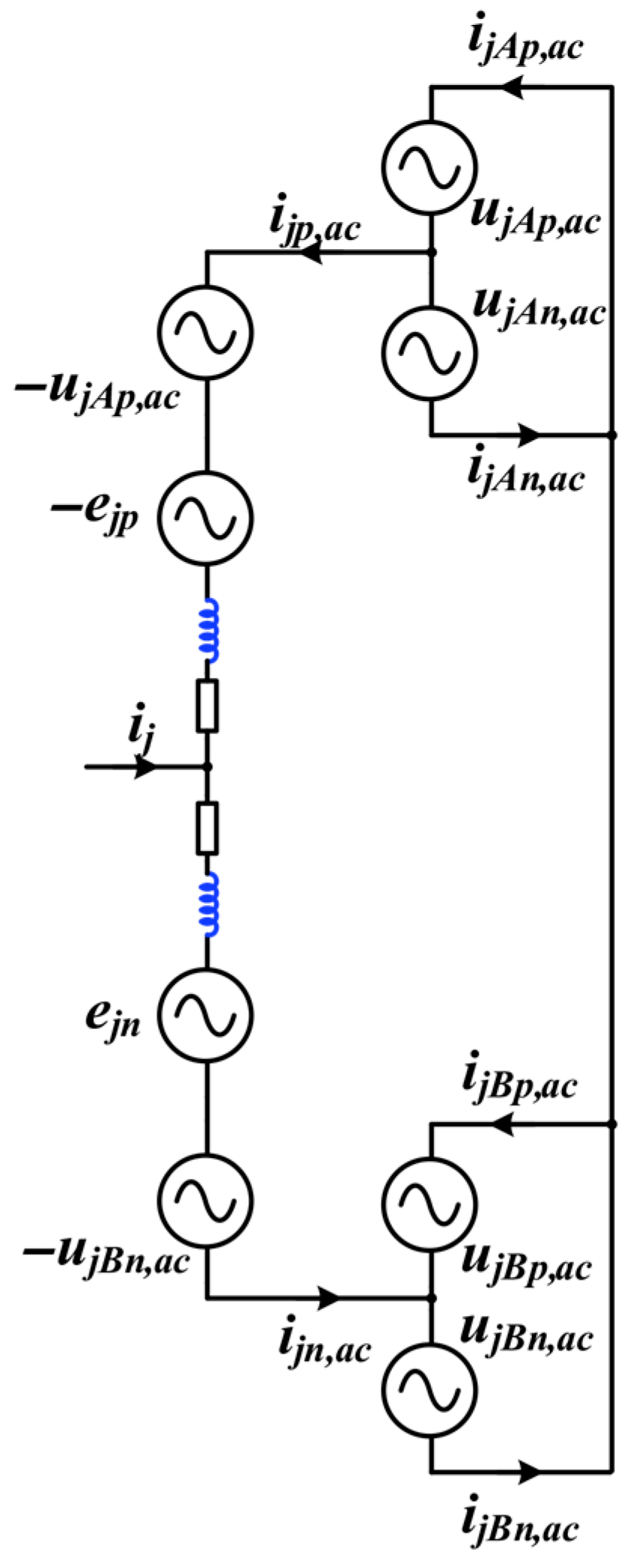
According to (5), (6), (8) and (9), the single-phase DC and AC equivalent circuits of the M3C-PET are illustrated in Figure 2 and Figure 3, respectively.
In Figure 3, ijp,ac and ijn,ac (j = a, b, c) are the upper and lower arm fundamental currents of the host MMC; ujkp,ac and ujkn,ac (j = a, b, c; k = A, B) are the fundamental voltages over the corresponding upper and lower switches of the PFCMs; ijkp,ac and ijkn,ac (j = a, b, c; k = A, B) are the output currents of the PFCMs with fundamental frequency.
According to Figure 2, the DC port voltages of the PFCMs can be expressed as
U o 1 = U d + U C 0 U o 2 = U d U C 0 .
The total power exchange between MMC and DC grid should satisfy the following criterion.
P o u t = U o 1 I o 1 + U o 2 I o 2 = U d I d + U C 0 I o 1 I o 2 .
Based on the equivalent circuits of the M3C-PET, the power variations of the MMC upper and lower arms (Pp and Pn) and the counterparts of PFCMs (PA and PB) can be derived as
P p = P n = U d I d 2 3 4 E I cos φ δ + 3 U C 0 8 m P F C I cos φ δ P F C P A = P B = 1 2 U C 0 I o 1 I o 2 3 U C 0 8 m P F C I cos φ δ P F C
To maintain the power balance between the host MMC and the PFCMs, (12) should satisfy the following criterion.
1 2 U C 0 I o 1 I o 2 3 U C 0 8 m P F C I cos φ δ P F C = 0 U d I d 2 + 3 U C 0 8 m P F C I cos φ δ P F C 3 4 E I cos φ δ = 0
Therefore, the power exchanged P between the AC and DC grids can be obtained.
P = U d I d + U C 0 I o 1 I o 2 = 3 2 E I cos φ δ .
The voltage modulation degree of the PFCM’s input side can be calculated based on (14).
m P F C = 2 E I o 1 I o 2 cos φ δ P cos φ δ P F C .
The DC port voltages of the M3C-PET can be flexibly regulated through (15). Based on this foundation, the power flow of the two DC grids can be effectively controlled by adjusting the DC port voltage difference. Notably, the capacitor voltage of the PFCM remains consistently positive, which ensures that only positive voltage can be applied to the connected DC line. Moreover, the system-level power flow control is designed to solve power congestion and overload issues, without requiring fast dynamic response.

3. Parameter Design of the M3C-PET

The topology of PFCM consists of a three-phase half-bridge module. The input of each PFCM is series-connected to the host MMC arms, while the current stress across the PFCM matches that of the MMC SMs. Hence, the PFCM’s parameter can be designed according to the same criteria as those of the MMC SMs. However, due to the different voltage fluctuation mechanisms between the PFCM and the host MMC, the PFCM’s capacitor C0 should be designed separately. Taking PFCM-A as an example, the average current flowing through the upper and lower switches of the PFCM can be calculated according to (7).
i a A p t = 1 2 1 m P F C sin ω t δ P F C i a p i b A p t = 1 2 1 m P F C sin ω t δ P F C 2 π 3 i b p i c A p t = 1 2 1 m P F C sin ω t δ P F C + 2 π 3 i c p i a A n t = 1 2 1 + m P F C sin ω t δ P F C i a p i b A n t = 1 2 1 + m P F C sin ω t δ P F C 2 π 3 i b p i c A n t = 1 2 1 + m P F C sin ω t δ P F C + 2 π 3 i c p
Therefore, the currents of the PFCM-A can be derived by substituting (5) into (16).
j = a , b , c i j A p = 1 2 I d + 3 8 m P F C I cos ( φ δ P F C ) j = a , b , c i j A n = 1 2 I d 3 8 m P F C I cos ( φ δ P F C ) .
The PFCM’s capacitor current can also be obtained as follows.
i C A = 1 2 ( I o 2 I o 1 ) + 3 8 m P F C cos ( φ δ P F C ) .
The PFCM’s capacitor voltage variation can be deduced by integrating (18).
Δ u C A = 1 C 0 0 t 1 2 ( I o 2 I o 1 ) + 3 8 m P F C cos ( φ δ P F C ) d t
By substituting (15) into (19), ΔuCA equals zero. Unlike the MMC SM capacitor, the PFCM’s capacitor only needs to suppress the higher-order frequency harmonics. Thus, the PFCM’s capacitance is much smaller than that of the MMC SMs. The corresponding capacitor design can refer to the method presented in Ref. [18], which will not be further discussed in this article.

4. Coordinated Control Strategy

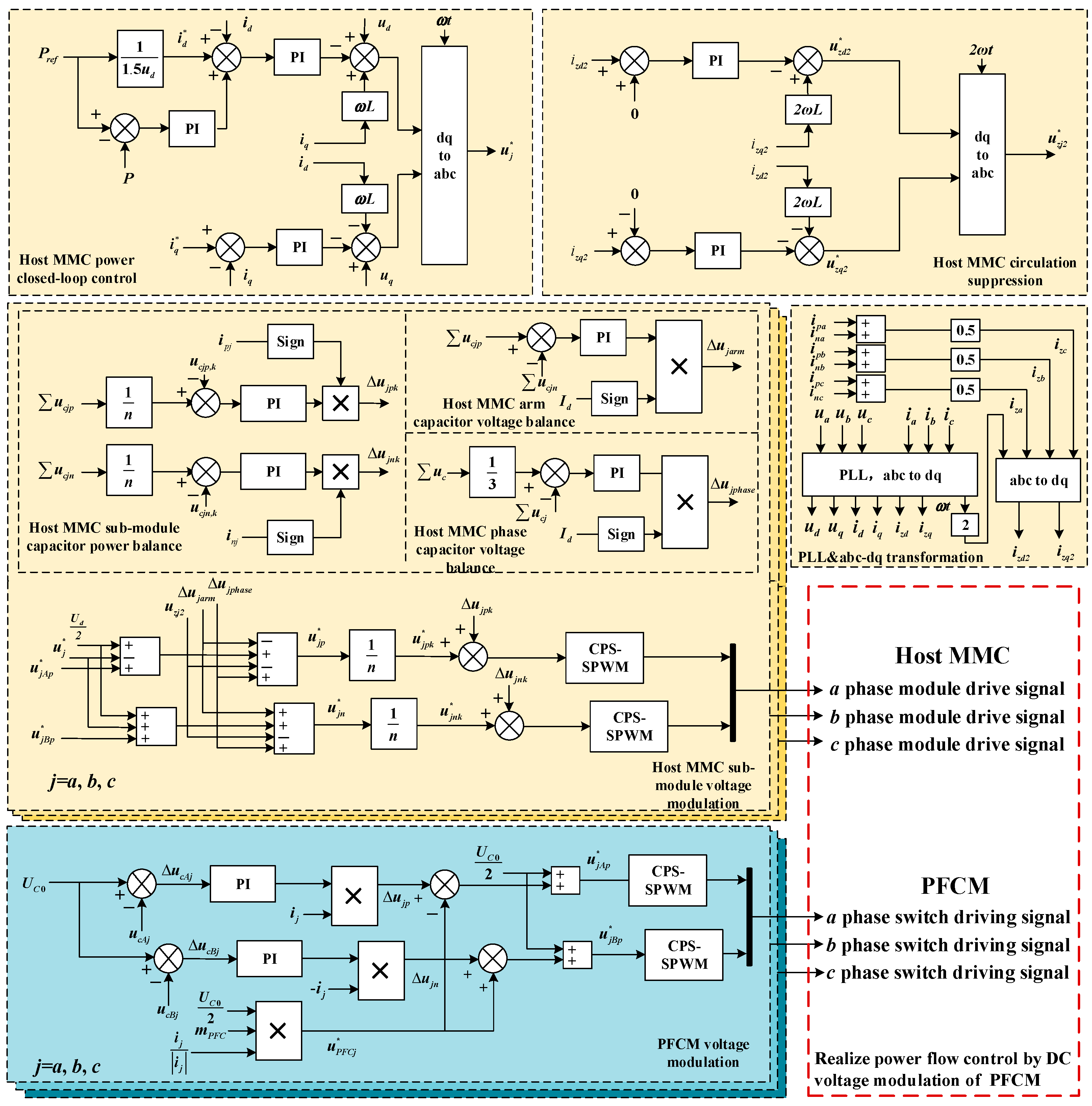
The overall control strategy of the M3C-PET contains two primary parts, the host MMC and PFCM control parts, as illustrated in Figure 4. In the M3C-PET, the MMC control part is responsible for regulating both active and reactive power. Similarly to conventional MMC applications, a multilayer energy balancing strategy and carrier-phase-shifted PWM modulation are applied in the host MMC control part to maintain the phase, arm, and SM energy balance [25].
To achieve flexible power flow adjustment, the voltage difference between the two DC ports can be determined through the command sent by the upstream power control center. The internal power balance of the M3C-PET is essential for maintaining stable output voltages under various operating conditions. Accordingly, an additional fundamental voltage can be introduced to stabilize the PFCM’s output voltages as per (13).
Taking PFCM-A as an example, the additional voltage in Phase-a is assumed as
Δ u a p = K a p sin ω t + β
where Kap is the amplitude of the fundamental voltage, and β is its phase shift.
The additional voltage will be superimposed on the reference values of the MMC upper arm voltage and the PFCM-A’s upper switch voltage.
u a A p = a 1 U d 2 b 1 e a p + Δ u a p u a p = a 2 U d 2 b 2 e a p Δ u a p
where a1, a2 and b1, b2 are the voltage coefficients of the MMC upper arm and the PFCM-A, respectively. And a1, a2 and b1, b2 have the following relationship.
a 1 + a 2 = 1 b 1 + b 2 = 1 .
The power exchanged between the host MMC and the PFCMs can be regulated by uap.
Δ p a p = Δ u a p i a p t = 1 4 I K a p cos 2 ω t + β φ 1 3 I d K a p sin ω t + β 1 4 I K a p cos β + φ
The per-cycle power variation can be expressed as
Δ p a p ¯ = 1 4 I K a p cos β + φ
From (24), the modulation degree of fundamental voltage can be fully used only when the phase angle β = −ϕ,. In this regard, the additional voltage should be in-phase or opposite-phase with the corresponding arm current to achieve the optimal interaction capability. The capacitor voltage difference is transferred to the PI controller as its input. The phase current of the host MMC is multiplied by the output of the PI controller to generate the reference value of Δuap. This reference voltage is compared with the triangular carrier wave to obtain the three-phase sinusoidal PWM signals for the PFCM. The closed-loop control ensures that the bus voltage of PFCM equals the DC voltage required for the power flow control of the system. Thus, the controllable power flow and internal power balance of the M3C-PET are achieved.

5. Simulation Verification

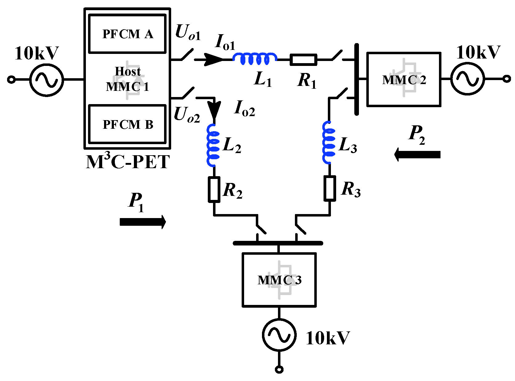
As shown in Figure 5, a simulation model of a 10 kV M3C-PET in a meshed DC system is established in MATLAB 2022b/Simulink to validate the feasibility and effectiveness of the proposed M3C-PET topology and its corresponding multilayer control strategy. In this figure, MMC 1 is retrofitted into the M3C-PET by adding two PFCMs.
Io1 and Io2 represent the output currents on the DC ports, while Uo1 and Uo2 denote the output voltages of the two DC ports. The system parameters are summarized in Table 1. The other system’s per-unit parameters are determined based on a reference benchmark, the DC line with rated capacity of 2 MVA and line voltage of 10 kV, to ensure consistency and accuracy in the simulation results.
In the simulation, MMC 3 maintains the DC voltage. The other two MMCs operate under power control mode. To verify the power flow controllability of the M3C-PET, three typical conditions are considered in the system.
Condition I (0~3 s): The output active power of the MMC converter station 1 is 1 MW. The PFCMs do not participate in the power flow adjustment, where the DC power flow is naturally dispatched according to the line impedances.
Condition II (3~6 s): The PFCMs joined the power flow control, where the active power of DC Ports 1 and 2 is regulated at 0.8 MW and 0.2 MW, respectively.
Condition III (6~9 s): The power flow of the DC Ports 1 and 2 is changed to 1.1 MW and −0.1 MW, respectively.
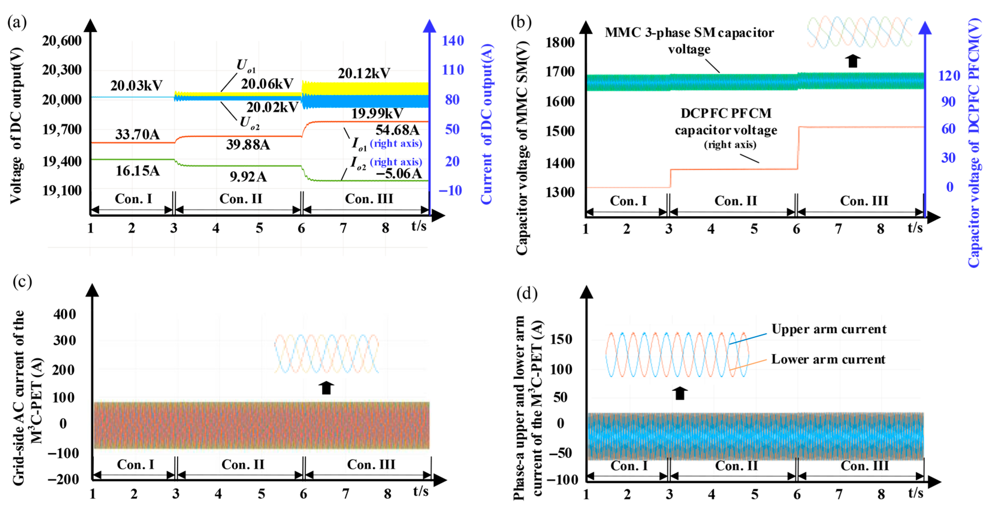
The simulation results are presented in Figure 6. Figure 6a shows the output voltages and currents of the M3C-PET, and their theoretical and simulation values are compared in Table 2. The simulation results of the output voltage are consistent with the theoretical values.
Figure 6b illustrates the capacitor voltage waveforms of a host MMC SM and the PFCM. In all three operating conditions, the SM capacitor voltage of the MMC remains stable. The SM capacitor voltage fluctuation is controlled within ±5% of the rated value, satisfying the design specifications. The theoretical and simulation values of the capacitor voltage are presented in Table 3. An average deviation of 0.3% can be found between the actual and theoretical values, proving the effectiveness of the proposed multilayer control strategy.
Figure 6c shows the grid-side AC current waveforms of MMC 1. The stable balanced currents indicate that the participation of the PFCM will not affect the power interaction of the host MMC’s AC port. Additionally, the balanced MMC arm current waveforms depicted in Figure 6d prove that the host MMC’s internal balance can be guaranteed during all three conditions.

6. Experiment Verification

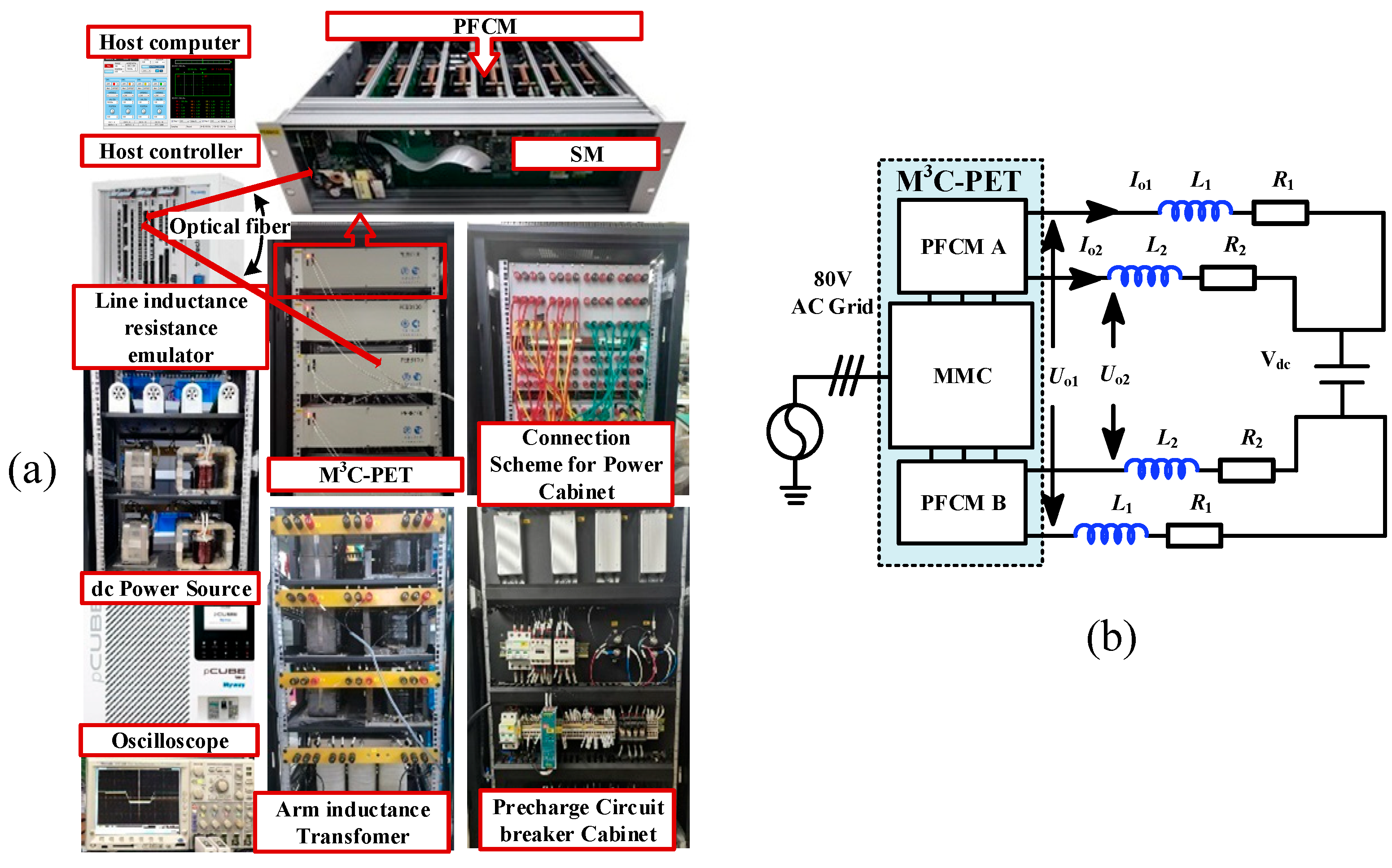
A scaled-down experimental prototype of the proposed M3C-PET and its testbed are constructed for verification, as shown in Figure 7a,b. In the experimental platform, the host MMC is connected to an 80 V AC voltage source, and the two DC grids are emulated by one DC voltage source with different line impedances. The corresponding experimental parameters are listed in Table 4. In the experiment, two operating conditions are considered to verify the feasibility and effectiveness of the proposed M3C-PET topology and control strategies.
Condition I: The host MMC transfers 1 kW active power from its AC side to the DC side. The PFCMs participate in the normal operation, and the power is evenly dispatched to the connected two lines with 0.5 kW.
Condition II: The PFCMs adjust the two DC lines’ active power to 0.7 kW and 0.3 kW, respectively.
The device operates under Condition I, where the DC lines’ power is initially regulated at 0.5 kW by the M3C-PET. And the system’s operation shifts to Condition II at 20 s.
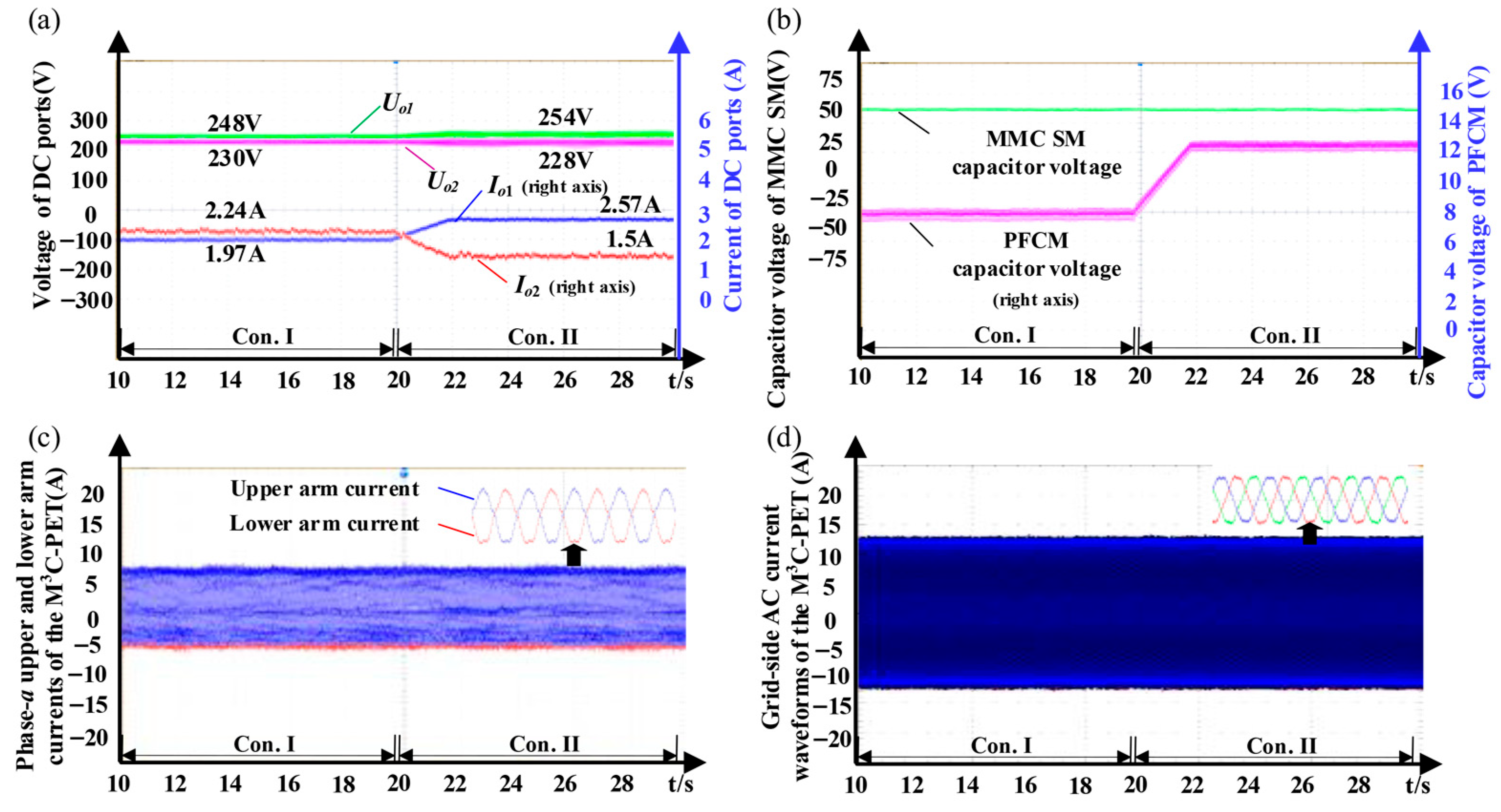
The experimental results are shown in Figure 8. Figure 8a illustrates the DC voltage and current waveforms at the outputs. The DC port voltages remain stable during the two conditions, while the currents are altered accordingly. To further quantify these observations, Table 5 lists the experimental voltage and current values under both conditions. The slight differences between the measured and theoretical values (evident in both Figure 8a and Table 5) confirm the power flow controllability of the M3C-PET. Figure 8b shows the capacitor voltages of the MMC SM and the PFCMs. The capacitor voltages of the MMC SMs are not affected by the operational condition alternation, proving the effectiveness of the proposed energy balance control. The MMC arm current waveforms are depicted in Figure 8c. The amplitude and phase angle of the MMC arm current remain stable throughout the process, ensuring the power balance between the upper and lower arms.
Figure 8d illustrates the AC grid current waveform, where its amplitude keeps constant under different conditions, indicating that the total power interaction between the AC and DC sides stays stable after the activation of the PFCMs. These experimental results confirm the performance of the M3C-PET and the multilayer energy balance control strategy.

7. Conclusions

This paper proposes an M3C-PET topology for the meshed DC grid. First, the proposed M3C-PET can realize flexible DC distribution line interconnection via small-capacity PFCMs. Combining the PFCM and the host MMC station, the corresponding external power supplies and isolation transformers are eliminated, reducing the system’s cost and volume significantly. Second, the proposed topology enables engineering adaptability by allowing retrofitting of existing MMC converters via direct PFCM embedding into the MMC arms, avoiding full infrastructure replacement and facilitating practical grid upgrading. The proposed topology can control power flexibly and unidirectionally through the corresponding multilayer control scheme, making it more competitive in large-scale renewable energy source applications. Two targeted directions will be considered in the future research: to overcome the current unidirectional power flow limitation, half-bridge submodules will be series-connected with PFCMs to extend controllability for broader bidirectional energy exchange scenarios, and modulation/control strategies for the M3C-PET variants will be further studied to adapt to extreme conditions and enhance grid resilience.

Author Contributions

Conceptualization, H.C. and J.Z.; methodology, J.Z. and W.W.; software, H.G. and G.Z.; validation, J.Z., G.Z. and C.Z.; formal analysis, H.C. and J.Z.; investigation, C.Z.; resources, W.C. and W.W.; data curation, W.C.; writing—original draft preparation, H.C.; writing—review and editing, J.Z.; visualization, H.G. and C.Z.; supervision, H.C. and J.Z.; project administration, J.Z. and W.C.; funding acquisition, H.C. and J.Z. All authors have read and agreed to the published version of the manuscript.

Funding

This research was funded by Guangdong Provincial Key Laboratory of Intelligent Operation and Control for New Energy Power System, grant number GPKLIOCNEPS-2024-KF-06.

Data Availability Statement

Data are contained within the article.

Conflicts of Interest

Author Haiqing Cai, Haohan Gu, Wencong Wu, and Wei Chen are employed by the company Guangdong Provincial Key Laboratory of Intelligent Operation and Control for New Energy Power System and China Southern Power Grid Electric Power Research Institute. The remaining authors declare that the research was conducted in the absence of any commercial or financial relationships that could be construed as a potential conflict of interest. The authors declare that this study received funding from Guangdong Provincial Key Laboratory of Intelligent Operation and Control for New Energy Power System (GPKLIOCNEPS-2024-KF-06). The funder had the following involvement with the study: design of the study, analysis and interpretation of data, and writing of the report.

References

  1. Van Hertem, D.; Gomis-Bellmunt, O.; Liang, J. HVDC Grids: For Offshore and Supergrid of the Future; Wiley-IEEE Press: Hoboken, NJ, USA, 2016; ISBN 978-1-118-85915-5. [Google Scholar]
  2. Radwan, M.; Azad, S. Protection of Multi-Terminal HVDC Grids: A Comprehensive Review. Energies 2022, 15, 9552. [Google Scholar] [CrossRef]
  3. Chen, Y.; Yu, S.; Wang, Y.; Yang, R.; Cheng, X. An Improved AC-Link Voltage Matching Control for the Multiport Modular Multilevel DC Transformer in MVDC Applications. Energies 2024, 17, 1346. [Google Scholar] [CrossRef]
  4. Zhu, X.; Hou, J.; Liu, L.; Zhang, B.; Wu, Y. A Modular Multiport DC Power Electronic Transformer Based on Triple-Active-Bridge for Multiple Distributed DC Units. IEEE Trans. Power Electron. 2024, 39, 15191–15205. [Google Scholar] [CrossRef]
  5. Gomis-Bellmunt, O.; Sau-Bassols, J.; Prieto-Araujo, E.; Cheah-Mane, M. Flexible Converters for Meshed HVDC Grids: From Flexible AC Transmission Systems (FACTS) to Flexible DC Grids. IEEE Trans. Power Deliv. 2020, 35, 2–15. [Google Scholar] [CrossRef]
  6. Wu, W.; Wu, X.; Wang, L.; Zhao, T.; Jing, L.; Li, J. Active Damping Control of Multiport DC Power Flow Controller for MMC-MTDC With Unbalanced AC Grid. IEEE J. Emerg. Sel. Top. Power Electron. 2021, 9, 7395–7407. [Google Scholar] [CrossRef]
  7. Zhang, X.; Jin, J.; Ye, Y.; Yang, X. Analysis of a Series-Parallel-Connected Type DC Power Flow Controller in Multiterminal Grids. IEEE Trans. Power Electron. 2022, 37, 7400–7410. [Google Scholar] [CrossRef]
  8. Sun, C.; Zhang, X.; Zhang, J.; Zhu, M.; Huang, J. Hybrid Input-Series–Output-Series Modular DC–DC Converter Constituted by Resonant and Nonresonant Dual Active Bridge Modules. IEEE Trans. Ind. Electron. 2022, 69, 1062–1069. [Google Scholar] [CrossRef]
  9. Wang, Y.; Zhang, Y.; Wang, Y.; Zhu, L.; Guan, Y.; Chen, S.-Z.; Zhang, G.; Yang, L. A Dual-Active-Bridge With Half-Bridge Submodules DC Solid-State Transformer for DC Distribution Networks. IEEE J. Emerg. Sel. Top. Power Electron. 2021, 9, 1891–1904. [Google Scholar] [CrossRef]
  10. Mehrabankhomartash, M.; Yin, S.; Kandula, R.P.; Divan, D.; Saeedifard, M. Analysis and Design Guidelines of the Isolated Modular Multilevel DC–DC Converter With the Impact of Magnetizing Inductance. IEEE Trans. Ind. Electron. 2023, 70, 11911–11922. [Google Scholar] [CrossRef]
  11. Li, B.; Wang, Y.; Jiao, Y.; Zhao, X.; Suo, Z.; Li, R.; Xu, D. Bidirectional Hybrid Isolated DC Transformer for All-DC Collection and Transmission System. IEEE Trans. Power Electron. 2025, 40, 11598–11615. [Google Scholar] [CrossRef]
  12. Kanaparthi, R.K.; Singh, J.P.; Ballal, M.S. A Review on Multi-Port Bidirectional Isolated and Non-Isolated DC-DC Converters for Renewable Applications. In Proceedings of the 2022 IEEE International Conference on Power Electronics, Drives and Energy Systems (PEDES), Jaipur, India, 14–17 December 2022; pp. 1–6. [Google Scholar]
  13. Rouzbehi, K.; Heidary Yazdi, S.S.; Shariati Moghadam, N. Power Flow Control in Multi-Terminal HVDC Grids Using a Serial-Parallel DC Power Flow Controller. IEEE Access 2018, 6, 56934–56944. [Google Scholar] [CrossRef]
  14. Mu, Q.; Liang, J.; Li, Y.; Zhou, X. Power Flow Control Devices in DC Grids. In Proceedings of the 2012 IEEE Power and Energy Society General Meeting, San Diego, CA, USA, 22–26 July 2012. [Google Scholar] [CrossRef]
  15. Jovcic, D.; Hajian, M.; Zhang, H.; Asplund, G. Power Flow Control in DC Transmission Grids Using Mechanical and Semiconductor Based DC/DC Devices. In Proceedings of the 10th IET International Conference on AC and DC Power Transmission (ACDC 2012), Birmingham, UK, 4–5 December 2012; pp. 1–6. [Google Scholar]
  16. Zhang, S.; Li, B.; Wang, W.; Zhang, Y.; Xu, D.; Li, G.; Liang, J. A Hybrid Modular Interline Current Flow Controller for Meshed HVDC Grids. IEEE Trans. Ind. Electron. 2022, 69, 10055–10065. [Google Scholar] [CrossRef]
  17. Barker, C.D.; Whitehouse, R.S. A Current Flow Controller for Use in HVDC Grids. In Proceedings of the 10th IET International Conference on AC and DC Power Transmission (ACDC 2012), Birmingham, UK, 4–5 December 2012; pp. 1–5. [Google Scholar]
  18. Sau-Bassols, J.; Prieto-Araujo, E.; Gomis-Bellmunt, O.; Hassan, F. Series Interline DC/DC Current Flow Controller for Meshed HVDC Grids. IEEE Trans. Power Deliv. 2018, 33, 881–891. [Google Scholar] [CrossRef]
  19. Zhong, X.; Zhu, M.; Li, Y.; Wang, S.; Wang, H.; Cai, X. Modular Interline DC Power Flow Controller. IEEE Trans. Power Electron. 2020, 35, 11707–11719. [Google Scholar] [CrossRef]
  20. Abbasipour, M.; Liang, X. Power Flow Study of MT-HVDC Grid Compensated by Multiport Interline DC Power Flow Controller. IEEE Trans. Ind. Appl. 2023, 59, 4786–4796. [Google Scholar] [CrossRef]
  21. Guo, H.; Chen, W.; Zhu, Y.; Zhu, M. An Expandable Interline DC Power Flow Controller. IEEE Trans. Power Electron. 2024, 39, 826–836. [Google Scholar] [CrossRef]
  22. Tuo, C.; Xu, Q.; Hu, J.; Guo, P.; Li, Y.; Xiao, M.; Guerrero, J.M. Decoupling and Phase Shift Control Method of Modular Interline DC Power Flow Controller. IEEE Trans. Power Deliv. 2024, 39, 661–674. [Google Scholar] [CrossRef]
  23. Zhong, X.; Zhu, M.; Chi, Y.; Liu, S.; Cai, X. Composite DC Power Flow Controller. IEEE Trans. Power Electron. 2020, 35, 3530–3542. [Google Scholar] [CrossRef]
  24. Yao, Z.; Lei, X.; Du, X. A Comprehensive Review of Condition Monitoring Technologies for Modular Multilevel Converter (MMC) HVDC Systems. Electronics 2025, 14, 3462. [Google Scholar] [CrossRef]
  25. Deng, F.; Liu, C.; Chen, Z. Control of MMCs. In Modular Multilevel Converters: Control, Fault Detection, and Protection; IEEE: Piscataway, NJ, USA, 2023; pp. 29–102. ISBN 978-1-119-87561-1. [Google Scholar]
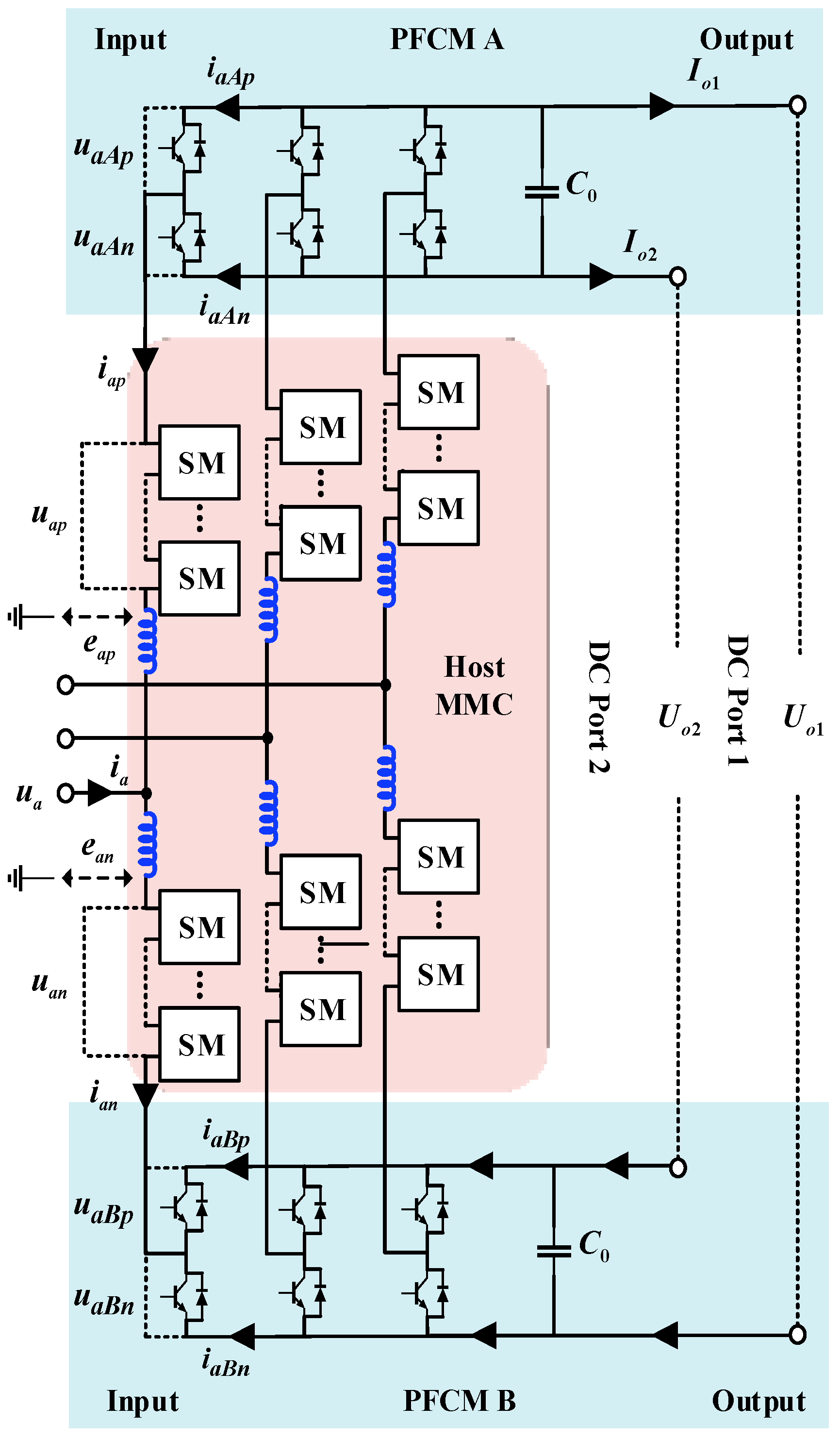
Figure 1. The proposed M3C-PET topology.
Electronics 14 04192 g001
Figure 2. Single-phase equivalent DC circuit of the M3C-PET.
Electronics 14 04192 g002
Figure 3. Single-phase equivalent ac circuit of the M3C-PET.
Electronics 14 04192 g003
Figure 4. Control strategy of the M3C-PET.
Electronics 14 04192 g004
Figure 5. Three-terminal meshed DC transmission system with the M3C-PET.
Electronics 14 04192 g005
Figure 6. Simulation results of the M3C-PET in different modes: (a) DC output voltage and current; (b) capacitor voltage of host MMC and PFCM; (c) grid-side AC current of the M3C-PET; (d) phase-a upper and lower arm current of the M3C-PET.
Electronics 14 04192 g006
Figure 7. (a) M3C-PET experiment system (b) M3C-PET experiment system circuit.
Electronics 14 04192 g007
Figure 8. Simulation results of the M3C-PET under different conditions: (a) DC output voltage and current; (b) capacitor voltage of the host MMC and PFCM; (c) phase-a upper and lower arm current of the M3C-PET; (d) grid-side AC current waveforms of the M3C-PET.
Electronics 14 04192 g008
Table 1. Parameters of simulation system.
ParameterValueParameterValue
MMC rated capacity2 MVAMMC switching frequency1 kHz
MMC rated AC line voltage10 kVMMC SM capacitor1.8 mF
MMC rated DC voltage20 kVMMC SM capacitor voltage1666 V
MMC SM number12MMC arm inductor0.050 p.u.
PFCM switching frequency1 kHzPFCM capacitor1.8 mF
Line1 resistor R10.060 p.u.Line1 inductor
L1
0.075 p.u.
Line2 resistor R20.040 p.u.Line2 inductor
L2
0.050 p.u.
Line3 resistor
R3
0.020 p.u.Line3 inductor
L3
0.025 p.u.
Table 2. Theoretical and simulation values of PFCM output voltage and current.
Condition IUo1/kVUo2/kVIo1/AIo2/A
Theoretical value20.0320.0333.3616.56
Simulation value20.0320.0333.7016.15
Condition IIUo1/kVUo2/kVIo1/AIo2/A
Theoretical value20.0620.0239.889.99
Simulation value20.0620.0239.889.92
Condition IIIUo1/kVUo2/kVIo1/AIo2/A
Theoretical value20.1219.9954.68−5.00
Simulation value20.1219.9954.68−5.06
Table 3. Theoretical and simulation values of the PFCM capacitor voltage.
Condition ICondition IICondition III
Theoretical value of UC00 V19.6 V64.2 V
Simulation value of UC00 V19.6 V64.0 V
Table 4. Parameters of the experimental system.
ParameterValueParameterValue
MMC rated capacity2 kVAMMC SM switching frequency1 kHz
MMC rated AC line voltage120 VMMC SM capacitor1.8 mF
MMC rated DC voltage240 VMMC SM bus voltage60 V
MMC SM number4MMC arm inductor2 mH
PFCM switching frequency1 kHzPFCM capacitor1.8 mF
Line1 resistance R15 ΩLine1 inductance
L1
1.2 mH
Line2 resistance R21 ΩLine2 inductance
L2
1.2 mH
DC voltage source Vdc220 V
Table 5. Theoretical and experimental values of PFCM output voltage and current.
Condition 1Uo1/VUO2/VIO1/AIO2/A
Theoretical Value2412242.082.23
Experimental Value2482301.972.24
Condition 2Uo1/VUO2/VIO1/AIO2/A
Theoretical Value2482232.721.35
Experimental Value2542282.571.50
Disclaimer/Publisher’s Note: The statements, opinions and data contained in all publications are solely those of the individual author(s) and contributor(s) and not of MDPI and/or the editor(s). MDPI and/or the editor(s) disclaim responsibility for any injury to people or property resulting from any ideas, methods, instructions or products referred to in the content.