Article

Acoustic Emission from GaN-on-Sapphire Structures

by
Bartlomiej K. Paszkiewicz
*,
Bogdan Paszkiewicz
and
Andrzej Dziedzic
Faculty of Electronics, Photonics and Microsystems, Wroclaw University of Science and Technology, 27 Wybrzeze Stanisława Wyspianskiego St., 50-370 Wroclaw, Poland
*
Author to whom correspondence should be addressed.
Electronics 2025, 14(21), 4146; https://doi.org/10.3390/electronics14214146
Submission received: 18 July 2025 / Revised: 15 October 2025 / Accepted: 20 October 2025 / Published: 23 October 2025
(This article belongs to the Section Electronic Materials, Devices and Applications)

Abstract

This paper presents a study on the propagation of acoustic waves in gallium nitride (GaN) layers deposited on sapphire substrate. The influence of GaN layer thickness and the configuration of interdigital transducers (IDTs) on the generation and propagation of different surface wave modes, including Rayleigh, Sezawa, and Love waves, was analyzed. Experimental measurements in the 100 MHz–6 GHz range were complemented by numerical simulations using the finite element method (FEM). The results demonstrated a strong dependence of wave characteristics on technological parameters, particularly the quality of the GaN–sapphire interface. The data obtained can be utilized for optimizing the design of acoustic sensors, resonators, and RF filters.

1. Introduction

Gallium nitride is one of the most significant semiconductor materials. A key factor contributing to its uniqueness is its wide range of applications [1,2,3,4]. Nitride layers are widely used in optoelectronic and electronic devices, such as LEDs, lasers, microwaves, and high-power devices. Nitrides are also being increasingly applied in emerging fields such as spintronics and low-dimensional transistors. In addition to conventional semiconductor applications, nitrides are valuable due to their piezoelectric properties [5]. In particular, nitride layers on sapphire are well-suited for such applications. This is because sapphire has a high intrinsic Q factor and low dielectric losses [6,7]. Its presence enables the use of nitrides in the fabrication of passive electroacoustic components, such as resonators and filters, as well as sensor elements (force, pressure, temperature, and gas sensors). The literature on the propagation of surface waves in nitride layers on sapphire is extensive [8,9,10,11,12,13,14]. However, the details of surface wave propagation in multilayer systems strongly depend on the precise technological parameters of the layer growth process. The deposition of AIIIN nanostructures on heteroepitaxial substrates requires the use of GaN nucleation layers deposited at low temperatures (approximately 550–700 °C). The crystallization conditions (pressure) and annealing process of the nucleation layer (pressure, temperature ramp profile) determine the size of the crystallites from which bulk GaN growth occurs, significantly influencing the mechanical properties of the GaN layer. Unlike other materials, the technological process of GaN layer fabrication on sapphire substrates cannot be separated from the final parameters of the fabricated transducers. Additionally, most of the particular wave modes result from interactions within the multilayer system, as acoustic waves propagate both in the nitride layer and the sapphire substrate. Therefore, existing literature sources do not comprehensively describe all the possible modes of propagation and are mostly over ten years old. Given the rapid development of metalorganic vapor phase epitaxy (MOVPE) technology, conducting updated investigation is necessary. Improved epitaxial methods primarily enable the growth of layers with superior crystallographic properties, more stable process-to-process parameters, and enhanced mechanical characteristics. This progress has been made possible by the techniques described in the following sections, which effectively mitigate the impact of lattice mismatch. Previous studies on the application of surface acoustic waves (SAWs) in GaN structures encountered limitations arising from the quality of the grown layers. While their parameters were sufficient for the fabrication of electronic and optoelectronic devices, in acoustic applications, the lattice mismatch resulted in low efficiency of the fabricated transducers and a large variability of their parameters, particularly due to fluctuating mechanical properties. Moreover, the integration of transducers with other active elements fabricated on the same layer was hindered by the constraints of lithographic and etching technologies. Recent advancements in this field, however, open new possibilities for the integration of SAW devices with active components within monolithic structures. An additional reason for this is study is that most of the existing literature focuses on specific types of layers and particular propagation modes, but a comprehensive analysis over the entire frequency range and the strong dependence of mode characteristics on layer thickness and electrode spacing is lacking. This paper presents a comprehensive analysis of acoustic wave propagation excited by interdigital transducers in gallium nitride layers on sapphire.

2. Materials and Methods

2.1. Test Structures

To analyze the propagation of acoustic waves in the nitride heterostructure deposited on sapphire, interdigital transducers (IDTs) were fabricated. Table 1 presents the configurations of the fabricated transducers.
The transducers were fabricated in pairs, positioned opposite each other at distances of d = 1, 2, or 5 mm. The structures were arranged in parallel lines. Configuration “01” means that we have alternating digits connected to either ground or source, while configuration”0011” means that digits are connected to ground and source in pairs. Later configurations reduce the inter-digit reflectance between digits as reflected waves from each digit are opposite in phase and cancel each other. They were fabricated on undoped GaN layers of varying thickness. Additionally, to verify the influence of electrical (capacitive) interactions on acoustic interactions, identical interdigital structures were fabricated directly on the sapphire substrate, which lacked piezoelectric properties.
The epitaxial layers were grown using the MOVPE (Metalorganic Vapour Phase Epitaxy) technique on two-inch (0001)-oriented sapphire substrates in an AIXTRON CCS 3 × 2″ epitaxial system (AIXTRON SE, Herzogenrath, Germany). Crystallization took place at a pressure of 100 mbar in a hydrogen atmosphere. Trimethylgallium (TMGa) was used as the gallium source, while NH3 (ammonia) served as the nitrogen source. For the study, a fundamental structure commonly used in GaN-based electronic devices was selected—an undoped GaN buffer layer with thicknesses of 2 μm, 4 μm, and 6 μm grown at 1045 °C. Prior to material growth, C-plane sapphire substrate was thermally cleaned for 10 min in 1100 °C. After that, the sapphire surface was NH3 treated in 540 °C for 3 min, and the LT-GaN nucleation layer (50 nm thick) was deposited. The nucleation layer was annealed with a temperature ramp from 540 to 1045 °C. The temperature increase time was 540 s. Highly resistive HT-GaN (high temperature GaN) buffer layer (250 nm) was grown in 1045 °C at 100 mbar with V/III ratio equal to 2400 and 1700 nm (3700 nm and 5700 nm GaN layers were subsequently deposited on top of the structure in 1045 °C at 100 mbar with V/III ratio equal to 1200). This optimized growth procedure allowed for the growth of monocrystalline GaN of high quality with a surface roughness of Rrms = 0.59 nm (based on AFM measurement) [1]. An AFM picture is presented in Figure 1a, and the simplified layer layout is presented in Figure 1b.
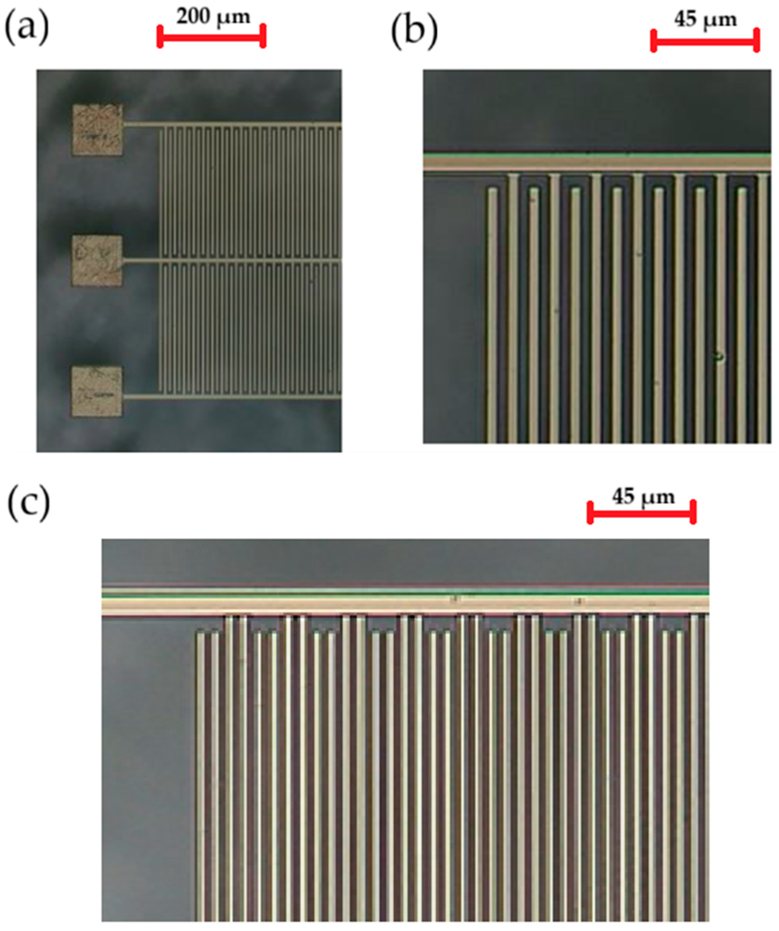
The interdigital transducers were fabricated using the photolithography process. The fingers, serving as ohmic contacts, were produced using the lift-off metallization technique with a Ti/Al/Mo/Au stack [2,3]. The images presented in Figure 2a,b show the fabricated structures.

2.2. Measurements

The measurements of the interdigital transducers were conducted using the “on-wafer” method with Picoprobe GSG (GGB Industries, Inc., Naples, FL, USA) (ground-signal-ground) microwave probe tips, which had a 250 μm spacing between the contact pads. A four-port Agilent N5230A (PNA-L Network Analyzer, Agilent, Santa Clara, CA, USA) was used, along with Sucoflex 100 measurement cables from Suhner (HUBER+SUHNER AG, Herisau, Germany). The network analyzer was calibrated using a Picoprobe ceramic substrate (GGB Industries, Inc., Naples, FL, USA) with CS-8 calibration structures. Measurements were performed over a wide frequency range (100 MHz–6 GHz) as well as in narrower bands corresponding to specific modes of generated acoustic waves. The samples and probe tips were placed in a Cascade Microtech MPS150 probe station (Casade Microtech, Beaverton, OR, USA). The primary challenge in measuring the interdigital transducers was ensuring measurement accuracy. The resonance frequency transmission peaks varied between −30 dB and −70 dB, while the observed reflection peaks were on the order of tenths of a dB. The subtle nature of the transmission spectra required a possible large number of frequency points and narrow bandwidth settings for the network analyzer’s detectors. However, narrowing the detector bandwidth and increasing the number of measurement points significantly increased measurement time. A compromise between measurement time and noise level was achieved with a detector bandwidth of 200 kHz and a measurement signal power of 0 dBm. Obtaining accurate and reliable measurement results for the interdigital transducers required a detailed preparation procedure for the measurement setup. Before starting the measurements, the network analyzer was warmed up for approximately 2 h in a climate-controlled room. All measurement cables were secured to prevent accidental movement or deformation. The SOLT calibration method with the additional “isolation” option was then performed before structures were measured. Due to measurement system drift, minor distortions in the measured characteristics appeared after approximately 2 h, but they did not affect the correct interpretation of results. The calibration accuracy remained acceptable for several days, provided that the measurement system was properly warmed up and the room temperature remained stable.

3. Results

3.1. Identification of Acoustic Modes

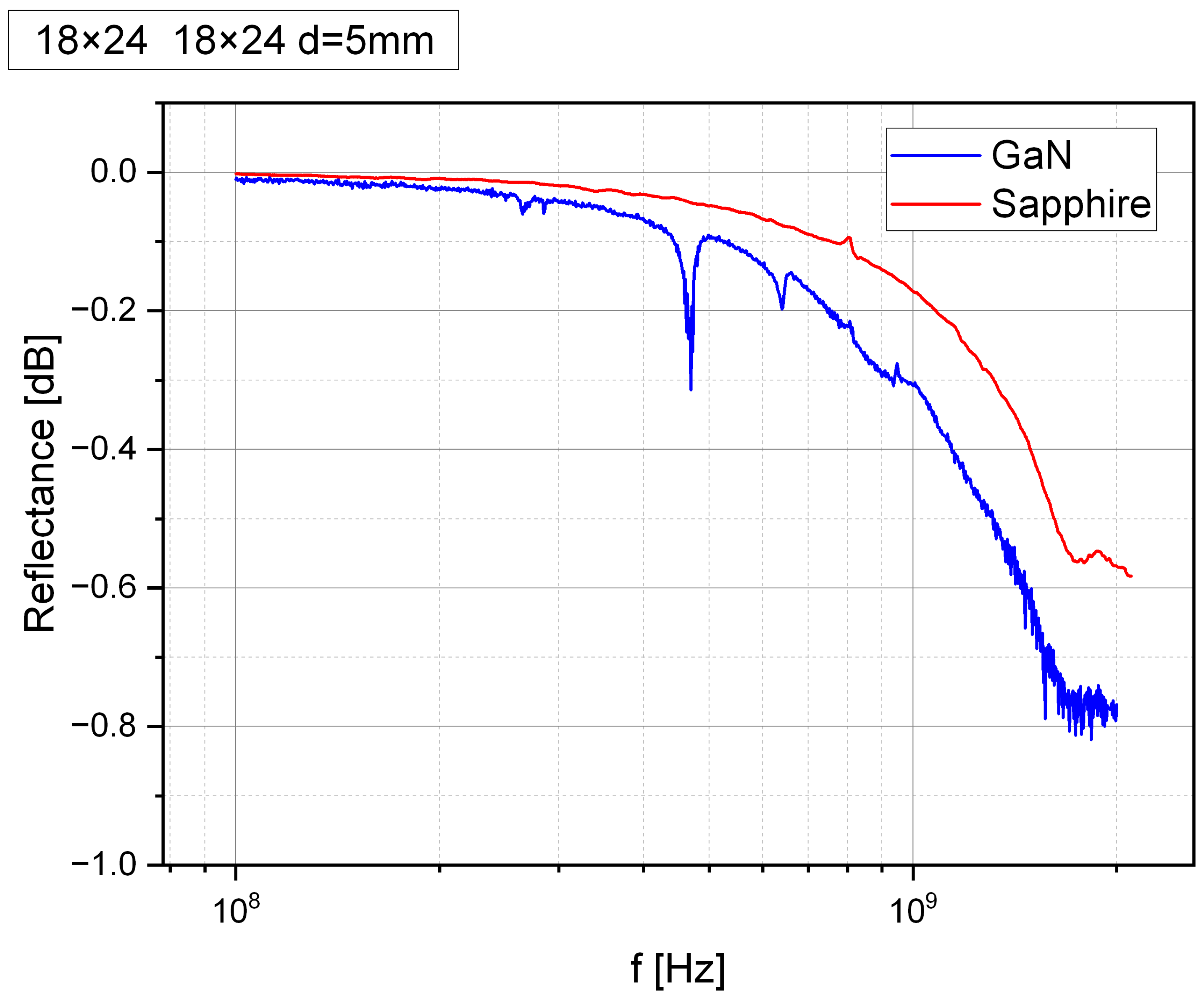
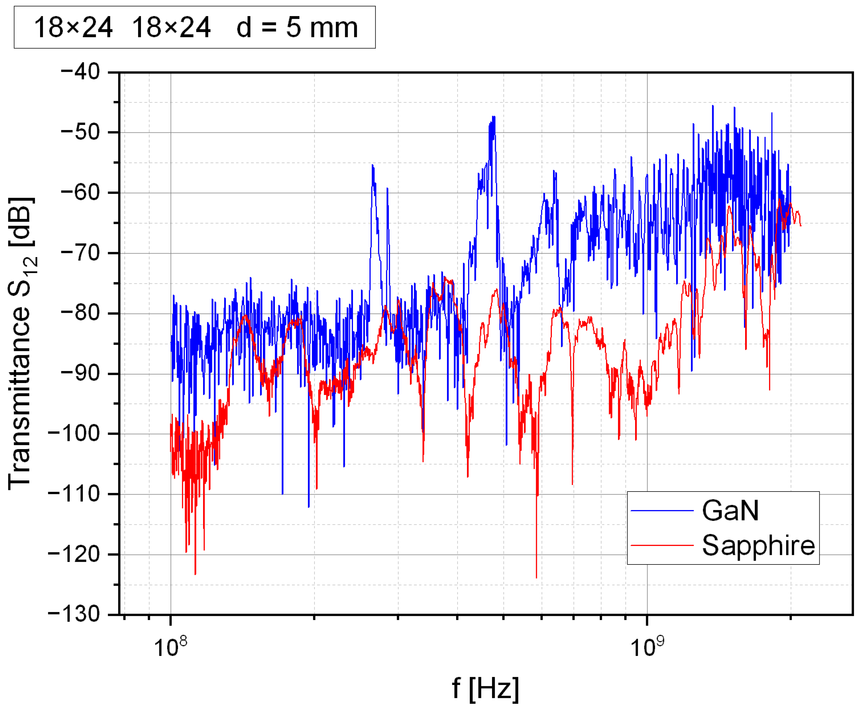
An example of the transducer’s reflectance characteristic (λ = 18 μm, N = 24), fabricated on a 2 μ thick GaN layer as well as directly on sapphire substrate, which is not a piezoelectric material, is shown in Figure 3. Additionally, Figure 4 below presents an example of transmittance (λ = 18 μm and N = 24) for both the GaN piezoelectric layer and directly on the sapphire substrate.
By comparing both characteristics, we observed significantly higher transmission values for transducers fabricated on GaN. The average transmission improved from −85 dB to −75 dB, with local resonances reaching a maximum of −42 dB. Similarly, the reflection characteristic indicates resonance regions, where a decrease in reflection occurs due to the conversion of electrical energy into an acoustic wave. The maximum local change in reflection was 0.3 dB. The difference in the relative magnitudes of peaks (or dips) in the reflectance and transmittance characteristics is attributed to the electrical mismatch between the 50 Ω probe and the interdigital transducers. Although only a small portion of the electrical energy was converted into acoustic waves, this energy propagated with low losses and was thus clearly visible in the transmittance characteristics. The analysis of these characteristics allowed for the identification of the following propagation modes—Rayleigh waves (including higher harmonics), Sezawa waves, Love waves, and pseudo-bulk waves. Among these, Rayleigh waves have the lowest propagation velocity but offer high Q factors and low propagation losses. In multilayer structures, the velocity of the Rayleigh mode depends on the thickness ratio of the layers and their physical parameters. When analyzing layered structures composed of different materials, a key parameter is the ratio of layer thickness to the transducer finger spacing, as it determines part of the wave that propagates in each layer. This relationship is described by the KH coefficient, which is the product of the wave vector (K) and the layer thickness (H), forming a dimensionless quantity. The wave vector K is defined by the following equation (Equation (1)):
K = 2 π λ ,
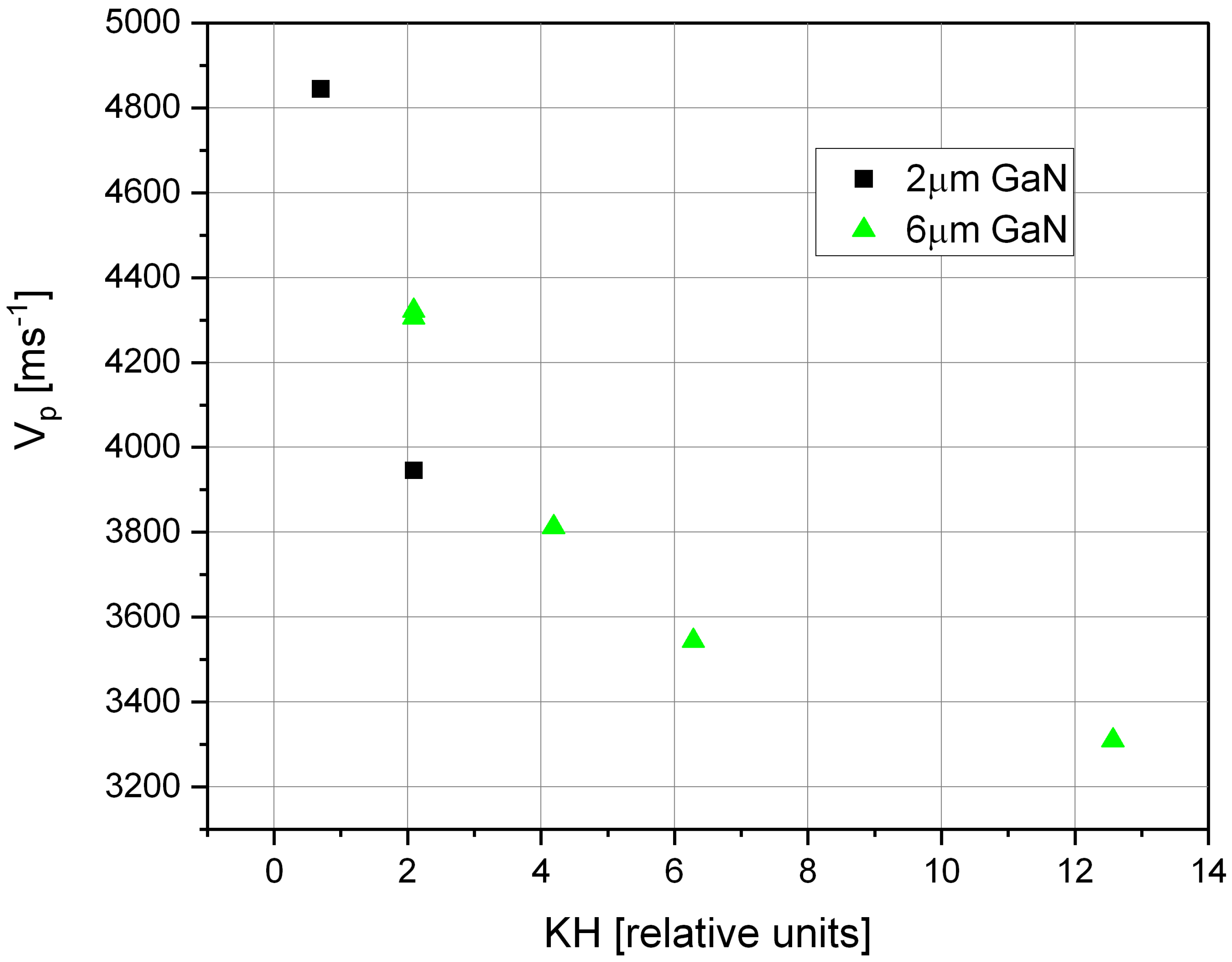
One way to increase the operating frequency of the transducer for a given finger spacing is to utilize higher harmonics. Due to the changing KH coefficient for these harmonics, the proportions between individual peaks are not maintained, as the acoustic wave propagation velocity varies. By comparing transducers with different finger spacings fabricated on GaN layers of varying thicknesses and analyzing successive harmonics, it was possible to determine the dispersion characteristic of the Rayleigh mode propagation velocity as a function of the KH coefficient, as presented in Figure 5:
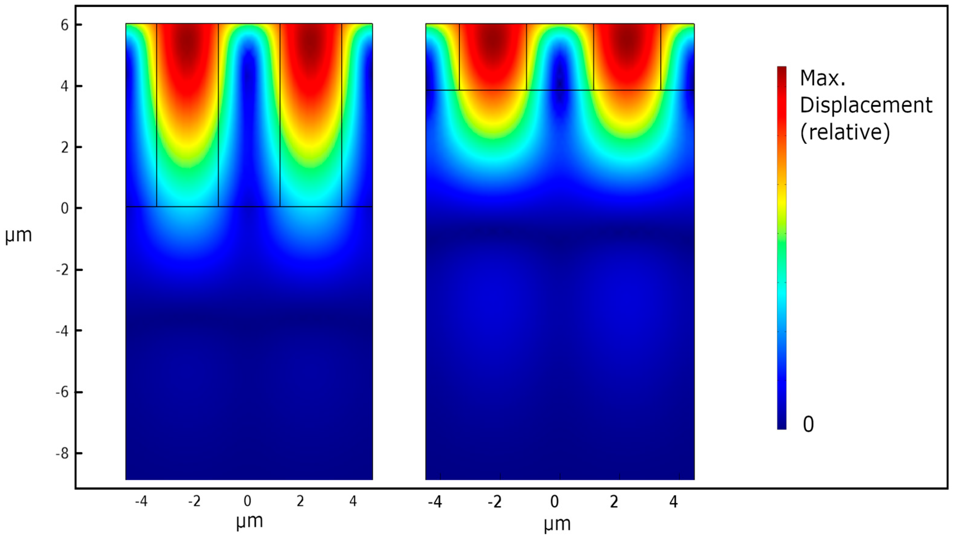
The smaller number of determined points for 2 µm layer results was due to the fact that for this layer, we observed much higher propagation velocities (since there was a larger part of the acoustic wave propagates in sapphire). Considering that the dimensions of the transducers were fixed independently of the layer thickness, this resulted in fewer successive Rayleigh wave harmonics being observable within the measured frequency range. The propagation velocity of the wave varied from the Rayleigh wave velocity in sapphire (for KH close to zero) to values corresponding to the propagation velocity in GaN. In GaN layers, the bulk wave velocity was lower than that in sapphire. To explain the obtained Rayleigh mode dispersion characteristics, a finite element simulation (FEM) of the GaN–sapphire multilayer system was conducted. The simulation was performed using Comsol Multiphysics (Version 4.4) [4]. The domains selected were piezoelectric material for GaN and linear elastic material for sapphire. The electrodes coating material influence was omitted to focus on qualitative differences between different layer thicknesses and propagation modes. Typically, including such layers in the simulation results in a decrease in the simulated propagation velocities. Equations describing domains behavior were linear. The 2D model definition was applied, as the sixfold crystallographic symmetry of sapphire and GaN material properties were the same in any direction parallel to surface. This allowed for a significant reduction of mesh density and computation time. A periodic boundary condition was applied, enforcing symmetry of the deformation field with respect to the left and right edges of the structure. This simulated the behavior of a transducer with an infinite number of fingers. The material parameters were taken from available literature sources [5,6,7] and are presented in Table 2 and Table 3. The simulation results are presented in Figure 6.
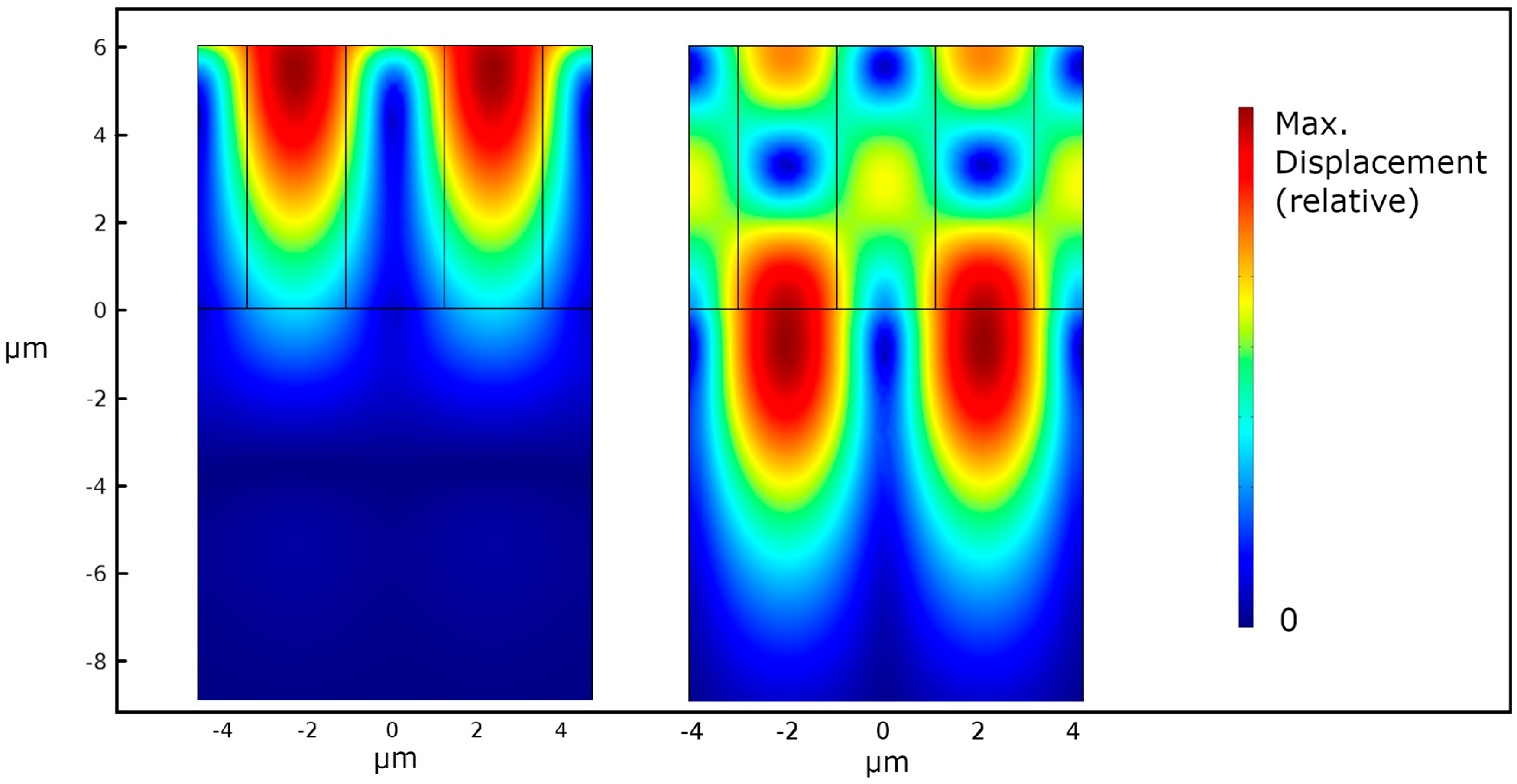
It can be observed that the deformation field gradually decreased with increasing distance from the surface. For a relatively high KH value of four for the 6 μm layer, most of the acoustic energy remained within the GaN layer. However, a portion of the acoustic wave energy propagated into the sapphire substrate. The simulated propagation speed for such layer was 3915 ms−1. Due to the higher acoustic wave propagation speed in sapphire compared to GaN, the phase velocity of the Rayleigh mode (and other modes) decreased asymptotically as the nitride layer thickness increased [8]. For thin GaN layers, the phase velocity remained close to that of sapphire since a larger portion of the wave propagated within the substrate, as can be seen on the right part of the figure. For the thinner layer (2 μm), the simulated propagation speed was 4700 ms−1. In the comparison of measured velocities, simulated ones and literature data for samples with KH ≥ 4, a significantly lower Rayleigh wave velocity was observed in measured samples than expected for monocrystalline GaN [9]. This can be attributed to LT-GaN layers being used as the nucleation layer in the epitaxy process. This highly defective layer helped in increasing the quality of subsequently deposited ones. Details of the process with AFM and SEM images are provided in other literature publications [1]. To design a high-performance transducer (with maximum operating frequency and high-quality factor Q), a balance must be struck between opposing factors. First, increasing GaN thickness enhances interdigitated transducer (IDT) coupling due to a larger active piezoelectric region. On the other hand, decreasing GaN thickness allows for a larger part of acoustic wave propagation inside the sapphire substrate, which is beneficial due to sapphire’s superior properties. Simultaneously, technological advancements must enable higher-quality GaN layers, ensuring a defect-free GaN–sapphire interface. It is important because defects reduce stiffness, which in turn lowers propagation velocity, impacting overall device performance. A unique feature of the GaN-on-sapphire multilayer system is the presence of Sezawa modes. Sezawa waves, due to their higher propagation speed compared to Rayleigh waves, allow for higher operating frequencies at the same characteristic transducer dimensions. This makes them an attractive candidate for SAW devices [10,11]. Their existence is possible due to the lower propagation velocity in GaN compared to the sapphire substrate. For Sezawa modes to propagate, the GaN layer has to be sufficiently thick (greater than KH = 4). According to theoretical models [12], the disappearance of Sezawa modes as the GaN layer becomes thinner is due to the increasing wave velocity and deeper penetration into the substrate. Eventually, the surface wave transitions into a shear bulk wave. For GaN on sapphire structures, Sezawa modes appear for KH > 4. In the experiment, for transducers with a finger spacing of λ = 9 μm, this corresponds to a GaN layer thickness of approximately 5.7 μm [9,12]. Figure 7 presents finite element method (FEM) simulation results for the same layer system, illustrating the comparison between total strain field distribution for Rayleigh and Sezawa mode propagation.
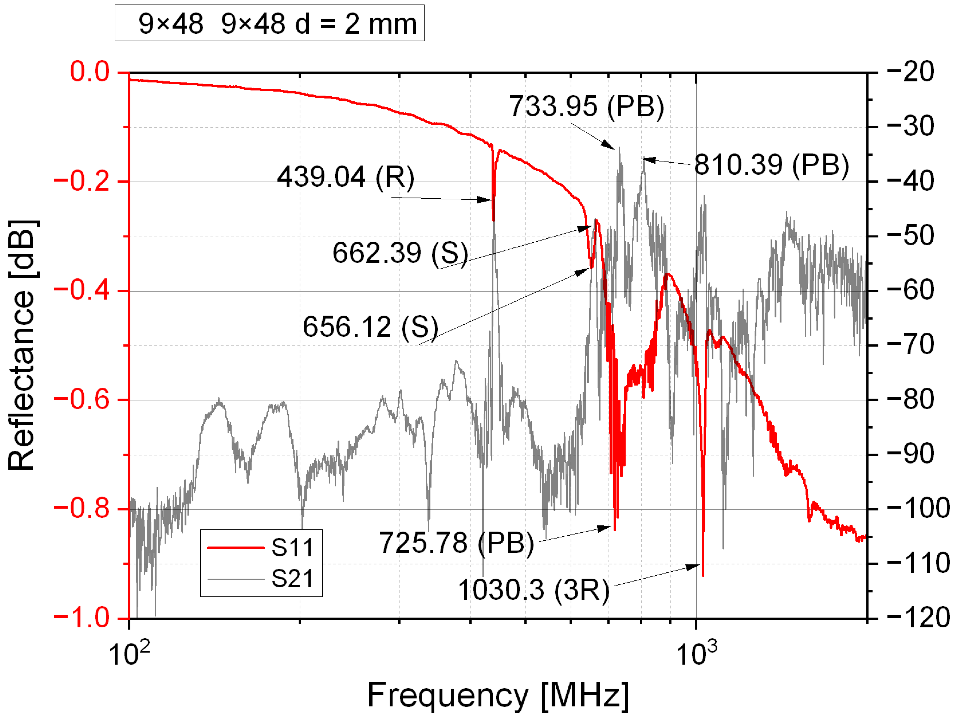
The primary difference between the Sezawa mode and the Rayleigh mode is the location of maximum strain. Rayleigh waves exhibit maximum strain at the surface of the GaN layer. Sezawa waves, on the other hand, reach their maximum strain deeper, near the GaN–sapphire interface. Sezawa modes are often mistaken for higher harmonics of Rayleigh modes, but they are fundamentally different propagation modes [13]. Unlike Rayleigh harmonics, Sezawa waves exist only in multilayer systems. Due to their deeper penetration into the substrate, Sezawa waves propagate at higher velocities than do Rayleigh ones, making them particularly useful in high-frequency SAW devices. For the simulated layer, the Sezawa mode velocity is 5895 ms−1. Analysis of the measured transmission and reflection characteristics revealed the presence of Sezawa modes even for layers with a lower KH coefficient. Figure 8 below presents the transmittance and reflectance for the interdigital transducer (λ = 9 μm) on a GaN layer of 4 μm thickness, corresponding to the KH coefficient of 2.8.
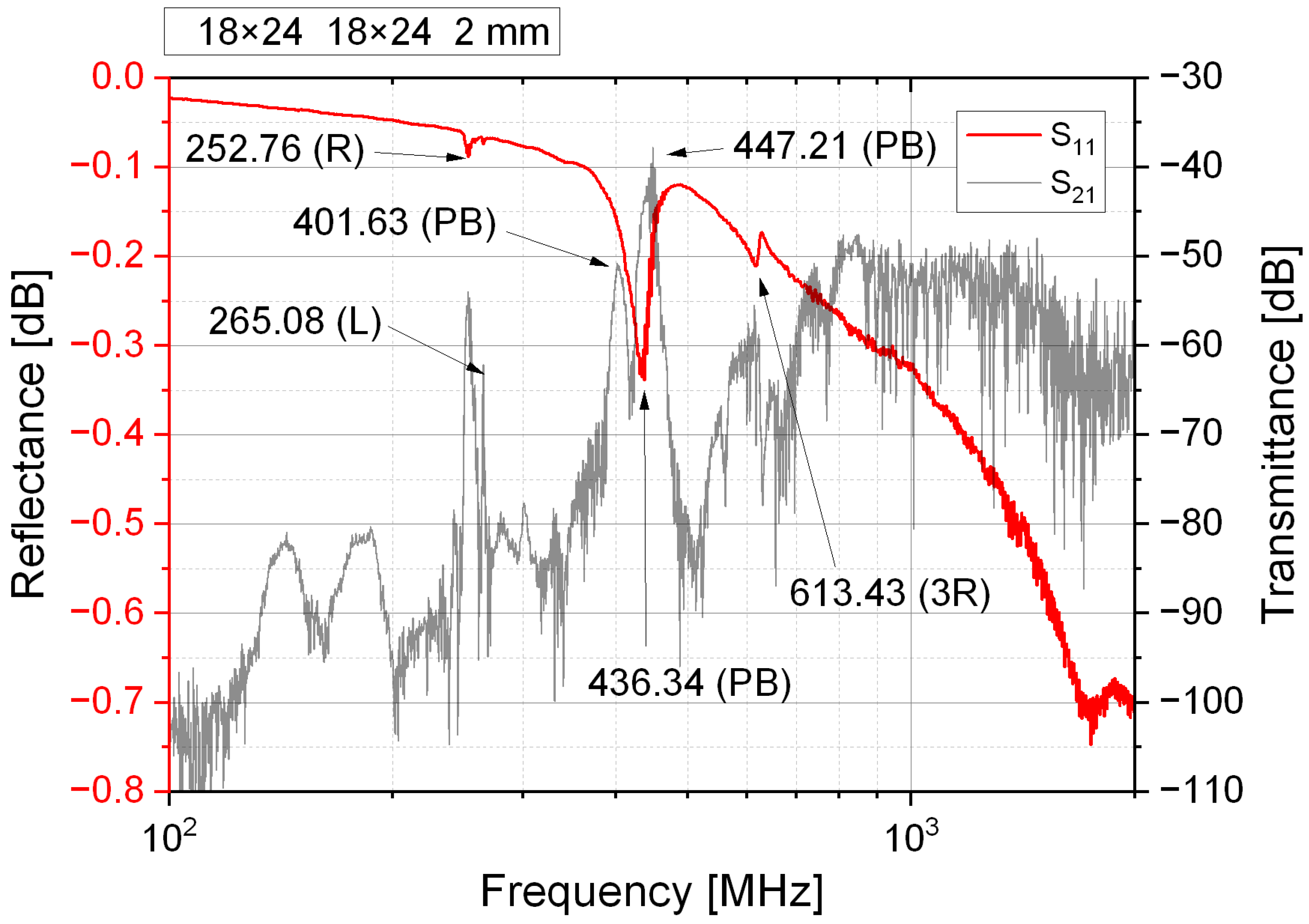
The Sezawa mode is observed at 662.39 MHz, as evidenced by a distinct dip in the reflection coefficient (S11) and corresponding changes in the transmission coefficients (S12 and S21). This dip appears just below the strong but broadband couplings associated with pseudo-bulk (PB) waves, confirming the presence of the Sezawa mode. At this frequency, the propagation velocity (Vp) is 5958 m/s, which is slightly lower than the shear wave velocity in sapphire. The calculated velocity further supports the identification of this dip as a Sezawa mode; in contrast, Rayleigh mode harmonics would exhibit a propagation velocity that is too low to be physically feasible. According to theoretical literature sources [12,15], the Sezawa mode is one of the few possible modes in such a multilayer system. This observation is consistent with the dispersive nature of the Sezawa mode, where a lower KH coefficient leads to a gradual transition into a bulk wave. The occurrence of the Sezawa mode at lower KH values could be attributed to two factors—lower actual stiffness of the GaN layer compared to the values used in simulations [9] or to presence of an interfacial layer with distinct material properties between the GaN layer and the sapphire substrate, which could facilitate acoustic wave confinement within the GaN layer. To further clarify these findings, Figure 9 presents the frequency characteristics of IDTs with λ = 18 μm, corresponding to a KH coefficient of 1.4.
The Sezawa mode merged with the broadband pseudo-bulk waves in the 401 MHz to 447 MHz range, as no distinct break can be observed at a frequency higher than the Rayleigh wave frequency (265.08 MHz). Both Sezawa and Rayleigh waves exhibit polarization perpendicular to the substrate. Another type of surface wave with a different polarization behavior is the SH (shear-horizontal) wave, where the material oscillations occur in a transverse direction. Such waves propagate with low losses over long distances. Unlike Rayleigh modes, they are less dependent on the pressure applied to the surface of the sample. This makes them an interesting propagation mode for biological sensor applications. In such sensors, the measured substance is often in liquid solutions [16,17]. In sensors utilizing shear vertical (SV modes (e.g., Rayleigh), there is a strong interaction between the vertically oscillating surface of the sample and the liquid, which makes it difficult to accurately detect the mass of the substance being measured. In sensors that utilize SH waves in their operation, this effect does not occur [18]. However, these waves are more difficult to obtain for a given transducer configuration due to the direction of the piezoelectric effect in nitrides (perpendicular to the surface) [19]. However, a special type of SH surface wave, which can occur in nitrides deposited on sapphire, is the Love wave. Their occurrence is made possible by the presence of a waveguide. They only occur in layered systems where the upper material layer has a lower phase velocity compared to the substrate material. The phase velocity of the Love mode for GaN layers on sapphire lies between the phase velocity of the Rayleigh mode and the velocity of the transverse bulk wave. Piezoelectric generation of Love modes, which are SH modes in nitride layers, is possible through the conversion of modes in the sapphire substrate [9]. Figure 10 shows the measurement results of the characteristics of structures with a λ = 18 μm mode made on a 4 μm thick layer, showing the occurrence of the Love mode.
It can be concluded that this is a Love mode due to its frequency being similar to that of the Rayleigh mode and the narrowband nature of the coupling [19]. It is characterized by a lower change in transmission at the peak compared to the Rayleigh mode by 7 dB, but its half-power bandwidth is 2 MHz, which is significantly smaller than the half-power bandwidth of the Rayleigh mode, which is 10 MHz. Increasing the operating frequency of the transducer with given dimensions leads to the conversion of surface waves into pseudo-bulk waves. The wave propagating along the substrate also partially penetrates into the substrate. These waves have a broader bandwidth and enable operation at higher frequencies. They can be distinguished by high dispersion and the presence of various modes. Details on pseudo-surface waves are presented in another study [20].

3.2. Analysis of Resonance, Antiresonance, and Electromechanical Coupling

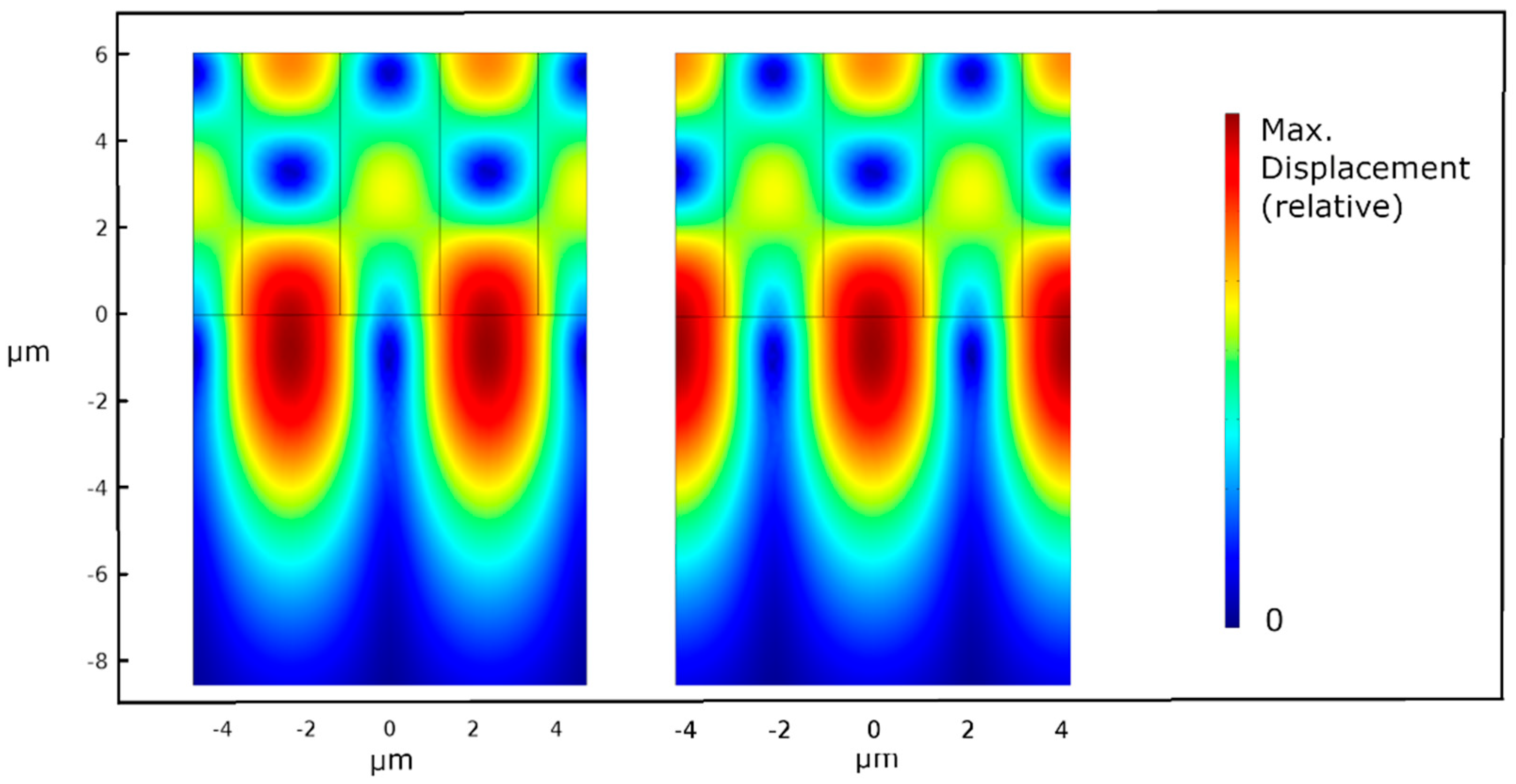
According to the theory of surface wave propagation in multilayer systems, for each frequency corresponding to the Rayleigh and Sezawa modes—characterized by the resonance of the interdigital transducer (IDT)—there exists an antiresonance condition, where the electrical and mechanical excitation phases are opposite. Figure 11 presents the displacement fields for both resonance and antiresonance of the Sezawa mode.
Analysis of resonance and antiresonance frequencies enabled the calculation of the electromechanical coupling coefficient (k2), a critical parameter for determining both the efficiency of acoustic wave generation and the sensitivity of surface acoustic wave (SAW) devices. This parameter was determined from resonance and antiresonance frequencies using the following relation (Equation (2)) [19,21]:
k 2 f a 2 f r 2 f a 2
where fr is the resonance frequency and fa is the antiresonance frequency. Table 4 summarizes the calculated k2 values for different modes and layer thicknesses.
These results align with literature reports for GaN thin films. Woods and Boroumand [22] reported k2 values of approximately 0.066% for GaN films with KH = 1.57. Minor discrepancies may arise from variations in film quality, interface characteristics, and measurement conditions. The relatively small k2 values observed in the absence of electrodes reflect the inherently weak electromechanical interaction due to the low piezoelectricity of GaN and the limited piezoelectric volume of the GaN layer. Due to the high electrical capacitance of interdigital transducers and the impedance mismatch between the network analyzer probe (50 Ω) and the transducer, antiresonance frequencies are not clearly visible in transmission or reflection characteristics [22].

3.3. Electrode Loading Analysis

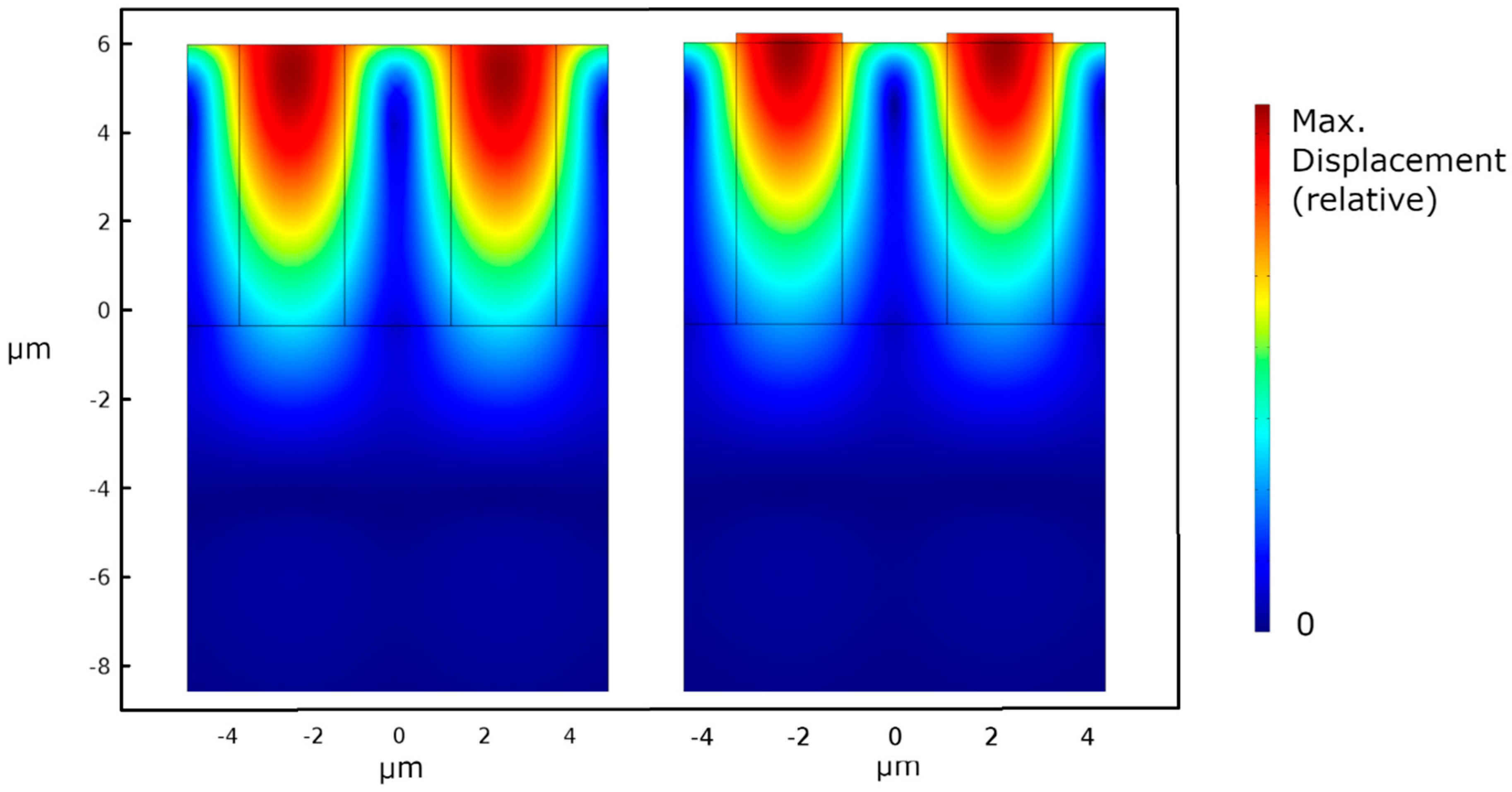
To analyze the impact of electrode mass loading on acoustic wave propagation, eigenfrequency FEM models were extended to include an electrode layer. To replicate real contacts while simplifying the simulation, a substitute electrode model, instead of the actual four-layer metal stack, was used: a single gold layer of greater thickness than that in fabricated samples. Gold was chosen because it is the first and thickest layer in the real structure. The equivalent gold thickness (by weight) was set to 230 nm. Material parameters for gold were taken from the literature [23]. The same 2D periodic unit cell formulation, material assignments (piezoelectric GaN; linear-elastic sapphire), and boundary conditions as those in previous simulations were retained. Simulations were performed for GaN thicknesses of 2 μm and 6 μm and for the Rayleigh and Sezawa surface wave modes. Material constants for GaN and sapphire were identical to those used earlier (Table 2 and Table 3). Mesh refinement ensured convergence of resonance/antiresonance eigenfrequencies. Figure 12 compares the simulated displacement/strain fields with and without the Au layer, highlighting mass-loading effects.
The displacement/strain field maps show that Au loading does not significantly alter the depth profile of the modal fields; the Rayleigh maxima remain near the free surface, and Sezawa maxima remain near the GaN–sapphire interface. Introducing the 230 nm Au layer produced the expected downshift of resonance frequency and phase velocity for both Rayleigh and Sezawa modes. The effect was stronger at smaller KH (thinner GaN layer), consistent with classical thin-film mass loading theory [19]. For the 2 μm GaN (Rayleigh mode), the resonance shifted from 521.9466 MHz (no electrodes) to 478.0186 MHz (with Au), i.e., Δf = 43.928 MHz and ΔVp = 395.352 ms−1. For the 6 μm GaN (Rayleigh), the frequency shift was 25.5765 MHz (velocity reduction 230.189 ms−1), while for the 6 μm GaN (Sezawa) the shift was 13.9982 MHz (velocity reduction 125.984 ms−1).

3.4. Energy Confinement Analysis

Figure 13 presents the total strain profile for the Rayleigh and Sezawa modes for GaN layers of 6 μm and 2 μm thicknesses based on results of the previous FEM simulation. The profile was calculated along the perpendicular line going through the center of the electrode.
The analysis revealed significant differences in wave propagation between the Rayleigh and Sezawa modes. For the Sezawa mode, maximum strain occurred near the interface, whereas for the Rayleigh mode, it was near the surface and decreased monotonically with depth. Comparing Rayleigh waves for 6 μm and 2 μm layers showed similar penetration depths into the sapphire substrate, but the maximum strain amplitude was higher for the 2 μm layer. This resulted from a similar electromechanical coupling coefficient but a smaller active piezoelectric volume, leading to larger deformations. To compare the Rayleigh and Sezawa modes, the energy confinement coefficient (n) was calculated, representing the fraction of total wave energy confined within the active piezoelectric layer versus that propagating into the sapphire substrate. Wave energy is proportional to the square of material strain [19], and integrating energy density along the strain profile determines the energy distribution across layers. The ratio of energy in GaN to total wave energy defines the energy confinement coefficient. Table 5 presents maximum strain values (at 1 V open circuit electrode excitation) and energy confinement coefficients for each mode.
Analysis showed that for Rayleigh waves the energy confinement coefficient n was equal to 60.2% for the 2 μm layer and 96.6% for the 6 μm layer, which means that almost all wave energy for transducers with KH = 4.2 was located in the GaN layer. In contrast, for the Sezawa mode in the 6 μm layer. only 38.3% of the energy was located in the GaN layer.

4. Summary

The article presents an analysis of the propagation of acoustic waves in gallium nitride (GaN) layers deposited on sapphire substrates. Due to the unique piezoelectric properties of GaN and the high quality of the sapphire substrate, these systems are used in electroacoustic devices such as resonators, filters, and sensors. This study focused on the analysis of propagation modes of acoustic waves generated by interdigital transducers (IDTs) in different configurations, considering the impact of technological parameters on wave properties. Interdigital transducers (IDTs) in various geometric configurations were used to excite surface waves in GaN layers of different thicknesses (2, 4, and 6 μm). Measurements were conducted using the “on-wafer” method, with an Agilent N5230A network analyzer in the frequency range from 100 MHz to 6 GHz. The results of the analysis showed that the conditions for wave propagation in these structures are strongly dependent on the GaN layer thickness, the IDT configuration, and the quality of the GaN–sapphire interface. The study revealed the occurrence of various propagation modes, including Rayleigh, Sezawa, Love, and pseudo-bulk waves. To better understand the wave propagation mechanism and the influence of technological parameters on their properties, numerical simulations were performed using the finite element method (FEM) in the Comsol Multiphysics environment. The analysis of the dispersion characteristics of Rayleigh waves showed that their propagation velocity depends on the KH coefficient (the ratio of the GaN layer thickness to the wavelength). For thin GaN layers, these waves propagate with a velocity close to that of the sapphire substrate. However, reducing the thickness of the GaN layer affects the transmission levels, as a smaller amount of piezoelectrically active material results in a lower total energy of the propagating acoustic wave. Additionally, a thinner layer is more vulnerable to defects introduced by lattice mismatch during epitaxy process. An alternative to Rayleigh waves is Sezawa modes, which offer several advantages. Their higher propagation velocities enable higher operational frequencies of the transducers without the need to reduce the layer thickness. Another benefit of Sezawa modes arises from the fact that the maximum amplitudes of material deformation occur deeper within the structure compared to Rayleigh modes. As a result, Sezawa modes are less susceptible to environmental influences—for instance, they undergo lower attenuation when the interdigital transducer is immersed in a fluid. It was also demonstrated that the presence of defects at the GaN–sapphire interface can reduce the propagation velocity and deteriorate the quality parameters of the transducers. The obtained results provide crucial insights for optimizing the technological processes involved in producing GaN layers on sapphire substrates, which is essential for enhancing the performance of devices that utilize acoustic waves. Relationships between GaN layer thickness, acoustic wavelength, and interface quality have been identified and should be carefully considered in the design of future electroacoustic systems. The conducted research and the results obtained can have practical applications in the design of modern sensors using surface waves, RF filters, and high-frequency resonators, which play a key role in telecommunications, navigation, and medical systems. In addition, recent advances in microfluidics [24] have highlighted the potential of another GaN, SAW transducers, on sapphire substrates application due to their capability to excite various propagation modes with well-defined characteristics. Additionally, GaN-based SAW transducers and GaN-based light sources could be integrated with microfluidic platforms, thereby opening entirely new application domains.

Author Contributions

Conceptualization, B.K.P., B.P. and A.D.; Methodology, B.P. and A.D.; Software, B.K.P.; Validation, B.K.P. and B.P.; Formal analysis, B.K.P.; Investigation, B.K.P. and B.P.; Resources, B.P. and A.D.; Writing—original draft, B.K.P.; Writing—review & editing, B.K.P. and A.D.; Supervision, A.D.; Project administration, A.D. All authors have read and agreed to the published version of the manuscript.

Funding

The research was co-financed by the subsidy of the Wroclaw University of Science and Technology. The research was accomplished through the product indicators and result indicators achieved under the projects of the National Center for Research and Development: Project LEADER No. 027/533/L-5/13/NCBR/2014 and Project TECHMATSTRATEG No. 1/346922/4/NCBR/2017.

Data Availability Statement

Data are contained within the article.

Conflicts of Interest

The authors declare no conflict of interest.

References

  1. Wośko, M. Optimisation of LT-GaN nucleation layer growth conditions for the improvement of electrical and optical parameters of GaN layers. Opt. Appl. 2019, 49, 167–176. [Google Scholar] [CrossRef]
  2. Macherzynski, W.; Gryglewicz, J.; Stafiniak, A.; Prazmowska, J.; Paszkiewicz, R. Formation process and properties of ohmic contacts containing molybdenum to AlGaN/GaN heterostructures. Adv. Electr. Electron. Eng. 2016, 14, 83–88. [Google Scholar] [CrossRef]
  3. Macherzyński, W.; Stafiniak, A.; Paszkiewicz, B.; Gryglewicz, J.; Paszkiewicz, R. Microanalysis of the Ti/Al and Ti/Al/Mo/Au ohmic contacts metallization to AlGaN/GaN heterostructures. Phys. Status Solidi (A) Appl. Mater. Sci. 2016, 213, 1145–1149. [Google Scholar] [CrossRef]
  4. COMSOL AB. COMSOL Multiphysics®, Version 4.3; COMSOL AB: Stockholm, Sweden, 2025.
  5. Rais-Zadeh, M.; Gokhale, V.J.; Ansari, A.; Faucher, M.; Theron, D.; Cordier, Y.; Buchaillot, L. Gallium nitride as an electromechanical material. J. Microelectromechan. Syst. 2014, 23, 1252–1271. [Google Scholar] [CrossRef]
  6. Bernstein, B.T. Elastic constants of synthetic sapphire at 27 °C. J. Appl. Phys. 1963, 34, 169–172. [Google Scholar] [CrossRef]
  7. Bernardini, F.; Fiorentini, V. First-principles calculation of the piezoelectric tensor d of III–V nitrides. Appl. Phys. Lett. 2002, 80, 4145–4147. [Google Scholar] [CrossRef]
  8. Almirall, A.; Oliveri, S.; Daniau, W.; Margueron, S.; Baron, T.; Boulet, P.; Ballandras, S.; Chamaly, S.; Bartasyte, A. High-frequency surface acoustic wave devices based on epitaxial Z-LiNbO3 layers on sapphire. Appl. Phys. Lett. 2019, 114, 162905. [Google Scholar] [CrossRef]
  9. Pedrós, J.; Calle, F.; Grajal, J.; Riobóo, R.J.J.; Takagaki, Y.; Ploog, K.H.; Bougrioua, Z. Anisotropy-induced polarization mixture of surface acoustic waves in GaN/c-sapphire heterostructures. Phys. Rev. B 2005, 72, 75306. [Google Scholar] [CrossRef]
  10. Mueller, A.; Giangu, I.; Stavrinidis, A.; Stefanescu, A.; Stavrinidis, G.; Dinescu, A.; Konstantinidis, G. Sezawa propagation mode in GaN on Si surface acoustic wave type temperature sensor structures operating at GHz frequencies. IEEE Electron. Device Lett. 2015, 36, 1299–1302. [Google Scholar] [CrossRef]
  11. Fu, Y.Q.; Luo, J.; Nguyen, N.; Walton, A.; Flewitt, A.; Zu, X.; Li, Y.; McHale, G.; Matthews, A.; Iborra, E.; et al. Advances in piezoelectric thin films for acoustic biosensors, acoustofluidics and lab-on-chip applications. Prog. Mater. Sci. 2017, 89, 31–91. [Google Scholar] [CrossRef]
  12. Farnell, G.W.; Adler, E.L. Elastic wave propagation in thin layers. Phys. Acoust. 2012, 9, 35–127. [Google Scholar] [CrossRef]
  13. Jaafar, M.M.; Wee, M.F.M.R.; Nguyen, H.-T.; Hieu, L.T.; Rai, R.; Sahoo, A.K.; Dee, C.F.; Chang, E.Y.; Majlis, B.Y.; Tee, C.A.T. Surface Acoustic Wave Propagation of GaN/Sapphire Integrated with a Gold Guiding Layer. Sensors 2023, 23, 2464. [Google Scholar] [CrossRef] [PubMed]
  14. Jaafar, M.M.; Mohd Razip Wee, M.F.; Dee, C.F.; Chang, E.Y.; Majlis, B.Y. Sezawa Guided Mode on Periodic Grooves of GaN/Sapphire Substrate. Electron. Mater. Lett. 2022, 18, 415–421. [Google Scholar] [CrossRef]
  15. Caliendo, C.; Benetti, M.; Cannatà, D.; Laidoudi, F.; Petrone, G. Experimental and Theoretical Analysis of Rayleigh and Leaky-Sezawa Waves Propagating in ZnO/Fused Silica Substrates. Micromachines 2024, 15, 974. [Google Scholar] [CrossRef] [PubMed]
  16. Gaso Rocha, M.I.; Jimenez, Y.; Laurent, F.A.; Arnau, A. Love Wave Biosensors: A Review. In State of the Art in Biosensors—General Aspects; IntechOpen: London, UK, 2013. [Google Scholar] [CrossRef]
  17. Caliendo, C.; Sait, S.; Boubenider, F. Love-mode MEMS devices for sensing applications in liquids. Micromachines 2016, 7, 15. [Google Scholar] [CrossRef]
  18. Liu, B.; Chen, X.; Cai, H.; Ali, M.M.; Tian, X.; Tao, L.; Yang, Y.; Ren, T. Surface acoustic wave devices for sensor applications. J. Semicond. 2016, 37, 021001. [Google Scholar] [CrossRef]
  19. Auld, B.A.; Green, R.E. Acoustic Fields and Waves in Solids: Two Volumes. Phys. Today 1974, 27, 63–64. [Google Scholar] [CrossRef]
  20. Paszkiewicz, B.K.; Gierz, L. Pseudo-bulk SAW transducers fabricated in GaN epitaxial layers grown on sapphire substrate. In Journal of Physics: Conference Series; IOP Publishing: Bristol, England, 2021. [Google Scholar] [CrossRef]
  21. Bu, G.; Ciplys, D.; Shur, M.; Schowalter, L.J.; Schujman, S.; Gaska, R. Electromechanical coupling coefficient for surface acoustic waves in single-crystal bulk aluminum nitride. Appl. Phys. Lett. 2004, 84, 4611–4613. [Google Scholar] [CrossRef]
  22. Woods, R.C.; Boroumand, F.A. Comments on ‘Epitaxially grown GaN thin-film SAW filter with high velocity and low insertion loss’. IEEE Trans. Electron. Devices 2006, 53, 173–176. [Google Scholar] [CrossRef]
  23. Neighbours, J.R.; Alers, G.A. “Elastic constants of silver and gold. Phys. Rev. 1958, 111, 707–712. [Google Scholar] [CrossRef]
  24. Liu, X.; Chen, X.; Yang, Z.; Xia, H.; Zhang, C.; Wei, X. Surface acoustic wave based microfluidic devices for biological applications. Sensors Diagn. 2023, 2, 507–528. [Google Scholar] [CrossRef]
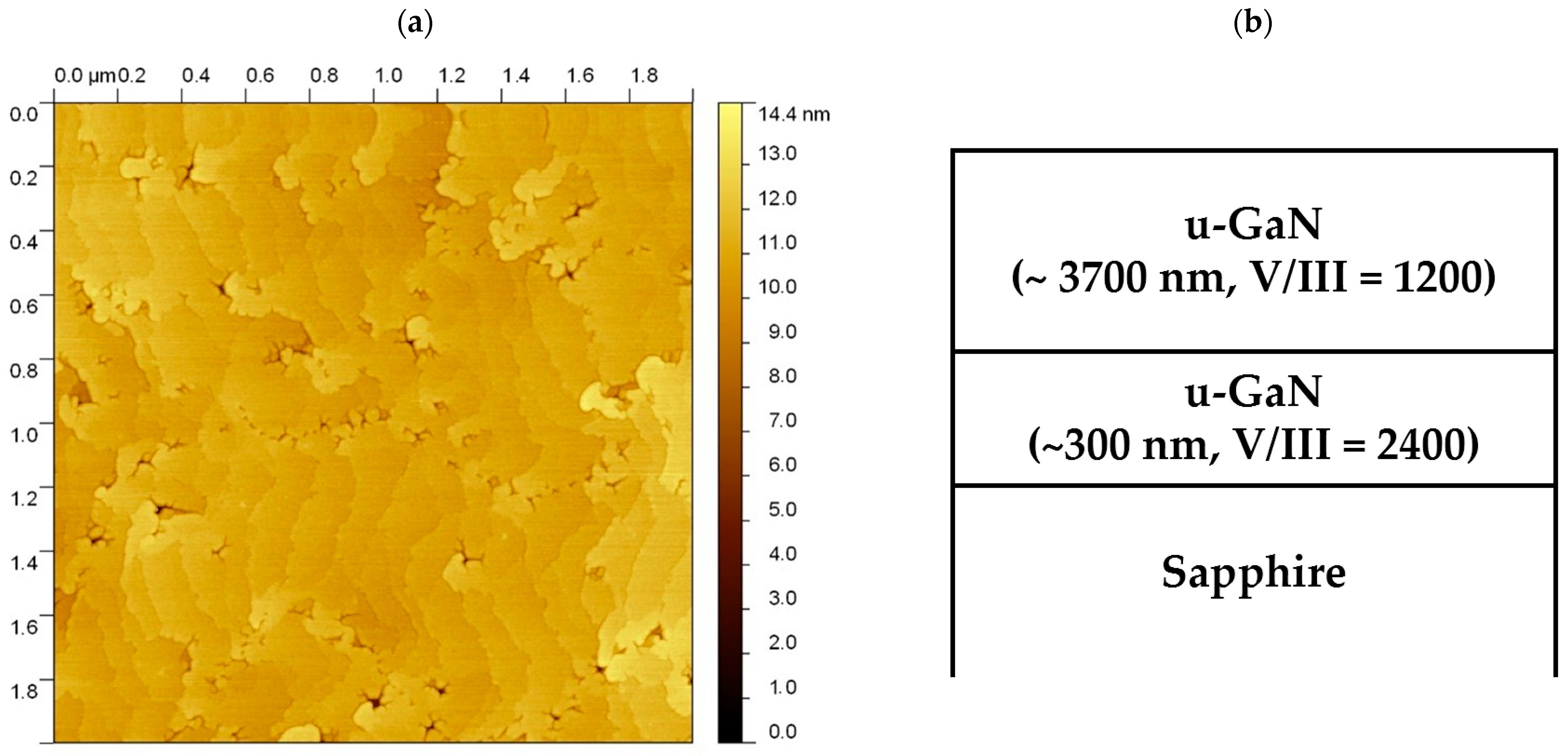
Figure 1. (a) an AFM image of GaN/sapphire layer [1]. (b) Schematic of the applied epitaxial layer (thickness: 4 μm). V/III symbol denotes ratio of flow of TMGa and NH3.
Electronics 14 04146 g001
Figure 2. (a) View of one side of interdigital transducer with visible contact pads for on-wafer measurements. (b) Enlarged view showing an interdigital transducer of type 10. (c) Enlarged view showing an interdigital transducer of type 1100.
Electronics 14 04146 g002
Figure 3. Characteristic of the transducer reflectance (λ = 18 μm, N = 24) fabricated on a 2 μm GaN layer and directly on sapphire substrate.
Electronics 14 04146 g003
Figure 4. Characteristics of the transducer transmittance (λ = 18 μm, N = 24) fabricated on a 2 μm GaN layer and directly on sapphire substrate.
Electronics 14 04146 g004
Figure 5. Dispersion characteristics of GaN layer on sapphire.
Electronics 14 04146 g005
Figure 6. Deformation field (relative total strain magnitude, right scale) of the Rayleigh wave in the GaN/sapphire system (finger spacing λ = 9 μm) for two GaN layer thicknesses 6 μm (left: KH = 4.2, 435 MHz) and 2 μm (right: KH = 1.4, 522 MHz).
Electronics 14 04146 g006
Figure 7. Strain field of Rayleigh (left) and Sezawa (right) wave in GaN/sapphire system (finger spacing λ = 9 μm, GaN thickness d = 6 μm, KH = 4.1, resonance frequency 435 MHz—Rayleigh, 655 MHz—Sezawa).
Electronics 14 04146 g007
Figure 8. Frequency response of interdigital transducers (IDTs) with λ = 9 μm and N = 48 on a 4 μm GaN layer. The Sezawa mode can be observed at a frequency of 662.39 MHz. (R—Rayleigh; S—Sezawa; PB—pseudo-bulk; 3R—3rd Rayleigh harmonics).
Electronics 14 04146 g008
Figure 9. Characteristic of the interdigital transducer with λ = 18 μm and N = 24 made on a 2 μm GaN layer.
Electronics 14 04146 g009
Figure 10. Frequency characteristics of the S-parameter modules for a pair of transducers with a λ = 18 μm mode made on a 4 μm thick GaN layer, where Love modes occur.
Electronics 14 04146 g010
Figure 11. Deformation field (relative total strain magnitude, right scale) of the Sezawa wave in the GaN/sapphire system (finger spacing λ = 9 μm, GaN thickness H = 6 μm) for resonance (left: 655.3419 MHz) and antiresonance (right: 655.4982 MHz).
Electronics 14 04146 g011
Figure 12. Deformation field (relative total strain magnitude, right scale) of the Rayleigh wave in the GaN/sapphire system (finger spacing λ = 9 μm, GaN thickness H = 6 μm) without electrodes (left, 435.3 MHz) and with electrodes (right, 409.7 MHz).
Electronics 14 04146 g012
Figure 13. Total strain as a function of depth (X = 0 denotes the GaN–sapphire interface).
Electronics 14 04146 g013
Table 1. List of transducer configurations used in this paper.
Configurationλ [μm]Repetition Number
011824
011812
01948
00111824
Table 2. Material data for GaN used in simulations.
ParameterTensor ElementValue
Stiffness, cij, [GPa]c11390
c33398
c44105
c12145
c13106
Piezoelectric coefficient, eij, [Cm−2]e16−0.3
e31−0.289
e330.464
Relative permittivityϵr8.9
Table 3. Material data for sapphire used in simulations.
ParameterTensor ElementValue
Stiffness, cij, [GPa]c11490
c33492
c44146
c13114
c14−23
Relative permittivityϵr9.4
Table 4. k2 values for different modes and layer thicknesses.
ModeKHk2
Rayliegh1.40.096%
Rayliegh4.20.098%
Sezawa4.20.048%
Table 5. Maximum displacement and energy confinement coefficient n for different modes and GaN layer depths.
ModeKHMax. Displacement [nm]n [%]
Rayliegh1.47.660.2
Rayliegh4.22.196.6
Sezawa4.23.238.3
Disclaimer/Publisher’s Note: The statements, opinions and data contained in all publications are solely those of the individual author(s) and contributor(s) and not of MDPI and/or the editor(s). MDPI and/or the editor(s) disclaim responsibility for any injury to people or property resulting from any ideas, methods, instructions or products referred to in the content.