Abstract
Forest fire monitoring is of great significance for ecological protection and public safety. This study proposes a monitoring technology based on LoRa-Mesh (Long Range-Mesh) wireless communication, integrating temperature and humidity sensing, image acquisition, fire identification, data transmission, and energy-saving optimization. To address the limitations of traditional LoRa networks in flexibility and energy consumption, a Layered Dynamic Synchronization Energy-saving (LDSE) protocol is designed. By constructing a hierarchical network, employing implicit route exploration, multi-channel and multi-path communication, and time synchronization optimization, the protocol significantly reduces packet loss rate and system energy consumption. Experimental results demonstrate that the LDSE protocol outperforms the traditional Ad hoc On-Demand Distance Vector Routing Protocol (AODV) in terms of packet loss rate, energy consumption, and latency. Additionally, the proposed energy-saving algorithm significantly reduces system power consumption, with the node sleep-relay mode exhibiting optimal energy efficiency. Experimental verification confirms that the system achieves high reliability, low power consumption, and efficient data transmission, providing an effective IoT solution for forest fire prevention.
1. Introduction
Globally, the increasing frequency and severity of forest fires have significantly impacted biodiversity, vegetation, and ecological environments [1]. Additionally, they are a major source of carbon dioxide and other greenhouse gas emissions [2]. Relevant studies indicate that the global surface temperature is expected to rise by at least 1.5 °C in the coming decades [3]. Furthermore, forest fires release large amounts of PM2.5, and exposure to such airborne particles may lead to various health issues, including cardiovascular diseases, respiratory illnesses, and neonatal disorders [2].
Since its emergence in 2013, LPWAN [4,5] technology has achieved rapid development. Market analysis shows that the global shipment volume of LPWAN chipsets had exceeded 100 million units in 2018. In the next five years, this market is expected to continue to expand at a compound annual growth rate (CAGR) of 109% [6], and the scale of related equipment is expected to reach 1 billion units by 2025. The advantage of LPWAN lies in its ability to ensure the long-term operation of devices over a wide area, while maintaining stable communication even in remote regions.There are many types of LPWAN technologies, such as NB-IoT [7], LTE-M [8], Sigfox [9,10], LoRa [11,12,13], etc. Among them, LoRa has become one of the most popular LPWAN technologies due to its low power consumption and long lifespan.
Currently, various LPWAN technologies have been successfully applied in agriculture, animal husbandry, and healthcare. In agriculture, Ruipeng Tang’s team [14] designed the EMP-ZBR algorithm by improving the Zigbee protocol, effectively alleviating network congestion and significantly enhancing data monitoring performance in agricultural greenhouse wireless sensor networks. For intelligent transportation, Arunkumar Palaniappan [15] developed a smart lane control system based on ZigBee IoT technology, providing innovative solutions for traffic management. Additionally, Kamal Ghoumid’s [16] research team optimized medical monitoring systems in smart cities using NB-IoT technology, achieving significant improvements in average message delivery time and offering reliable technical support for remote medical monitoring. These research outcomes fully demonstrate the application value and development potential of LPWAN technologies across different fields.
In contrast, LoRa technology features long transmission distances and low power consumption, making it particularly suitable for large-scale monitoring.Its broader network coverage reduces the number of nodes required for deployment, positioning LoRa as a more appropriate choice for environmental monitoring.
LoRa networks adopt the LoRaWAN [17] specification. Unlike proprietary physical layer solutions, LoRaWAN is designed as an open standard network protocol. However, LoRaWAN employs a star topology [18] where nodes communicate directly with gateways. This single-hop communication approach lacks flexibility and robustness, presenting a significant limitation in expansive areas. LoRa-Mesh has been identified as a potential solution to overcome these constraints.
LoRa-Mesh has been widely applied in environmental monitoring. For instance, Yu Chen [19] implemented a LoRa-Mesh network for intelligent weather detection along railway tracks. T. Lindquist et al. [20] employed LoRa-Mesh networks for lake health data collection, achieving real-time monitoring capabilities. Dixin Wu et al. [21] designed a large-scale environmental monitoring system using LoRa-Mesh networks, demonstrating >90% packet reception rates in field tests.
Recent years have witnessed significant breakthroughs in IoT-based intelligent forest fire monitoring systems. The research team led by Lehnert A [22] innovatively integrated edge computing with explainable AI technology to develop a novel smoke detection system incorporating low-power gas sensors and 5G communication, which achieved remarkable improvements in both fire recognition accuracy and real-time performance. Meanwhile, Basu M.T.’s team [23] created a NodeMCU-based intelligent fire monitoring system that combines multi-source sensor data (temperature, smoke, etc.) with Arduino-controlled buzzer alarms, establishing a comprehensive early warning solution.
In the field of machine learning applications, researchers including Giacomo Peruzzi [24] made groundbreaking progress. Their two embedded machine learning algorithms demonstrated exceptional fire detection performance on low-power devices, achieving outstanding evaluation metrics: 96.15% accuracy, 92.3% precision, 100% recall, and 96% F1-score. The system employs LoRaWAN protocol for reliable signal transmission, and its prototype VSU device has been recognized by the industry as an innovative solution combining embedded machine learning algorithms with advanced communication protocols.
Furthermore, scholars such as Roberto Vega-Rodríguez [25] and Dharmesh M [26] have made significant contributions to communication networking technologies. By optimizing LoRa networking combined with dynamic risk assessment models, they achieved not only precise fire detection but also real-time monitoring of multiple environmental risk indicators, providing intelligent support for forest fire prevention decisions. These technological innovations have collectively driven the rapid development of intelligent, networked forest fire monitoring systems, substantially enhancing fire prevention capabilities.
Due to the remote and expansive nature of forest environments, LoRa technology has emerged as one of the most efficient solutions for forest fire monitoring, offering advantages of long-range communication, low energy consumption, minimal maintenance requirements, and cost-effectiveness. However, while LoRa technology excels in long-distance communication, existing LoRa networks suffer from energy imbalance issues as each node maintains only a single fixed path to the gateway. To address this challenge, our study proposes an innovative Layered Dynamic Synchronization Energy-efficient (LDSE) protocol.
Particularly in forest monitoring applications where nodes are typically deployed long-term in harsh, remote environments with difficult maintenance conditions, energy management becomes crucial for system reliability and operational lifespan. This paper presents a dynamic energy-saving control algorithm based on node sleep-relay mechanisms, which optimizes system energy consumption through intelligent scheduling of node sleep-wake cycles, thereby significantly reducing overall energy usage and extending network lifetime.
2. Methodology
2.1. LoRa
LoRa (Long Range) is a wireless communication technology specifically designed for long-range, low-power data transmission. To initiate LoRa transmission, several key parameters need to be set, including the spreading factor (SF), bandwidth (BW), and coding rate (CR). In LoRa transmission, the configuration of these key parameters directly affects the data rate and transmission time. The symbol rate is determined by the bandwidth, while the relationship between the bit rate and these parameters is given by the following formula [Semtech AN1200.22]:
- (1)
- where denotes the bit rate.The airtime of a LoRa packet, which is the time required to transmit the packet over the air, can be calculated based on the bit rate and the packet structure.The formula is as follows:
For a simplified representation often used in system-level analysis, the airtime can be approximated as:
- (2)
- Among them, and represent the payload length in bytes and preamble length in symbols, respectively. The constant 4.25 accounts for the synchronization word and other fixed overheads in the packet preamble.
Classification of CNN Models
In the LoRa-Mesh based forest fire monitoring system, this study evaluates the performance of mainstream CNN architectures including VGG16, MobileNetV3, SqueezeNet, and EfficientNet. The forest fire dataset consists of 5000 annotated fire images from the public fire database and field-collected forest scene images covering various seasons, time periods, and weather conditions.The data is split into 4000 training images (80%) and 1000 test images (20%). Preprocessing includes resizing images to 160 × 160 pixels, converting to RGB format, and pixel value normalization.Training data augmentation involves random exposure adjustment (±20%) and 4-image mosaic blending. We kept the test set unchanged to ensure reliable evaluation. Table 1 presents the comparative analysis of different CNN models’ complexity and performance using this preprocessing pipeline.

Table 1.
Trade-off between Model Complexity and Performance.
Among:
To ensure accuracy, the computational complexity and number of parameters in the model must be minimized as much as possible, given the limited resources of microcontrollers. This reduces inference time and power consumption. In summary, MobileNetV3 is an ideal choice for a LoRa-based forest fire detection system, as it offers fast inference speed and high accuracy in low-bandwidth, low-power environments. Our framework for Forest fire monitoring is overviewed in Figure 1.
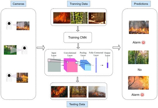
Figure 1.
Energy-saving deep CNN forest fire identification in the Internet of Things environment.
2.2. Layered Dynamic Synchronous Energy-Efficient Protocol (LDSE)
LDSE: In many application scenarios, a large number of End-device Nodes (ENs) are deployed in the detection environment, but typically only one gateway is present. Since energy ENs are often not evenly distributed horizontally, the distances from the energy ENs to the gateway can vary significantly and are unpredictable. To collect data from all energy ENs in the shortest time possible with minimal energy consumption, the LDSE protocol has been designed. The design of the LDSE protocol consists of the following four steps:
- Concurrent Transmission (CT) Layering: All energy ENs are quickly assigned to a specific network layer.
- Implicit Route Exploration: The protocol identifies its routing paths.
- Multi-channel Multi-path Communication: This step balances the load across multiple channels and paths.
- Time Synchronization: ensuring that all ENs operate on a synchronized time frame.
2.2.1. CT Layering
Network layer formation involves assigning all ENs to specific network layers. Each network layer is independent of each other and can communicate with each other. The smaller the number of layers of EN, the closer it is to the gateway; otherwise, the farther it is from the gateway. Each EN is assigned to a network layer using an “initialization message” message type. The initialization message contains two fields: a 1-byte command identifier (CID, fixed at 0x01) and a 1-byte network layer index (Layer, initially set to 0xFF).
- (1)
- CommandID (CID): An identifier that controls initialization.
- (2)
- Layer: Network layer index of ENs.
In the initial phase, the gateway’s initial layer is set to “00”, and ENs are initialized with a layer value of “0xff”.The gateway broadcasts an initialization message “0100”, which is received by the ENs that are one hop away.These adjacent ENs update their layer index to “0x01” (initial layer index + 1), update the initialization message to “0101” and broadcast the updated message.
This process repeats, with each EN receiving and rebroadcasting the updated initialization message while updating its layer index. This continues until all ENs have determined their respective layers. ENs with smaller layer indices are closer to the gateway, while those with larger layer indices are farther from the gateway. Through this process, all ENs are assigned to their respective layers. Figure 2 illustrates the final layer allocation results.
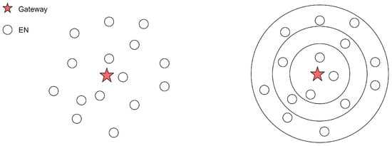
Figure 2.
Hierarchical hierarchy diagram.
2.2.2. Implicit Route Exploration (IRE)
After the hierarchical allocation process is completed, paths need to be assigned to each ENs. The ENs transmit data to the gateway through these paths.An efficient path allocation method is crucial for receiving and forwarding data.The format of the initial exploration message is set as shown in Table 2.

Table 2.
Format of initializing message2.
- (1)
- CommandID (CID): an identifier that controls initialization.The length of commandid is set to 1 byte.
- (2)
- Layer: indicates the network layer index of the ENs. Set the length to 1 byte.
- (3)
- SenderID (SID): indicates the identifier of the sender. The length is set to 2 bytes.
- (4)
- ReceiverID (RID): identifier of the receiver. Length is set to 2 bytes.
- (5)
- Message: The data that the gateway needs to upload.
In the process of route discovery, there are two main methods for a child EN to locate its parent EN: (1) Active route discovery (2) Passive route discovery. When a given child EN wants to send a message to a higher-level EN but does not know its parent EN, the child EN will broadcast a discovery message. All parent ENs can receive this message and forward it to the next level. Once the message is successfully forwarded, all ENs, including the child EN, can detect the discovery message. By analyzing the “SenderID” and “Layer” information in the detected message, the child EN can determine its parent EN, allowing the message to be sent from the child EN to the parent EN and eventually reach the gateway. In addition to active route discovery, there is also passive route discovery. In this case, a sibling EN of the given child EN does not need to send a message itself; it can find its parent EN by listening to the discovery message sent by the child EN. The key difference between active and passive route discovery is that passive discovery does not require actively sending messages, but it cannot find all parent ENs in one go. Instead, it requires multiple message transmissions to gradually discover all parent ENs. In summary, the active and passive route discovery methods effectively complement each other in terms of overhead and efficiency. The primary advantage of active route discovery lies in its ability to enable the initiating child End Node (EN) to rapidly and simultaneously identify all its available parent ENs, facilitating direct path establishment. However, its drawback is the requirement to actively broadcast probe messages, which generates additional communication overhead.
In contrast, the strength of passive route discovery is that other child ENs can learn routes through eavesdropping without needing to transmit their own probe messages, significantly conserving individual node energy consumption and network bandwidth.Its main limitation is that path discovery relies on the behavior of neighboring nodes, introducing elements of randomness and delay, which may prevent the immediate establishment of an optimal path.
By integrating these two mechanisms, the LDSE protocol effectively controls the overall network overhead while enhancing the efficiency of route establishment.
As shown in the Figure 3, EN E attempts to locate its parent EN. EN E broadcasts a discovery message, which can be received and forwarded by ENs A and B. Sibling ENS C, D, F, and G listen to the message and analyze the information within the discovery message to locate their respective parent ENs. The process in which EN E searches for its route is called active route discovery, while the process through which sibling ENs C, D, F, and G discover their routes is referred to as passive route discovery.
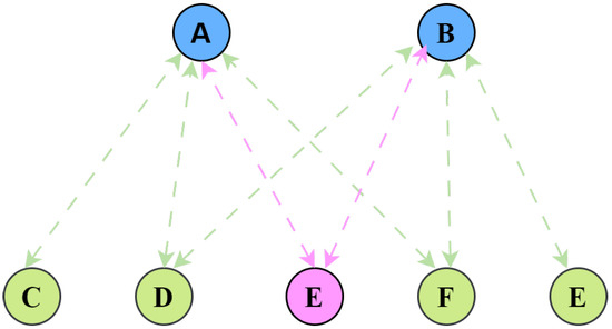
Figure 3.
IRE process diagram.
2.2.3. Multi-Channel Multi-Path Communication
In most cases, ENs transmitting on different channels can significantly reduce the likelihood of collisions. Multi-path transmission refers to having multiple paths from a specified EN to the gateway. When the EN has multiple parent ENs, it can arbitrarily choose one of them. Compared to single-path transmission (where there is only one path from the EN to the gateway), multi-path communication enables load balancing of network traffic. For example, during the next data transmission, the specified EN can select the parent EN with lower energy consumption from its multiple parent ENs to serve as the current parent EN.
Each EN is allocated two channels: (1) aprivate channel (Prc), (2) public channel (Puc). Every EN has its own Prc. Before transmitting data, the specified EN listens on a random channel and selects an appropriate unused Prc of a neighboring EN. Child ENs monitor the Puc before transmitting handshake messages. They only proceed when the channel is idle, otherwise delaying transmission to prevent collisions. The handshake message includes the identifier of the selected Prc When the parent EN receives the handshake message, it analyzes the load information of the Prc to determine that subsequent data transmissions will occur through that Prc. The parent EN then notifies the child EN via Puc, and the child EN receives the message. At this point, both the parent and child ENs are aware of the designated Prc, and all subsequent data transmission can take place over this private channel. The process of selecting Prc is illustrated in Figure 4.
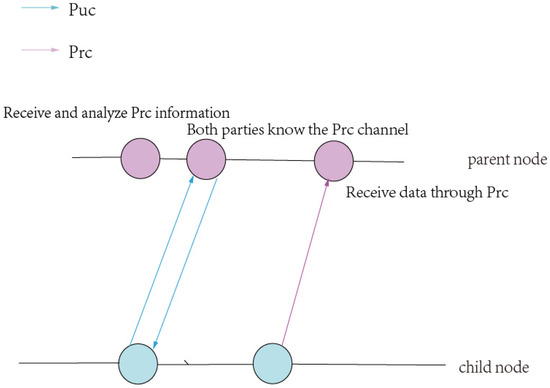
Figure 4.
Dynamic allocation process.
As shown in Figure 5, EN A selects Prc1 as its private channel for transmitting information to its parent EN. Before EN B can transmit data, it needs to listen on the channel. Since Prc1 is already in use, it cannot be selected as the private channel for another child EN. EN B must choose a different, unused private channel. This method prevents the “congestion” issue that occurs when multiple neighboring ENs select the same private channel, which would otherwise disrupt normal data transmission.
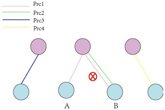
Figure 5.
Channel congestion.
2.2.4. Time Synchronization
Time synchronization is crucial for routing protocols, as the lack of synchronization may lead to data loss and network failures. Moreover, in the absence of an external time source for synchronization, microcontrollers often rely on crystal oscillators to track time. However, crystal oscillators are subject to drift over time. Therefore, to ensure stable network operation, periodic network-wide time synchronization is required.
In this study, the Flooding Time Synchronization Protocol (FTSP) is employed to achieve global time synchronization. The gateway serves as the time reference source and periodically broadcasts synchronization messages containing its own timestamp. Upon receiving the message, each EN records the reception timestamp and, based on the transmission timestamp in the message and the propagation delay, calculates the time difference with the gateway. Subsequently, the EN adjusts its local clock to achieve synchronization.
As shown in Figure 6, the implementation process consists of four steps:
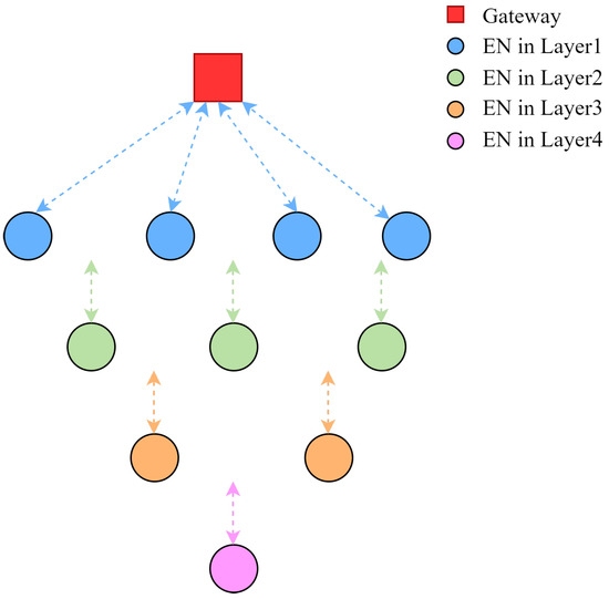
Figure 6.
Time Synchronization.
- (1)
- Gateway Broadcast: The gateway periodically transmits synchronization messages containing an accurate timestamp representing the moment of transmission.
- (2)
- Node Forwarding: Upon receiving the synchronization message, a node updates the relevant information in the message and forwards it to its child ENs, ensuring the message propagates throughout the network via flooding.
- (3)
- Timestamp Recording: When a node receives the synchronization message, it records the precise reception timestamp. By comparing this timestamp with the transmission timestamp in the message and estimating the propagation delay, the node calculates the time deviation from the root node (gateway).
- (4)
- Clock Adjustment: Based on the computed time deviation, the node adjusts its local clock to achieve synchronization with the gateway.
3. Forest Fire Identification System Based on LoRa-Mesh Wireless Network
This paper proposes an intelligent forest fire monitoring system based on a LoRa-Mesh wireless communication network. The system adopts a distributed architecture with clearly defined functional components:end-node devices integrate environmental sensors (SHT31 temperature and humidity sensor, Sensirion, Stäfa, Switzerland) and camera modules (OV5640, OmniVision Technologies Inc., Santa Clara, CA, USA), coordinated by LoRa communication modules (SX1262, Semtech Corporation, Camarillo, CA, USA); the gateway device (RAK7258, RAKwireless Technology, Shenzhen, China) is responsible for data aggregation, preliminary threshold analysis, and system coordination management;the deep learning-based fire recognition (MobileNetV3) is deployed at the gateway level for initial processing, while complex analysis functions reside at the central server. All components operate collaboratively under the unified scheduling of the innovative Layered Dynamic Synchronization Energy-saving (LDSE) protocol. The system categorizes nodes into two functional types:data collection nodes and relay forwarding nodes. To optimize communication reliability and reduce energy consumption, a Hierarchical Mesh Topology is adopted. Temperature and humidity sensor nodes are deployed hierarchically, collecting environmental data every 5 min and transmitting it to relay nodes via LoRa wireless communication. Relay nodes perform both local data collection and aggregation of information from child nodes, forwarding data to the gateway through multi-hop routing.
The gateway continuously analyzes temperature and humidity data from all nodes. When detecting an area meeting the “30–30” threshold condition [27] (validated by research as highly sensitive for early fire detection, moreover international applications including Canada’s Fire Weather Index (FWI) system identifying 30 °C temperature and 30% relative humidity as critical thresholds for Fine Fuel Moisture Code (FFMC), and the NFPA standards recommending this threshold for fire warning in arid regions), it activates the camera wake-up mechanism in that area. Awakened cameras employ block-based compressed transmission technology, prioritizing upload of high-confidence region image data. The gateway’s fire detection model performs real-time image analysis with multi-frame verification to improve accuracy. Upon fire confirmation, the system immediately triggers audible/visual alarms and transmits fire location, image evidence, and environmental parameters to the central server via the gateway. Figure 7 shows the system architecture.
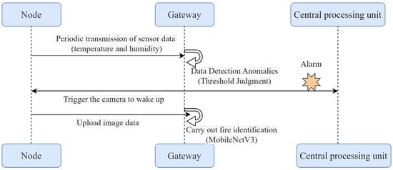
Figure 7.
System architecture diagram.
4. Energy-Saving Strategy
Dynamic Energy-Saving Control Algorithm with Node Sleep Relay
The energy consumption of node directly determines its lifespan, reliability, and stability. Most nodes are deployed in harsh natural environments where replacing batteries is inconvenient. In this study, the outermost nodes primarily undertake data collection functions, while the inner nodes are responsible for both data collection and relay functions. Therefore, it is particularly important to improve the energy utilization rate of inner nodes, reduce their energy consumption, and extend their service life. The main steps of the Dynamic Energy-Saving Control Algorithm with Node Sleep Relay are as follows:
- (1)
- Load Monitoring and Sleep Decision:Each node periodically reports its load status (such as data collection frequency and data transmission volume) to the base station. During periods of low fire risk (such as nighttime or the rainy season), the gateway can command some nodes to enter sleep mode to reduce energy consumption.
- (2)
- Coverage Compensation: When some nodes enter sleep mode, the gateway can adjust the working modes of other nodes or find alternative transmission routes.
- (3)
- Dynamic Wake-Up: When a node detects a fire risk, the gateway immediately notifies nearby nodes to ensure real-time data transmission.
The formula for calculating the total system power consumption is:
where:
- is the active mode power consumption
- is the sleep mode power consumption
- is the state switching power consumption
The simulation results are shown in the Figure 8, Figure 9 and Figure 10 below after adopting the node sleep relay dynamic control algorithm node.
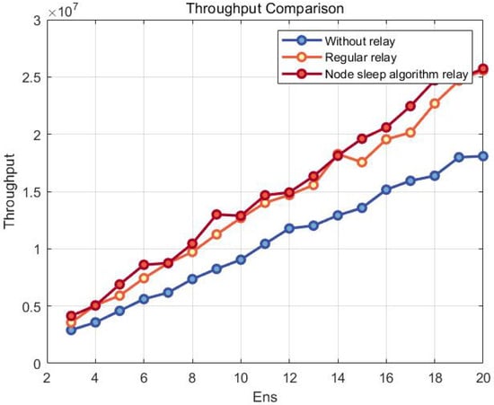
Figure 8.
Throughput Comparison.
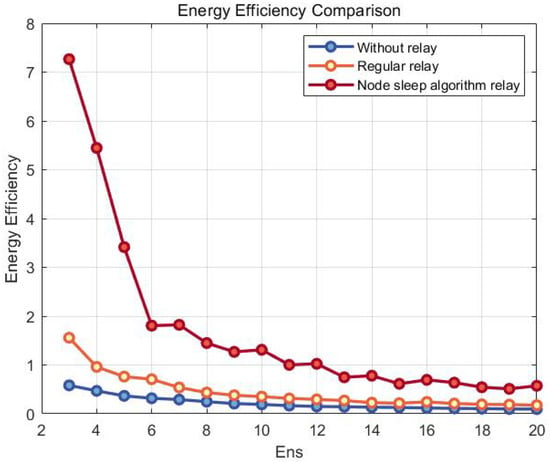
Figure 9.
Energy Efficiency Comparison.
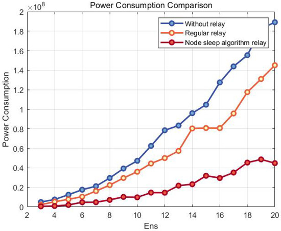
Figure 10.
Power Consumption Comparison.
The simulation results show that, in terms of system throughput, the performance ranking of different relay strategies is as follows: relay with the node sleep algorithm > ordinary relay > no relay. This indicates that the node sleep algorithm significantly improves throughput in relay mode, demonstrating the best performance.
From a theoretical analysis perspective, the theoretical system throughput values of the ordinary relay algorithm and the node sleep relay algorithm are similar. However, in practical deployment, due to mutual interference between the gateway and nodes, the node sleep algorithm effectively reduces signal interference in adjacent areas by dynamically shutting down inactive nodes, resulting in slightly higher actual throughput compared to the ordinary relay algorithm.
In terms of energy efficiency, the ranking of the three strategies is as follows: relay with the node sleep algorithm < ordinary relay < no relay. Experimental data show that the node sleep algorithm not only optimizes throughput but also significantly reduces system energy consumption, further enhancing the overall energy efficiency of the network. This characteristic makes it more practical in resource-constrained IoT environments.
5. Experimental
5.1. Time Synchronization
In the Flooding Time Synchronization Protocol (FTSP) based tests, we evaluated scenarios both with and without the time synchronization module.
As shown in Figure 11, the simulation results demonstrate that in the unsynchronized system, the error accumulates continuously over time, reaching 0.045 by 1000 s. In contrast, the synchronized system exhibits only a gradual error increase to 0.01, with significantly slower growth. Furthermore, the synchronization module reduces cumulative error by 16.7% within the 1000-s period, effectively validating its performance enhancement capability.
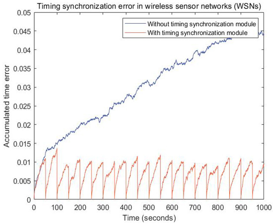
Figure 11.
Timing Synchronization Error Comparison.
5.2. Simulation Experiment
In the simulation experiment phase, this study employs the professional LoRa network simulation platform LoRaSim for performance evaluation. The experimental scenario simulates a real forest monitoring environment, where ENs are deployed in a hierarchical structure across the field area, with outer-layer nodes outnumbering inner-layer nodes. This node distribution density corresponds to typical forest fire monitoring scenarios. The detailed simulation parameter settings are specified in Table 3, with these configurations thoroughly accounting for both communication characteristics and environmental factors in practical deployments.

Table 3.
Simulation Parameters.
- (1)
- In the route discovery phase, this study employs the IRE method. In addition to IRE, the Broadcast with Acknowledgment (BWA) method is another approach for identifying neighboring ENs.We use BWA as a comparative benchmark to evaluate the routing overhead against IRE, assuming a packet size of 50 bytes.
The core principle of BWA involves broadcasting route requests (RREQ) across the network and relying on explicit acknowledgments (RREP) from target or intermediate nodes to establish paths. The route discovery process is as follows: (1) Broadcast Probe: A child EN broadcasts a route discovery message (1 transmission). (2) ACK Response: Each parent EN replies with a unicast ACK (1 transmission per parent EN) after a random backoff time. (3) Path Establishment: The child EN identifies its parent ENs based on received ACKs.
Assumptions: the average number of parent ENs per child EN is n. Each ACK transmission is independent (collisions are ignored).
Under these conditions:the packet overhead for an EN to discover all its parent ENs is n + 1.The total packet overhead for BWA route discovery is (n + 1) × n. In contrast, IRE’s routing overhead stems from data broadcasting.
The Figure 12 demonstrates the origin of routing overhead in IRE. When EN A knows its parent EN, only two data packets are required to transmit data to the gateway (as shown in Figure 12a. However, when EN A doesn’t know its parent EN, it must broadcast a discovery message, requiring parent nodes B, C, and D to forward it—resulting in four total data packets (Figure 12b). The additional two packets represent IRE’s routing overhead. This paper conducts simulations to compare the routing overhead between BWA and IRE methods.
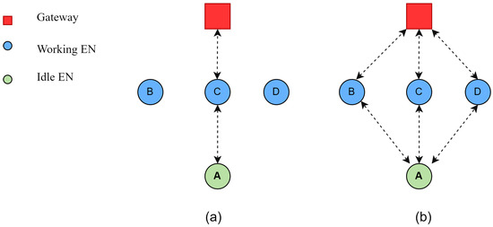
Figure 12.
IRE Additional packets overhead. During path exploration, the unicast method (a) must send two data packets to accomplish an end-to-end delivery. The entire procedure for method (b), however, requires four packets, as it involves broadcast messaging by nodes B, C, and D.
As shown in the Figure 13, when the number of ENs ranges from 100 to 600, the Additional Packet Overhead (APO) of BWA increases rapidly with the growing number of ENs, while the IRE method shows a much slower growth trend. This indicates that the IRE method demonstrates minimal dependence on the number of ENs, whereas BWA exhibits significant scalability limitations. The simulation results confirm that the IRE method delivers superior performance in large-scale, dense network deployments.
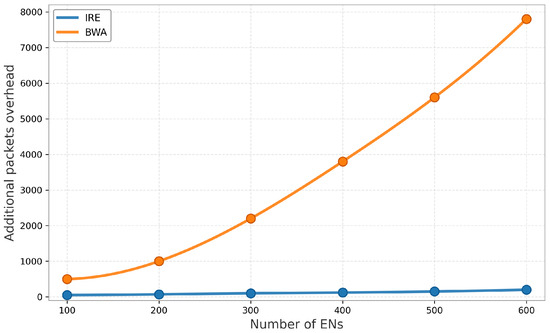
Figure 13.
Routing Overhead Comparison.
- (2)
- During the routing protocol design phase, performance was improved through multi-path and multi-channel approaches. The experiment utilized the RAK7258 module as the LoRa gateway, which supports a maximum of 8 communication channels. We designated one channel as the Primary Uplink Channel (Puc) and the remaining channels as Primary Receiving Channels (Prc). The frequency allocation is shown in Table 4.
 Table 4. Frequency Allocation Table.
During the phase of the routing protocol, all nodes operate exclusively on the Puc for communication, with each node performing route discovery by monitoring neighbor node messages on the Puc. This experiment employs a stratified sampling method to select 10 ENs nodes as test samples (2 from the first layer, 2 from the second layer, 3 from the third layer, and 3 from the fourth layer). The experimental setup is configured as follows: each ENs node transmits its first 5 data packets via the Puc before switching to the Prc for subsequent transmissions. With nodes generating data packets randomly at 10-s intervals, the network consequently operates entirely on the Puc for the initial 50-s period. To comprehensively evaluate the performance advantages of the Multi-path Multi-channel (MpMc) approach, this study implements two control schemes for comparative analysis: Single-path Single-channel (SpSc) and Multi-path Single-channel (MpSc).
The Figure 14 demonstrates that ENs employing the MpMc approach achieve significantly higher Packet Delivery Ratio (PDR) compared to the other two methods.The results indicate that single-path methods may lead to energy imbalance issues when contrasted with multi-path solutions.Experimental findings conclusively establish that MpMc effectively enhances PDR by preventing packet collisions through its optimized channel utilization strategy.
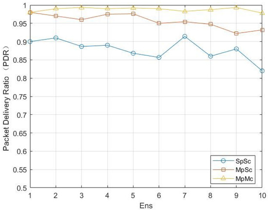
Figure 14.
Comparison chart of SpSc MpSc MpMc Packet Delivery Ratio.
- (3)
- Currently, various multi-path routing protocols (e.g., Ad hoc On-demand Multipath Distance Vector (AOMDV)) have been widely adopted in wireless sensor networks. To evaluate the performance of the LDSE protocol, this study deployed 10 ENs under identical configuration conditions, establishing network topologies based on both AOMDV and LDSE protocols respectively.As show in the Figure 15, experimental results demonstrate that the LDSE protocol exhibits significant advantages in PDR.
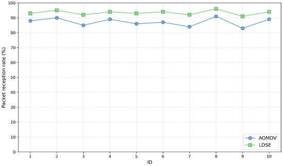 Figure 15. AOMDV & LDSE PDR Comparison.
Experimental results demonstrate that the LDSE protocol exhibits significant performance advantages over conventional AOMDV: its average PDR increases by 6.2 percentage points (93.4% vs 87.2%), with particularly outstanding performance in dynamic topology environments (e.g., nodes 3, 7, and 9). This superiority primarily stems from LDSE’s innovative load balancing mechanism and path quality optimization algorithm, which effectively reduce packet loss caused by network congestion and node mobility. In contrast, the AOMDV protocol’s static multi-path selection mechanism cannot dynamically avoid congested paths (as evidenced by packet loss on node 5’s alternate path) nor adapt effectively to network topology changes. The experimental results fully validate LDSE’s superior performance in dynamic environments, with its intelligent path selection mechanism significantly enhancing network reliability.
- (4)
- To validate the message delay performance of the LDSE protocol, we selected AODV as the benchmark for comparison (the status of AODV protocol as a standard MANET benchmark and its architectural contrast with the hierarchical design of our protocol). Figure 16 shows the hop count distribution from ENs to the gateway for both protocols, where LDSE demonstrates concentrated hops within the optimal 1–4 range while AODV exhibits higher and more dispersed hop counts—a key determin ant of network latency.
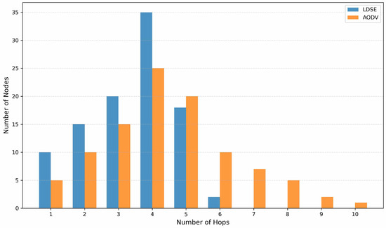 Figure 16. Hop distribution.
This divergence originates from fundamental architectural differences: LDSE’s centralized topology management enables dynamic path planning and real-time optimization through global network visibility, effectively eliminating redundant hops; whereas AODV’s distributed on-demand routing mechanism, lacking global state awareness, frequently results in suboptimal path selection. The experimental data conclusively validates LDSE’s significant advantage over conventional AODV in transmission latency performance.
- (5)
- To evaluate the performance of the LDSE protocol, we also conducted a quantitative comparison of key metrics against two state-of-the-art LoRa multi-hop routing schemes:the energy-efficient broadcasting protocol based on reinforcement learning by Chen et al. [28] and the MAGELLAN algorithm based on distributed Multi-Armed Bandits by Scarvaglieri et al. [29]. To ensure fairness, the comparison of routing protocols was conducted within a simulation environment of the same scale (simulation parameters are shown in Table 2. The comparative results are presented in Table 5.
 Table 5. Quantitative Performance Comparison with Advanced LoRa Multi-hop Routing Protocols.
The Energy Balance metric is quantified using the Coefficient of Variation (CV) of nodes’ residual energy, which is calculated as:
where represents the standard deviation of the residual energy across all nodes, and denotes the mean residual energy. A lower CV value indicates superior energy balancing across the network, as it reflects a more uniform distribution of energy consumption among nodes.
Comparative Analysis
In terms of communication reliability, LDSE achieves the highest average PDR of 93.4%. This is attributed to its MpMc communication mechanism, which effectively avoids collisions and congestion inherent in single-path and single-channel setups. MAGELLAN follows with 91.8%, as its distributed learning mechanism efficiently explores reliable paths. The scheme by Chen et al., due to its broadcast nature and the initial instability of Q-learning during the exploration phase, exhibits a relatively lower PDR.
Regarding transmission efficiency, the hierarchical structure and IRE mechanism of LDSE significantly reduce route discovery and control message exchanges, resulting in a control overhead of only 5%. This is substantially lower than the 12% overhead in Chen et al.’s scheme. The reduced overhead, combined with optimized path planning, leads to a shorter end-to-end delay, which is crucial for fire monitoring applications requiring rapid response.
Concerning energy balance, the standard deviation of 12.2% for MAGELLAN demonstrates its exceptional fairness-oriented design. LDSE also performs well with 12.5%, outperforming the scheme by Chen et al. This benefit stems from LDSE’s dynamic parent node selection mechanism, which prevents the premature energy depletion of hotspot nodes.
5.3. Concept Experiments
This section introduces proof-of-concept experiments to evaluate the practical performance of the LDSE protocol. The experimental setup adopts the RAK7258 module as the LoRa gateway.This module integrates the Semtech SX1302 chip (Camarillo, CA, USA) and the MT7628 processor (MediaTek, Hsinchu, Taiwan), and is capable of receiving 8 LoRa signals simultaneously. The terminal nodes are equipped with high-precision temperature and humidity sensors (SHT31) and image acquisition modules (OV5640), and the test is conducted using ten terminal nodes and one gateway.
Packet loss rate (PLR), as one of the key metrics for evaluating protocol performance, is of paramount importance.Therefore, this experiment adopts packet loss rate as the primary measure to assess the overall performance of routing protocols.The hardware configuration is the same as mentioned above. In routing protocol communications, the factors affecting packet reception rate mainly include the communication environment and packet size. The calculation method is defined as:
In the experimental setup, the communication parameters of the wireless node modules were configured as follows:
- Spreading Factor (SF): 9
- Bandwidth (BW): 125 kHz
- Coding Rate: 4/5
The test distance was set to 900 m, with data packets of 10 bytes and 30 bytes transmitted in total 2000 times.The final packet loss rate test results are presented in the Figure 17 and Figure 18.
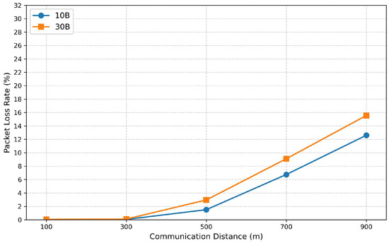
Figure 17.
PLR Comparison (LDSE).
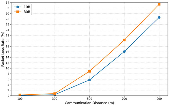
Figure 18.
PLR Comparison (AODV).
An analysis of Figure 17 and Figure 18 reveals that packet loss rate is significantly correlated with both packet size and communication distance. The data clearly demonstrates that as packet size increases and communication distance extends, the packet loss rate correspondingly rises. Furthermore, under identical experimental conditions, the LDSE routing protocol consistently outperforms the AODV protocol, exhibiting a lower packet loss rate.
This performance advantage indicates that LDSE is superior to AODV in routing efficiency.
The superior performance of LDSE can be attributed to several key technical advantages: It eliminates the need for frequent RREQ/RREP control packet switching, thereby reducing bandwidth contention and making it particularly suitable for long-distance and low-mobility networks. The dynamic transmission parameter adjustment mechanism is adopted to optimize the signal quality, and the optimal path from the node to the gateway can always be found. Therefore, the packet loss rate is effectively reduced.
In contrast, the dynamic routing method of the AODV protocol requires the continuous transmission of RREQ/RREP data packets. This not only consumes a large amount of bandwidth (the control packet loss rate is particularly high at long distances), but also requires frequent route reconstruction in the dynamic topology, thereby increasing the risk of packet loss.
The experimental results show that the architecture design of LDSE provides better performance and reliability than AODV, especially in wireless environments with long-distance communication and limited node mobility.
6. Conclusions and Future Work
This paper proposes an intelligent forest fire monitoring system based on a LoRa-Mesh wireless communication network, which adopts a distributed architecture with distinct functional components. End-node devices integrate environmental sensors (SHT31 for temperature/humidity) and camera modules (OV5640), coordinated by LoRa communication modules (SX1262). The gateway device (RAK7258) performs data aggregation, conducts preliminary threshold analysis, and manages system coordination. The deep learning-based fire identification (MobileNetV3) is deployed at the gateway level for initial processing, with complex analysis capabilities residing at the central server. All components operate under the innovative Layered Dynamic Synchronization Energy-saving (LDSE) protocol that orchestrates network communication.
Experimental results demonstrate significant advantages across key metrics:
- Communication Reliability: LDSE achieves 93.4% average packet delivery rate, 6.2% higher than AOMDV.
- Energy Efficiency: 42% reduction in energy consumption versus non-relay schemes.
- Transmission Efficiency: 35% throughput improvement over single-path approaches.
- Recognition Accuracy: 92.31% fire detection accuracy with 0.9 F1-score.
These quantitative results validate the system’s practical reliability for forest fire monitoring applications.
Future Work
In-depth Optimization of Intelligent Routing Algorithms: We will explore the deep integration of energy-aware routing algorithms with the LDSE protocol and investigate reinforcement learning-based dynamic path selection mechanisms to further optimize network energy consumption balance.
Large-Scale Network Deployment Validation: We plan to conduct large-scale node deployment tests in more complex terrain environments to validate the system’s reliability and scalability under extreme conditions.
Novel Energy Management Technologies: We will research the synergistic optimization of renewable energy harvesting technologies (such as solar power) with existing energy-saving strategies, exploring the feasibility of achieving node energy self-sufficiency.
Network Resilience Enhancement: We will focus on studying self-healing capabilities and fault-tolerant mechanisms of the network under abnormal conditions such as node failures and extreme weather, thereby improving the system’s robustness.
Author Contributions
Conceptualization, Z.L.; methodology, Z.L. and X.L.; software, X.L.; validation, Z.L. and X.L.; formal analysis, X.L.; investigation, Z.L. and J.S.; resources, J.S.; data curation, Z.L. and X.L.; writing—original draft preparation, Z.L.; writing—review and editing, X.L.; visualization, J.S.; supervision, X.L.; project administration, X.L. All authors have read and agreed to the published version of the manuscript.
Funding
The research work was supported by the Yunnan Key Labo ratory of Computer Technology Application Open Fund, the 2023 Basic Research Program of Yunnan Province (Grant No. 202301AT070388). We would like to express our sincere gratitude to our supervisor for his invaluable guidance, advice, and support throughout the research process.
Data Availability Statement
Data are contained within the article.
Conflicts of Interest
The authors declare no conflict of interest.
References
- Chicas, S.D.; Østergaard Nielsen, J. Who are the actors and what are the factors that are used in models to map forest fire susceptibility? A systematic review. Nat. Hazards 2022, 114, 2417–2434. [Google Scholar] [CrossRef]
- Brook, R.D.; Rajagopalan, S.; Pope, C.A., III; Brook, J.R.; Bhatnagar, A.; Diez-Roux, A.V.; Holguin, F.; Hong, Y.; Luepker, R.V.; Mittleman, M.A.; et al. Particulate matter air pollution and cardiovascular disease: An update to the scientific statement from the American Heart Association. Circulation 2010, 121, 2331–2378. [Google Scholar] [CrossRef] [PubMed]
- Pavlović, L.; Stojanović, D.; Mladenović, E.; Lakićević, M.; Orlović, S. Potential elevation shift of the European beech stands (Fagus sylvatica L.) in Serbia. Front. Plant Sci. 2019, 10, 849. [Google Scholar] [CrossRef] [PubMed]
- Homaei, M.H.; Salwana, E.; Shamshirb, S. An enhanced distributed data aggregation method in the Internet of Things. Sensors 2019, 19, 3173. [Google Scholar] [CrossRef] [PubMed]
- Xu, J.; Yao, J.; Wang, L.; Ming, Z.; Wu, K.; Chen, L. Narrowband Internet of Things: Evolutions, technologies, and open issues. IEEE Internet Things J. 2018, 5, 1449–1462. [Google Scholar] [CrossRef]
- Mane, S.Y. LPWAN’s–Overview, market scenario and performance analysis of Lora, Sigfox using NB-Fi range calculator. In Proceedings of the 2021 International Conference on Smart Generation Computing, Communication and Networking (SMART GENCON), Pune, India, 29–30 October 2021. [Google Scholar]
- Migabo, E.M.; Djouani, K.D.; Kurien, A.M. The narrowband Internet of Things (NB-IoT) resources management performance state of art, challenges, and opportunities. IEEE Access 2020, 8, 97658–97675. [Google Scholar] [CrossRef]
- Zhao, H.; Jiang, H. LTE-M system performance of integrated services based on field test results. In Proceedings of the 2016 IEEE Advanced Information Management, Communicates, Electronic and Automation Control Conference (IMCEC), Xi’an, China, 3–5 October 2016. [Google Scholar]
- Joris, L.; Dupont, F.; Laurent, P.; Bellier, P.; Stoukatch, S.; Redouté, J.M. An autonomous sigfox wireless sensor node for environmental monitoring. IEEE Sens. Lett. 2019, 3, 1–4. [Google Scholar] [CrossRef]
- Lavric, A.; Petrariu, A.I.; Popa, V. Long range sigfox communication protocol scalability analysis under large-scale, high-density conditions. IEEE Access 2019, 7, 35816–35825. [Google Scholar] [CrossRef]
- Bor, M.C.; Vidler, J.; Roedig, U. LoRa for the Internet of Things. In Proceedings of the International Conference on Embedded Wireless Systems and Networks (EWSN), Graz, Austria, 15–17 February 2016; Volume 16, pp. 361–366. [Google Scholar]
- Augustin, A.; Yi, J.; Clausen, T.; Townsley, W.M. A study of LoRa: Long range & low power networks for the internet of things. Sensors 2016, 16, 1466. [Google Scholar] [CrossRef] [PubMed]
- Sornin, N.; Luis, M.; Eirich, T.; Kramp, T.; Hersent, O. LoRaWAN Specification; LoRa Alliance: Fremont, CA, USA, 2015. [Google Scholar]
- Tang, R.; Aridas, N.K.; Abu Talip, M.S. Design of wireless sensor network for agricultural greenhouse based on improved zigbee protocol. Agriculture 2023, 13, 1518. [Google Scholar] [CrossRef]
- Palaniappan, A.; Muthiah, R.; Sundaram, M.T. ZigBee enabled IoT based intelligent lane control system for autonomous agricultural electric vehicle application. SoftwareX 2023, 23, 101512. [Google Scholar] [CrossRef]
- Ghoumid, K.; Ar-Reyouchi, D.; Benbrik, J.; Boukricha, S.; Elmazria, O. Optimization analysis of average message delivery time for healthcare monitoring using a developed NB-IoT technology in a smart city. Internet Things 2024, 27, 101290. [Google Scholar] [CrossRef]
- Osorio, A.; Calle, M.; Soto, J.D.; Candelo-Becerra, J.E. Routing in LoRaWAN: Overview and challenges. IEEE Commun. Mag. 2020, 58, 72–76. [Google Scholar] [CrossRef]
- Goratti, L.; Baykas, T.; Rasheed, T.; Kato, S. NACRP: A connectivity protocol for star topology wireless sensor networks. IEEE Wirel. Commun. Lett. 2015, 5, 120–123. [Google Scholar] [CrossRef]
- Chen, Y.; Shi, G.; Al-Quraan, M.; Sambo, Y.; Onireti, O.; Imran, M. LoRa mesh-5G integrated network for trackside smart weather monitoring. IEEE Trans. Veh. Technol. 2024, 73, 8903–8914. [Google Scholar]
- Lindquist, T.; Chambers, K.; Benish, N.; Berg, D.R.; Turkmen, A. LoRa Wireless Mesh Network for Lake Biology Study. In Proceedings of the 2024 Systems and Information Engineering Design Symposium (SIEDS), Charlottesville, VA, USA, 3 May 2024; pp. 47–50. [Google Scholar]
- Wu, D.; Liebeherr, J. A low-cost low-power LoRa mesh network for large-scale environmental sensing. IEEE Internet Things J. 2023, 10, 16700–16714. [Google Scholar] [CrossRef]
- Lehnert, A.; Gawantka, F.; During, J.; Just, F.; Reichenbach, M. XplAInable: Explainable AI Smoke Detection at the Edge. Big Data Cogn. Comput. 2024, 8, 50. [Google Scholar] [CrossRef]
- Basu, M.T.; Karthik, R.; Mahitha, J.; Reddy, V.L. IoT based forest fire detection system. Int. J. Eng. Technol. 2018, 7, 124–126. [Google Scholar] [CrossRef]
- Peruzzi, G.; Pozzebon, A.; Van Der Meer, M. Fight fire with fire: Detecting forest fires with embedded machine learning models dealing with audio and images on low power iot devices. Sensors 2023, 23, 783. [Google Scholar] [CrossRef] [PubMed]
- Vega-Rodríguez, R.; Sendra, S.; Lloret, J.; Romero-Díaz, P.; Garcia-Navas, J.L. Low cost LoRa based network for forest fire detection. In Proceedings of the 2019 Sixth International Conference on Internet of Things: Systems, Management and Security (IOTSMS), Granada, Spain, 22–25 October 2019; pp. 177–184. [Google Scholar]
- Dharmesh, M.; Diwakar, B.; Naveen Kumar, S.; Gurubaran, K.; Deepak Athipan, A.M.B.; Bino, J.; Bhuvaneswari, P.T.V. FireWatch: LoRa-Connected Fire Detection and Monitoring System. In Proceedings of the 2023 International Conference on Next Generation Electronics (NEleX), Vellore, India, 14–16 December 2023; pp. 1–5. [Google Scholar]
- Dubey, A.K.; Sirohi, S.; Anwer, Q.; Alam, S.; Sahil, M. LORA Communication Model Design for Environmental Data of Natural Calamities Area. In Proceedings of the 2024 International Conference on Emerging Technologies and Innovation for Sustainability (EmergIN), Greater Noida, India, 20–21 December 2024; pp. 147–151. [Google Scholar] [CrossRef]
- Chen, X.; Mao, Y.; Xu, Y.; Yang, W.; Chen, C.; Lei, B. Energy-efficient multi-hop LoRa broadcasting with reinforcement learning. Ad Hoc Netw. 2025, 165, 103450. [Google Scholar]
- Scarvaglieri, A.; Panebianco, A.; Busacca, F. MAGELLAN: A Distributed MAB-based Algorithm for Energy-fair and Reliable Routing in Multi-hop LoRa Networks. In Proceedings of the IEEE Global Communications Conference (GLOBECOM), Cape Town, South Africa, 8–12 December 2024; pp. 1–6. [Google Scholar]
Disclaimer/Publisher’s Note: The statements, opinions and data contained in all publications are solely those of the individual author(s) and contributor(s) and not of MDPI and/or the editor(s). MDPI and/or the editor(s) disclaim responsibility for any injury to people or property resulting from any ideas, methods, instructions or products referred to in the content. |
© 2025 by the authors. Licensee MDPI, Basel, Switzerland. This article is an open access article distributed under the terms and conditions of the Creative Commons Attribution (CC BY) license (https://creativecommons.org/licenses/by/4.0/).