A UV-C LED Sterilization Lamp Driver Circuit with Boundary Conduction Mode Control Power Factor Correction †
Abstract
1. Introduction
2. Analysis of Operational Modes and Elaboration on the Control Concepts in the Proposed UV-C LED Sterilization Lamp Driver Circuit with Boundary Conduction Mode Power Factor Correction
- (a)
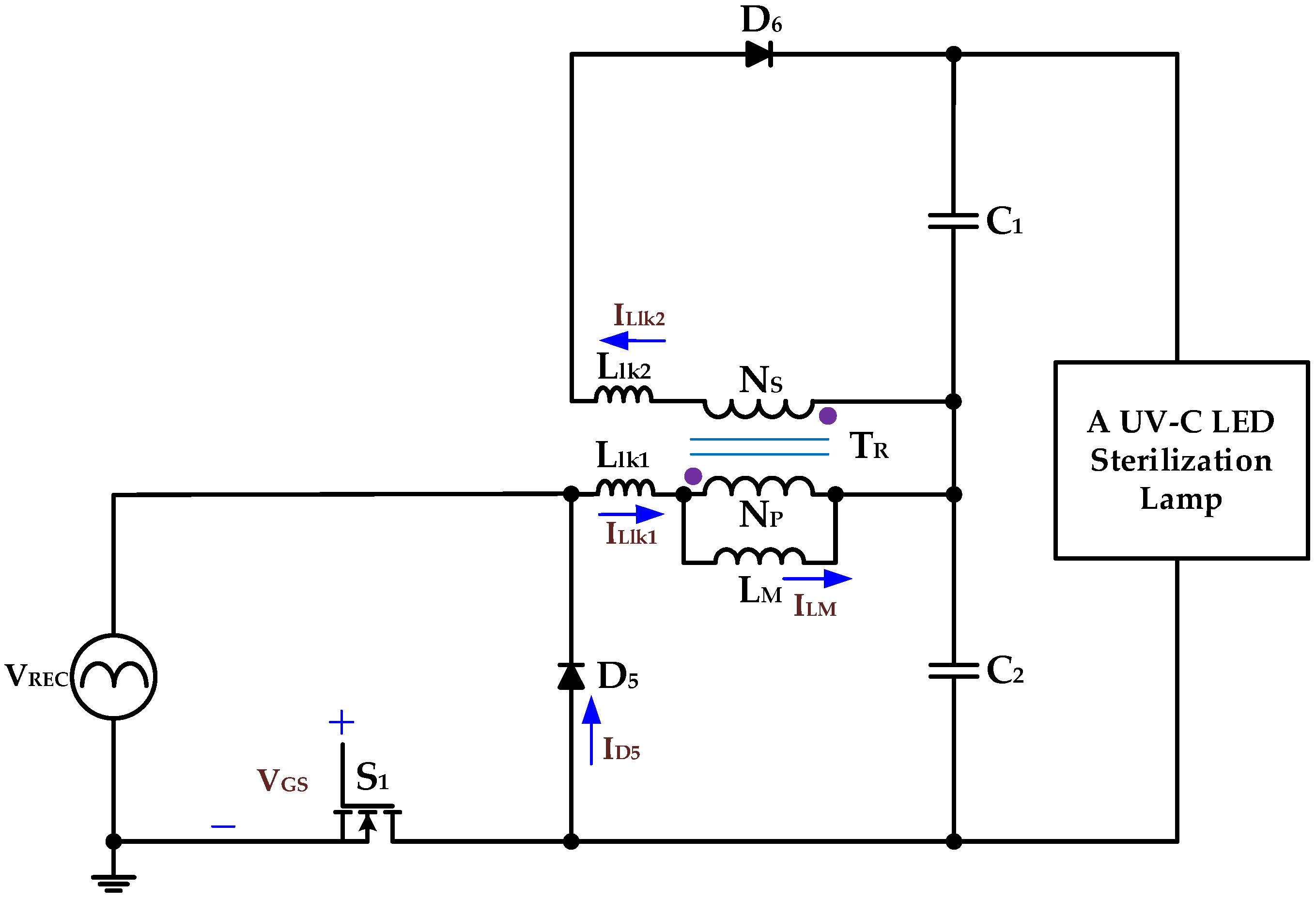
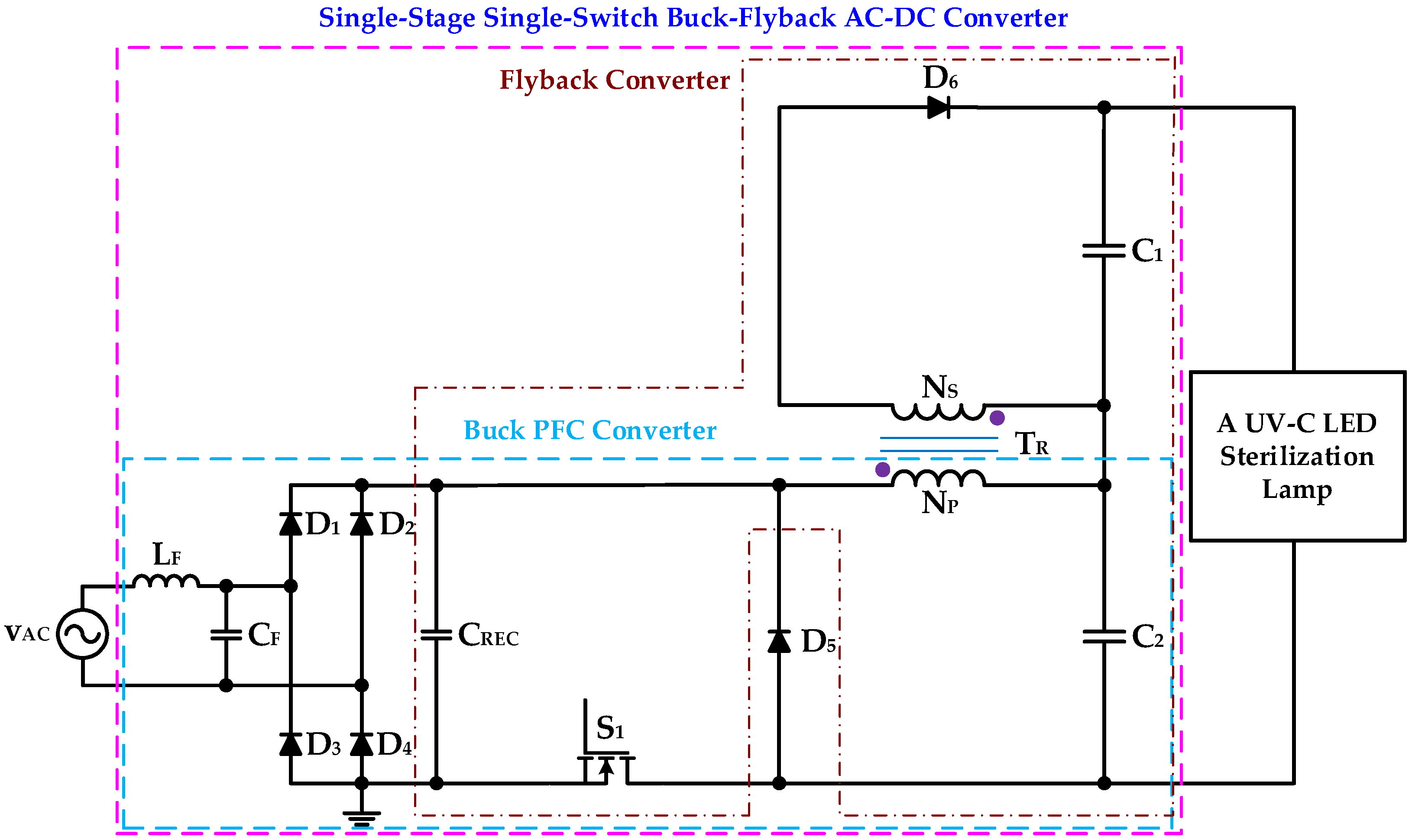
- The AC input voltage vAC is assumed to be rectified by a full-wave bridge and subsequently filtered by capacitor CREC, resulting in a DC voltage source denoted as VREC.
- (b)
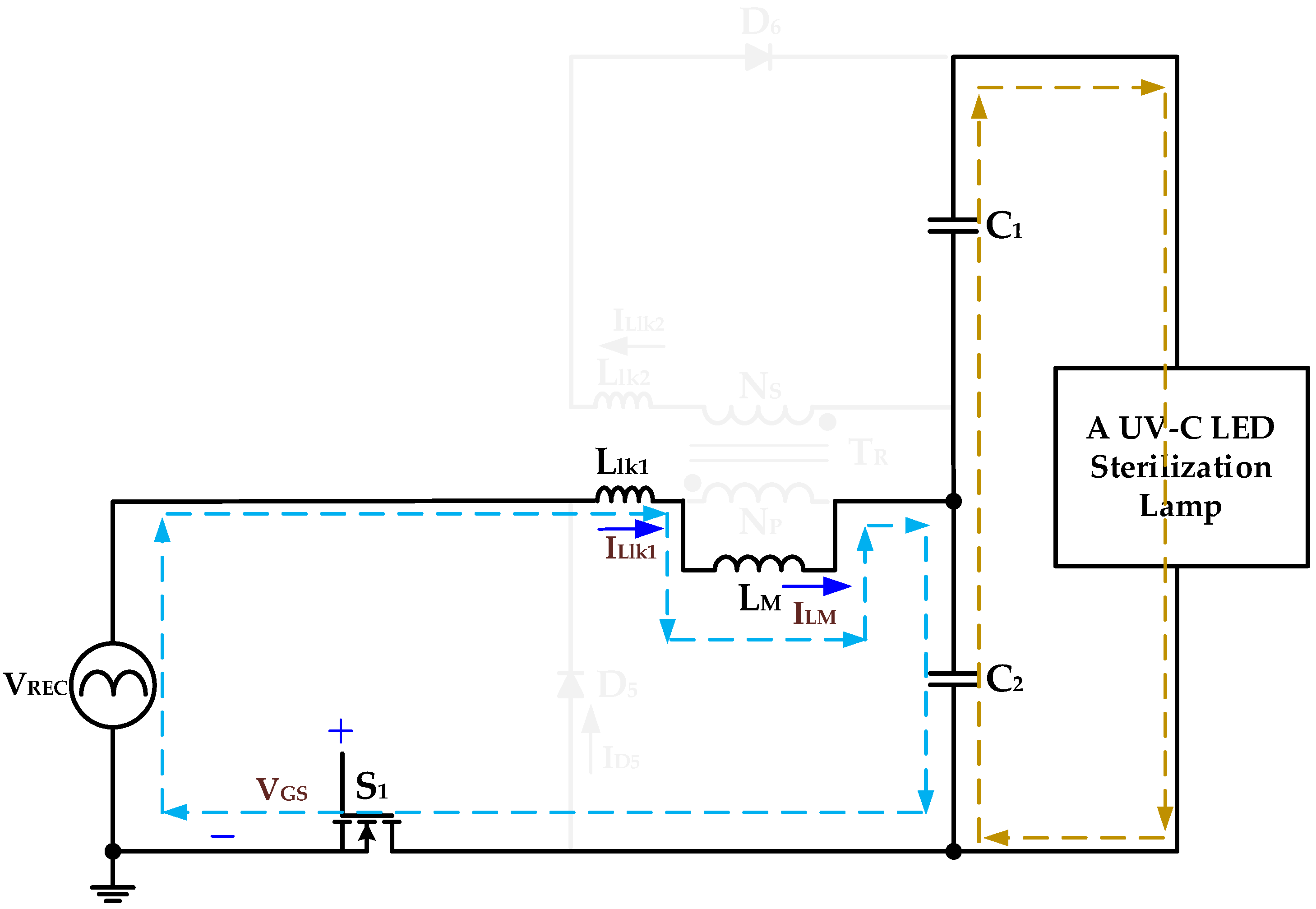
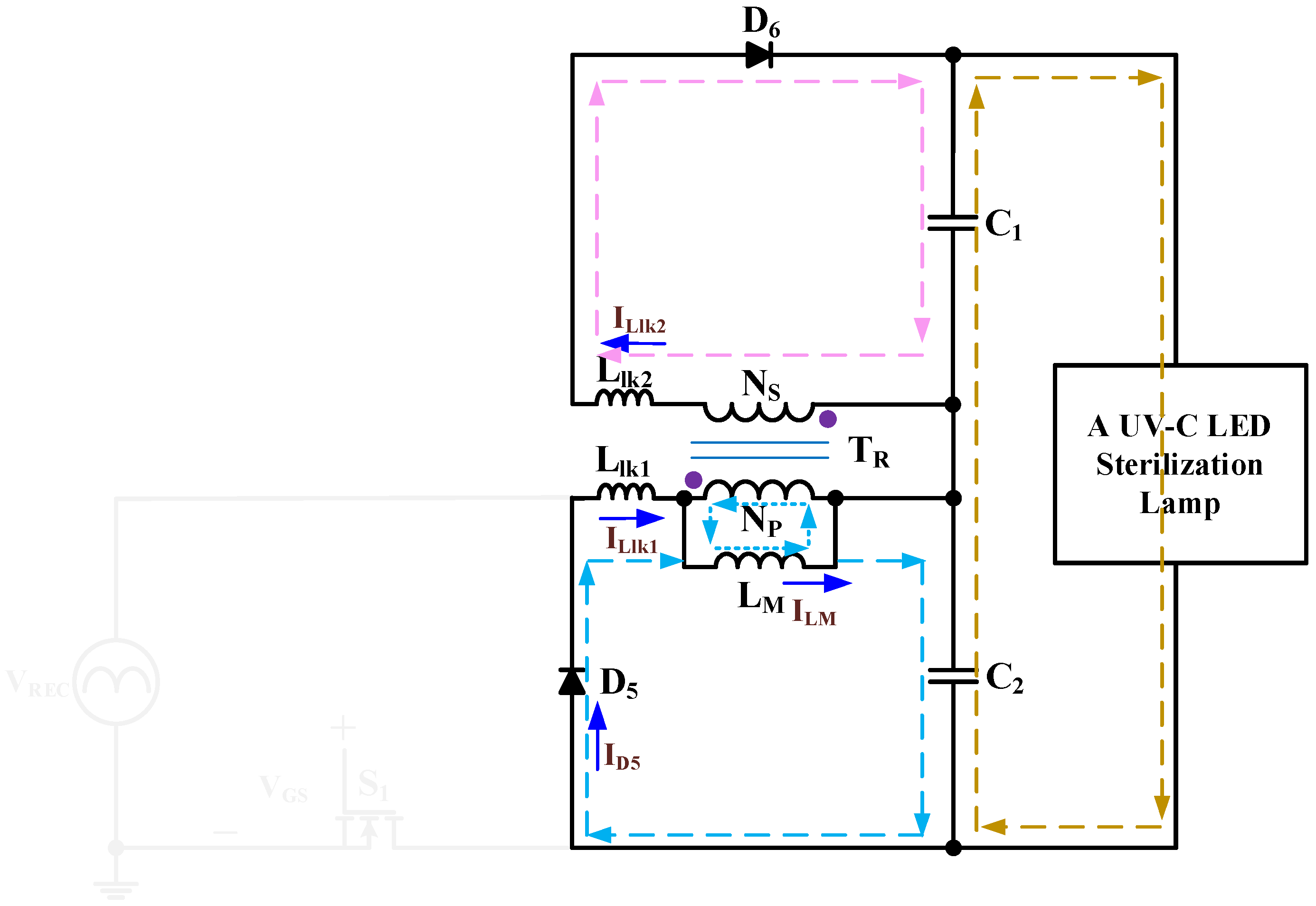
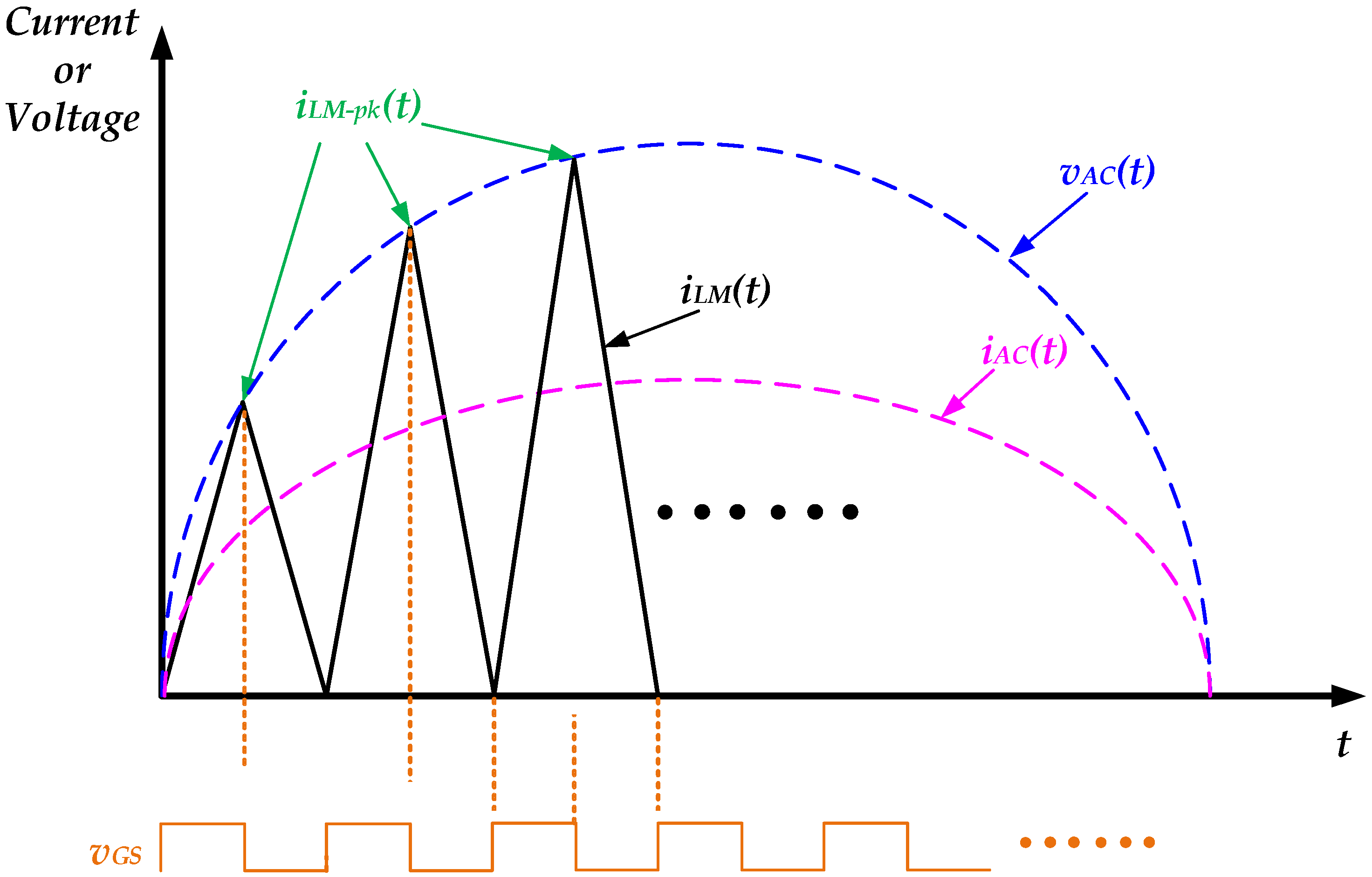
- To achieve input current shaping, the power switch is operated under a transition mode pulse-width modulation (PWM) strategy, characterized by a fixed turn-on time and variable switching frequency. Consequently, the duty cycle of the power switch S1 is set to 0.5. For simplicity, the effects of the switch’s parasitic diode and parasitic capacitance are neglected.
- (c)
- The magnetizing inductor LM is designed to operate in boundary conduction mode with a peak current control scheme to ensure effective power factor correction.
- (d)
- The leakage inductances on the primary and secondary sides of the transformer TR are represented by Llk1 and Llk2, respectively.
- (e)
- All remaining circuit components are considered ideal for the purpose of this analysis.

- (1)
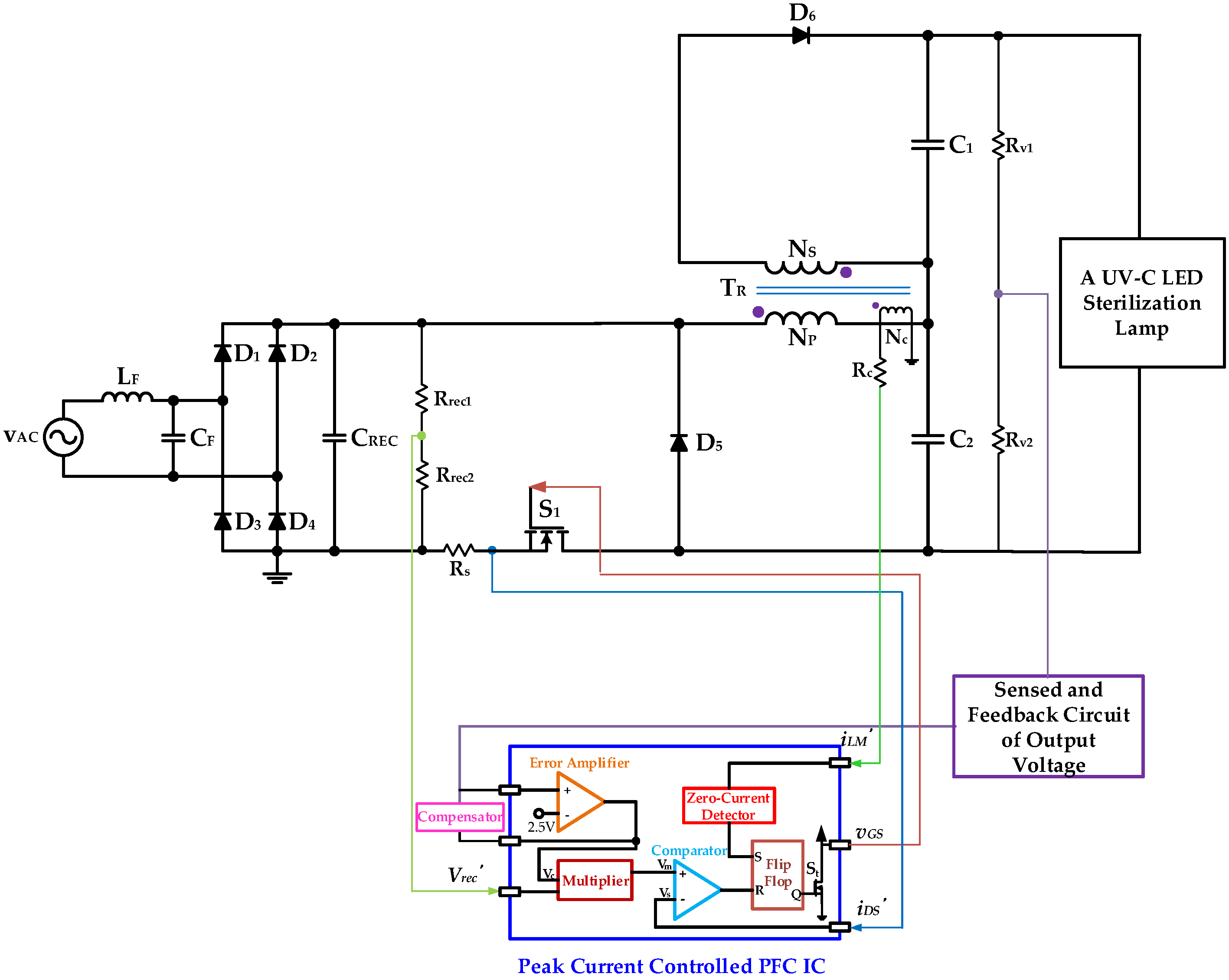
- The output voltage of the UV-C LED sterilization lamp is obtained from the detection resistors Rv1 and Rv2, and then sent to the error amplifier through the output voltage detection and feedback circuit and feedback compensation circuit to compare with the 2.5-volt DC voltage level to obtain a voltage signal Vc. After the AC input voltage is rectified by a full-wave bridge rectifier, a voltage signal Vrec’ is obtained from the detection resistors Rrec1 and Rrec2, which, together with the voltage signal Vc, are fed into a multiplier to obtain a voltage signal Vm. The current signal iDS’ flowing through the power switch S1 is converted into a voltage signal Vs by the detection resistor Rs. A comparator compares the two voltage signals Vm and Vs and sends them to the Reset (R) pin of the Flip-Flop, and when the voltage signals Vm and Vs are equal, the power switch S1 is turned off by this mechanism.
- (2)
- The current iLM’ flowing through the magnetizing inductor LM is detected by adding the third winding Nc of the transformer TR and connecting a circuit Rc in series, and the return current iLM’ is proportional to the output current of the UV-C LED sterilization lamp. This return current iLM’ is proportional to the output current of the UV-C LED sterilization lamp. The return current iLM’ is then fed to the Set (S) pin of the inverter through the zero current detector. Since the magnetizing inductor is designed to operate in the boundary conduction mode, when the current iLM’ flowing through the magnetizing inductor LM drops to zero, the power switch S1 is activated by this mechanism.
3. Design Guideline of the UV-C LED Sterilization Lamp Driver Circuit with BCM PFC
3.1. Design Guideline of the Magnetizing Inductor LM in the Transformer TR
3.2. Design Guideline of the Turns Ratio of Transformer TR
3.3. Design Guideline of the Output Capacitors C1 and C2
4. Experimental Results of the Proposed UV-C LED Sterilization Lamp Driver Circuit with BCM PFC
5. Conclusions
Author Contributions
Funding
Data Availability Statement
Conflicts of Interest
References
- Kebbi, Y.; Muhammad, A.I.; Sant’ANa, A.S.; Prado-Silva, L.D.; Liu, D.; Ding, T. Recent advances on the application of UV-LED technology for microbial inactivation: Progress and mechanism. Compr. Rev. Food Sci. Food Saf. 2020, 19, 3501–3527. [Google Scholar] [CrossRef] [PubMed]
- Gąstoł, M.; Błaszczyk, U. Effect of Magnetic Field and UV-C Radiation on Postharvest Fruit Properties. Agriculture 2024, 14, 1167. [Google Scholar] [CrossRef]
- Duarte-Sierra, A.; Charles, M.T.; Arul, J. UV-C hormesis: A means of controlling diseases and delaying senescence in fresh fruits and vegetables during storage. In Postharvest Pathology of Fresh Horticultural Produce; CRC Press: Boca Raton, FL, USA, 2019; pp. 539–594. [Google Scholar]
- Shatalov, M.; Jain, R.; Saxena, T.; Dobrinsky, A.; Shur, M. Chapter Two—Development of Deep UV LEDs and Current Problems in Material and Device Technology. In Semiconductors and Semimetals; Elsevier: Amsterdam, The Netherlands, 2017; Volume 96, pp. 45–83. [Google Scholar]
- Guo, L.; Azam, S.R.; Guo, Y.; Liu, D.; Ma, H. Germicidal efficacy of the pulsed magnetic field against pathogens and spoilage microorganisms in food processing: An overview. Food Control 2022, 136, 108496. [Google Scholar] [CrossRef]
- Koutchm, T.; Popović, V.; Green, A. Chapter 1—Overview of Ultraviolet (UV) LEDs Technology for Applications in Food Production. In Ultraviolet LED Technology for Food Applications; Academic Press: Cambridge, MA, USA, 2019; pp. 1–23. [Google Scholar]
- Yemmireddy, V.; Adhikari, A.; Moreira, J. Effect of ultraviolet light treatment on microbiological safety and quality of fresh produce: An overview. Front. Nutr. 2022, 9, 871243. [Google Scholar] [CrossRef] [PubMed]
- Akgün, M.P.; Ünlütürk, S. Effects of ultraviolet light emitting diodes (LEDs) on microbial and enzyme inactivation of apple juice. Int. J. Food Microbiol. 2017, 260, 65–74. [Google Scholar] [CrossRef]
- Kaya, Z.; Yıldız, S.; Ünlütürk, S. Effect of UV-C irradiation and heat treatment on the shelf life stability of a lemon–melon juice blend: Multivariate statistical approach. Innov. Food Sci. Emerg. Technol. 2015, 29, 230–239. [Google Scholar] [CrossRef]
- Guan, Z.; Liu, P.; Zhou, T.; Zhou, L.; Zhang, D.; Xie, Q.; Yu, Q.; He, Y.; Wang, S.; Wang, X.; et al. Study on the Light Field Regulation of UVC-LED Disinfection for Cold Chain Transportation. Appl. Sci. 2022, 12, 1285. [Google Scholar] [CrossRef]
- Darré, M.; Vicente, A.R.; Cisneros-Zevallos, L.; Artés-Hernández, F. Postharvest ultraviolet radiation in fruit and vegetables: Applications and factors modulating its efficacy on bioactive compounds and microbial growth. Foods 2022, 11, 653. [Google Scholar] [CrossRef]
- Liang, J.-J.; Liao, C.-C.; Chang, C.-S.; Lee, C.-Y.; Chen, S.-Y.; Huang, S.-B.; Yeh, Y.-F.; Singh, K.J.; Kuo, H.-C.; Lin, Y.-L.; et al. The Effectiveness of Far-Ultraviolet (UVC) Light Prototype Devices with Different Wavelengths on Disinfecting SARS-CoV-2. Appl. Sci. 2021, 11, 10661. [Google Scholar] [CrossRef]
- Juarez-Leon, F.A.; Soriano-Sanchez, A.G.; Rodriguez-Licea, M.A.; Perez-Pinal, F.J. Design and Implementation of a Germicidal UVC-LED Lamp. IEEE Access 2020, 8, 196951–196962. [Google Scholar] [CrossRef]
- Alonso, J.M.; Costa, M.A.D.; Ordiz, C. Integrated Buck-Flyback Converter as a High-Power-Factor Off-Line Power Supply. IEEE Trans. Ind. Electron. 2008, 55, 1090–1100. [Google Scholar] [CrossRef]
- Gacio, D.; Alonso, J.M.; Calleja, A.J.; García, J.; Rico-Secades, M. A Universal-Input Single-Stage High-Power-Factor Power Supply for HB-LEDs Based on Integrated Buck–Flyback Converter. IEEE Trans. Ind. Electron. 2011, 58, 589–599. [Google Scholar] [CrossRef]
- Abdelmessih, G.Z.; Alonso, J.M.; Costa, M.A.D. Loss Analysis for Efficiency Improvement of the Integrated Buck–Flyback LED Driver. IEEE Trans. Ind. Appl. 2018, 54, 6543–6553. [Google Scholar] [CrossRef]
- Abdelmessih, G.Z.; Alonso, J.M.; Tsai, W.-T. Analysis and Experimentation on a New High Power Factor Off-Line LED Driver Based on Interleaved Integrated Buck Flyback Converter. IEEE Trans. Ind. Appl. 2019, 55, 4359–4369. [Google Scholar] [CrossRef]
- Luz, P.C.V.; Bolán, P.E.; Maboni, T.; Cosetin, M.R.; da Silva, M.F.; Prado, R.N.D. An integrated insulated Buck-Boost-Flyback converter to feed LED’s lamps to street lighting with reduced capacitances. In Proceedings of the 2014 11th IEEE/IAS International Conference on Industry Applications, Juiz de Fora, Brazil, 7–10 December 2014; pp. 1–6. [Google Scholar]
- Divya, K.M.; Parackal, R. High power factor integrated buck-boost flyback converter driving multiple outputs. In Proceedings of the 2015 Online International Conference on Green Engineering and Technologies (IC-GET), Coimbatore, India, 27 November 2015; pp. 1–5. [Google Scholar]
- Cheng, C.-A.; Chung, T.-Y. A Novel Integrated Driver with PFC for Supplying Light-Emitting Diodes. In Proceedings of the 41th Annual Conference of the IEEE Industrial Electronics Society (IECON 2015), Yokohama, Japan, 9–12 November 2015; pp. 3514–3518. [Google Scholar]
- Poorali, B.; Adib, E. Analysis of the Integrated SEPIC-Flyback Converter as a Single-Stage Single-Switch Power-Factor-Correction LED Driver. IEEE Trans. Ind. Electron. 2016, 63, 3562–3570. [Google Scholar] [CrossRef]
- Cheng, C.-A.; Chen, Y.-L.; Chen, Y.-J.; Lai, S.-W. A Novel Cost-Effective AC-DC Power Supply for Indoor LED Lighting Applications. In Proceedings of the 2019 IEEE PES Asia-Pacific Power and Energy Engineering (APPEEC), Macao, China, 1–4 December 2019; pp. 1–3. [Google Scholar]
- Keogh, B. Power Factor Correction Using the Buck Topology—Efficiency Benefits and Practical Design Considerations. 2010 Texas Instruments Power Supply Design Seminar. Available online: https://e2e.ti.com/cfs-file/__key/communityserver-discussions-components-files/196/App_2D00_Note_5F00_Buck_2D00_PFC_5F00_SEM_2D00_1900_5F00_slup264.pdf (accessed on 1 October 2025).
- Keogh, B.; Young, G.; Wegner, H.; Gillmor, C. Design considerations for high efficiency Buck PFC with Half-Bridge regulation stage. In Proceedings of the 2010 Twenty-Fifth Annual IEEE Applied Power Electronics Conference and Exposition (APEC), Palm Springs, CA, USA, 21–25 February 2010; pp. 1384–1391. [Google Scholar]
- Dahri, A.F.; Sahito, A.A.; Memon, A.H.; Memon, S.A. A review on Buck topology-based PFC Conversion Techniques. Int. J. Eng. Des. Innov. 2020, 2, 33–42. [Google Scholar]
- Zeng, H.; Zhang, J. An improved control scheme for buck PFC converter for high efficiency adapter application. In Proceedings of the 2012 IEEE Energy Conversion Congress and Exposition (ECCE), Raleigh, NC, USA, 15–20 September 2012; pp. 4569–4576. [Google Scholar]
- Chen, B.; Xie, Y.; Huang, F.; Chen, J. A Novel Single-phase Buck PFC Converter Based on One-cycle Control. In Proceedings of the IEEE Power Electronics and Motion Control Conference (IPEMC), Shanghai, China, 14–16 August 2006; Volume 2, pp. 1–5. [Google Scholar]
- Cheng, C.-A.; Lan, L.-F.; Hou, S.-H.; Lin, C.-K. A Single-Stage Electronic Lighting Driver for a Deep Ultraviolet LED Disinfection and Sterilization Lamp. In Proceedings of the Workshop on Wide Bandgap Power Devices and Applications in Asia (WiPDA-Asia 2023), Hsinchu, Taiwan, 27–29 August 2023; pp. 1–3. [Google Scholar]
- Cheng, C.-A.; Chang, C.-H.; Cheng, H.-L.; Chang, E.-C.; Lan, L.-F.; Hou, S.-H.; Lin, C.-K. A Single-Stage Electronic Lighting Driver Circuit Utilizing SiC Schottky Diodes for Supplying A Deep Ultraviolet LED Disinfection and Sterilization Lamp. Electronics 2024, 13, 3048. [Google Scholar] [CrossRef]
- Adragna, C. L6561, Enhanced Transition Mode Power Factor Corrector. In AN966 Application Note; STMicroelectronics: Geneva, Switzerland, 2003; pp. 1–23. [Google Scholar]
- Ahmad, S.; Tan, N.M.L.; Baharuddin, M.Z.; Buticchi, G. A High-Performance Isolated SEPIC Converter for Non-Electrolytic LED Lighting. IEEE Access 2021, 9, 149894–149905. [Google Scholar] [CrossRef]
- Gürçam, K.; Almalı, M.N. A High-Efficiency Single-Stage Isolated Sepic-Flyback AC–DC Led Driver. Electronics 2023, 12, 4946. [Google Scholar] [CrossRef]




| Parameter | UV Mercury Lamp | UV-C LED |
|---|---|---|
| Peak wavelength | ~254 nm | 255–280 nm (tunable) |
| Preheating requirement | Yes | No |
| Warm-up time | 1–5 min | Instant-on |
| Lamp life | 5000–8000 h | 10,000–50,000 h |
| Environmental impact | Contains mercury (toxic, disposal issues) | Mercury-free (environmentally friendly) |
| Size & form factor | Large, fragile glass tube | Compact, robust, solid-state |
| Initial cost | Low | Higher |
| Radiant power output | High (suitable for large-area applications) | Lower (requires optimized placement) |
| Energy efficiency | Moderate | High |
| Parameter | Value |
|---|---|
| Input AC Voltage vAC | 110 V |
| Rated Output Power PO | 10.8 W |
| Rated Output Voltage VO | 90 V |
| Rated Output Current IO | 120 mA |
| Component | Value |
|---|---|
| Filter Inductor LF | 3 mH |
| Filter Capacitor CF | 220 nF |
| Diodes D1, D2, D3, D4 | MUR460 |
| Capacitor CREC | 470 nF |
| Power Switch SB | SPW47N60C3 |
| Turns Ratio n of Transformer TR | n = NP/NS = 2 |
| Magnetizing Inductor LM | 2.67 mH |
| Leakage Inductors Llk1, Llk2 | 26.7 μH, 9.61 μH |
| Diodes D5, D6 | MUR460 |
| Output Capacitor CO1, CO2 | 150 μF |
| Parameters | Values |
|---|---|
| Mean value of the output voltage | 90.87 V |
| Peak-to-peak value of the output voltage | 1.18 V |
| Ripple factor of the output voltage | 1.298% |
| Mean value of the output current | 126 mA |
| Peak-to-peak value of the output current | 5.6 mA |
| Ripple factor of the output current | 4.44% |
| Item | Existing Single-Stage Single-Switch AC-DC LED Driver in Reference [31] | Existing Single-Stage Single-Switch AC-DC LED Driver in Reference [32] | Proposed Single-Stage Single-Switch AC-DC LED Driver |
|---|---|---|---|
| Circuit Topology | Combining an isolated SEPIC converter with a lossless snubber | Combining a Vienna converter with an isolated SEPIC-flyback converter | Combining a buck PFC converter with a flyback converter |
| Input AC Voltage | 90~240 V | 220 V | 110 V |
| Output Power | 18 W (30 V/0.6 A) | 18 W (30 V/0.6 A) | 10.8 W (90 V/0.12 A) |
| Number of Required Power Switches | 1 | 1 | 1 |
| Number of Required Capacitors | 4 | 4 | 3 |
| Number of Required Magnetic Components | 4 | 3 | 2 |
| Number of Required Diodes | 7 | 3 | 6 |
| Measured Power Factor | 0.97 at 110 V | 0.97 | 0.9164 |
| Measured Circuit Efficiency | 93% at 110 V | 95% | 92.2% |
Disclaimer/Publisher’s Note: The statements, opinions and data contained in all publications are solely those of the individual author(s) and contributor(s) and not of MDPI and/or the editor(s). MDPI and/or the editor(s) disclaim responsibility for any injury to people or property resulting from any ideas, methods, instructions or products referred to in the content. |
© 2025 by the authors. Licensee MDPI, Basel, Switzerland. This article is an open access article distributed under the terms and conditions of the Creative Commons Attribution (CC BY) license (https://creativecommons.org/licenses/by/4.0/).
Share and Cite
Cheng, C.-A.; Lee, C.-M.; Chang, E.-C.; Lin, C.-K.; Lan, L.-F.; Hou, S.-H. A UV-C LED Sterilization Lamp Driver Circuit with Boundary Conduction Mode Control Power Factor Correction. Electronics 2025, 14, 3985. https://doi.org/10.3390/electronics14203985
Cheng C-A, Lee C-M, Chang E-C, Lin C-K, Lan L-F, Hou S-H. A UV-C LED Sterilization Lamp Driver Circuit with Boundary Conduction Mode Control Power Factor Correction. Electronics. 2025; 14(20):3985. https://doi.org/10.3390/electronics14203985
Chicago/Turabian StyleCheng, Chun-An, Ching-Min Lee, En-Chih Chang, Cheng-Kuan Lin, Long-Fu Lan, and Sheng-Hong Hou. 2025. "A UV-C LED Sterilization Lamp Driver Circuit with Boundary Conduction Mode Control Power Factor Correction" Electronics 14, no. 20: 3985. https://doi.org/10.3390/electronics14203985
APA StyleCheng, C.-A., Lee, C.-M., Chang, E.-C., Lin, C.-K., Lan, L.-F., & Hou, S.-H. (2025). A UV-C LED Sterilization Lamp Driver Circuit with Boundary Conduction Mode Control Power Factor Correction. Electronics, 14(20), 3985. https://doi.org/10.3390/electronics14203985


