Abstract
The rapid evolution of modern power systems, driven by the large-scale integration of renewable energy sources and the emergence of smart grids, presents new challenges in maintaining grid stability, power quality, and control reliability. As critical interfacing elements, three-phase pulse width modulation (PWM) converters must now ensure resilient and efficient operation under increasingly adverse and dynamic grid conditions. This paper proposes an adaptive neural network-based virtual flux (VF) estimator for sensorless predictive direct power control (PDPC) of PWM converters under nonideal grid voltage conditions. The proposed estimator is realized using an adaptive linear neuron (ADALINE) configured as a quadrature signal generator, offering robustness against grid voltage disturbances such as voltage unbalance, DC offset and harmonic distortion. In parallel, a PDPC scheme based on the extended pq theory is developed to reject active-power oscillations and to maintain near-sinusoidal grid currents under unbalanced conditions. The resulting VF-based PDPC (VF-PDPC) strategy is validated via real-time simulations on the OPAL-RT platform. Comparative analysis confirms that the ADALINE-based estimator surpasses conventional VF estimation techniques. Moreover, the VF-PDPC achieves superior performance over conventional PDPC and extended pq theory-based PDPC strategies, both of which rely on physical voltage sensors, confirming its robustness and effectiveness under non-ideal grid conditions.
1. Introduction
Electrical energy generation from renewable sources, such as wind energy conversion systems, photovoltaic systems or micro-hydropower plants, has grown steadily in recent years [1]. To enable power transfer to the grid, these systems incorporate a source-side converter, a DC bus, and a grid-side converter (GSC), as illustrated in Figure 1 [2,3]. An inductive filter is often placed between the GSC and the grid to mitigate harmonic distortion in the currents at the point of common coupling (PCC), caused by the pulse width modulation (PWM) output voltage of the GSC.
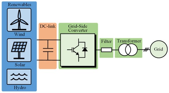
Figure 1.
Topology of a grid-connected renewable energy system.
Traditionally, GSC control relies on voltage-oriented control, which involves indirect regulation of active and reactive power through a current control loop [4]. This approach requires precise decoupling of current components in the rotating dq reference frame and accurate grid synchronization via a phase-locked loop (PLL). Furthermore, achieving satisfactory dynamic performance depends on the careful tuning of current regulators. In response to these constraints, direct power control (DPC) has emerged as a promising alternative. By directly controlling active and reactive power, DPC is characterized by a simple control structure, excellent dynamic response, and high robustness to parameter variations [5]. However, conventional DPC, which relies on a predefined lookup table, has several limitations [6,7]: a variable switching frequency that produces a wide harmonic spectrum, thereby complicating filter design; the fact that it cannot simultaneously regulate active and reactive power without generating steady-state ripples; and the need for a high sampling frequency to maintain control accuracy. To overcome these limitations, several advanced strategies have been developed. Optimized lookup tables [8] and fuzzy-logic-based selection schemes [9,10] have been introduced to reduce power ripples. Moreover, the integration of space vector modulation (SVM) has enabled operation at a constant switching frequency [11]. More recently, model-based predictive DPC (MPDPC) has emerged as a leading solution [5,12]. By selecting the voltage vector that minimizes a cost function based on power errors at each sampling step, MPDPC offers excellent dynamic and steady-state performance. Despite its advantages, conventional MPDPC imposes a variable switching frequency, induces significant computational burden, and remains sensitive to grid-voltage disturbances. Simplified variants directly calculate a reference voltage vector to reduce the computational load while maintaining high performance [13,14]. Concurrently, deadbeat predictive control is widely used for current control [15,16] and power control [17,18] of GSCs. The advantages of this approach include a constant switching frequency, the elimination of the PLL, and a fast dynamic response.
Although highly effective under ideal grid conditions, these control strategies exhibit significant performance degradation under non-ideal grid conditions, characterized by unbalance, harmonic distortion or DC offset. In practical applications, such disturbances are frequently encountered in renewable energy systems. For example, wind turbines often suffer from voltage unbalances during grid faults and PV arrays are subject to harmonic distortions caused by nonlinear loads, while micro-hydropower systems are prone to DC offset due to sensor drifts and measurement errors. These issues significantly affect current quality and power stability, thereby motivating the need for robust control strategies. Enhanced DPC approaches have incorporated compensation schemes to suppress power oscillations and maintain sinusoidal current waveforms; however, their implementation remains complex and computationally intensive, because it requires extracting positive and negative sequence components of the grid voltages [18]. This complexity originates from the use of conventional pq theory, which is inadequate for unbalanced grid conditions. To address this limitation, the extended pq theory was introduced, enabling the natural suppression of current distortions and power oscillations without requiring additional decompositions. When integrated into predictive DPC (PDPC) schemes [19,20], this approach enhances steady-state performance under unbalanced grid conditions. Nonetheless, the simultaneous mitigation of voltage-harmonic effects and DC offset components constitutes an underexplored research area.
On the other hand, improvements in GSC performance can also be achieved by adopting voltage sensorless control strategies [18]. Indeed, replacing physical sensors with software ones is a relevant approach to reduce the overall system cost, increase its reliability, and ensure continuity of service in the event of hardware failure [18]. Due to its simplicity, many studies have focused on approaches based on the virtual flux (VF) concept. This concept replaces voltage measurement with an estimation of the VF, obtained by integrating the three-phase grid voltages in the αβ frame. This operation is typically performed by a first-order low-pass filter (LPF) to avoid drift and saturation issues inherent to pure integrators [21]. However, this solution introduces amplitude and phase errors that degrade estimation accuracy and dynamic performance. To overcome these limitations, more advanced strategies have been proposed, such as the adaptive first-order LPF [7], second-order LPF [22], second-order generalized integrators (SOGIs) [23,24], or VF estimators with initial bias compensation [25,26]. Although these methods provide notable improvements, they have their own constraints. Some have only been validated under ideal grid conditions [25], while others suffer from processing delays due to cascaded structures [7,22]. Furthermore, the resonant structure of the SOGI makes it particularly sensitive to the chosen discretization method and DC offset components originating from the measurement and conditioning operations [23,24]. To address this issue, the authors in [13] proposed an adaptive neural network (ANN)-based estimator, configured as a quadrature signal generator (QSG) and referred to as ANN-QSG, to perform VF estimation within an MPDPC scheme relying on the conventional power calculation method. However, as mentioned earlier, MPDPC suffers from the drawback of a variable switching frequency. In addition, the employed estimator is implemented with only two adaptive weights, which limits its capability and does not account for the presence of offset in the grid voltages.
To overcome the aforementioned limitations, this work introduces a novel voltage sensorless predictive control strategy. The approach is based on a new VF estimator that utilizes an adaptive linear neuron (ADALINE) implemented with three adaptive weights, where the additional one explicitly accounts for the DC offset. The obtained ANN-QSG is configured to replicate the behavior of a pure integrator. This estimator presents multiple advantages: its self-learning nature prevents amplitude and phase errors, its discrete-time design improves accuracy and simplifies its implementation, and its architecture inherently filters out harmonics, noise, and DC offset. The direct and quadrature flux components estimated by this method are subsequently used within a PDPC model that is formulated using the extended pq theory. The resulting VF-PDPC control scheme is thereby able to maintain sinusoidal current waveforms and constant active power, offering a robust solution for disturbed grid environments. To validate this proposal, real-time simulations were carried out on an OPAL-RT platform. The performance of the proposed estimator is first evaluated against the SOGI method [23]. Then, the complete VF-PDPC strategy is compared with conventional PDPC [17] and an extended pq theory-based PDPC [19], both of which rely on physical voltage sensors.
The main contributions of this work can be summarized as follows:
- An ANN-based VF estimator of the ADALINE type, configured as a quadrature signal generator, providing accurate VF estimation by compensating DC offset, voltage unbalance, and harmonics, while eliminating amplitude and phase errors.
- A simplified sensorless control scheme, achieved by directly exploiting the estimated VF components, thereby removing the need for voltage sensors and avoiding symmetrical component decomposition, which reduces both hardware and computational complexity.
- The proposed VF-PDPC strategy, integrating the ANN-QSG with the extended pq theory to enable stable active power regulation, sinusoidal current injection, and strong robustness under unbalanced and distorted grid conditions.
- Real-time validation on an OPAL-RT platform, confirming the robustness of the proposed approach.
Finally, the remainder of this article is organized as follows: Section 2 presents the VF principle and details the ANN-QSG estimator architecture; Section 3 describes the proposed VF-PDPC strategy; Section 4 reports real-time simulation results obtained on the OPAL-RT platform and compares them with benchmark approaches; and Section 5 concludes the paper.
2. Adaptive Neural Network-Based VF Estimation
2.1. VF Concept
The concept of VF is directly inspired by the magnetic flux estimation used in electrical machines: by integrating the measured voltage over time, ψ = ∫e dt, a direct measurement of the actual flux is obtained. When applied to GSCs, this principle replaces the physical measurement of voltages with an estimation of the “flux” induced by them, hence the term virtual flux [21]. This approach eliminates the need for voltage sensors, thereby reducing system cost and complexity while enhancing overall reliability. To formalize this concept, the input filter and grid voltages are modeled as a virtual AC machine, as illustrated in Figure 2. In the stationary αβ reference frame, the converter model is expressed as
where vc = [vcα vcβ]T, eg = [egα egβ]T, and ig = [igα igβ]T are the converter voltage, grid voltage, and grid current vectors, respectively, in the stationary αβ frame. R and L are the resistance and inductance of the AC filter, respectively.
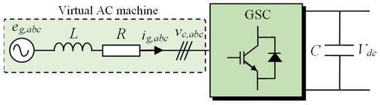
Figure 2.
Studied three-phase GSC.
By integrating (1), the VF estimation is obtained:
where ψg = [ψgα ψgβ]T is the virtual flux and v = vc + Rig represents the sum of the converter voltage and the resistive voltage drop.
The voltage drop across the resistance R is often small enough to be neglected. However, to maintain the general validity of the estimation method (e.g., for low-power converters), this resistance is considered.
Direct implementation of (2) via an ideal integrator faces two major practical challenges. First, DC offset components in the measured voltages and currents cause the integrator to drift and eventually saturate. Second, an inaccurate initialization of the flux estimate introduces a persistent offset at the integrator output, thereby degrading the estimation accuracy. To overcome these drawbacks, enhanced filtering structures can be employed. As illustrated in Figure 3, the SOGI can be configured as a band-pass filter (BPF) with a cutoff frequency equal to the grid frequency ω, which enables the simultaneous integration and filtering of the input voltage v. The corresponding transfer functions are expressed as
where ψ denotes the flux obtained by integrating the input voltage v, v′ is the filtered version of v, and is a tuning gain that determines the convergence speed of the SOGI [23].
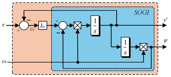
Figure 3.
Block diagram of a SOGI-based filter.
Although the SOGI provides satisfactory performance, it remains sensitive to DC offset and grid frequency deviations [23], thus requiring a frequency-locked loop that increases computational complexity [16,24]. To overcome these limitations, [13] proposed ANN-QSG for VF estimation within an MPDPC scheme. However, MPDPC still suffers from the drawback of a variable switching frequency, and the employed estimator, limited to two adaptive weights, cannot effectively compensate for voltage offset in the grid.
The following section introduces a ANN-QSG-based approach designed to mitigate these limitations.
2.2. Proposed ANN-QSG Estimator
To overcome the limitations of conventional estimators, particularly their poor robustness under grid disturbances such as unbalance, harmonics, and DC offsets, this work introduces a novel virtual-flux estimation method based on an ADALINE neural network configured as a quadrature signal generator. The structure employs three adaptive weights: one dedicated to the DC component to ensure intrinsic offset rejection, and two associated with the fundamental component to extract the in-phase and quadrature signals required for flux estimation. The following subsection presents the mathematical modeling of the proposed estimator.
First, the voltage vector v is modeled in the discrete-time domain using a Fourier-series expansion:
where V1, ω1, and φ1 are the amplitude, angular frequency, and initial phase of the fundamental component, respectively, while Vn, ωn, and φn denote those of the nth harmonic; Ts is the sampling period; and A and B represent the DC offsets of vα and vβ, respectively.
Unlike conventional filtering approaches that aim to reject the DC offset, the model at the core of the ANN-QSG is explicitly designed to identify and model both the fundamental and the DC components simultaneously. The model of the voltage to be estimated, for each axis α and β, is therefore defined by
Equation (5) can be written in the following more explicit form:
This model can be learned by an ANN with three weights, W = [w1 w2 w3], which are updated online to converge to the actual parameters X. The ANN-QSG structure, shown in Figure 4, uses as its input vector d (k) = [1 cos (ω1kTs) sin (ω1kTs)]T and updates its weights recursively via the least-mean-squares (LMS) algorithm [27]:
where , η is the learning rate, λ (k) = v (k) − v′ (k) is the voltage estimation error, and ε is a positive constant that prevents any division by zero.
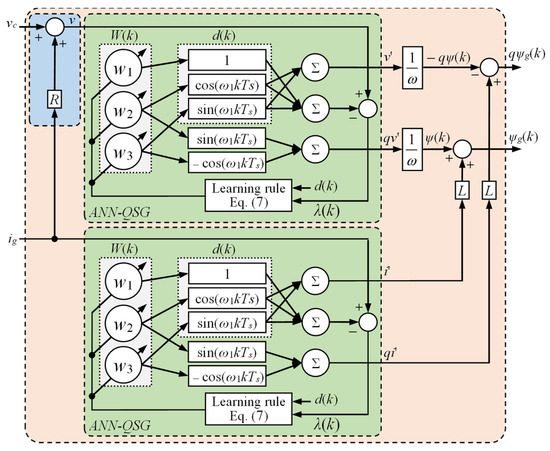
Figure 4.
ANN-QSG VF estimator.
A detailed analysis of the stability and selection criteria for the learning rate η is provided in [18]. In the proposed ANN-QSG, the weights are updated online using the LMS algorithm, where η is the only parameter to be tuned, since the method does not require offline training or initialization. According to Lyapunov’s convergence theory [18], the admissible range ensuring the stability of the ANN-QSG is
Beyond stability, η also affects convergence speed, accuracy, and harmonic rejection capability, thereby introducing a fundamental tradeoff. Small values of η enhance accuracy and harmonic attenuation but slow down convergence, whereas larger values accelerate convergence at the expense of accuracy, with possible oscillations and overshoots during transients. To balance these effects, η is initially set to a small value and subsequently adjusted based on the observed convergence speed and harmonic rejection performance.
Once convergence is achieved, the quadrature vector qv′ (k) = [qv′α (k) qv′β (k)]T, required for flux estimation, is synthesized from the adaptive weights w2 and w3, which represent exclusively the fundamental component, while the DC offset captured by w1 is neglected. Using trigonometric identities then yields
Given that the vector qv′ lags the vector v by a 90° phase angle, it is equivalent to the integral of v scaled by the angular frequency ω1. Therefore, the corresponding VF ψ′ for vector v can be derived as follows:
Consequently, the VF ψg corresponding to the grid voltages defined in (2) can be expressed as a function of ψ’ as follows:
The 90° phase-shifted virtual flux vector required for implementing the proposed control strategy can also be obtained from the direct output of the ANN-QSG. Indeed, one only needs to invert the sign of the direct output vector v′ (k), provided natively by the ANN-QSG, to generate the quadrature vector qψ (k) = −v′ (k). This inherent property of the ANN-QSG significantly simplifies the control implementation by eliminating any additional phase-shifting stage. The vector qψg can then be calculated as follows:
In parallel, a second ANN-QSG estimator is implemented for the grid current ig. It provides its filtered version, i’g (k), as well as its quadrature component, qi′g (k). The latter is utilized in (12) for the quadrature flux estimation.
Figure 4 illustrates the architecture of the VF estimator based on the ANN-QSG. The structure relies on a linear neuron with three adaptive weights, without prior initialization, updated online through the LMS algorithm (7). The network input vector d (k) = [1 cos (ω1kTs) sin (ω1kTs)]T captures both the DC and fundamental components.
To illustrate the appropriate selection of η, the obtained results for different values are presented in Figure 5, featuring a 50% voltage sag at t = 0.26 s, followed by an additive noise perturbation at t = 0.34 s and a 15% injection of the fifth- and seventh-order harmonics at t = 0.42 s. As shown in Figure 5a, the three-phase voltages in the αβ reference frame are sinusoidal before the disturbance and become distorted afterward, while Figure 5b depicts the estimated VF magnitude. A high learning rate (η = 0.008) yields fast but oscillatory dynamics, whereas a low value (η = 0.002) provides smooth but slow convergence. An intermediate rate (η = 0.004) achieves a suitable trade-off between speed and stability.
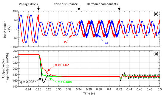
Figure 5.
ANN-QSG under input vector disturbance: (a) input vector v and (b) VF output vector magnitude.
The ANN-QSG provides, at its output, both a filtered and a quadrature version of the voltage and current signals, which are then used to reconstruct the VF components. In this configuration, the DC component is intrinsically rejected by the weight w1, while w2 and w3 extract the fundamental in-phase and quadrature components, respectively. Thus, the estimator replicates the behavior of an ideal integrator, free from drift and saturation, while exhibiting strong rejection capability against unbalance voltage, harmonics, and DC offset.
3. Predictive Control of the GSC
3.1. Conventional PDPC
In this section, the PDPC strategy is presented. It is based on the deadbeat principle, applied to a grid-connected PWM converter. Unlike conventional approaches, PDPC combines the advantages of a fast dynamic response, inherent to deadbeat control, with the maintenance of a fixed switching frequency. This feature allows for a simultaneous reduction in switching losses and harmonic distortions. The principle of PDPC is to determine, at each sampling step, the optimal voltage vector that minimizes the errors in active power P and reactive power Q at the next instant. This prediction is based on the converter model defined by (1). First, the instantaneous pq theory [28] is used to express the complex power S of the converter as follows:
The instantaneous active and reactive powers are then given by
Assuming that the grid voltages are sinusoidal and balanced, i.e., eg = |eg|ejωt, the time derivative of the complex power can be obtained as
The converter model, expressed in continuous time domain in terms of the complex power (16), is discretized over a sampling period Ts. The resulting discrete-time model allows for the calculation of the control vector from the powers and voltages measured at the sampling instant k. Several discretization techniques can be considered for this transformation. However, for a sufficiently small sampling period (here Ts = 10 μs), the first-order forward Euler method provides an accurate approximation of the continuous-time model [25].
The complex power in (17) must converge to its reference value at instant k + 1, expressed as
The change in apparent power between two successive sampling instants is given by
The analysis (19) allows for the determination of the matrix expression of the optimal control vector, expressed as
where Pref (k + 1) and Qref (k + 1) are the active- and reactive-power references for the next sampling period.
Deadbeat predictive control anticipates the system’s future state using the references Pref (k + 1) and Qref (k + 1) to compute directly the control vector that ensures optimal tracking at the next instant. This strategy is based on an analytical prediction that enforces immediate convergence of P (k + 1) and Q (k + 1) to their setpoints. This requires knowledge of the future references at instant k + 1. In many applications, the reactive-power reference remains constant, and often zero under unity power-factor operation. It is therefore common to approximate Qref (k + 1) ≈ Qref (k). In contrast, predicting the active-power reference Pref (k + 1), typically provided by the DC-bus voltage regulator, requires a more precise estimation. An extrapolation method, such as a Lagrange formula, is employed to estimate Pref (k + 1) more precisely:
Figure 6 illustrates the block diagram of the conventional PDPC strategy. In this study, the analysis focuses exclusively on active and reactive power regulation performance; the outer DC-bus voltage loop is therefore not detailed. The control law in (20) computes analytically the optimal voltage vector for regulation of P and Q under balanced-grid conditions. However, in the presence of voltage unbalance, this approach exhibits limitations in terms of dynamic response and robustness. To address these, an extension of the PDPC strategy is proposed in the following section.
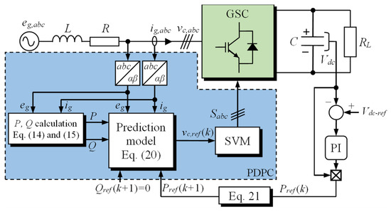
Figure 6.
Block diagram of the conventional PDPC scheme.
3.2. Proposed VF-PDPC
To address the limitations of the conventional PDPC strategy under voltage unbalance, this section introduces an enhanced method based on the extended instantaneous power theory commonly referred to as the extended pq theory. This formulation enables the analytical determination of the optimal control voltage vector even under unbalanced grid conditions. In a sensorless control framework, the VF concept is employed to eliminate direct grid voltage measurements, thereby simplifying implementation and reformulating the expression of the reactive power injected into the grid. By integrating the VF into the complex power expression, the resulting control scheme ensures both effective operation and improved robustness against grid disturbances.
The following step incorporates the VF into the complex power formulation, yielding a new analytical expression as a function of the flux.
Accordingly, the instantaneous active and reactive powers can be expressed as
Under unbalanced conditions, electrical quantities such as currents and fluxes can be decomposed into positive and negative sequence components as follows:
Substituting (25) and (26) into (23) and (24) yields:
The exponential terms in (27) and (28) are replaced by their equivalent trigonometric expressions:
After detailed expansion of (29) and (30), terms group into three characteristic components:
with
Here, denotes the dot product and the cross product. Equations (33) and (34) reveal that cross terms Pc = −Qc and Ps = −Qs represent the oscillatory components of the instantaneous active and reactive powers. Under ideal balanced grid conditions, these components are eliminated, thereby ensuring constant power transfer without fluctuations (P = P0 et Q = Q0).
In contrast, under unbalance the cross terms become nonzero, inducing double-frequency (2ω) oscillations in both P and Q.
In this study, the VF-PDPC control strategy is developed to ensure the generation of a perfectly sinusoidal current, even under grid disturbances or unbalances. To achieve this objective, it is necessary to cancel the oscillatory components of the active power by imposing the conditions Ps = Pc = 0. This constraint ensures a stable and regular waveform for the injected current. In return, the oscillatory components of the reactive power, Qs and Qc, are non-zero and therefore not controlled. To simplify their identification and analysis, the quadrature component of the VF, obtained from the proposed estimator, is utilized within the framework of the extended pq theory [19] to reconstruct the expressions for the reactive powers. Although the reactive power oscillations are not compensated, the use of the quadrature flux preserves high current quality while simplifying control implementation. In this context, and to facilitate the processing of reactive powers in the control, Equation (22) is modified by substituting the VF with its quadrature component, which yields the new expression for the complex power:
where .
Based on the previously described methodology, the expressions of the active and reactive powers can be formulated as follows:
The symmetry between the direct and quadrature components is exploited using the following transformation:
where x denotes either a current or a flux, and q indicates a 90-degree phase shift.
Applying the transformation introduced in (40) to (33) and (34) yields the following expressions:
where and .
Based on Equations (41) and (42), the mathematical formulation underlying the proposed control strategy is expressed as follows:
Considering Equations (43) and (44), and considering the simplifying assumptions presented in (45) and (46), the reference current can be calculated as follows:
After deriving the reference currents are obtained from (47), the active and reactive powers are recalculated to satisfy the conditions imposed by Equations (43)–(46), even under grid voltage unbalances or DC offset. This crucial step ensures accurate control of the power injected into the electrical grid. The resulting reference powers can be expressed as follows:
Finally, the optimal control vector of the VF-PDPC strategy is determined based on the reference power:
Figure 7 illustrates the complete functional architecture of the proposed VF-PDPC control strategy. This strategy estimates the VF using an adaptive neural network of the ADALINE type. The estimated VF is then employed to calculate active and reactive innovative power components, in accordance with the extended instantaneous power theory. Based on the discretized predictive model (50), the reference voltage vector is analytically determined and applied to the PWM converter. Unlike the conventional PDPC strategy, whose performance degrades under voltage unbalance conditions, the VF-PDPC method ensures stable and robust regulation, maintaining a perfectly sinusoidal injection current. Moreover, it guarantees unity power factor, thereby improving energy efficiency. Overall, this method offers an effective, robust, and high-performance solution for modern grid-connected power conversion systems.
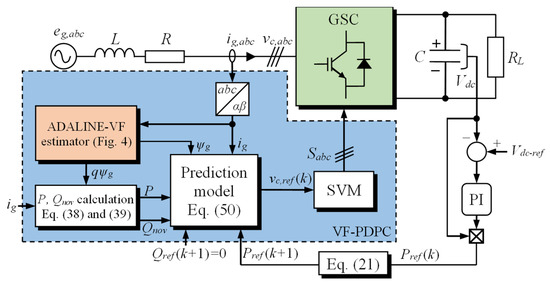
Figure 7.
Block diagram of the proposed VF-PDPC scheme.
4. Results
To validate the performance of the VF estimator and VF-PDPC control strategy, real-time simulation tests were performed on the OP4512 platform (see Figure 8). The hardware in the loop (HIL) methodology enables assessment of algorithm stability and robustness under quasi-real conditions, accounting for critical constraints like computational capacity, memory, and sampling time [29,30]. The sampling interval requires careful selection: shorter intervals improve accuracy but risk processor overload and numerical instability [31]. Hardware implementations must also address nonlinearities of power devices such as IGBTs [32].
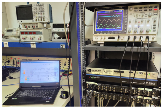
Figure 8.
Photograph of the OPAL-RT-based real-time system.
The model was developed in MATLAB/Simulink R2024b, optimized for RT-LAB, compiled and deployed on the OP4512. The controller and power model ran in real time on the platform CPU, with currents acquired via analog I/Os and estimated fluxes visualized on a GW Instek GDS-2204A oscilloscope. This setup enabled experimental validation of the efficiency of the VF estimator and VF-PDPC strategy. Finally, a comparative analysis was conducted to confirm the effectiveness of the proposed approach against the SOGI-based estimator [23] and the ANN-QSG-based VF estimator proposed in [13], while the VF-PDPC strategy was benchmarked against the conventional PDPC with a voltage sensor as well as a PDPC variant enhanced by the extended pq theory combined with a SOGI estimator. Operation under unity power factor was imposed by setting the reference reactive power to zero. The main system parameters used in these experiments are summarized in Table 1.

Table 1.
System parameters.
4.1. Comparison of VF Estimators
For the comparative study, the SOGI estimator gain was optimally tuned following the procedure in [23], while the learning rate η for both the proposed ANN-QSG estimator and the one from [13] was set to 0.004. Three tests were carried out. The first test evaluates the performance of the three estimators during startup under ideal conditions, without prior initialization. The second test is performed under grid-voltage distortion with 30% of the fifth and 10% of the seventh harmonics. The third test is conducted with grid voltages polluted by a 25% DC offset (20 V DC) of the nominal voltage component. Finally, the fourth test combines all grid disturbances simultaneously, including voltage unbalance, harmonic distortion, and DC offset, in order to assess the robustness of the estimators under the most critical operating conditions.
4.1.1. Startup Performance
Figure 9 illustrates a performance comparison of the VF estimators during startup, without prior initialization, comparing the SOGI estimator, the ANN-QSG proposed in [13] and the proposed ANN-QSG estimator.
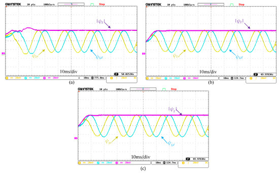
Figure 9.
Estimated VF ψg (200 Wb/div) during startup: (a) SOGI estimator, (b) ANN-QSG estimator [13] and (c) proposed ANN-QSG estimator.
According to Figure 9a, the SOGI estimator reaches 95% of its final value in approximately 25 ms, with a transient overshoot of about 18%, before settling at its nominal level. This behavior is due to the SOGI’s resonant structure, which, although effective for fundamental component extraction, exhibits insufficient damping, leading to a pronounced oscillatory response during initialization. Conversely, as shown in Figure 9b,c, the ANN-QSG proposed in [13] and the one proposed in this article converge in only 10 ms, without any significant overshoot. This enhanced performance is attributed to the ADALINE-type adaptive learning, which dynamically adjusts the weights in real time while effectively suppressing initial biases. These results demonstrate the transient superiority of both ANN-QSG estimators in terms of convergence speed and stability.
4.1.2. Harmonic Distortion
Figure 10 presents the comparative performance of the three estimators under grid-voltage distortion, including 30% of the fifth and 10% of the seventh harmonics. The results show that all three estimators significantly mitigate the impact of harmonic components on the estimated VF. Although the voltages are highly distorted, the SOGI estimator (Figure 10a), the ANN-QSG estimator [13] (Figure 10b), and the proposed ANN-QSG estimator (Figure 10c) accurately extract the fundamental component of the VF, denoted as ψg. The resulting waveforms remain nearly sinusoidal in all cases, with a total harmonic distortion (THD) of 6.52% for the SOGI estimator and 1.73% for both ANN-QSG estimators. These results confirm a high immunity to harmonic disturbances. Such strong harmonic-rejection capability is essential to maintain control-loop stability and ensure optimal performance in distorted grid environments.
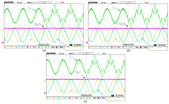
Figure 10.
Estimated VF ψg (200 Wb/div) for distorted grid voltages with 10% of 5th and 7th harmonics: (a) SOGI estimator, (b) ANN-QSG estimator [13] and (c) proposed ANN-QSG estimator.
4.1.3. DC Offset
Figure 11 shows the estimators’ performance under a 20 V DC offset (25.7% of the nominal grid voltage). The SOGI estimator (Figure 11a) exhibits an amplitude drift of about 5% of the nominal flux with pronounced oscillations due to resonance with the DC component, revealing its poor DC-rejection capability. Similarly, the ANN-QSG estimator in [13] (Figure 11b) suffers from a persistent DC bias in both flux components, leading to oscillations in the flux magnitude up to 30% of its initial value, as the model does not account for DC offset. In contrast, the proposed ANN-QSG estimator (Figure 11c) instantly eliminates the DC offset: the estimated flux remains centered at its nominal value, free of drift and oscillations. This robustness is achieved through ADALINE’s ability to simultaneously identify the DC component (w1) and the fundamental component (w2, w3), ensuring intrinsic DC-bias rejection.
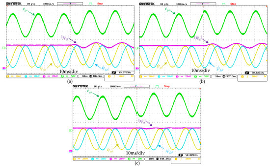
Figure 11.
Estimated VF ψg (200 Wb/div) with a 20 V DC offset in grid voltages: (a) SOGI estimator, (b) ANN-QSG estimator [13] and (c) proposed ANN-QSG estimator.
4.1.4. Unbalance, Harmonics and DC Offset
Figure 12 compares the three virtual-flux estimators (SOGI, ANN-QSG [13], and the proposed ANN-QSG) under severe disturbances, including a 30% voltage unbalance, fifth- and seventh-order harmonics, and a 20 V DC offset. SOGI exhibits significant waveform distortion and oscillations due to its sensitivity to unbalance and DC components. The ANN-QSG [13] provides improved flux quality but remains affected by the lack of DC offset compensation. In contrast, the proposed ANN-QSG demonstrates clear superiority: by introducing a third adaptive weight, it effectively eliminates the DC offset, rejects harmonics, and maintains a nearly sinusoidal flux waveform, with only minor oscillations attributed to the 30% unbalance.
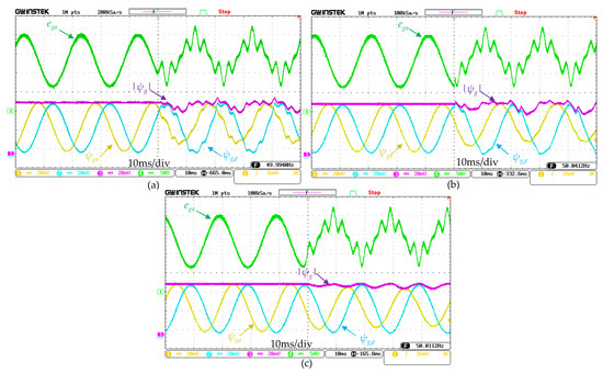
Figure 12.
Estimated VF ψg (200 Wb/div) under all grid voltage perturbation types: (a) SOGI estimator, (b) ANN-QSG estimator [13] and (c) proposed ANN-QSG estimator.
In order to highlight the effectiveness of the studied estimation methods, a comparative analysis was carried out under both ideal and disturbed grid conditions. The main performance criteria considered include the start-up dynamics, harmonic distortion, and sensitivity to DC offset. The obtained results are summarized in Table 2, which clearly shows the superiority of the proposed ANN-QSG estimator compared to conventional SOGI and ANN-QSG methods, particularly in terms of start-up response and robustness against distortions.
Table 2.
Comparative summary of the performance of the studied virtual-flux estimators.
4.2. Comparison Results of Control Techniques
To evaluate the performance of the VF-PDPC control, a comparison is made with conventional PDPC and with the pq theory-based PDPC strategy. The three control methods are implemented under the same conditions, using the parameters presented in Table 1. During all tests, the reactive power reference Qref is set to zero, thus ensuring unity power factor operation. The outer DC-bus voltage controller is disabled to focus on the inner control loop. Therefore, the active-power reference Pref = 500 W is externally imposed.
4.2.1. Comparison Under Unbalanced Grid Conditions
The results in Figure 13 are obtained for an initially balanced, purely sinusoidal grid voltage, followed by a 30% drop in phase-a voltage.
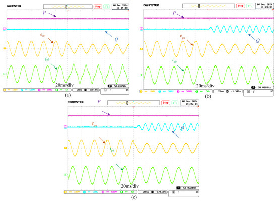
Figure 13.
Grid voltage ega (100 V/div), grid current igb (10 A/div), active power P (500 W/div), and reactive power Q (500 VAr/div) for unbalanced grid voltages: (a) conventional PDPC, (b) pq theory-based PDPC, and (c) proposed VF-PDPC.
Under balanced conditions, all three strategies produce near-sinusoidal grid currents. This validates that the use of the extended pq theory in the proposed approach does not degrade performance under ideal conditions compared to the conventional pq theory. When the unbalance is applied, the conventional PDPC (Figure 13a) fails to maintain current waveform quality: the current becomes highly distorted, reaching a total harmonic distortion (THD) of 14.26%, well above the 5% limit recommended by the institute of electrical and electronics engineers (IEEE) standard for harmonic control in electric power systems (IEEE std 519-2022) [33]. Conversely, both approaches based on the extended pq theory, namely the reference PDPC [19] (Figure 13b) and the proposed VF-PDPC (Figure 13c), maintain near-sinusoidal currents with respective THDs of 1.41% and 1.44%. The reactive-power oscillations observed are inherent to the extended pq formulation, which prioritizes the quality of the injected current. These results show that VF-PDPC achieves performance equivalent to extended pq theory-based PDPC while requiring a reduced number of sensors.
4.2.2. Comparison Under an Unbalanced and Distorted Grid Conditions
For the results in Figure 14, the grid voltages are initially purely sinusoidal and balanced, then a 30% sag is applied to the phase-a voltage, and all three grid voltages are polluted by fifth- and seventh-order harmonic components (10% of the fifth and 10% of the seventh harmonics).
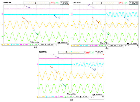
Figure 14.
Grid voltage ega (100 V/div), grid current igb (10 A/div), active power P (500 W/div), and reactive power Q (500 VAr/div) for unbalanced and distorted grid voltages: (a) conventional PDPC, (b) pq theory-based PDPC, and (c) proposed VF-PDPC.
Figure 14a shows that the conventional PDPC maintains stable P and Q but yields heavily distorted three-phase currents (THD = 27.87%), demonstrating its inability to filter or compensate harmonics. Similarly, the PDPC based on the extended pq theory (Figure 14b) also fails to improve the current quality, as this approach does not account for harmonic components; the current waveforms remain significantly distorted with a THD of 18.27%. In contrast, the proposed VF-PDPC strategy (Figure 14c) combines the VF estimator to effectively mitigate harmonics with the extended pq theory to manage the grid unbalance. The result is a sinusoidal current waveform (THD = 2.29%) with constant, ripple-free active power. This performance demonstrates the superiority of the proposed method, which simultaneously ensures precise active power tracking and excellent current quality under both unbalance and harmonic distortion.
4.2.3. Robustness Evaluation of the VF-PDPC
This test aims to evaluate the robustness of the proposed control strategy when subjected to highly degraded grid conditions. The main objective is to assess its ability to maintain both the quality and the sinusoidal shape of the injected current, as well as the stability of the active power without oscillations, even in the presence of severe disturbances affecting the grid voltage.
To this end, a first test is performed by applying a series of successive faults to the grid voltages, as illustrated in Figure 15a. To further strengthen this analysis, a 300 W step variation is subsequently imposed on the active power while keeping the grid under severe conditions, as shown in Figure 15b. In the first scenario, the faults are introduced sequentially while the active power reference is kept constant. These faults include a 20V DC offset (25.7% of the nominal voltage), a 30% voltage sag on phase a, and a 10% harmonic distortion introduced by the fifth- and seventh-order components. Figure 14a demonstrates that, despite these disturbances, the grid current maintains a sinusoidal waveform and the active power remains constant. However, significant oscillations can be observed in the reactive power.
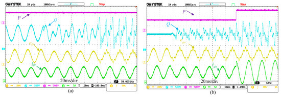
Figure 15.
Grid voltage ega (100 V/div), grid current igb (10 A/div), active power P (500 W/div), and reactive power Q (500 VAr/div) during (a) default integration and (b) a step change in active power.
In the transient scenario depicted in Figure 15b, the VF-PDPC strategy exhibits an extremely fast dynamic response. The active power (P) instantaneously tracks the new reference without overshoot, highlighting the effectiveness of the deadbeat predictor combined with the VF estimator. At the same time, the grid current (igb) immediately adjusts its amplitude to match the increased active power demand while preserving a nearly sinusoidal waveform (THD = 3.32%). These results confirm that the ANN-QSG effectively filters harmonics, even during transient operation.
The absence of overshoot, combined with the preserved current quality and stable active power, validates the capability of the VF-PDPC strategy to follow abrupt setpoint variations without compromising either stability or waveform quality, even under severely degraded grid conditions.
To further evaluate the robustness and limitations of the studied control strategies, a comparative analysis of the PDPC methods was carried out for different fault levels injected into the grid voltages, including voltage unbalance, harmonic distortion, and DC offset. The performance evaluation was based on the current quality at the PCC and the system’s ability to suppress oscillations. The obtained results, illustrated in Figure 16 and summarized in Table 3, demonstrate the superior performance of the proposed VF-PDPC method in mitigating distortion and ensuring a stable, oscillation-free response compared to conventional PDPC approaches. As shown in Figure 16a, the proposed VF-PDPC achieves a significant reduction in current THD across all harmonic orders, whereas the conventional PDPC and the pq-based PDPC exhibit a steady increase in distortion with higher harmonic penetration. Under voltage unbalance conditions, illustrated in Figure 16b,c, the conventional PDPC results in severe deterioration of current quality, with THD values exceeding 12% for unbalance levels above 25%. In contrast, the proposed VF-PDPC maintains nearly sinusoidal currents with THD values below 0.05%, as highlighted in the insets of Figure 16b,c. The extended pq theory-based PDPC also preserves satisfactory performance under unbalance but still underperforms compared to the proposed method. Therefore, the VF-PDPC can be regarded as a promising solution for next-generation grid-connected converters, as it ensures superior current quality, robust mitigation of distortion, and stable operation even under weak, unbalanced, or highly distorted network conditions.
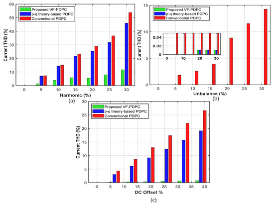
Figure 16.
Current THD of the studied control strategies under grid disturbances: (a) 5th and 7th harmonic distortions, (b) type-A voltage sag, and (c) DC offset.
Table 3.
Comparative summary of the performance of the studied PDPC methods under critical grid conditions.
The execution time results show that the proposed VF-PDPC requires slightly more computational effort compared to the conventional PDPC and the PQ-theory PDPC under ideal grid conditions (5.5 µs versus 3.8 µs and 4.3 µs, respectively). This increase is expected, since the proposed method integrates the ANN-QSG estimator together with the extended pq-theory formulation, which introduce additional calculations. However, the obtained execution time of 5.5 µs remains significantly lower than the sampling period (Ts = 10 µs), thus ensuring real-time feasibility on the digital controller. Moreover, this marginal overhead is fully justified by the improved robustness against DC offset, harmonics, and unbalances provided by the proposed VF-PDPC approach.
5. Conclusions
In this work, a virtual flux estimator based on the ADALINE neural network was designed and integrated into a sensorless direct predictive power control strategy. Simulation results, complemented by real-time validation on the OP4512 OPAL-RT platform, confirmed the accuracy and robustness of the proposed approach. The estimation converges within less than 8 ms with an error below 2%, while maintaining current THD below 3% even under unbalanced and heavily distorted grid conditions. Compared to conventional predictive control relying on direct voltage measurements, the VF-PDPC strategy reduces hardware complexity, eliminates the need for voltage sensors, and enhances overall system reliability. Furthermore, comparative studies demonstrated that the proposed ANN-QSG estimator outperforms the conventional SOGI in terms of accuracy and robustness, while the VF-PDPC achieves superior power regulation and current quality compared to conventional and extended pq-based PDPC methods. Overall, the proposed approach constitutes a significant advancement in sensorless predictive control of grid-connected converters operating under challenging conditions, delivering a robust, efficient, and practical solution with direct relevance to industrial systems, smart grid infrastructures, and renewable energy.
Author Contributions
Conceptualization, N.A. and A.R.; methodology, B.B., A.R., K.M. and A.S.; software, N.A., A.R. and K.M.; investigation, N.A., B.B., A.R., A.H. and K.M.; resources, A.S.; writing, B.B., A.R. and K.M.; writing—review, B.B., A.S. and A.H.; supervision, B.B. All authors have read and agreed to the published version of the manuscript.
Funding
This research received no external funding.
Data Availability Statement
The data are available on request from the corresponding author.
Conflicts of Interest
The authors declare no conflicts of interest.
Abbreviations
| Symbols | |
| vc | Converter voltage vector |
| eg | Grid voltage vector |
| ig | Grid current vector |
| ψg | Grid virtual flux vector |
| qψ | Quadrature component of the virtual flux |
| i′g, qi′g | Filtered and quadrature components of the grid current |
| R, L | Grid filter resistance and inductance |
| Ts | Sampling period |
| ω1 | Fundamental angular frequency of the grid |
| V1, ϕ1 | Amplitude and phase of the fundamental component |
| Vn, ωn, ϕn | Amplitude, angular frequency, and phase of the n-th harmonic |
| A,B | DC components (offsets) |
| d(k) | Input vector of the ANN-QSG |
| W | Adaptive weights of the ADALINE |
| η | Learning rate of the LMS algorithm |
| λ(k) | Voltage estimation error |
| S | Instantaneous complex power |
| P, Q | Instantaneous active and reactive powers |
| Pref, Qref | Active and reactive power references |
| Pc, Ps | Oscillatory components of the active power |
| Qc, Qs | Oscillatory components of the reactive power |
| Abbreviations | |
| ADALINE | Adaptive linear neuron |
| ANN | Adaptive neural network |
| ANN-QSG | Adaptive neural network-based quadrature signal generator |
| BPF | Band-pass filter |
| GSC | Grid-side converter |
| LPF | Low-pass filter |
| LMS | Least-mean-squares |
| MPDPC | Model predictive direct power control |
| PDPC | Predictive direct power control |
| PLL | Phased-locked loop |
| PWM | Pulse width modulation |
| SOGI | Second-order generalized integrator |
| SVM | Space vector modulation |
| THD | Total harmonic distortion |
| VF | Virtual flux |
References
- Boukais, B.; Mesbah, K.; Rahoui, A.; Saim, A.; Houari, A.; Benkhoris, M.F. Development of a 3 kW Wind Energy Conversion System Emulator Using a Grid-Connected Doubly-Fed Induction Generator. Actuators 2024, 13, 487. [Google Scholar] [CrossRef]
- Yang, S.; Wang, R.; Zhou, J.; Chen, B. Intermediate-Variable-Based Distributed Fusion Estimation for Wind Turbine Systems. Actuators 2022, 11, 15. [Google Scholar] [CrossRef]
- Rajendran, S.; Diaz, M.; Devi, V.S.K.; Jena, D.; Travieso, J.C.; Rodriguez, J. Wind Turbine Emulators—A Review. Processes 2023, 11, 747. [Google Scholar] [CrossRef]
- Tasnim, M.N.; Ahmed, T.; Dorothi, M.A.; Ahmad, S.; Shafiullah, G.M.; Ferdous, S.M.; Mekhilef, S. Voltage-Oriented Control-Based Three-Phase, Three-Leg Bidirectional AC–DC Converter with Improved Power Quality for Microgrids. Energies 2023, 16, 6188. [Google Scholar] [CrossRef]
- Lee, S.S.; Heng, Y.E. Optimal VF-PDPC of Grid Connected Inverter Under Unbalanced and Distorted Grid Voltages. Electric Power Syst. Res. 2016, 140, 1–8. [Google Scholar] [CrossRef]
- Ma, H.; Yao, X.; Wang, J.; Luo, X.; Huang, S. Improved Deadbeat Predictive Direct Power Control for Three-Phase PWM Rectifier Based on LADRC. J. Mar. Sci. Eng. 2025, 13, 402. [Google Scholar] [CrossRef]
- Tao, Y.; Wu, Q.; Wang, L.; Tang, W. Voltage Sensorless Predictive Direct Power Control of Three-Phase PWM Converters. IET Power Electron. 2016, 9, 1009–1018. [Google Scholar] [CrossRef]
- Jabbarnejad, A.; Vaez-Zadeh, S.; Jahanpour-Dehkordi, M. Combined Control of Grid Connected Converters Based on a Flexible Switching Table for Fast Dynamic and Reduced Harmonics. IEEE Trans. Energy Convers. 2020, 35, 77–84. [Google Scholar] [CrossRef]
- Bouafia, A.; Krim, F.; Gaubert, J.-P. Fuzzy-Logic-Based Switching State Selection for Direct Power Control of Three-Phase PWM Rectifier. IEEE Trans. Ind. Electron. 2009, 56, 1984–1992. [Google Scholar] [CrossRef]
- Ahmad, S.; Mekhilef, S.; Mokhlis, H.; Karimi, M.; Pourdaryaei, A.; Ahmed, T.; Jhuma, U.K.; Afzal, S. Fuzzy Logic-Based Direct Power Control Method for PV Inverter of Grid-Tied AC Microgrid Without Phase-Locked Loop. Electronics 2021, 10, 3095. [Google Scholar] [CrossRef]
- Malinowski, M.; Jasinski, M.; Kazmierkowski, M.P. Simple Direct Power Control of Three-Phase PWM Rectifier Using Space-Vector Modulation (DPC-SVM). IEEE Trans. Ind. Electron. 2004, 51, 447–454. [Google Scholar] [CrossRef]
- Nguyen, M.H.; Kwak, S.; Choi, S. Voltage Injection Based MPDPC Technique for Individual Phase Loss Reduction in Active Front-End Rectifier. IEEE Access 2024, 12, 51193–51207. [Google Scholar] [CrossRef]
- Rahoui, A.; Mesbah, K.; Boukais, B.; Amoura, N.; Saim, A.; Houari, A. Simplified Sensorless Predictive Control of Grid-Side Converter in Wind Energy Conversion Systems Under Distorted Grid Conditions. Energy Rep. 2025, 14, 1156–1168. [Google Scholar] [CrossRef]
- Rath, A.; Srungavarapu, G. Reduced Complexity Model Predictive Direct Power Control for Unbalanced Grid. Electr. Power Syst. Res. 2024, 234, 110563. [Google Scholar] [CrossRef]
- Amoura, N.; Rahoui, A.; Boukais, B.; Mesbah, K. Neural Networks-Based Adaptive Predictive Current Control of a Grid-Connected Three-Phase PWM Converter. In Proceedings of the 2024 2nd International Conference on Electrical Engineering and Automatic Control (ICEEAC), Setif, Algeria, 12–14 May 2024; pp. 1–6. [Google Scholar]
- Rahoui, A.; Mesbah, K.; Boukais, B.; Otmane-Cherif, T. Frequency-Adaptive Neural Network Based Virtual Flux Estimation for Sensorless Control of PWM Converters Under Unbalanced Conditions. In Proceedings of the 2020 International Conference on Electrical Engineering (ICEE), Istanbul, Turkey, 25–27 September 2020; pp. 1–6. [Google Scholar]
- Bouafia, A.; Gaubert, J.-P.; Krim, F. Predictive Direct Power Control of Three-Phase Pulsewidth Modulation (PWM) Rectifier Using Space-Vector Modulation (SVM). IEEE Trans. Power Electron. 2010, 25, 228–236. [Google Scholar] [CrossRef]
- Mesbah, K.; Rahoui, A.; Boukais, B. Neural Network Quadrature Signal Generator-Based Virtual Flux Estimation for Predictive Control of PWM Converters. IEEE Trans. Ind. Electron. 2024, 71, 4785–4794. [Google Scholar] [CrossRef]
- Zhang, Y.; Qu, C. Direct Power Control of a Pulse Width Modulation Rectifier Using Space Vector Modulation Under Unbalanced Grid Voltages. IEEE Trans. Power Electron. 2015, 30, 5892–5901. [Google Scholar] [CrossRef]
- Yang, H.; Zhang, Y.; Liang, J.; Liu, J.; Zhang, N.; Walker, P.D. Robust Deadbeat Predictive Power Control with a Discrete-Time Disturbance Observer for PWM Rectifiers Under Unbalanced Grid Conditions. IEEE Trans. Power Electron. 2019, 34, 287–300. [Google Scholar] [CrossRef]
- Malinowski, M.; Kazmierkowski, M.P.; Hansen, S.; Blaabjerg, F.; Marques, G.D. Virtual-Flux-Based Direct Power Control of Three-Phase PWM Rectifiers. IEEE Trans. Ind. Appl. 2001, 37, 1019–1027. [Google Scholar] [CrossRef]
- Norniella, J.G.; Cano, J.M.; Orcajo, G.A.; Rojas, C.H.; Pedrayes, J.F.; Cabanas, M.F.; Melero, M.G. Melero Improving the Dynamics of Virtual-Flux-Based Control of Three-Phase Active Rectifiers. IEEE Trans. Ind. Electron. 2014, 61, 177–187. [Google Scholar] [CrossRef]
- Ketzer, M.B.; Jacobina, C.B. Jacobina Virtual Flux Sensorless Control for Shunt Active Power Filters with Quasi-Resonant Compensators. IEEE Trans. Power Electron. 2016, 31, 4818–4830. [Google Scholar] [CrossRef]
- Roslan, N.F.; Luna, A.; Rocabert, J.; Candela, J.I.; Rodriguez, P. Remote Power Control Injection of Grid-Connected Power Converters Based on Virtual Flux. Energies 2018, 11, 488. [Google Scholar] [CrossRef]
- Zhang, Z.; Xu, H.; Xue, M.; Chen, Z.; Sun, T.; Kennel, R.; Hackl, C.M. Hackl Predictive Control with Novel Virtual-Flux Estimation for Back-to-Back Power Converters. IEEE Trans. Ind. Electron. 2015, 62, 2823–2834. [Google Scholar] [CrossRef]
- Sun, Y.; Li, Z.; Zhang, Y.; Li, Y.; Zhang, Z. A Time-Domain Virtual-Flux Based Predictive Control of Modular Multilevel Converters for Offshore Wind Energy Integration. IEEE Trans. Energy Convers. 2022, 37, 1803–1814. [Google Scholar] [CrossRef]
- Rahoui, A.; Boukais, B.; Mesbah, K.; Otmane-Cherif, T. Neural Networks Based Frequency-Locked Loop for Grid Synchronization Under Unbalanced and Distorted Conditions. In Proceedings of the 2020 International Conference on Electrical Engineering (ICEE), Istanbul, Turkey, 25–27 September 2020; pp. 1–6. [Google Scholar]
- Akagi, H.; Watanabe, E.H.; Aredes, M. Instantaneous Power Theory and Applications to Power Conditioning; John Wiley & Sons: Hoboken, NJ, USA, 2017; ISBN 978-1-118-36210-5. [Google Scholar]
- Buraimoh, E.; Davidson, I.E. Laboratory Procedure for Real-Time Simulation Experiment of Renewable Energy Systems on OPAL-RT Digital Simulator. In Proceedings of the 2022 10th International Conference on Smart Grid (icSmartGrid), Istanbul, Turkey, 27–29 June 2022; pp. 221–226. [Google Scholar]
- Golestan, S.; Golmohamadi, H.; Sinha, R.; Iov, F.; Bak-Jensen, B. Real-Time Simulation and Hardware-in-the-Loop Testing Based on OPAL-RT ePHASORSIM: A Review of Recent Advances and a Simple Validation in EV Charging Management Systems. Energies 2024, 17, 4893. [Google Scholar] [CrossRef]
- OPAL-RT Technologies, Inc. OP4512|Compact Entry-Level Real-Time Simulator for RCP and HIL Testing. OPAL-RT. Available online: https://www.opal-rt.com/hardware/simulators/real-time-simulators/op4512/ (accessed on 2 September 2025).
- Flack, C.; Ucer, E.; Smith, C.P.; Kisacikoglu, M. Controller Hardware-in-the-Loop (C-HIL) Testing of Decentralized EV-Grid Integration. In Proceedings of the 2022 IEEE Power & Energy Society General Meeting (PESGM), Denver, CO, USA, 17–21 July 2022; pp. 1–5. [Google Scholar]
- IEEE Std 519-2022 (Revision of IEEE Std 519-2014); IEEE Standard for Harmonic Control in Electric Power Systems. IEEE: New York, NY, USA, 2022; pp. 1–31. [CrossRef]


Disclaimer/Publisher’s Note: The statements, opinions and data contained in all publications are solely those of the individual author(s) and contributor(s) and not of MDPI and/or the editor(s). MDPI and/or the editor(s) disclaim responsibility for any injury to people or property resulting from any ideas, methods, instructions or products referred to in the content. |
© 2025 by the authors. Licensee MDPI, Basel, Switzerland. This article is an open access article distributed under the terms and conditions of the Creative Commons Attribution (CC BY) license (https://creativecommons.org/licenses/by/4.0/).