Article

Disturbance-Free Switching Control Strategy for Grid-Following/Grid-Forming Modes of Energy Storage Converters

1
China Nuclear Power Engineering Co., Ltd., Beijing 100840, China
2
Department of Electric Power Engineering, North China Electric Power University, Baoding 071003, China
*
Author to whom correspondence should be addressed.
Electronics 2025, 14(19), 3963; https://doi.org/10.3390/electronics14193963
Submission received: 2 September 2025 / Revised: 3 October 2025 / Accepted: 3 October 2025 / Published: 9 October 2025

Abstract

To address the problem of transient disturbance arising during the grid-following (GFL) and grid-forming (GFM) mode switching of energy storage converters, this paper proposes a dual-mode seamless switching control strategy. First, we conduct an in-depth analysis of the mechanism behind switching transients, identifying that sudden changes in current commands and angle-control misalignment are the key factors triggering oscillations in system power and voltage frequency. To overcome this, we design a virtual synchronous generator (VSG) control angle-tracking technique based on the construction of triangular functions, which effectively eliminates the influence of periodic phase-angle jumps on tracking accuracy and achieves precise pre-synchronization of the microgrid phase in GFM mode. Additionally, we employ a current-command seamless switching technique involving real-time latching and synchronization of the inner-loop current references between the two modes, ensuring continuity of control commands at the switching instant. The simulation and hardware-in-the-loop (HIL) experimental results show that the proposed strategy does not require retuning of the parameters after switching, greatly suppresses voltage and frequency fluctuations during mode transition, and achieves smooth, rapid, seamless switching between the GFL and GFM modes of the energy storage converter, thereby improving the stability of microgrid operation.

1. Introduction

In small-capacity AC microgrids, the use of a single control strategy—either grid-following (GFL) [1,2,3] or grid-forming (GFM) [4,5,6,7]—often fails to fully meet the composite demands of system stability [8,9,10] and operational support across multiple scenarios. GFL converters, which rely on phase-locked loop (PLL) synchronization [1,2], provide accurate power control but cannot autonomously regulate voltage and frequency [3]. In contrast, GFM converters, such as those employing Virtual Synchronous Generator (VSG) technology [4,5], can self-establish voltage and frequency, thereby enhancing system inertia, though their dynamic response may be comparatively slower under certain conditions [6,7]. To address these complementary characteristics, GFL/GFM dual-mode converters [10,11,12] have attracted increasing research attention due to their ability to combine operational robustness with dynamic performance. However, such dual-mode systems remain susceptible to transient disturbances during mode switching, which can severely compromise microgrid stability [13,14]. It is therefore essential to analyze the underlying transient mechanisms and develop effective suppression strategies to achieve a smoother switching process.
Various dual-mode switching schemes have been proposed in the literature, typically categorized into switching-based and fusion-based approaches. For example, several studies [15,16] adopt switching-type architectures with independent GFL and GFM controllers, focusing on seamless transitions by maintaining input signal consistency. Others [17] employ fusion-type designs that integrate features of both modes within a single control framework, though often at the cost of structural complexity and limited adaptability. Despite these contributions, the transient impact caused by mode switching remains particularly acute in low-inertia, small-capacity microgrids, posing a critical barrier to their widespread engineering application [18]. To reduce disturbances caused by switching, existing studies primarily focus on two directions: control-structure continuity and state tracking. Several methods have been validated through experimental prototypes or industrial tests. For instance, ref. [19] adopts a state-following strategy with current soft-start mechanism that has been tested on real benches to suppress bus voltage oscillations; refs. [20]’s closed-loop tracking approach for smooth connection between operational modes has been verified in laboratory conditions; while [21,22]’s VSG-based parameter presetting method has demonstrated effectiveness in practical applications.
These approaches present distinctive advantages: instantaneous value inheritance methods [23,24] excel in maintaining signal consistency, state-tracking strategies [19] offer robust transient performance, and VSG-based designs [21,22] provide inherent synchronization capabilities. A hybrid approach combining these strengths could potentially address phase jump issues while maintaining structural simplicity.
The effectiveness of existing methods varies significantly under different network conditions. In strong grids, state-tracking methods demonstrate excellent performance, whereas in weak grids with harmonic distortions, VSG-based approaches show better resilience to impedance variations. However, most methods face challenges in maintaining stability under concurrent noise and harmonic conditions, particularly during multiple consecutive switching events.
In summary, existing dual-mode control strategies can be divided into switching-type and fusion-type categories: the former designs grid-following and grid-forming controllers independently, achieving disturbance-free switching by keeping shared input signals unchanged, but struggling with phase jump issues; the latter fuses characteristics of both modes, typically requiring controller retuning, resulting in complex structures with limited adaptability to varying grid conditions.
In view of the limitations of existing research, such as reliance on parameter retuning, vulnerability to phase jumps, and complex control structures, this paper proposes a novel disturbance-free switching control strategy for grid-following/grid-forming modes, offering the following main innovations:
(1)
A Novel Constructed-Function-Based VSG Angle-Tracking Technique for Enhanced Synchronization Precision.
Unlike conventional Phase-Locked Loop (PLL) or PI-based tracking schemes that suffer from periodic disturbances and prolonged adjustment times due to the inherent 2π phase jumps, we propose a groundbreaking angle-tracking method utilizing a constructed trigonometric function. This innovative approach seamlessly transforms the periodically jumping phase-angle difference into a smooth, monotonic regulation signal. Consequently, it completely eliminates the reverse-regulation effect caused by phase transitions, achieving rapid and accurate pre-synchronization for GFM mode without any steady-state error. This represents a fundamental improvement in synchronization quality, ensuring a seamless transition at the moment of mode switching.
(2)
A Dual-Channel, State-Latching Architecture for Holistic Disturbance Suppression.
Moving beyond isolated solutions that address only current or angle disturbances, we establish a unified disturbance-free switching architecture that synchronously manages both the current reference and the control angle channels. The core of this architecture lies in its real-time latching and initialization mechanism. Specifically, the inner-loop current references between the two modes are latched and synchronized at the switching instant, while the integrator states of the outer-loop controllers are strategically reset. This coordinated approach guarantees the inherent continuity of all critical control commands, effectively suppressing the two primary sources of switching transients at their root.
(3)
A Non-Intrusive, Communication-Free Strategy for Enhanced Robustness and Practical Deployment.
A significant engineering advantage of our proposed strategy is its exclusive reliance on local measurement signals and inherent control states. It eliminates any dependency on external communication networks or real-time grid strength assessment, which are often impractical or costly in real-world applications. This inherent simplicity grants the strategy superior adaptability and robustness across diverse grid scenarios, from strong to weak grids. Therefore, it presents a high-performance, plug-and-play solution that is readily translatable from simulation to practical engineering applications without additional implementation complexity.
In practical microgrid and energy storage systems, the transition between grid-following (GFL) and grid-forming (GFM) modes is typically triggered by the following scenarios:
(1)
Intentional Islanding: The system deliberately switches from GFL to GFM mode to form an islanded network and continue supplying power to local critical loads when the main grid requires scheduled maintenance or experiences power quality issues.
(2)
Fault Ride-Through and Recovery: Upon a main grid fault, the system must switch to GFM mode to maintain its own stability. After the grid fault is cleared, it must resynchronize and switch back to GFL mode.
(3)
Grid Support Services: The system operates in GFM mode to provide active and reactive power support for grid voltage and frequency regulation upon dispatch commands, reverting to GFL mode after the task is completed.
The disturbance-free switching strategy proposed in this paper is designed specifically to address the power oscillations caused by control mode transitions in the aforementioned scenarios.

2. Grid-Following/Grid-Forming Converter Modeling and Analysis of Switching Disturbance Mechanism

2.1. Dual-Mode Converter System Architecture

2.1.1. Topology of Main Circuit

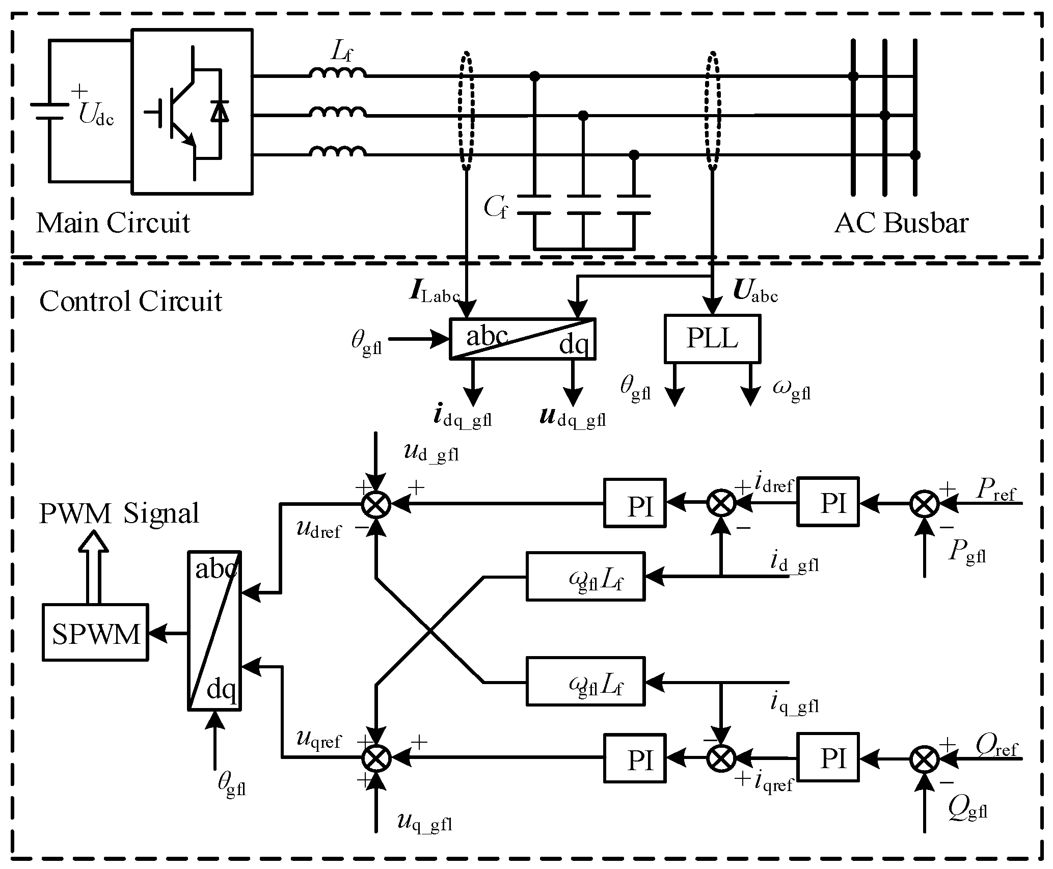
The main circuit of the energy storage converter is shown in Figure 1. The energy storage converter is connected to the AC microgrid through an LC filter.

2.1.2. Grid-Following-Type Control Strategy

The grid-following energy storage converter is based on phase-locked loop (PLL) control, and its output voltage and frequency are strictly synchronized with the grid; it cannot independently establish voltage and frequency. A block diagram of this type of converter is shown in Figure 2, and its control structure is implemented following the classical methodology described in reference [6].

2.1.3. Grid-Forming-Type Control Strategy

The grid-forming energy storage converter, by emulating the control characteristics of a synchronous generator, can achieve voltage phase self-synchronization without a phase-locked loop and can independently establish voltage and frequency. The grid-forming control strategy used in this study is VSG technology. A block diagram of this type of converter is shown in Figure 3, which illustrates the core VSG control algorithm as presented in reference [6].

2.2. Mode-Switching Principle and Disturbance-Free Switching Condition

To simplify the analysis and focus on the core mechanism of switching transients, the following idealizing assumptions are made in this section: the microgrid voltage is considered stable and constant, and the line impedance is neglected. Under these assumptions, the energy storage converter with a grid-following/grid-forming dual-mode-switching control circuit can be divided into common and independent control parts, as shown in Figure 4. The input to the common control part is provided by the independent control part, and its magnitude will vary as the converter control mode switches. The energy storage converter with a grid-following/grid-forming dual-mode-switching control circuit can be divided into common and independent control parts, as shown in Figure 4. The input to the common control part is provided by the independent control part, and its magnitude will vary as the converter control mode switches.
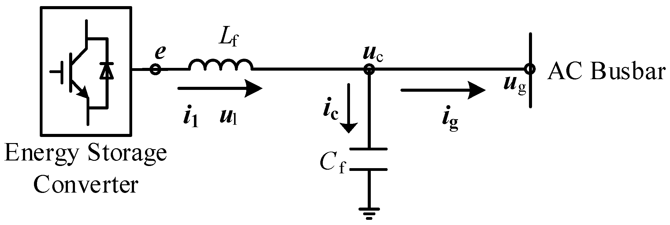
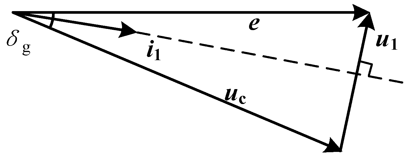
The grid-connected energy storage converter system is shown in Figure 5. The three vectors—the output voltage vector e, the LC filter inductive voltage vector ul, and the filter capacitive voltage vector uc—collectively form a voltage vector triangle, as shown in Figure 6.
To achieve disturbance-free switching of the energy storage converter between grid-following and grid-forming modes, the voltage vector triangle must remain unchanged during the transition. Since the change in the voltage vector uc depends on the grid-interactive microgrid voltage vector ug, when the microgrid is stable, uc can be considered unchanged. The output voltage vector e of the converter is determined by the control signal, and its variation depends on whether the input signal to the common control part changes. Therefore, to achieve disturbance-free switching, the key is to keep the input signal to the common control part unchanged.
In the dual-mode-switching control circuit, the common control part is the current inner loop, and dual-mode switching means the switching of input signals such as the d-axis current reference idref, the q-axis current reference iqref, and the control angle θc. Therefore, the conditions for disturbance-free switching are that the input signals to the current inner loop remain unchanged, and the microgrid voltage vector ug remains constant, so that the converter output voltage vector e remains unchanged, enabling disturbance-free switching between the two operation modes.

2.3. Analysis of the Mechanism of Transient Disturbances During Switching

During converter mode switching, transient disturbances are generated. In an AC microgrid, regardless of whether the converter operates in grid-following or grid-forming mode, the control objective is to regulate the converter’s active and reactive power outputs. Therefore, our primary analysis focuses on the impact of switching disturbances on the converter’s output power.
Let the AC microgrid voltage angle be θg. Before mode switching, the energy storage converter operates in grid-forming mode, where the converter output voltage angle is θc. Then, the phase-angle difference between the converter output voltage and the microgrid voltage is
δ g = θ c θ g
Since the converter is in grid-forming mode at this time and is responsible for supporting the voltage of the entire microgrid, the direction of the voltage vector e is defined along the d-axis, and the microgrid voltage vector magnitude is Ug. Therefore, the components of the microgrid voltage along the d and q axes are
u gd = U g cos δ g u gq = U g sin δ g
Ignoring line impedance, it can be assumed that the filter capacitor voltage vector uc is equal to the AC microgrid voltage vector ug. The KVL equation for the filter inductor in the dq coordinate system can then be obtained as follows:
s L f i ld = e d u gd + ω L f i lq s L f i lq = e q u gq ω L f i ld
In the above equation, ild and ilq are the components of the filter inductor current il along the d and q axes; ed and eq are the components of the vector e along the d and q axes; and Lf is the value of the filter inductor.
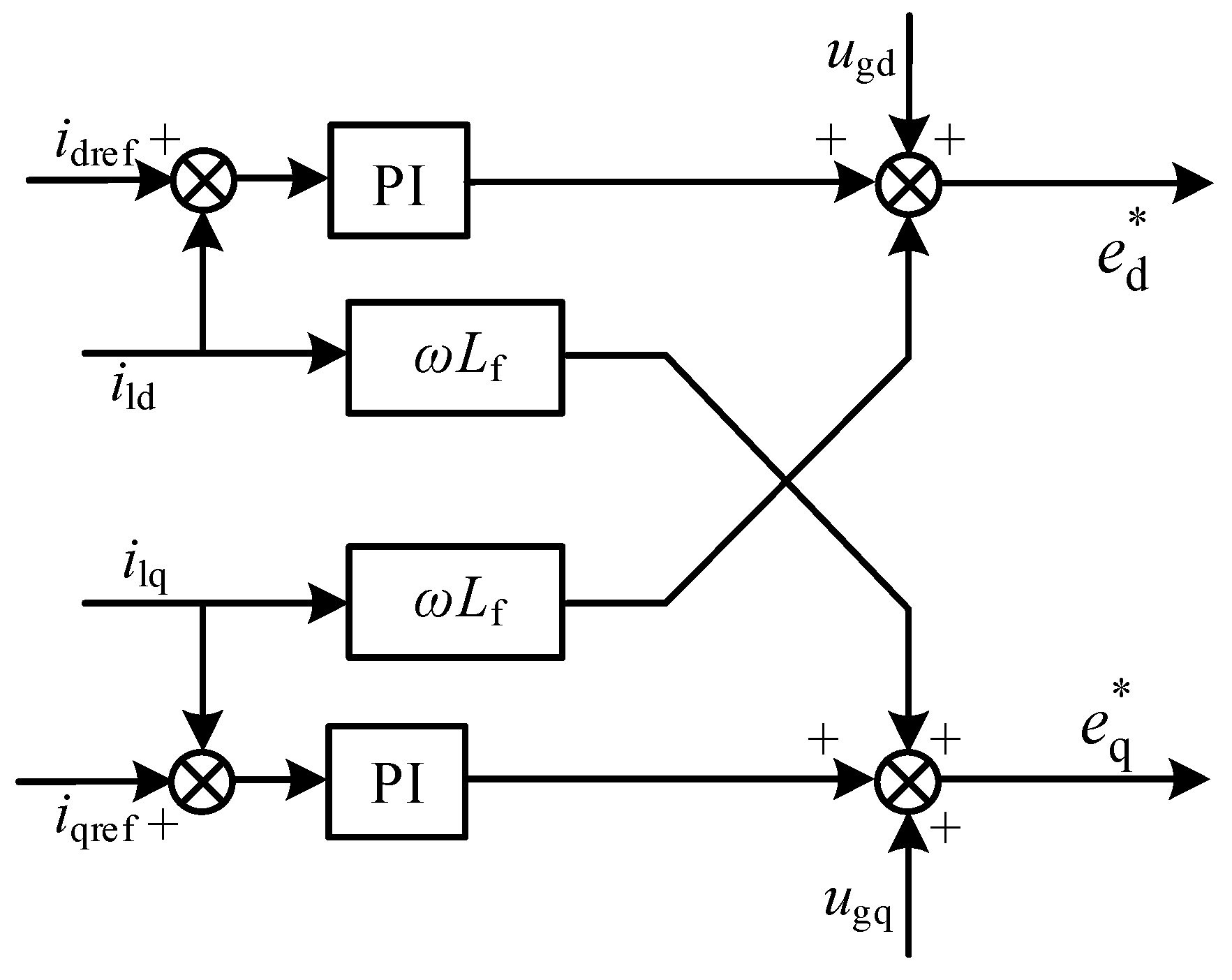
The current inner-loop control circuits for the grid-following and grid-forming modes are shown in Figure 7. They use the same control structure and control parameters, and their control equation is
e d = u gd + G ci ( s ) i dref i ld ω L f i lq e q = u gq + G ci ( s ) i qref i lq + ω L f i ld G ci ( s ) = k ip + k ii s
In the above equation, e d , e q is the converter’s output voltage reference value along the dq-axis; kpi and kii are the proportional and integral coefficients of the current inner-loop PI regulator; and Gci(s) is the transfer function of the current inner-loop PI regulator.
Under normal conditions, the actual output voltage of the converter equals its reference value, i.e., e d = e d , e q = e q . By combining Equations (3) and (4), the relationship between the reference value and the feedback value of the inductor current can be expressed as
i ld = G i ( s ) i dref i lq = G i ( s ) i qref G i ( s ) = G ci ( s ) / s L f + G ci ( s )
In the above equation, Gi(s) represents the transfer function from the reference value to the feedback value of the inductor current.
In the main circuit, the vector relationship of each physical quantity is
i g = i l i c i c = C f d u c d t = s C f u c u g = u c
In the above equation, ig and ic represent the grid-injected current vector of the converter and the filter capacitor current vector, respectively, and Cf denotes the filter capacitance value.
From Equation (6), the grid-injected current of the converter in the dq coordinate system can be expressed as
i gd = i ld s C f u gd i gq = i lq s C f u gq
The active and reactive power outputs of the converter are
P o = 1.5 u gd i gd + u gq i gq Q o = 1.5 u gq i gd u gd i gq
Substituting Equations (4), (5), and (7) into Equation (8) yields
P o = 1.5 U g G i ( s ) i dref cos δ g i qref sin δ g s C f U g 2 Q o = 1.5 U g G i ( s ) i dref sin δ g + i qref cos δ g
According to Equation (9), the active power output Po of the converter consists of two parts: the first is determined by the control of the converter, while the second is governed by the microgrid voltage. During transient processes, the microgrid voltage is considered to remain constant, i.e., Δug = 0. Therefore, the parameters affecting the output power are idref, iqref, and δg.

2.3.1. Impact of Current Reference Disturbance on Output Power

For a current reference disturbance along the q-axis iqref, the small-signal transfer functions describing its effect on the active power Po and reactive power Qo are established as shown in Equations (10) and (11), where physical quantities with a subscript of 0 represent the steady-state values of the corresponding variables.
G iq _ p ( s ) = Δ P o Δ i qref = 1.5 U g 0 G i ( s ) sin δ g 0
G iq _ q ( s ) = Δ Q o Δ i qref = 1.5 U g 0 G i ( s ) cos δ g 0
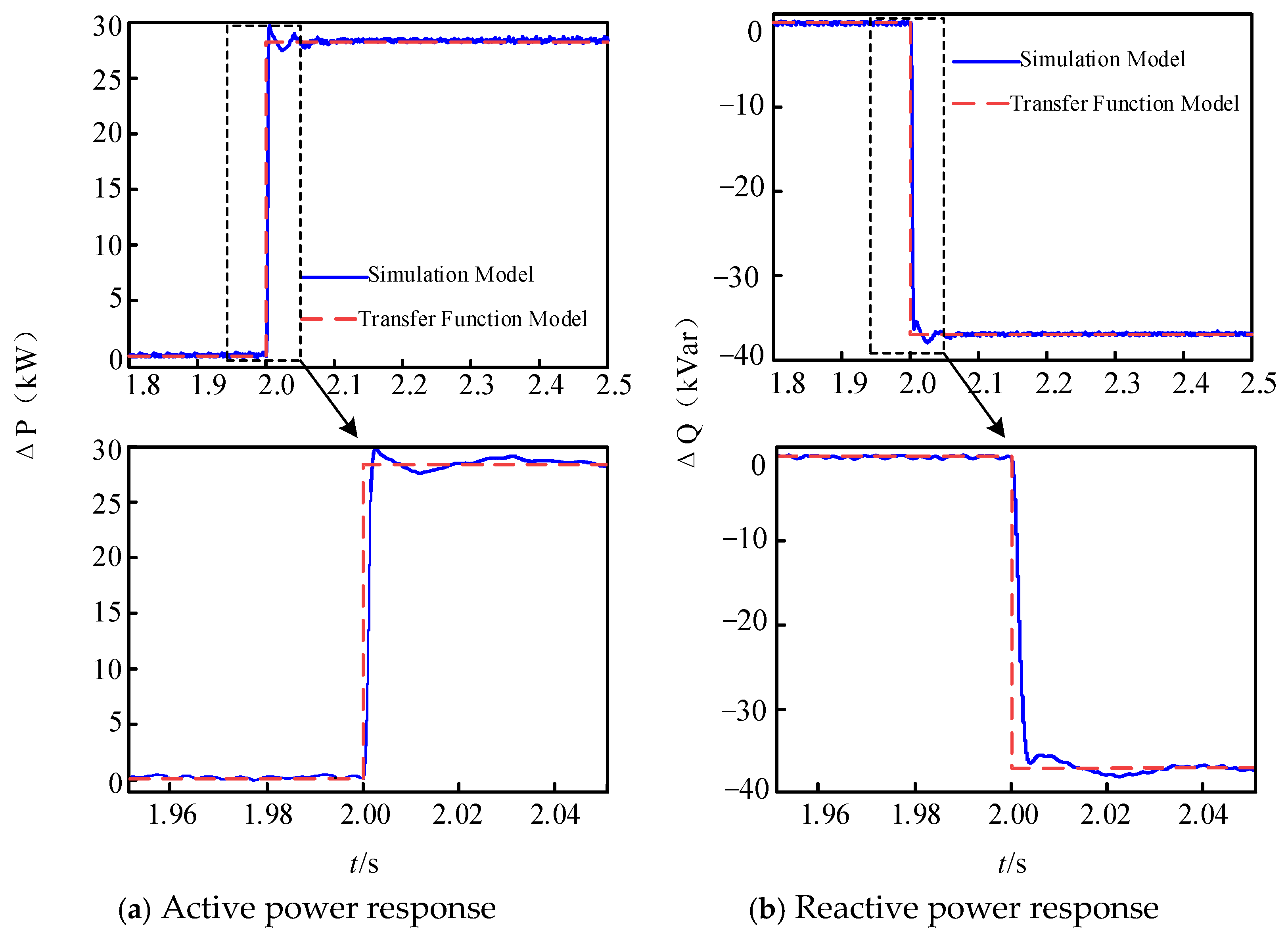
The initial value before applying the q-axis current reference disturbance is given. At t = 2 s, iqref suddenly increases from 0 to 100 A. A comparison between the responses of the transfer function model and the simulation model is shown in Figure 8. It can be observed that the transfer function model can generally and accurately represent the dynamics of the active and reactive power outputs of the converter under current reference disturbance along the q-axis.
Figure 8 shows that a sudden increase in iqref reduces both the active and reactive power outputs of the converter. Therefore, current reference disturbance along the q-axis affects both of these outputs, with a more pronounced impact on the active power.
For a current reference disturbance along the d-axis idref, the small-signal transfer functions describing its effect on the active power Po and reactive power Qo are established as shown in Equations (12) and (13):
G id _ p ( s ) = Δ P o Δ i dref = 1.5 U g 0 G i ( s ) cos δ g 0
G id _ q ( s ) = Δ Q o Δ i dref = 1.5 U g 0 G i ( s ) sin δ g 0
At t = 2 s, a step increase of 100 A is applied to idref. A comparison between the responses of the transfer function model and the simulation model is shown in Figure 9.
It can be observed that the sudden increase in idref increases the active power output of the converter while reducing its reactive power output. Thus, current reference disturbance along the d-axis affects both the active and reactive power outputs of the converter, but in opposite directions.

2.3.2. Impact of Perturbations in Control Angle on Output Power

During transient processes, if the microgrid remains stable, then Δδg = Δθc − Δθg = Δθc. Therefore, δg is primarily influenced by changes in the control angle θc. In the dq coordinate system oriented to the converter voltage vector, variations in δg will cause changes in the components of the microgrid voltage vector ug along the d and q axes.
Taking grid-following converter control as an example, the current references for its inner-loop current can be derived from the following formulas:
i dref = 2 3 u gd P ref + u gq Q ref u gd 2 + u gq 2
i qref = 2 3 u gq P ref u gd Q ref u gd 2 + u gq 2
In the above equations, Pref and Qref represent the reference values of active and reactive power for the grid-following converter.
Typically, the reference value of reactive power output from the converter is set to 0. Thus, Equations (14) and (15) can be rewritten as
i dref = 2 P ref 3 u gd 2 + u gq 2 u gd
i qref = 2 P ref 3 u gd 2 + u gq 2 u gq
From Equations (16) and (17), it can be observed that the d-axis current reference idref and the q-axis current reference iqref are influenced by ugd and ugq, respectively, while ugd and ugq are affected by δg. Therefore, disturbances in the control angle θc alter the values of idref and iqref, thereby modifying the active and reactive power outputs of the converter.
In summary, both current reference disturbances and control angle disturbances affect the active and reactive power outputs of the converter, either directly or indirectly. In low-capacity AC microgrids, variations in the converter’s active and reactive power outputs can significantly impact the frequency and voltage amplitude of the microgrid. Hence, it is imperative to implement effective measures to suppress these disturbances during mode transitions. To this end, the following sections present our proposed solutions: a novel VSG angle-tracking technique to mitigate control angle disturbance and a current-command latching scheme to eliminate current reference disturbance.

3. Research on Key Technologies for Seamless Switching

3.1. VSG Angle-Tracking Technology for Mitigating Control Angle Disturbance

The foundation of our approach leverages the fact that, in a dual-mode-switching control architecture, both control modes can remain active during normal operation. This allows the phase-locked loop (PLL) of the grid-following mode to continuously track the microgrid’s phase angle even when the converter is operating in grid-forming mode. Consequently, when switching from grid-forming to grid-following mode, the control angle can remain unchanged, providing a basis for seamless transition. However, the critical challenge arises during the switch from grid-following to grid-forming mode, where the self-synchronizing characteristic of grid-forming control prevents its voltage and angle outputs from instantly tracking the microgrid. This lag introduces control angle disturbances. To address this specific problem, we introduce a control angle-tracking technique into the VSG control loop.

3.1.1. VSG Control Angle-Tracking Technology Based on PI Regulator

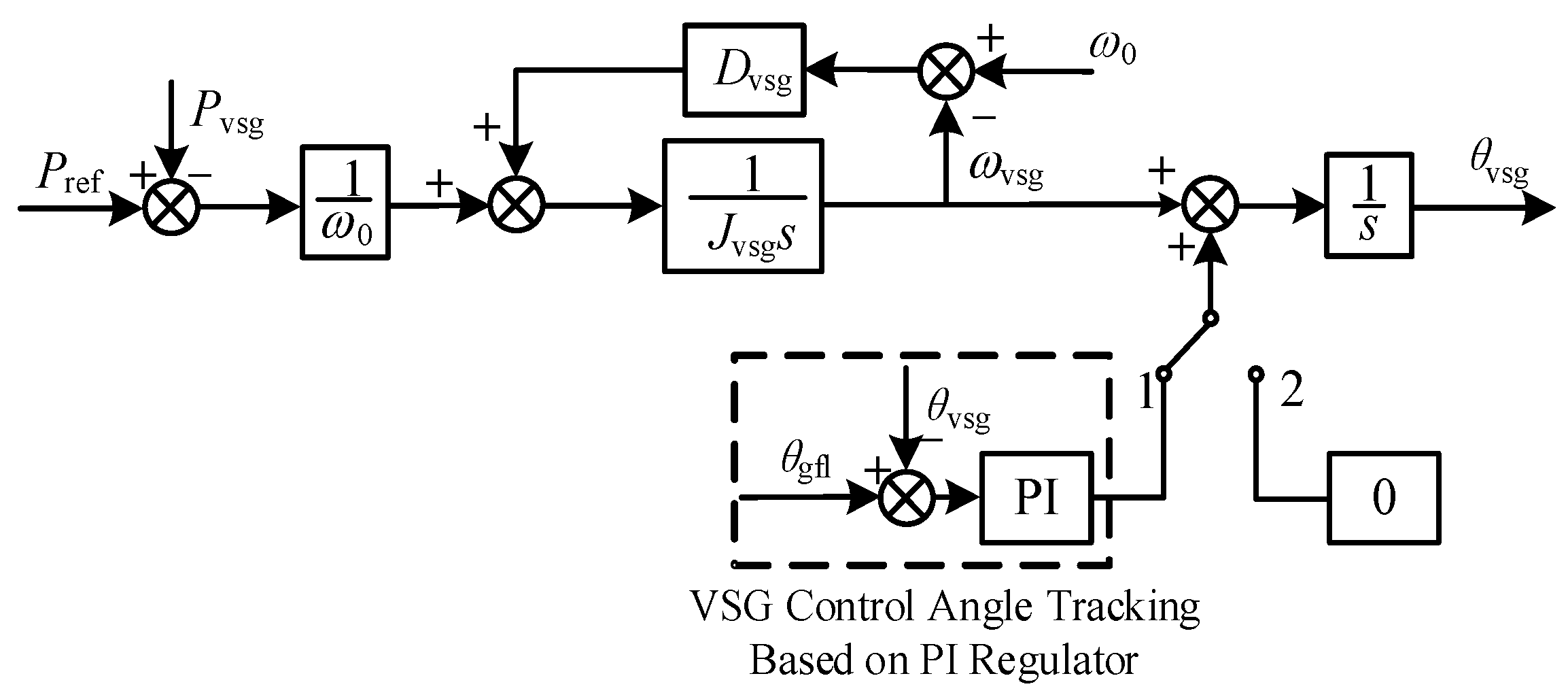
The conventional control angle-tracking technique utilizes a PI regulator-based VSG control angle-tracking method, with a block diagram of this control strategy illustrated in Figure 10. When the control mode switch is set to position “2”, the converter operates in grid-forming control mode, and the active power control loop of the VSG remains unaltered. When the control mode switch is set to position “1”, the converter operates in grid-following control mode. In this state, the grid-forming control loop activates the VSG control angle-tracking function. The control angle of the grid-following mode θgfl is subtracted from that of the grid-forming mode θvsg, and the resulting error is fed into the PI regulator. The output of the PI regulator is then superimposed onto the reference frequency ωvsg generated by the VSG active power control loop. The adjusted frequency signal is integrated to obtain an updated VSG control angle. If θvsg is less than θgfl, the input to the PI regulator is positive, leading to an increase in its output. This raises the reference frequency ωvsg, thereby advancing the output phase θvsg of the VSG. Conversely, if θvsg is greater than θgfl, the process reduces ωvsg and delays θvsg. This mechanism ultimately enables steady-state error-free tracking of the VSG control angle.
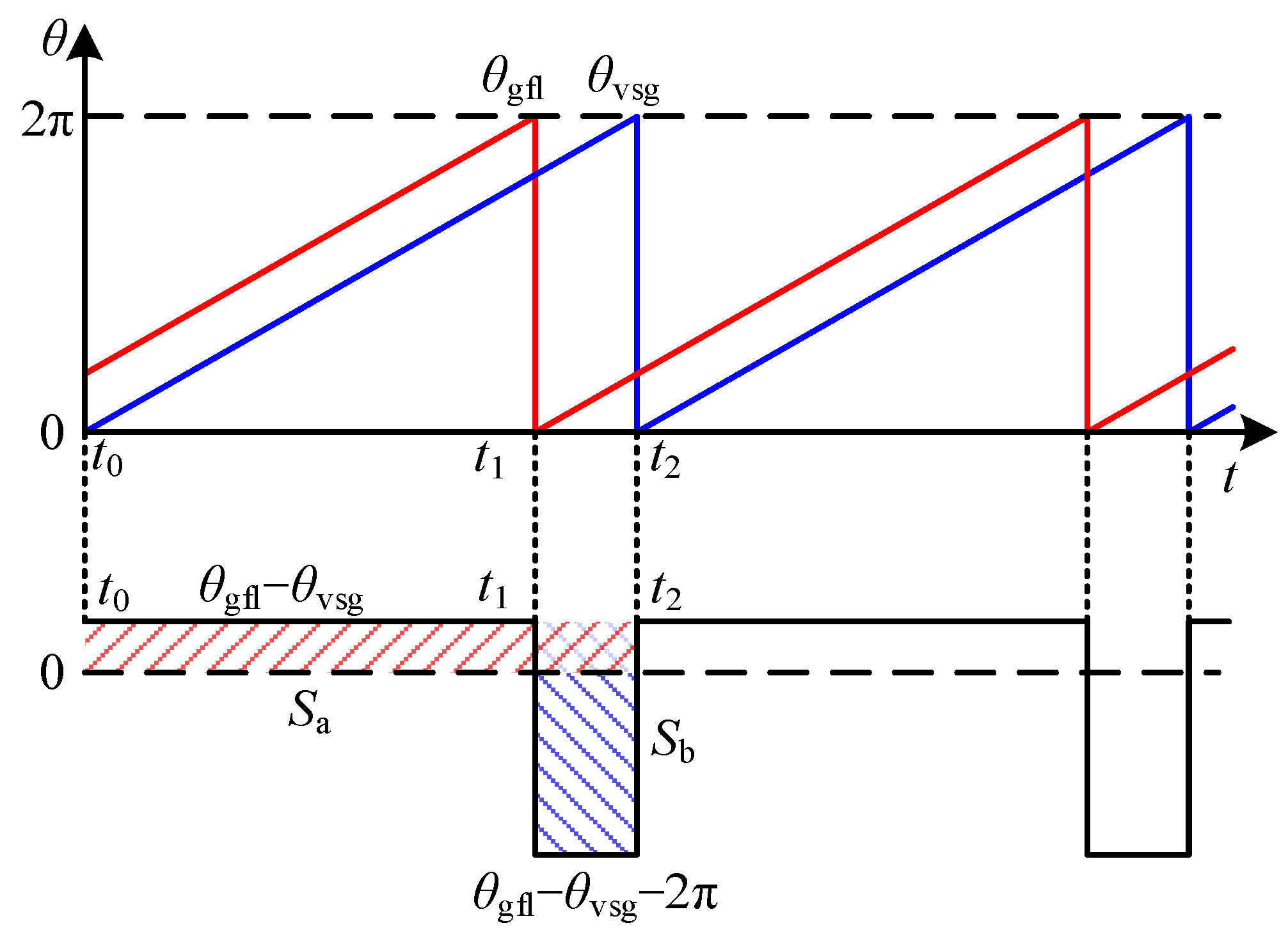
However, since the control angle signal varies periodically within the range of 0 to 2π, its value undergoes abrupt changes from 2π to 0. Consequently, the difference signal generated by subtracting two distinct control angle signals also exhibits positive and negative jumps, as illustrated in Figure 11.
In Figure 11, it is assumed that the control angle of the grid-following mode determines that of the grid-forming mode. The interval from t0 to t2 represents one full cycle of the control angle difference signal. At time t0 (the starting point), the control angle of the grid-following mode jumps at t1, and the control angle of the grid-forming mode jumps at t2.
During the period t0t1, both control angles are in their rising phase. Throughout this interval, the control angle difference signal remains constant at θgflθvsg. At time t1, θgfl jumps from 2π in the previous cycle to 0 in the next cycle, while the relatively lagging θvsg is still increasing. As a result, the control angle difference signal undergoes a negative jump at t1, changing to θgflθvsg − 2π, and maintains this value during t1t2. At time t2, θvsg jumps from 2π in the previous cycle to 0 in the next cycle. Therefore, the control angle difference signal exhibits a positive jump at t2, returning to θgflθvsg. In summary, the control angle difference signal undergoes fixed-magnitude negative and positive jumps within each cycle. This causes the output of the PI regulator to also jump. If this signal is directly fed into the VSG active power control loop, it will prolong the adjustment time or even prevent successful control angle tracking.
The jump in the control angle difference primarily affects the proportional part of the PI regulator. Therefore, neglecting the integral effect, the phase-angle adjustment Δθ of the VSG after one complete regulation cycle can be expressed as
Δ θ = t 0 t 1 k pc θ gfl θ vsg d t + t 1 t 2 k pc θ gfl θ vsg 2 π d t = k pc t 0 t 2 θ gfl θ vsg d t 2 π t 2 t 1 = k pc S a S b
In the above equation, kpc represents the proportional gain of the PI regulator, and Sa and Sb denote the forward- and reverse-regulation areas, respectively.
From Equation (18), it can be observed that different sizes of Sa and Sb correspond to different control angle-tracking processes:
(1)
If Sa > Sb, meaning the forward-regulation effect of Sa is greater than the reverse-regulation effect of Sb, then Δθ > 0. The control angle difference between the two modes decreases, and the VSG can achieve control angle tracking. However, the reverse-regulation effect of Sb prolongs the adjustment time.
(2)
If Sa = Sb, meaning the forward-regulation effect of Sa balances the reverse-regulation effect of Sb, then Δθ = 0. The control angle difference between the two modes remains constant, and the VSG cannot achieve control angle tracking.
(3)
If Sa < Sb, meaning the forward-regulation effect of Sa is smaller than the reverse-regulation effect of Sb, then Δθ < 0. The control angle difference between the two modes further increases until the VSG control angle lags by one cycle and becomes equal to that of the grid-following mode. In this case, the VSG can eventually achieve control angle tracking, but the adjustment time is excessively long.
From the above analysis, it can be concluded that the jump in the control angle difference has a negative impact on VSG control angle tracking. To reduce the adjustment time and improve the accuracy of the VSG control angle-tracking strategy, it must be designed to eliminate the adverse effects of the periodic jumps in the control angle difference.

3.1.2. VSG Control Angle-Tracking Technology Based on Constructed Function

To eliminate the negative impact of periodic jumps in the control angle difference, this paper proposes a VSG control angle-tracking technique based on a constructed function. By using a function construction method, the periodically jumping control angle difference signal is transformed into a smooth regulation signal.
As observed in Figure 11, the magnitude of the control angle difference before and after a jump differs by 2π. Recalling the periodic nature of trigonometric functions, when the argument changes by 2π, the output value of the trigonometric function remains unchanged. Therefore, a trigonometric function can be constructed with the control angle difference as the argument. Feeding the output of this constructed function into the PI regulator eliminates the influence of jumps in the control angle difference.
Among trigonometric functions, the cosine function maintains continuity and monotonicity in the range of 0 to π. Thus, the cosine function relationship is constructed as follows:
y = cos θ gfl θ vsg 2 π + 1 2 π < θ gfl θ vsg π cos θ gfl θ vsg 1 π < θ gfl θ vsg < 0 cos θ gfl θ vsg + 1 0 < θ gfl θ vsg π cos θ gfl θ vsg + 2 π 1 π < θ gfl θ vsg < 2 π
From Equation (19), the constructed cosine function curve can be derived as shown in Figure 12. To ensure that the output regulation signal of the constructed trigonometric function maintains the same direction (positive or negative) as the control angle difference signal, the original cosine function is negated and shifted upward by one unit. This results in a monotonically increasing function curve in the interval (0, π], as shown by segment b in the figure. If the control angle difference θgflθvsg falls within (0, π], it indicates that θgfl leads θvsg by 0 to π radians. In this case, a positive regulation signal needs to be superimposed onto the active power control loop of the VSG. When the control angle difference jumps from θgflθvsg to θgflθvsg − 2π, the constructed cosine function shifts from segment b to segment a. Although the argument jumps by 2π, the magnitude and trend of the output regulation signal from the constructed cosine function remain unchanged. If the control angle difference θgflθvsg lies within [−π, 0), it means that θgfl lags behind θvsg by 0 to π radians. A negative regulation signal should then be superimposed onto the VSG active power control loop. Considering that the constructed function y1 = −cos(θgflθvsg) + 1 is non-negative in the interval [−π, 0), its opposite function y2 = cos(θgflθvsg)-1 is constructed, as shown by segment c. Similarly, when the control angle difference jumps, the constructed cosine function shifts from segment c to segment d, and the magnitude and trend of the output regulation signal remain unaffected.
The proposed constructed cosine function method ensures the smoothness and continuity of the phase-angle compensation signal, thereby eliminating the negative effects of periodic jumps in the control angle difference.
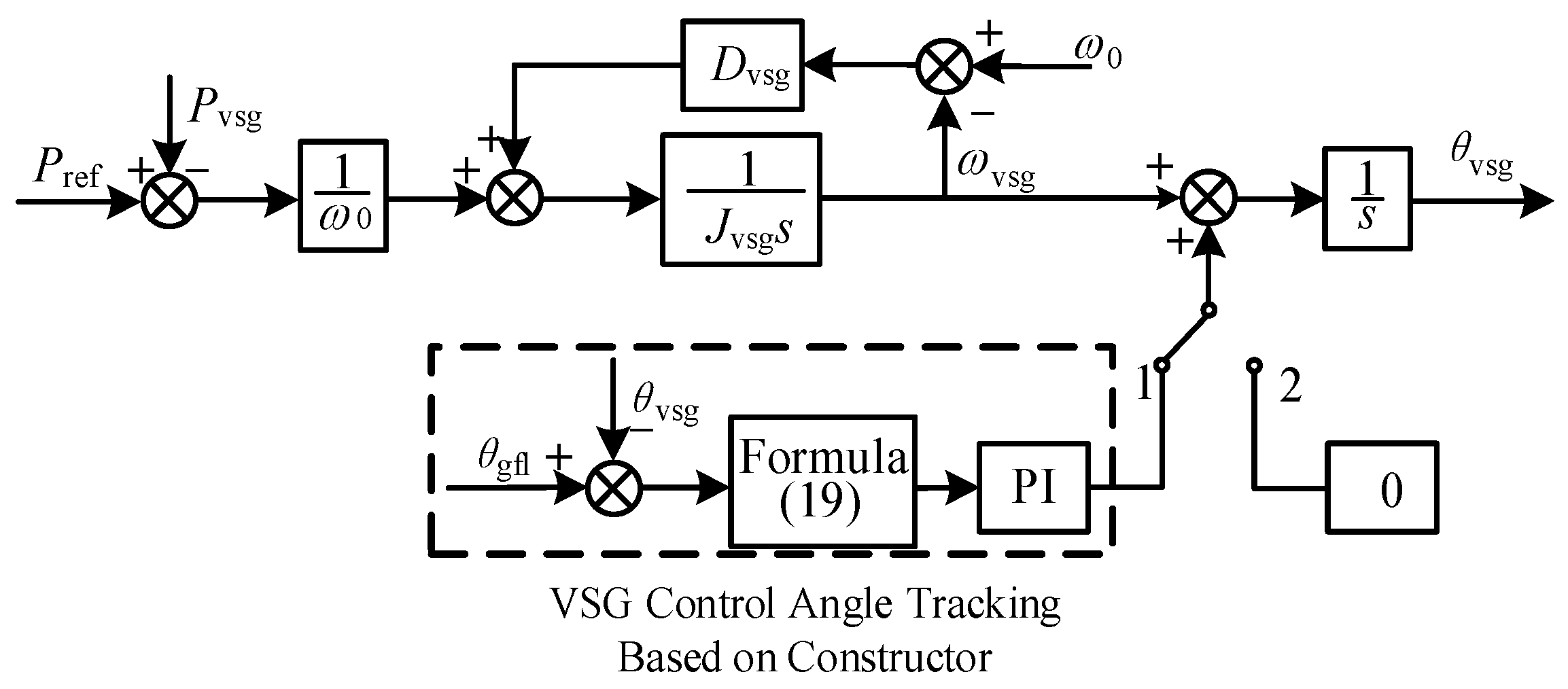
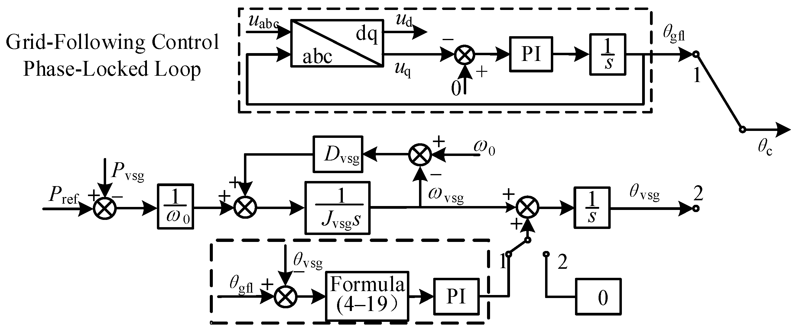
Figure 13 shows a block diagram of the VSG control angle-tracking strategy based on the constructed cosine function. The overall control approach is largely similar to the PI regulator-based VSG control angle-tracking method. However, while the latter directly feeds the angle difference into the PI regulator, the former first processes the angle difference through a constructed trigonometric function to convert it into a monotonic and continuous regulation signal before sending it to the PI regulator.

3.2. Disturbance-Free Switching Technology for Control Angle Reference Disturbance

As mentioned above, this study adopts a constructed-function-based VSG control angle-tracking technique to address control angle reference disturbances. Figure 14 shows a block diagram of disturbance-free switching of the control angle after applying the constructed function.
As illustrated in Figure 14, when the control mode switch is set to position “1”, the grid-forming control incorporates the VSG control angle-tracking technique, enabling θvsg to track θgfl in real time. When the control mode switch is set to position “2”, the grid-following control uses a phase-locked loop (PLL) to track θvsg in real time. This ensures that the control angle θc of the energy storage converter remains essentially unchanged during mode switching.

3.3. Current Reference-Disturbance-Free Switching Technology

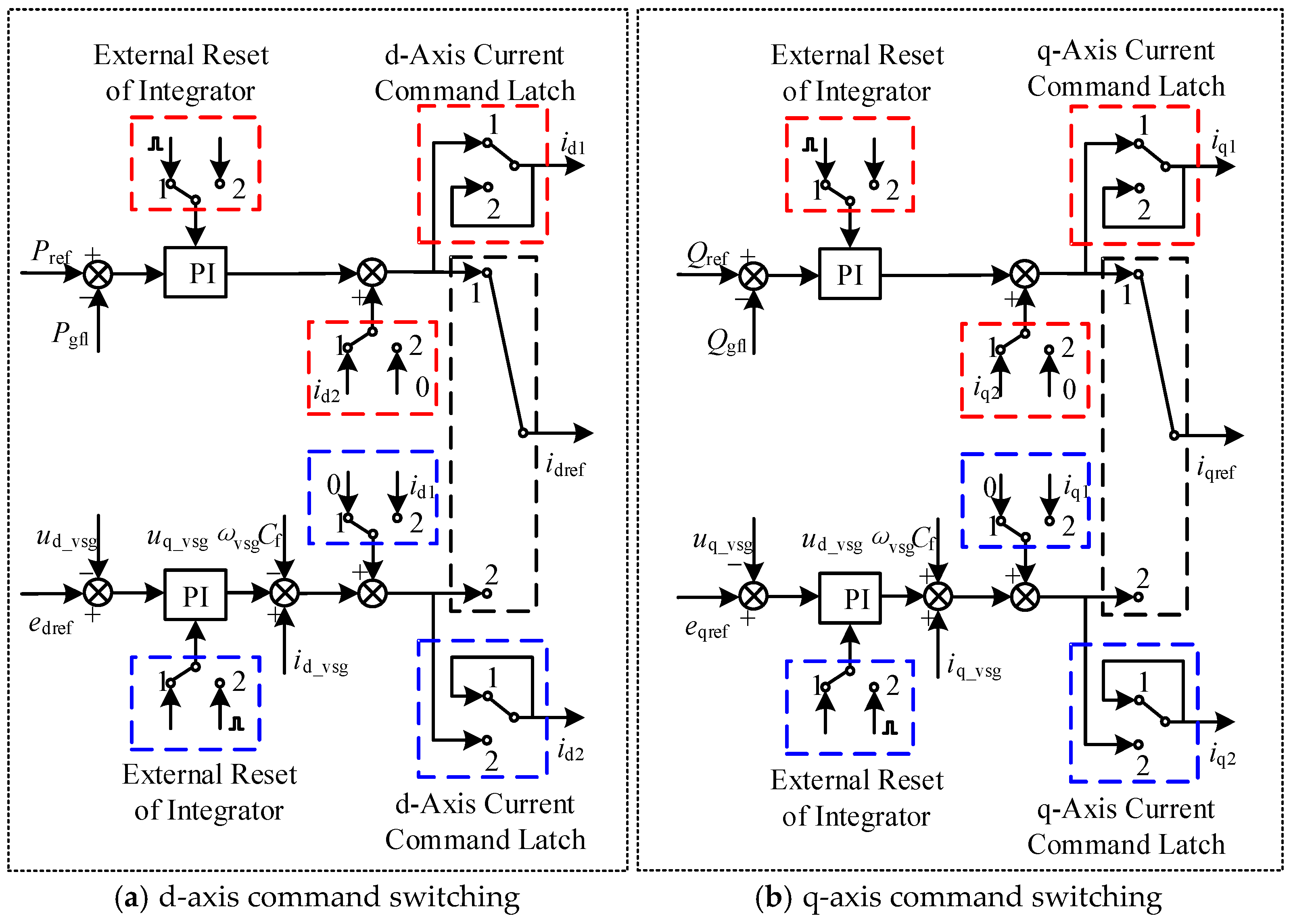
The current reference-disturbance-free switching scheme is shown in Figure 15. Figure 15a shows a block diagram of the d-axis current reference-disturbance-free control scheme, while Figure 15b shows a block diagram of the q-axis current reference-disturbance-free control scheme. Both share essentially the same control structure, so Figure 15a is taken as an example to explain the current reference-disturbance-free switching process. When the control mode switch is set to position “1”, the energy storage converter operates in grid-following mode. Its d-axis current reference is provided by the power outer loop of the grid-following control. During the converter’s operation in this mode, the output current reference id1id1 from the power outer loop is sampled. When the control mode switch is set to position “2”, the energy storage converter operates in grid-forming mode. Its d-axis current reference is supplied by the voltage outer loop of the grid-forming control. In this mode, the power outer-loop current reference id1id1 is latched and used as a baseline value for the voltage outer loop. The output current reference id2id2 from the voltage outer loop is sampled, and the integrator of the voltage outer loop is simultaneously reset.
As illustrated in Figure 15, the disturbance-free switching of current references ensures the continuity of control commands at the instant of mode transition by dynamically latching and synchronizing the current reference values of the inner loop between the two control modes.

3.4. Overall Control Algorithm

The overall control algorithm is illustrated in Figure 16.
The overall logic flow of the proposed disturbance-free switching strategy is summarized in Figure 16. The process begins with the continuous monitoring of grid status and local measurements. Upon receiving a mode-switching command, the system initiates a pre-synchronization procedure. This critical phase involves three synchronized actions: (1) activating the VSG angle-tracking technique to align the phase angles between the two modes, (2) latching the current reference values (id1, iq1) from the outgoing controller, and (3) initializing the integrator states of the incoming controller’s voltage loop to prevent windup. This coordinated approach ensures the continuity of both the phase angle and current reference commands. Finally, the control authority is seamlessly transferred, and the system resumes operation in the new mode with minimal transient disturbance.

4. Simulation Verification and Result Analysis

4.1. Simulation Model Setup and Parameter Configuration

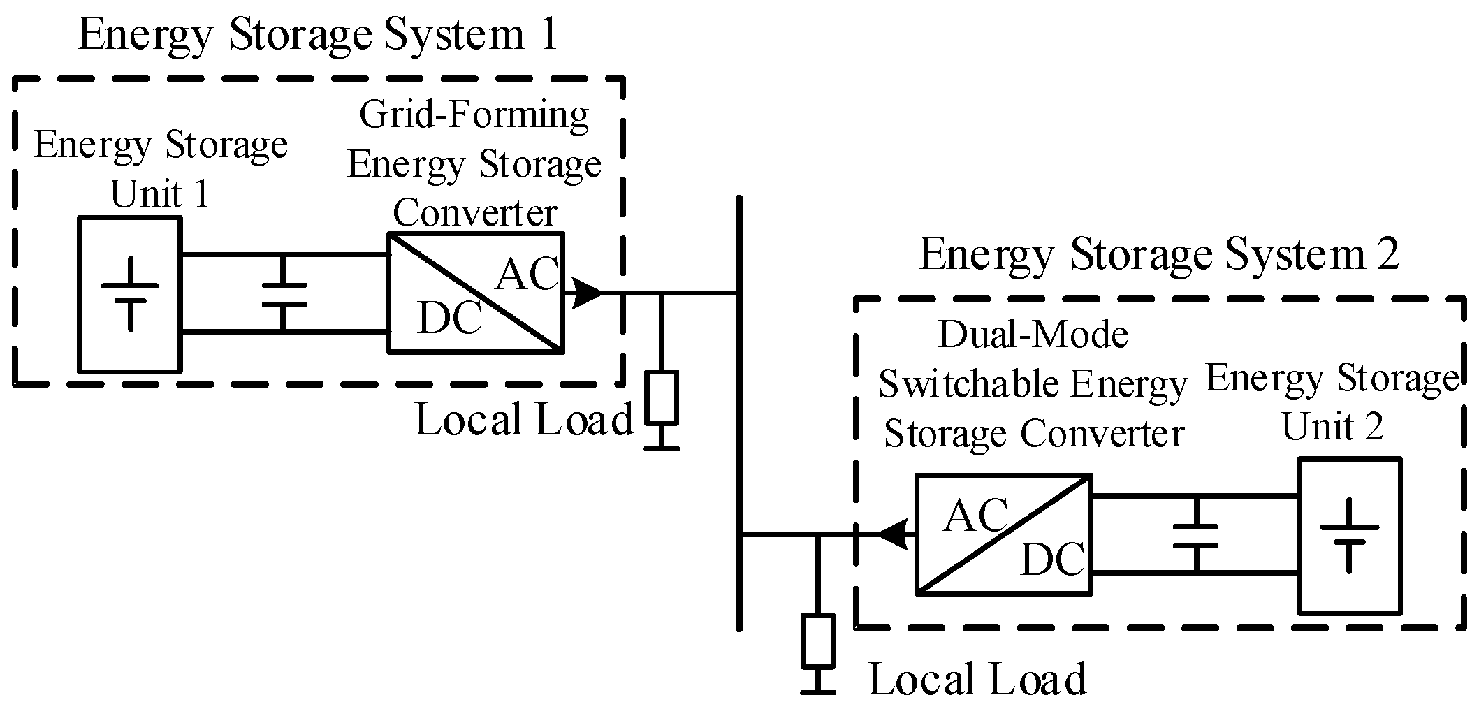
An AC system, as shown in Figure 17, was built in MATLAB R2021b/Simulink. The system parameters are listed in Table 1. In the diagram, both Energy Storage System 1 and Energy Storage System 2 are connected to 300 kW local loads. Energy Storage System 1 employs grid-forming control and consistently provides stable voltage and frequency to the AC system. Energy Storage System 2 utilizes an energy storage converter capable of switching between grid-following and grid-forming control modes.

4.2. Validation of Control Angle-Tracking Technology’s Effectiveness

To verify the superiority of the constructed-function-based VSG control angle-tracking algorithm proposed in this paper, three simulation models were built in Simulink for comparative analysis: A model without a VSG control angle-tracking strategy, a model incorporating the conventional PI regulator-based VSG control angle-tracking strategy, and a model incorporating the constructed-function-based VSG control angle-tracking strategy.
Details of the simulation case analysis are presented below.

4.2.1. Control Angle-Tracking Strategy Without VSG

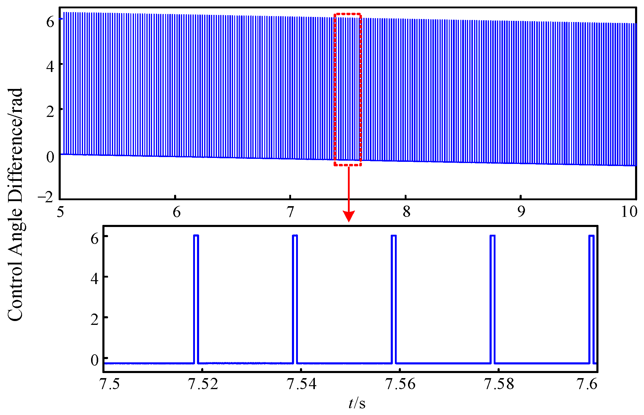
In this strategy, the dual-mode energy storage converter operates with an active power output of 300 kW. At t = 5 s, it switches from grid-forming to grid-following mode. Figure 18 shows the control angle difference θgflθvsg that occurs without the VSG control angle-tracking technique. From the figure, it can be observed that the control angle difference is nearly zero at the switching moment (t = 5 s). However, as time progresses, the absolute value of the control angle difference gradually increases. This indicates that after the converter switches to grid-following mode, its grid-forming control loop no longer participates in microgrid operation. Due to the slight difference in output power between grid-forming and grid-following modes, the control angles of the two operating modes also diverge. Without effective control measures, the control angle difference between the two modes continues to grow, adversely affecting the mode-switching capability of the energy storage converter.
Zooming into the control angle difference curve between t = 7.5 s and t = 7.6 s in Figure 18, periodic jumps in the control angle difference are clearly visible. Each cycle exhibits both positive and negative jumps, consistent with the theoretical analysis. Unlike the scenario in Figure 11, the simulation shows that the grid-following control angle θgfl lags behind the grid-forming control angle θvsg. Consequently, the control angle difference first experiences a positive jump, followed by a negative jump.

4.2.2. PI Regulator-Based VSG Control Angle-Tracking Strategy

In this strategy, the dual-mode energy storage converter operates with an active power output of 300 kW. At t = 5 s, it switches from grid-forming to grid-following mode. At t = 8 s, the PI regulator-based VSG control angle-tracking strategy is activated in the VSG active power control loop. The resulting control angle difference θgflθvsg is shown in Figure 19.
Figure 19a provides an overview of the variation in the control angle difference. Under the action of the PI regulator, the control angle difference gradually decreases and approaches zero after approximately 0.5 s of adjustment. Figure 19b shows a zoomed-in view of the control angle difference between t = 8 s and t = 8.3 s. It can be observed that the control angle difference exhibits a “sawtooth” shape. This is caused by the reverse-regulation area Sb, generated by control angle jumps, which counteracts the phase angle adjustment. This scenario corresponds to the condition where Sa > Sb. The presence of Sb prolongs the adjustment time. Figure 19c displays a zoomed-in view of the control angle difference between t = 9.7 s and t = 10 s. It can be seen that the control angle difference remains constant at a non-zero value. This scenario corresponds to the condition Sa = Sb. Although the control angle difference persists, the forward-regulation effect of Sa and the reverse-regulation effect of Sb are balanced. As a result, the control angle difference does not decrease further, and the VSG fails to achieve control angle tracking.

4.2.3. Constructed-Function-Based VSG Control Angle-Tracking Strategy

In this strategy, the simulation conditions remain the same as above. At t = 8 s, the constructed-function-based VSG control angle-tracking strategy is activated in the VSG active power control loop. The resulting control angle difference θgflθvsg is shown in Figure 20.
Figure 20a provides an overview of the variation in the control angle difference. By incorporating the constructed-function module at the input of the PI regulator, the control angle difference rapidly decreases and reaches zero after only approximately 0.1 s of adjustment. Figure 20b shows a zoomed-in view of the control angle difference between t = 8 s and t = 8.3 s. It can be observed that after eliminating the reverse-regulation effect of Sb, the transient adjustment process of the control angle difference is significantly shortened. The curve appears smooth and exhibits a monotonically decreasing trend. Figure 20c displays a zoomed-in view of the control angle difference between t = 9.7 s and t = 10 s. Although a control angle difference still exists, its magnitude is very small, fluctuating near zero.
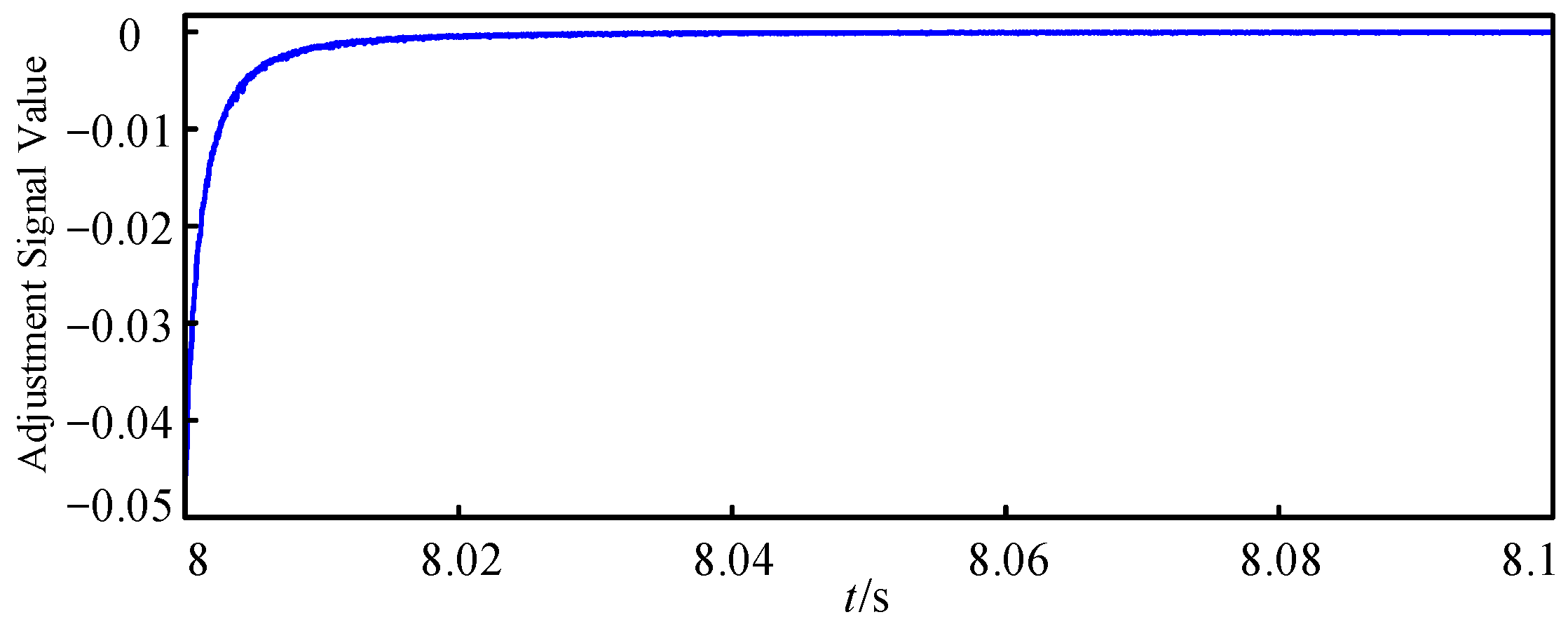
Figure 21 shows the regulation signal output by the constructed trigonometric function, with a segment from t = 8 s to t = 8.1 s extracted. As illustrated, the polarity of the regulation signal matches that of the control angle difference. The signal is smooth, monotonic, and continuous, eliminating the negative effects associated with directly using the control angle difference as the regulation signal. When the control angle difference is zero, the regulation signal also becomes zero, marking the end of the phase-angle adjustment process.
The comparative validation of the three simulation cases above clearly demonstrates the advantages of the constructed-function-based VSG control angle-tracking strategy over other control schemes. This strategy ensures both rapid adjustment speed and high tracking accuracy, thereby verifying the effectiveness and superiority of the constructed-function-based control angle-tracking algorithm proposed in this paper.

4.3. Performance Validation of the Overall Disturbance-Free Switching Scheme

The overall disturbance-free switching control strategy combines the schemes from Figure 14 and Figure 15. To validate the effectiveness of the proposed approach, two simulation models—one without and one with the disturbance-free switching control strategy for the energy storage converter—were developed in MATLAB R2021b/Simulink based on the AC system shown in Figure 17 for comparative analysis.

4.3.1. System Response Without Disturbance-Free Switching Strategy

(1)
Switching the Dual-Mode Energy Storage Converter from Grid-Forming to Grid-Following Mode
The dual-mode energy storage converter switches from grid-forming to grid-following mode at t = 5 s. The local load of the energy storage system remains unchanged before and after switching, and the frequency and voltage of the AC system are shown in Figure 22.
Figure 22 shows that, even without the disturbance-free switching technique, the transition from grid-forming to grid-following mode of the dual-mode energy storage converter is smooth, with no significant transient process taking place during the switching. This is because the output power of the dual-mode energy storage converter is the same before and after switching, resulting in no noticeable variation in the current reference. Additionally, the phase-locked loop (PLL) of the grid-following control continues to track the phase angle even when the converter operates in grid-forming mode, ensuring minimal change in the control angle after the transition.
Given that the transition from grid-forming to grid-following mode is smooth even without the disturbance-free switching technique, for simplicity, only the switching process from grid-following to grid-forming mode will be analyzed subsequently.
(2)
Switching the Dual-Mode Energy Storage Converter from Grid-Following to Grid-Forming Mode
The dual-mode energy storage converter switches from grid-following to grid-forming mode at t = 10 s. The local load of the energy storage system remains unchanged before and after the switching. The frequency and voltage of the AC system are shown in Figure 23.
Figure 23 shows that, due to the absence of the disturbance-free switching technique, a noticeable transient process occurs when the energy storage converter switches from grid-following to grid-forming mode. The maximum-frequency transient peak reaches 50.3 Hz, which is 0.3 Hz above the baseline value of 50 Hz. The magnitude of phase A voltage during the transient process peaks at 229.6 V, resulting in an absolute deviation of 81.4 V from the baseline value of 311 V, representing a change of 26.2%. During the mode-switching transient, not only is the transient peak significant, but the recovery time to steady state is also prolonged by approximately 0.903 s.

4.3.2. System Response with Disturbance-Free Switching Strategy

To reduce switching disturbances, the disturbance-free switching control technique is integrated into the dual-mode energy storage converter control system. The simulation conditions remain unchanged: the switching from grid-following to grid-forming mode is performed at t = 10 s, and the local load of the energy storage system is kept constant before and after switching. The frequency and voltage of the AC system are shown in Figure 24. After implementing the disturbance-free switching control strategy, the transient peak of the system frequency is significantly reduced, with a maximum value of only 50.02 Hz. The magnitude of the phase A voltage decreases to only 310.6 V. Furthermore, the transient duration is substantially shortened to approximately 0.13 s, demonstrating the effectiveness of the proposed disturbance-free switching control strategy for the dual-mode energy storage converter.

4.4. Hardware-in-the-Loop Experimental Validation

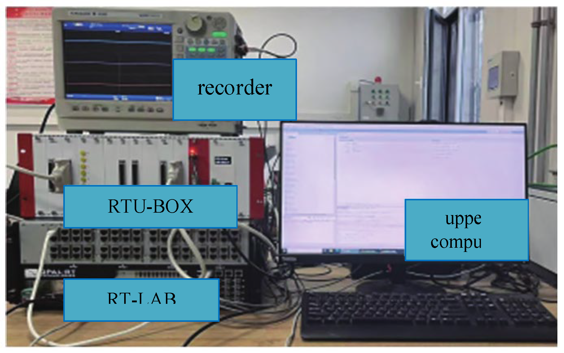
To further verify the performance of the proposed disturbance-free switching strategy on actual controller hardware and its potential for engineering applications, this section conducts high-precision real-time simulation tests based on the hardware-in-the-loop (HIL) experimental platform shown in Figure 25, using the system topology depicted in Figure 17.

4.4.1. Experimental Platform Architecture

The HIL experimental platform, as illustrated in Figure 25, was constructed to validate the proposed control strategy under realistic conditions. The platform primarily consists of an upper computer, an Opal-RT Technologies RT-LAB OP4510 real-time simulator (Montreal, QC, Canada), an RTU-BOX controller, and a Yokogawa DL850E ScopeCorder waveform recorder (Tokyo, Japan). The detailed configuration and workflow of the platform are as follows:
(1)
Upper Computer: A host PC running MATLAB/Simulink (version R2023a) was used to develop and compile the detailed electromagnetic transient model of the power circuit and the main grid.
(2)
Real-Time Simulator (RT-LAB OP4510): Serving as the core for model execution, the simulator is equipped with a powerful Intel Xeon multi-core processor and utilizes the ARTEMIS solver for high-fidelity electrical system simulation. It receives the compiled model from the upper computer and executes it on its real-time processor with a fixed simulation time-step of 50 μs, accurately simulating the dynamic characteristics of the physical plant.
(3)
Controller (RTU-BOX): This unit acts as the physical control hardware, with the proposed disturbance-free switching algorithm embedded. Its core is a Texas Instruments TMS320F28335 Digital Signal Processor (DSP). The controller interfaces with the simulator via its analog-to-digital converters (ADCs), acquiring real-time voltage and current signals with 16-bit resolution at a sampling frequency of 10 kHz. Based on these measurements and the embedded algorithm, it calculates and generates PWM modulation signals in real time to achieve closed-loop control of the virtual plant.
(4)
Waveform Recorder (Yokogawa DL850E): A high-precision ScopeCorder was employed for the synchronous, high-speed acquisition of electrical quantities (voltages, currents) and internal control signals from both the RT-LAB simulator and the RTU-BOX controller during experiments, enabling detailed post-processing and analysis.
This integrated platform effectively separates the “controlled plant” (simulated in RT-LAB) from the “controller” (the physical RTU-BOX), creating a rigorous test environment that closely mimics real engineering conditions. This setup is instrumental in validating the performance and robustness of the proposed control algorithm within a real-time, closed-loop framework.

4.4.2. Experimental Scheme and Result Analysis

For clear comparison, two modes were setup for the experiment: The first mode does not enable the disturbance-free switching strategy; The second mode enables the disturbance-free switching strategy. The simulation condition was set to switch from grid-following mode to grid-forming mode at 10 s, with the local load of the energy storage system unchanged before and after the switch. The frequency and voltage waveforms of the AC system under the two modes are shown in Figure 26 and Figure 27.
As shown in Figure 26 and Figure 27, the experimental results are highly consistent with the aforementioned simulation conclusions: When the disturbance-free switching strategy is not enabled, mode switching causes severe power and voltage oscillations. The maximum frequency deviation reaches ±0.5 Hz, the voltage amplitude fluctuation exceeds 8%, and the system experiences an unstable process lasting about 0.903 s before gradually recovering to a steady state. When the proposed disturbance-free switching strategy is enabled, the switching process is very smooth. The frequency deviation is strictly limited to within ±0.02 Hz, the voltage amplitude fluctuation is less than 1%, and the transient process is shortened to 0.13 s.
The HIL experimental results strongly confirm the effectiveness and advanced nature of the proposed strategy. Its excellent performance in real-time closed-loop tests demonstrates that the algorithm can not only operate in a simulation environment but also has the potential to run stably on real physical controllers, laying a solid foundation for subsequent engineering applications.

4.5. Limitations and New Perspectives of Work

While this study proposes an effective disturbance-free switching strategy and validates it through simulations, we recognize several limitations that present valuable opportunities for future research.
Firstly, the theoretical model in this work is based on idealized assumptions of a “constant microgrid voltage” and “negligible line impedance” to simplify the analysis and highlight the core control concept. We acknowledge that, in practical dynamic-load scenarios, voltage fluctuations and line impedance can cause power coupling and voltage drops, which may influence the dynamic performance of the switching strategy to some extent. Secondly, the current simulation validation was conducted primarily in a simplified two-converter system under standard operating conditions. To more comprehensively evaluate the robustness and scalability of the proposed strategy, testing under more diverse and extreme conditions is necessary, such as evaluating its performance in systems with a large number of distributed energy resources and consumers with uncertain loads, under varying grid strengths (e.g., high/low short-circuit ratios), and during multiple consecutive switching events. Finally, while the simulation results demonstrate excellent stability, this study primarily provides an experimental validation. A formal theoretical analysis on the stability and convergence of the proposed control method, such as using Lyapunov stability theory or small-signal modeling, is lacking. Such an analysis is crucial for providing rigorous guarantees of system performance under all operating conditions and for optimizing controller parameters.
Consequently, we plan to undertake the following work in the future:
(1)
Conduct a theoretical stability and convergence analysis: Employ formal methods (e.g., Lyapunov’s direct method) to provide a rigorous mathematical proof of the system’s stability and the convergence of the proposed angle-tracking and current-latching mechanisms.
(2)
Quantify the impact of non-ideal conditions: Theoretically analyze and experimentally investigate the specific impact of line impedance and voltage fluctuations on the transient performance of the switching process.
(3)
Expand testing to complex microgrid scenarios: Develop more comprehensive simulation and experimental cases to evaluate system performance in realistic environments with high penetration of distributed energy resources, significant load uncertainty, and varied grid strengths to verify coordination capability and robustness.
(4)
Investigate multi-converter coordination: Study potential coordination mechanisms between multiple converters employing the proposed strategy to ensure system-wide stability during mode transitions.
Addressing these aspects will significantly enhance the engineering practicality, universality, and theoretical foundation of the proposed strategy for real-world microgrid applications.

5. Conclusions

This paper addresses the issue of transient disturbances during the transition between grid-following and grid-forming modes in energy storage converters; we conduct systematic research including a theoretical analysis, a methodological proposal, and simulation validation, with the aim of achieving smooth frequency and voltage transitions during mode switching and ensuring the secure and stable operation of microgrids. The main conclusions of this study are as follows:
First, we reveal the mechanism behind transient disturbances during dual-mode switching. Our theoretical analysis and simulation results demonstrate that step changes in current references and phase jumps in the control angle are the root causes of severe output power fluctuations during switching, which subsequently lead to oscillations in system frequency and voltage.
Second, effective disturbance-free switching solutions are proposed. A constructed trigonometric-function-based VSG control angle-tracking technique is introduced, which innovatively transforms the phase-angle difference signal with 2π periodic jumps into a smooth and monotonic regulation signal. This completely eliminates the adjustment delay and steady-state error caused by phase jumps in traditional PI-based tracking strategies. A disturbance-free current reference-switching technique is designed, which establishes a real-time tracking and latching mechanism between the outer-loop controllers of the two modes. By initializing the integrator state at the switching instant, power impacts due to abrupt changes in reference values are avoided.
Finally, the proposed strategy was comprehensively validated through both MATLAB/Simulink simulations and hardware-in-the-loop (HIL) experiments. The simulation and experimental results consistently demonstrate that compared to the direct switching approach without any mitigation measures, the integrated disturbance-free switching scheme proposed in this paper reduces the transient duration induced by mode switching from over 0.9 s to approximately 0.13 s, while limiting the frequency deviation peak to within ±0.02 Hz and maintaining voltage magnitude fluctuations below 1%. The excellent performance observed in the HIL tests, which closely replicate real-world controller execution, further confirms the practical feasibility and robustness of the method. This research provides a reliable theoretical foundation and practical technical means of improving the dynamic performance of multi-mode operating converters, offering valuable insights for enhancing the operational reliability of microgrids.

Author Contributions

Conceptualization, G.J. and S.K.; methodology, G.J.; software, S.K.; validation, G.J., S.K. and Y.L.; formal analysis, S.K.; investigation, S.K.; resources, Y.L.; data curation, G.J.; writing—original draft preparation, Y.L.; writing—review and editing, S.K.; visualization, S.K.; supervision, S.K.; project administration, X.Z.; funding acquisition, X.Z. All authors have read and agreed to the published version of the manuscript.

Funding

This research was funded by China Nuclear Power Engineering Co., Ltd. grant number [KY19105].

Data Availability Statement

The original contributions presented in this study are included in the article. Further inquiries can be directed to the corresponding author.

Conflicts of Interest

Author Geling Jiang was employed by the company China Nuclear Power Engineering Co., Ltd. The remaining authors declare that the research was conducted in the absence of any commercial or financial relationships that could be construed as a potential conflict of interest.

Abbreviations

This section provides a list of the primary symbols and abbreviations used throughout the manuscript.
AbbreviationDescriptionUnit
GFLGrid-Following
GFMGrid-Forming
VSGVirtual Synchronous Generator
PLLPhase-Locked Loop
HILHardware-in-the-Loop
DSPDigital Signal Processor
PWMPulse Width Modulation
Po, QoOutput active and reactive powerkW, kVar
Pref, QrefReference active and reactive powerkW, kVar
idref, iqrefd-axis and q-axis current referenceA
ild, ilqd-axis and q-axis inductor currentA
ugd, ugqd-axis and q-axis grid voltageV
θgfl, θvsgControl angle of GFL and VSG controlrad
δgPhase-angle difference (θcθg)rad
ωvsgAngular frequency reference of VSGrad/s
LfFilter inductanceH
CfFilter capacitanceF
JvsgVirtual moment of inertiakg·m2
DvsgDamping coefficientN·m·s·rad−1

References

  1. Wang, W.; Li, G.; He, G.Q. Challenges and Prospects of Renewable Energy Integration Control for New Power Systems. J. New Power Syst. 2023, 1, 145–160. [Google Scholar]
  2. Min, Y.; Chen, L.; Liu, R. Analysis on characteristics of inertia and inertial response in power system frequency dynamics. Proc. CSEE 2023, 43, 855–868. [Google Scholar]
  3. He, J.; Wang, C.; Li, C. Typical Problems in Operation and Control of Renewable Energy Industrial Microgrid: Analysis and Solutions. High Volt. Eng. 2024, 51, 3762–3784. [Google Scholar]
  4. Zhang, Y.; Gao, H.; Zhang, M. Research on frequency response difference of DFIG system controlled by different virtual synchronous generator controls. Trans. China Electrotech. Soc. 2020, 35, 2889–2900. [Google Scholar]
  5. Liu, H.; Yu, S.; Sun, D. Review of grid-forming converter control technologies and principles. Proc. CSEE 2025, 45, 277–297. [Google Scholar]
  6. Li, Y.; Ai, C.; Qin, Y. An Overview of Small-disturbance Stability of Grid-forming Convert ers Based on Matching Control. High Volt. Eng. 2025, 51, 774–792. [Google Scholar]
  7. Gao, B.; Shen, Y.; Song, R. Impedance modeling and sub/super⁃synchronous oscillation stability analysis of virtual synchronous machine controlled modular multilevel converter. Trans. China Electrotech. Soc. 2025, 40, 559–573. [Google Scholar]
  8. Liu, Y.; Wang, Y.; Peng, Y. Parameter tuning for improving interaction stability of grid-forming converter and power grid. Power Syst. Technol. 2023, 47, 16–27. [Google Scholar]
  9. Dehghanitafti, H.; Konstantinou, G.; Fletcher, J. Control of distributed photovoltaic inverters for frequency support and system recovery. IEEE Trans. Power Electron. 2022, 37, 4742–4750. [Google Scholar] [CrossRef]
  10. Chi, Y.; Jiang, B.; Fan, Y.W. Grid-forming converters: Control and behavior of stability. High Volt. Eng. 2025, 51, 1527–1542. [Google Scholar]
  11. Wang, X.; Ge, J.; Han, L. Theory and practice of grid forming BESS supporting the construction of a new type of power system. Power Syst. Prot. Control 2023, 51, 172–179. [Google Scholar]
  12. Guo, Z.; Zhang, X.; Li, M. Stability analysis and capacity distribution of multi-paralleled current-controlled inverters and voltage-controlled VSGs grid-connected system. In Proceedings of the 2021 IEEE 12th International Symposium on Power Electronics for Distributed Generation Systems (PEDG), Chicago, IL, USA, 28 June–1 July 2021; pp. 1–8. [Google Scholar]
  13. Cheng, C.; Xie, S.; Zhang, Q. Overview of modeling and stability analysis for single-phase grid connected inverters considering phase-locked loop dynamics. Proc. CSEE 2024, 44, 255–269. [Google Scholar]
  14. Yue, J.; An, R.; Gao, J. Stability analysis of grid connected inverter based on current positive and negative feedback loop effects under weak grid. Power Syst. Technol. 2023, 47, 2423–2433. [Google Scholar]
  15. Zhao, Z.; Yang, P.; Zheng, C. Review on dynamic stability research of microgrid. Trans. China Electrotech. Soc. 2017, 32, 111–122. [Google Scholar]
  16. Hu, Y.; Tian, Z.; Zha, X. Impedance stability analysis and promotion strategy of islanded microgrid dominated by grid connected and grid-following converters. Autom. Electr. Power Syst. 2022, 46, 121–131. [Google Scholar]
  17. Wang, G.; Pei, W.; Xiong, J. Stability analysis method for hybrid systems of grid-following and grid-forming inverters. Proc. CSEE 2025, 45, 25–38. [Google Scholar]
  18. Zhan, C.; Wu, H.; Wang, X. Anoverview of stability studies of grid-forming voltage source converters. Proc. CSEE 2023, 43, 2339–2359. [Google Scholar]
  19. Li, G.; Zhao, L.; Xie, F. Disturbance-free switching control technology for energy storage converters between grid-following and grid-forming modes. Energ. Stor. Sci. Tech. 2025, 14, 2983–2993. [Google Scholar]
  20. Liang, J.G.; Jin, X.M.; Wu, X.Z. Switching technology between VCS mode and CCS mode for microgrid inverters. Power Syst. Technol. 2014, 38, 830–837. [Google Scholar]
  21. Yan, X.; Jia, J.; Wang, D. Grid-connected power control and mode-smooth switching of virtual synchronous generators. Autom. Electr. Power Syst. 2018, 42, 91–99. [Google Scholar]
  22. Wen, C.; Yang, C.; Chen, D. Dual-mode control of the power loop for virtual synchronous energy storage converters. Autom. Electr. Power Syst. 2019, 43, 56–61. [Google Scholar]
  23. Chen, X.; Wang, Y.C.; Gong, C.Y. Overview of stability research for grid-connected inverters based on impedance analysis method. Proc. CSEE 2018, 38, 2082–2094. [Google Scholar]
  24. Zhou, Y.Q.; Yao, W.; Zong, Q.H. Optimal configuration method for switchable units of backing/constructing networks in renewable energy plant based on operating short-circuit ratio. Power Syst. Technol. 2024, 48, 1091–1104. [Google Scholar]
Figure 1. Topology of main circuit of energy storage converter.
Electronics 14 03963 g001
Figure 2. Block diagram of the energy storage converter with grid-forming control.
Electronics 14 03963 g002
Figure 3. Block diagram of grid-forming control energy storage converter.
Electronics 14 03963 g003
Figure 4. Dual-mode-switching control circuit for grid-connected and grid-forming operation of energy storage converters.
Electronics 14 03963 g004
Figure 5. Grid connection diagram of the energy storage converter.
Electronics 14 03963 g005
Figure 6. Voltage vector triangle.
Electronics 14 03963 g006
Figure 7. Dual-mode current inner-loop control circuit.
Electronics 14 03963 g007
Figure 8. Comparison of the responses of the transfer function model and the simulation model under a sudden increase in iqref.
Electronics 14 03963 g008
Figure 9. Comparison of the responses of the transfer function model and the simulation model under a sudden increase in idref.
Electronics 14 03963 g009
Figure 10. VSG control angle tracking control strategy based on PI regulator.
Electronics 14 03963 g010
Figure 11. Schematic diagram of controlling positive and negative jumps in angle difference.
Electronics 14 03963 g011
Figure 12. The constructed cosine function curve.
Electronics 14 03963 g012
Figure 13. VSG control angle tracking control strategy based on constructor.
Electronics 14 03963 g013
Figure 14. The control angle command switches without interference.
Electronics 14 03963 g014
Figure 15. Current-command non-interference switching.
Electronics 14 03963 g015
Figure 16. Overall process of disturbance-free switching.
Electronics 14 03963 g016
Figure 17. Communication system simulation model.
Electronics 14 03963 g017
Figure 18. The control angle difference without incorporating the VSG control angle tracking technology.
Electronics 14 03963 g018
Figure 19. The control angle difference when using VSG control angle tracking technology with the addition of a PI regulator.
Electronics 14 03963 g019
Figure 20. The control angle difference when using the VSG control angle tracking technology based on the addition of the constructor.
Electronics 14 03963 g020
Figure 21. The constructed adjustment signal output by the trigonometric function.
Electronics 14 03963 g021
Figure 22. System state waveform diagrams of the energy storage converter switching from grid-forming to grid-following mode.
Electronics 14 03963 g022
Figure 23. System state waveform diagrams of the energy storage converter switching from the grid-following to grid-formation mode.
Electronics 14 03963 g023
Figure 24. System state waveform diagrams of the transient process for mode switching of the energy storage converter after adding non-interference switching.
Electronics 14 03963 g024
Figure 25. Hardware-in-the-loop platform.
Electronics 14 03963 g025
Figure 26. System state waveform of the transient process for mode switching of the energy storage converter without the disturbance-free switching strategy (Hardware-in-the-loop validation).
Electronics 14 03963 g026
Figure 27. System state waveform of the transient process for mode switching of the energy storage converter after adding disturbance-free switching (Hardware-in-the-loop validation).
Electronics 14 03963 g027
Table 1. Parameters for energy storage system.
TypeParameterValue
Energy Storage System 1Rated Capacity Sn1/kVA600
Rated Line Voltage Un1/V380
Rated Frequency f1/Hz50
Filter Inductance Lf1/mH1.5
Filter Capacitance Cf1/μF1
Damping Coefficient Dvsg1/N·m·s·rad−1203
Moment of Inertia Jvsg1/kg·m20.01
Voltage Outer Loop kup1, kui15, 20
Current Inner Loop kip1, kii1500, 2
Rated Capacity Sn1/kVA600
Energy Storage System 2Rated Capacity Sn2/kVA600
Rated Line Voltage Un2/V380
Rated Frequency f2/Hz50
Filter Inductance Lf2/mH1.5
Filter Capacitance Cf2/μF1
Damping Coefficient Dvsg2/N·m·s·rad−1203
Moment of Inertia Jvsg2/kg·m20.01
Voltage Outer Loop kup2, kui25, 20
Current Inner Loop kip2, kii2500, 2
Active Power Command P0/kW300
Reactive Power Command Q0/kvar0
Rated Capacity Sn2/kVA600
Disclaimer/Publisher’s Note: The statements, opinions and data contained in all publications are solely those of the individual author(s) and contributor(s) and not of MDPI and/or the editor(s). MDPI and/or the editor(s) disclaim responsibility for any injury to people or property resulting from any ideas, methods, instructions or products referred to in the content.