Article

Interference- and Demand-Aware Full-Duplex MAC for Next-Generation IoT: A Dual-Phase Contention Framework with Dynamic Priority Scheduling

1
School of Computing, Guangdong University of Science and Technology, Dongguan 523668, China
2
School of Computer Science and Engineering, Macau University of Science and Technology, Macau 999078, China
3
Zhuhai MUST Science and Technology Research Institute, Macau University of Science and Technology, Macau 999078, China
*
Author to whom correspondence should be addressed.
Electronics 2025, 14(19), 3901; https://doi.org/10.3390/electronics14193901
Submission received: 29 July 2025 / Revised: 26 September 2025 / Accepted: 29 September 2025 / Published: 30 September 2025

Abstract

The continuous evolution of advanced wireless IoT systems necessitates novel network protocols capable of enhancing resource efficiency and performance to support increasingly demanding applications. Full-duplex (FD) communication emerges as a key advanced wireless technology to address these needs by doubling spectral efficiency. However, unlocking this potential is non-trivial, as it introduces complex interference scenarios and requires sophisticated management of heterogeneous Quality of Service (QoS) demands, presenting a significant challenge for existing MAC protocols. To overcome these limitations through protocol optimization, this paper proposes IDA-FDMAC, a novel MAC architecture tailored for FD-enabled IoT networks. At its core, IDA-FDMAC employs a dynamic priority scheduling mechanism that concurrently manages interference and provisions for diverse QoS requirements. A comprehensive theoretical model is developed and validated through extensive simulations, demonstrating that our proposed architecture significantly boosts system throughput and ensures QoS guarantees. This work thus contributes a robust, high-performance solution aligned with the development of next-generation wireless IoT systems.

1. Introduction

The relentless demand for higher data rates and massive connectivity in wireless communications has spurred research into technologies that can fundamentally enhance spectral efficiency [1]. Among these, wireless full-duplex (FD) communication stands out as a particularly promising paradigm for next-generation networks, including 6G [2,3,4,5]. The core advantage of FD lies in its ability to allow a device to transmit and receive data concurrently on the same frequency band, theoretically doubling the capacity of a communication link. This potential for a significant throughput increase has made FD a focal point of extensive academic and industrial research [6,7,8,9,10,11,12,13,14,15,16,17,18,19].
However, realizing the full potential of FD is contingent on overcoming the significant challenge of interference. When a node operates in FD mode, two primary types of interference emerge. The first is self-interference (SI), which arises because the node’s powerful transmitted signal leaks into its own sensitive receiver circuitry. Fortunately, remarkable progress in physical-layer techniques, collectively known as self-interference cancellation (SIC), has made it possible to suppress SI to the receiver’s noise floor. These techniques often involve a combination of analog and digital cancellation stages [3,5,6] as well as phase cancellation methods [20], rendering SI a largely manageable issue.
The second, more complex issue is non-self-interference, which occurs between different nodes in the network. This form of interference is a critical bottleneck that must be managed at the Medium Access Control (MAC) layer, as physical-layer SIC at a given node cannot cancel interference originating from external sources. Consider the infrastructure-based IoT scenario depicted in Figure 1, where all devices are FD-capable. If node A is transmitting an uplink signal to the access point (AP), and the AP simultaneously transmits a downlink signal to node D, a three-node FD link is formed. In this case, node D’s reception is impaired by non-self-interference from node A’s concurrent transmission.
Self-interference (SI) is assumed to be effectively suppressed to the noise floor by advanced SIC techniques at the physical layer, as commonly adopted in the full-duplex literature [3,5,6,20]. Consequently, the MAC layer focuses on managing non-self-interference (inter-node interference). To manage inter-node interference, we introduce a dual-phase contention mechanism (TDC and FDC) in Section 3. This inter-node interference highlights the necessity for sophisticated MAC protocols that can intelligently schedule transmissions to prevent or mitigate such conflicts. Therefore, while acknowledging the existence of SI, this paper will focus on the design and analysis of mechanisms to address non-self-interference. For the remainder of this work, the term “interference” will refer specifically to non-self-interference unless explicitly stated otherwise.

1.1. Motivations

A significant portion of the research into full-duplex MAC protocols has traditionally targeted hybrid network architectures, where an FD-capable access point (AP) serves conventional half-duplex (HD) nodes [6,7,8,9,10,11,12,13]. The primary design goals in these works have often been narrowly focused on either mitigating interference or providing only rudimentary Quality of Service (QoS) support. However, the trajectory of modern IoT applications, with their escalating demands for high bandwidth and uncompromising QoS guarantees, necessitates a paradigm shift towards fully FD-enabled ecosystems where both the AP and the end-user terminals can operate in full-duplex mode. This evolution presents a critical research gap: the need for a protocol that can adeptly navigate the complex interference landscape of a fully FD network while simultaneously delivering differentiated QoS to heterogeneous applications.
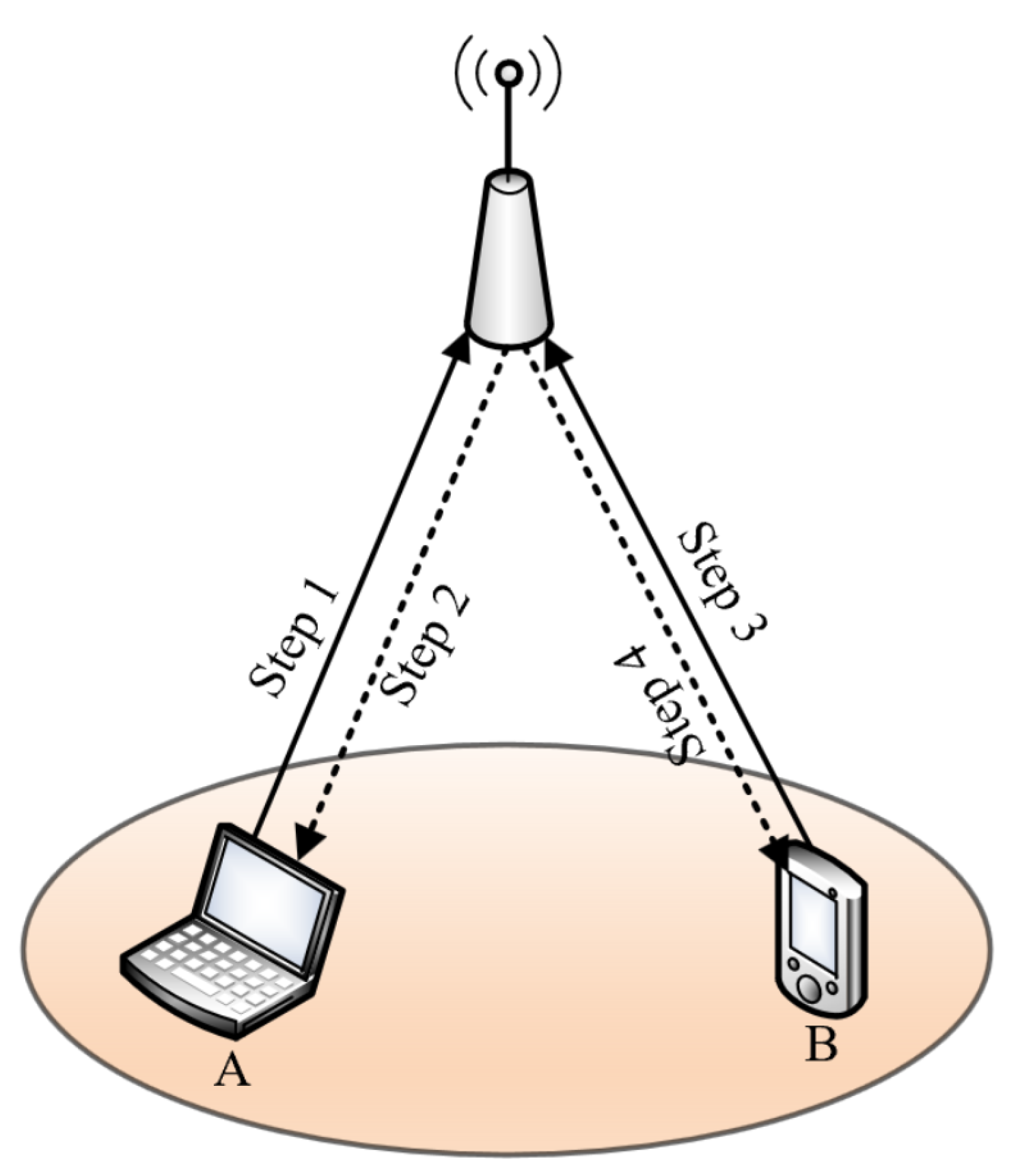
The core of our motivation is captured by the scenario illustrated in Figure 1. Here, we contrast the decision-making logic of a simple interference-aware protocol with that of a more sophisticated protocol that also considers service demands. Let us assume node A’s uplink transmission creates varying levels of interference for potential downlink recipients, with the impact ordered as I A B > I A C > I A D . Concurrently, the nodes have different service priorities, with node C requiring immediate, high-quality service (e.g., for real-time gaming) compared to nodes B and D (e.g., performing background file downloads), denoted as D C > D D > D B .
In this context, a protocol engineered solely for interference minimization would, after establishing the A→AP uplink, invariably select the AP→D downlink path to ensure the cleanest possible transmission. In contrast, a protocol co-designed for interference and demand awareness would recognize the high-priority needs of node C and select the AP→C downlink. This choice intelligently trades a marginal increase in manageable interference for the crucial fulfillment of a stringent QoS requirement. However, a critical review of the literature reveals a significant fragmentation in existing research. Current FD MAC protocols tend to focus on solving only one of these problems in isolation. On one hand, there are protocols that excel at interference cancellation or avoidance but are largely agnostic to the diverse QoS needs of the nodes. On the other hand, QoS-aware protocols often oversimplify interference models, failing to perform well in realistic, dense deployment scenarios. This fragmented approach represents a major gap, as optimizing for one objective can inadvertently degrade performance in the other.
Consider a typical smart factory scenario: a critical sensor (a UD node) needs to upload an urgent alert with low latency, while a nearby engineer uses an AR headset (a DD node) for maintenance instructions. An interference-focused protocol might aggressively silence the AR headset’s downlink to protect the sensor’s uplink, violating the engineer’s QoS requirement for a smooth video stream. Conversely, a simple QoS-aware protocol might grant both nodes access without effectively managing their mutual interference, leading to packet collisions and retransmissions for both. This demonstrates that treating interference and QoS as separate issues is untenable. A truly effective solution must manage them jointly.
This scenario crystallizes the two central technical hurdles that our proposed Interference- and Demand-Aware FD MAC (IDA-FDMAC) protocol is designed to overcome:
  • What is an effective and low-overhead method for a terminal to communicate its dynamic QoS profile to the AP? We address this by defining the QoS profile as a 2-bit configuration, embedded in control frames, that classifies nodes as either uplink-dominant (UD) or downlink-dominant (DD) based on their primary traffic needs.
  • What scheduling intelligence is required at the AP to optimally balance the dual objectives of satisfying diverse QoS contracts and maintaining network-wide interference below acceptable thresholds?

1.2. Contributions

Within a fully enabled full-duplex (FD) Internet of Things (IoT) network, Quality of Service (QoS) requirements can be broadly classified. This paper distinguishes between intra-node QoS, which pertains to the specific uplink and downlink service needs of an individual device, and inter-node QoS, which governs the relative service priorities among a group of devices. Our primary objective here is to engineer a protocol that effectively mitigates inter-node interference while ensuring the fulfillment of intra-node QoS guarantees. We also discuss how the proposed framework could be adapted for inter-node QoS scenarios. The principal contributions of this work are as follows.
  • A Novel Interference- and Demand-Aware MAC Protocol: We propose a novel Interference- and Demand-Aware Full-Duplex MAC (IDA-FDMAC) framework that, for the first time, unifies the management of inter-node interference and diverse QoS demands. To achieve this, we design a novel dual-phase contention mechanism with dynamic priority scheduling. This core mechanism resolves the inherent conflict between the two objectives: the first phase efficiently resolves contention and mitigates primary interference, while the second leverages nodes’ QoS configurations (UD/DD) to perform demand-aware resource allocation.
  • A Comprehensive Analytical Framework: For a rigorous assessment of the protocol’s capabilities, we construct a detailed theoretical model. This analytical framework is designed to jointly capture the effects of interference constraints and heterogeneous QoS demands. It enables the precise calculation of the success probability for the dual-phase contention process and the subsequent derivation of the total system throughput, while explicitly accounting for the unique characteristics of FD operation and the dynamic priority system.
  • Extensive Performance Validation: The practical efficacy of the IDA-FDMAC protocol and the fidelity of our mathematical analysis are substantiated through extensive simulation campaigns. When benchmarked against comparable protocols, the results confirm that our solution achieves a marked improvement in overall system throughput and successfully delivers on the differentiated QoS objectives for various types of nodes.
The remainder of this paper is structured as follows. Section 2 reviews the existing body of work on interference-centric FD MAC protocols and QoS provisioning. Section 3 presents the proposed IDA-FDMAC protocol, detailing both its high-level design framework and its operational mechanics. Section 4 is dedicated to the mathematical analysis of its throughput performance. In Section 5, we assess the system’s performance through simulation, and finally, Section 6 concludes this paper.

2. Related Works

To contextualize our contribution, we survey the literature on full-duplex (FD) MAC protocols. As motivated in Section 1, a truly effective FD MAC for next-generation IoT must jointly address two challenges: complex inter-node interference and heterogeneous QoS demands. However, our review of existing research reveals a clear fragmentation, where protocols are typically designed to address one of these challenges in isolation, but not both. Therefore, we structure our analysis into these two distinct research streams to highlight this critical gap.
While the development of high-performance services for the Internet of Things (IoT) remains a vibrant area of research [21,22,23,24,25,26], the existing literature on FD MAC protocols largely concentrates on partially enabled FD networks. Our work contributes to this field by proposing an advanced protocol that, in contrast to the fragmented approaches mentioned above, introduces a unified framework conscious of both interference and demand within a fully FD network context. Below, we survey the relevant prior research across these two key domains.

2.1. FD MAC Protocols for Interference Mitigation

A significant body of research on FD MAC protocols has focused on mitigating the various forms of interference that arise in FD networks.
A substantial body of work on FD MAC protocols has focused on resolving interference issues, primarily within networks composed of an FD-capable access point and half-duplex clients [6,7,8,9,10,11,12,13]. Early designs were often centered on two-node FD scenarios, where a receiver would immediately initiate a reverse transmission to the sender upon receiving a frame, relying on self-interference cancellation (SIC) at both ends [6,7,8].
More sophisticated approaches introduced interference-aware contention mechanisms. For instance, the protocols in [9,10] allow nodes experiencing lower levels of interference to select a smaller contention window (CW), thereby giving them a higher probability of accessing the channel for FD transmissions. Other strategies have explored opportunistic scheduling. The work in [11] proposed a scheme where a receiver, lacking data for the original uplink sender, could randomly select a different node for a downlink transmission, proceeding only if the resulting interference was below a predefined threshold. Similarly, researchers in [12,13] analyzed a specific three-node FD topology where the uplink sender and downlink receiver were hidden from one another, thus naturally avoiding interference.
However, a common limitation of these interference-centric protocols is that they are largely QoS-agnostic. They typically treat all nodes as homogeneous contenders for the medium, lacking mechanisms to differentiate service based on traffic directionality (e.g., uplink-dominant vs. downlink-dominant) or other application-specific requirements. Consequently, they cannot guarantee performance for diverse IoT services.

2.2. FD MAC Protocols for QoS Provisioning

A separate stream of research has aimed to incorporate QoS support into wireless MAC protocols, with some works extending these concepts to FD networks. These protocols focus on providing service differentiation to meet the heterogeneous demands of various applications.
A parallel stream of research has investigated QoS support in FD systems, though often in a limited or application-specific capacity [14,15,16,17]. For example, studies on hybrid cellular networks with a mix of FD and HD users have aimed to satisfy each user’s minimum bandwidth requirements by optimizing time/frequency resource allocation and adjusting power levels [14,15]. Despite these advances, existing MAC protocols generally assume simplistic traffic models and lack mechanisms for QoS differentiation, which is essential in heterogeneous IoT environments. Moreover, most protocols address either SI suppression or inter-node interference avoidance in isolation, without providing a unified framework that concurrently manages interference and QoS demands [16,17].
Recent studies have underscored the potential of advanced multiple access schemes in IoT and vehicular networks [27,28], highlighting the versatility of Non-Orthogonal Multiple Access (NOMA) as a key enabler for future wireless systems. However, because NOMA is fundamentally a physical-layer technique, its direct integration into MAC-layer protocol design remains constrained.
While effective at service differentiation, these QoS-oriented protocols often rely on oversimplified interference models. They tend to neglect the complex cross-link and inter-user interference scenarios that are prevalent in dense FD deployments, assuming either perfect interference cancellation or ignoring these effects altogether. This limits their practical applicability and performance in realistic FD environments.
The preceding survey demonstrates a clear dichotomy in the existing literature. FD MAC protocols have been developed to be either proficient at interference mitigation or capable of QoS provisioning, but not both simultaneously. This fragmentation has left a critical research gap: there is no unified framework that jointly and cohesively manages both complex inter-node interference and heterogeneous QoS demands.
Our work, IDA-FDMAC, is the first to be specifically designed to bridge this gap. By integrating a dual-phase contention scheme with a demand-aware dynamic priority mechanism, our protocol provides a holistic solution that adapts to both the prevailing interference conditions and the specific QoS requirements of each node.
Our own prior work in [29] made an initial attempt but was constrained by the assumption that the AP possessed complete channel state information. This led to a rigid system where the selection of one transmission link automatically dictated the other, resulting in suboptimal interference handling and inflexible QoS support. This paper rectifies these shortcomings by proposing a truly interference- and demand-aware framework for fully FD networks. We introduce explicit mechanisms for nodes to signal their QoS requirements and for the AP to perform intelligent uplink and downlink scheduling that jointly optimizes for interference and service quality.

3. IDA-FDMAC Protocol

The proposed IDA-FDMAC protocol is designed for a network in which each node, including the access point (AP), is equipped with a single full-duplex (FD) antenna and is assigned a unique, distinguishable signature. Central to the design is the concept of intra-node Quality of Service (QoS), which is addressed by classifying nodes based on their dominant traffic direction. Devices with higher uplink requirements are designated as uplink-dominant (UD) nodes, while those with greater downlink demands are termed downlink-dominant (DD) nodes. This classification is encoded compactly within the control frames, enabling the AP to adapt scheduling priorities with minimal overhead.
In our protocol, a node’s QoS requirement is communicated to the AP via a specific QoS configuration. This is not an abstract descriptor but is physically implemented in the TX type field of the RTS-FD frame. The TX type is a 2-bit configuration designed to explicitly declare the node’s classification, which in turn signals its primary bandwidth demand. The configuration is defined by bit values (00, 01, 10, 11); by simply reading this configuration, the AP can instantly and unambiguously identify the sender’s classification and its associated bandwidth demand. This design focuses on traffic directionality—the key QoS differentiator in our target scenarios—and provides a highly efficient, low-overhead mechanism for the AP to make demand-aware scheduling decisions, unlike conventional methods that rely on complex QoS parameters. For a visual representation of the frame structure containing this field, please refer to the discussion in Section 3.2.1.
This section first presents an overview of the IDA-FDMAC protocol and then provides a comprehensive description of its design principles and operational details.

3.1. Protocol Architecture

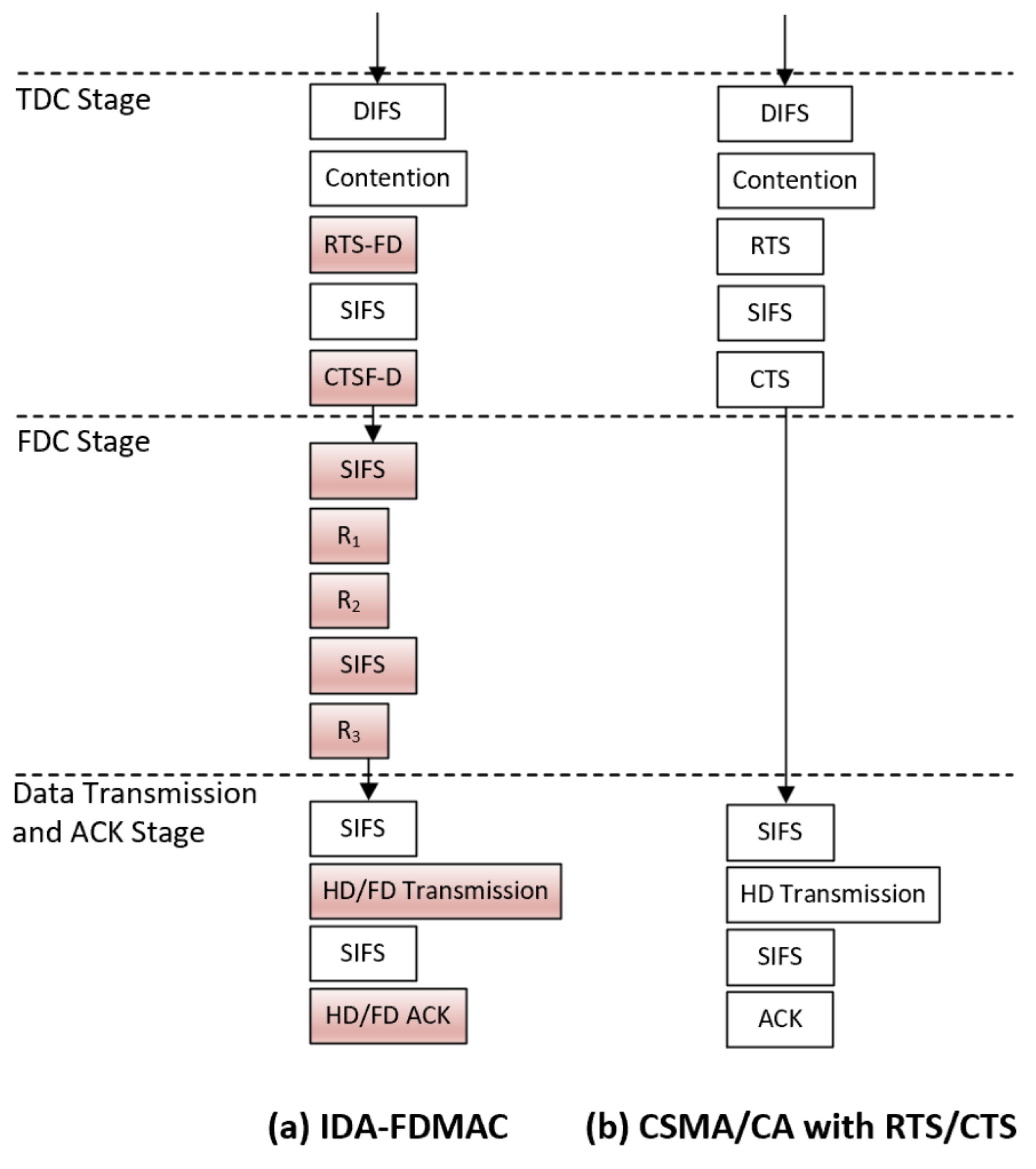
As illustrated in Figure 2, the complete IDA-FDMAC transmission sequence is an enhancement of the conventional CSMA/CA with RTS/CTS mechanism. It is architected around three distinct phases: an initial time-domain contention (TDC) phase, a subsequent frequency-domain contention (FDC) phase, and a final data transmission and ACK phase. Each phase serves a specific purpose in establishing an efficient and interference-aware full-duplex link. To clarify how this interference-aware mechanism is realized, the process is broken down across the first two phases.
The TDC phase acts as an interference-sensing and information-gathering stage. Its primary purpose is to select the first participant of the FD pair. However, the RTS-FD/CTS-FD handshake is designed to achieve more: it broadcasts crucial channel state information (CSI) across the network. This allows all non-participating nodes to overhear and calculate the potential interference their own transmissions would cause or receive, enabling them to make an informed decision about joining the contention in the next phase.
The FDC phase acts as the interference-aware selection stage. It uses the information gathered during TDC to intelligently select the second participant. This is not a simple choice of the “best” signal. For example, if an uplink transmission was established in the TDC phase, the protocol must now select a downlink receiver. To achieve this, it first filters the potential candidates, permitting only those nodes to compete whose participation would not cause disruptive interference (i.e., their estimated Signal-to-Interference Ratio is above a set threshold). Then, from this interference-vetted pool, the protocol uses its QoS-based priority rules to select the final node. This ensures the chosen transmission pairing is a joint optimization of both interference mitigation and QoS provisioning.
The TDC phase functions as the initial channel access and reservation mechanism. Its objective is to select the first participant of the FD pair—either an uplink sender if a node wins the contention or a downlink receiver if the AP wins. While the contention logic mirrors that of CSMA/CA, we have redefined the roles of the RTS and CTS frames. In our protocol, these are termed RTS-FD and CTS-FD frames. Beyond simple channel reservation, the RTS-FD frame is used by a node to signal its QoS profile (e.g., its type as UD, DD, or AP). The corresponding CTS-FD frame then serves as a network-wide broadcast, announcing which nodes are eligible to compete in the subsequent FDC phase and providing critical information for interference assessment and network synchronization.
Following a successful TDC phase, the FDC phase is initiated to select the second participant for the FD link in a collision-free manner. This phase is designed to be highly efficient and is executed through a rapid three-round (R1, R2, R3) sub-process:
  • R1 (Priority-based Candidate Selection): Eligible nodes, as determined by the preceding TDC phase and their own interference/QoS assessments, compete using a frequency-domain method inspired by the T2F rule [30,31]. A dynamic priority system is embedded here, granting nodes different contention advantages based on their node type and the context of the current transmission.
  • R2 (Signature-based Identification): All winners from R1 simultaneously transmit their unique signatures to the AP.
  • R3 (Centralized Collision Resolution): The AP, which is assumed to know all node signatures, performs cross-correlation to identify the contenders. If a single signature is detected, that node is confirmed. If multiple signatures are detected (indicating a tie in R1), the AP deterministically selects one winner, thereby guaranteeing a collision-free outcome.
Once both the uplink and downlink participants are determined, the process moves to the data transmission and ACK stage, where data and acknowledgements are exchanged concurrently over the uplink and downlink paths. Should the FDC phase not result in a pairing, the operation gracefully degrades to a standard half-duplex transmission.
Figure 3 provides a practical example of this entire sequence. A UD node (A) first wins the channel in the TDC stage. In the subsequent FDC stage, a DD node (B) is granted higher priority according to our rules (detailed in Section 3.2.2) and wins the R1 contention by selecting a lower subcarrier. After its signature is confirmed by the AP in R2 and R3, the final FD link is established. Consequently, node A begins its uplink transmission to the AP, while the AP simultaneously initiates a downlink transmission to node B.

3.2. IDA-FDMAC Design Details

This section provides a granular examination of the IDA-FDMAC protocol, sequentially detailing the operational mechanics of the time-domain contention (TDC) stage, the frequency-domain contention (FDC) stage, and the final data transmission and ACK stage. The section concludes with a discussion on the framework’s adaptability to broader Quality of Service (QoS) paradigms.

3.2.1. TDC Stage

The primary function of the TDC stage is to select the initial participant in a prospective full-duplex exchange. This stage leverages a contention mechanism analogous to the conventional CSMA/CA with RTS/CTS procedure. However, we introduce enhanced RTS-FD and CTS-FD frames that carry additional information beyond simple channel reservation.
The process begins with the AP and all nodes monitoring the channel. After sensing an idle period equivalent to a DIFS, each contender initiates a backoff timer with a random value drawn from the interval [0, CW-1], following the binary exponential backoff (BEB) algorithm. The first contender whose timer expires transmits an RTS-FD frame. A successful contention is marked by the reception of a corresponding CTS-FD frame after an SIFS interval; its absence signifies a failed attempt. This process leads to one of four distinct outcomes:
  • Case 1 (UD→AP): A UD node successfully acquires the channel, establishing itself as the uplink sender for the forthcoming FD transmission. The corresponding downlink receiver will be determined in the FDC stage.
  • Case 2 (DD→AP): This outcome is similar to Case 1, but the designated uplink sender is a DD node.
  • Case 3 (AP→UD): The AP wins the contention and addresses its RTS-FD to a specific UD node, which is then designated as the downlink receiver. The uplink sender remains to be selected via the FDC stage.
  • Case 4 (AP→DD): This case mirrors Case 3, with the distinction that the selected downlink receiver is a DD node.
The specifics of the novel RTS-FD and CTS-FD frames are detailed below.
RTS-FD frame. A key innovation within our framework is the ability of the RTS-FD frame to convey the sender’s QoS profile (i.e., its type: AP, UD node, or DD node). We achieve this by repurposing a reserved section within the standard 802.11 Frame Control field. This field contains a 2-bit ‘Type’ identifier and a 4-bit ‘Sub-Type’ identifier. By setting the ‘Type’ field to the reserved value ‘11’, we unlock the 16 unused ‘Sub-Type’ combinations. We then utilize the last two bits of the ‘Sub-Type’ field to encode the sender’s identity: ‘00’ for the AP, ‘01’ for a UD node, and ‘10’ for a DD node. This allows any receiving node to instantly recognize the sender’s type.
Beyond this new capability, the RTS-FD frame maintains its traditional function of reserving the medium by setting the Network Allocation Vector (NAV). The NAV duration is calculated to cover the entire transaction, including the TDC and FDC stages, as well as the final data and ACK exchange.
CTS-FD frame. The CTS-FD frame is engineered to perform three critical functions in addition to confirming the channel reservation. It announces (1) the nature of the current TDC transmission, (2) the set of nodes eligible to compete in the subsequent FDC stage, and (3) the interference characteristics measured between the RTS and CTS sender.
As shown in Figure 4, the CTS-FD frame augments the legacy CTS structure with three new fields, TX type, bitmap, and channel state information (CSI), each corresponding to one of the new functions.
TX type. A unique two-bit code is assigned to each of the four TDC transmission cases, as specified in Table 1. The CTS sender determines the current case—either by inspecting the received RTS-FD if it is the AP or based on its own node type if it is a UD/DD node—and embeds the corresponding code into the TX type field. This allows all overhearing nodes to understand the context of the ongoing transmission.
Bitmap. The CTS sender employs a bitmap [32] to explicitly authorize nodes for participation in the FDC stage. A ‘1’ in the i-th position of the map grants permission to the i-th node, while a ‘0’ denies it. The bitmap’s configuration depends on the context. In Cases 1 or 2, the AP (as the CTS sender) sets the i-th bit to ‘1’ only if it has pending data for node i and the transmission time fits within the NAV. In Cases 3 or 4, the node (as the CTS sender) sets all bits to ‘1’, effectively opening the FDC contention to any node that has data for the AP. We allocate 6 Bytes for the bitmap, sufficient to manage up to 48 nodes.
CSI. This field contains the measured channel state information between the original RTS sender and the current CTS sender, derived from the received power of the RTS-FD frame. By broadcasting this value, the CTS sender enables all other nodes to predict whether their potential transmissions would cause harmful interference during the data exchange phase. The overhead for this CSI acquisition is minimal because the required information is piggybacked onto the existing CTS-FD frame, avoiding a costly dedicated signaling phase. The transmission time for these few extra bytes is on the order of microseconds, which is negligible compared to the millisecond-scale duration of a typical data packet. Therefore, the incremental time and energy cost is insignificant, ensuring the benefits of interference-aware scheduling are achieved without impacting overall network efficiency.

3.2.2. FDC Stage

Upon completion of the TDC stage, the FDC stage is initiated to select the second member of the FD pair. This highly efficient contention process is designed to be entirely collision-free and is executed in three distinct rounds (R1, R2, and R3).
FDC contention in R1. In R1, nodes that are eligible to participate engage in a priority-based frequency contention.
Contention conditions. A node’s eligibility to contend in the FDC stage is context-dependent.
If the TDC stage resulted in Case 1 or 2 (i.e., the uplink sender is known), the FDC stage aims to select a downlink receiver. If node i is the confirmed uplink sender, another node j is permitted to contend if it meets two criteria: (1) its corresponding bit in the CTS-FD’s bitmap is set to ’1’ and (2) its Signal-to-Interference Ratio ( S I R j ) must be above a threshold γ , ensuring its reception will not be compromised by node i’s uplink transmission. The S I R j is calculated differently for two-node FD (where j = i ) and three-node FD (where j i ). For the two-node case, after applying SIC, the residual self-interference is considered, as shown in Equation (1). For the three-node case, the non-self-interference from node i is the dominant factor, as expressed in Equation (2). In both cases, node j can estimate the necessary channel coefficients from the received RTS-FD and CTS-FD frames.
If the TDC stage resulted in Case 3 or 4 (i.e., the downlink receiver is known), the FDC stage selects an uplink sender. If node j is the confirmed downlink receiver, another node i is eligible to contend if it meets three criteria: (1) it has data queued for the AP, (2) its required transmission time does not exceed the NAV, and (3) it calculates that its transmission will not disrupt reception at node j (i.e., S I R j > γ ). Node i can perform this calculation using channel information gleaned from the CTS-FD frame sent by node j.
Priority-based contention rules. To embed QoS awareness directly into the contention mechanism, we employ a priority-based frequency contention scheme. Eligible nodes randomly select an OFDM subcarrier from a designated range and transmit a pilot signal. The node that selects the subcarrier with the lowest index wins the R1 contention.
Crucially, the range of available subcarriers is dynamically assigned based on a node’s type and the current transmission context, effectively creating different priority levels. We define three priority tiers based on three integers a , b , c , where a < b < c :
  • P r i o 0 (Highest Priority): Subcarrier selection range is [ 1 , a ] .
  • P r i o 1 (Medium Priority): Subcarrier selection range is [ 1 , b ] .
  • P r i o 2 (Lowest Priority): Subcarrier selection range is [ 1 , c ] .
The dynamic priority assignments are defined as follows:
  • When a UD node wins TDC (Case 1: UD→AP): The highest priority ( P r i o 0 ) is given to DD nodes, as they have the most urgent need for a downlink slot. The current UD node (the TDC winner) is given medium priority ( P r i o 1 ) to potentially form a two-node FD link. Other UD nodes receive the lowest priority ( P r i o 2 ).
  • When a DD node wins TDC (Case 2: DD→AP): The current DD node receives the highest priority ( P r i o 0 ) to satisfy its own downlink demand. Other DD nodes have medium priority ( P r i o 1 ), while all UD nodes have the lowest priority ( P r i o 2 ).
  • When AP targets a UD node (Case 3: AP→UD): The targeted UD node has the highest priority ( P r i o 0 ) to find an uplink partner. Other UD nodes have medium priority ( P r i o 1 ), and DD nodes have the lowest priority ( P r i o 2 ).
  • When AP targets a DD node (Case 4: AP→DD): The highest priority ( P r i o 0 ) is assigned to UD nodes, as this creates a highly efficient FD pairing. The targeted DD node has medium priority ( P r i o 1 ), while other DD nodes are given the lowest priority ( P r i o 2 ).
Signature-assisted contention in R2. Following the methodology of [33,34], we assume each node has a unique signature known to the AP. In R2, all winning node(s) from the R1 contention simultaneously transmit their respective signatures across the entire channel. The AP employs a bank of correlators to detect the received signatures. By calculating the correlation value for each known signature, as shown in Equation (3), the AP can reliably identify all contenders from R1, even if they transmitted concurrently. We adopt a signature length of 10 bytes, consistent with prior work [33].
Collision resolution in R3. The R3 phase is a deterministic, centralized decision-making step performed by the AP. Based on the outcome of the signature detection in R2, the AP resolves any potential ties from R1. If only a single signature was detected, it signifies a clear winner from R1. The AP simply broadcasts this signature back to the network, confirming the selection. If multiple signatures were detected, indicating that several nodes chose the same lowest-indexed subcarrier in R1, the AP randomly selects one of the detected signatures and broadcasts it. This centralized resolution guarantees that only one node is ultimately selected, completely eliminating collisions from the FDC stage and maximizing contention efficiency.
The rationale behind the contention design. The choice to structure our protocol with a TDC stage followed by an FDC stage is deliberate, driven by the dual considerations of contention overhead and signal synchronization.
The primary motivation for incorporating an FDC stage is its exceptional efficiency. Unlike the backoff-based TDC, which can introduce significant idle time and overhead [35], the frequency-domain contention in R1 can be completed within the time of a single OFDM symbol [30]. This drastic reduction in contention time makes it an ideal choice for the second, more targeted selection phase.
Conversely, the reason for retaining a TDC stage at the beginning is its crucial role in establishing network synchronization. The fast-paced FDC stage demands precise time and frequency alignment among participants, which is challenging to achieve from a cold start. The initial RTS-FD/CTS-FD exchange in the TDC stage provides a natural and robust mechanism to synchronize all potential contenders, paving the way for a successful FDC phase.

3.2.3. Data Transmission and ACK Stage

In contrast to the sequential half-duplex (HD) transmission in standard CSMA/CA, the IDA-FDMAC protocol enables concurrent data exchange after the contention phases are complete. Once the uplink sender and downlink receiver are finalized, the data transmission and ACK stage commences. The uplink sender transmits its data to the AP, and simultaneously the AP transmits data to the designated downlink receiver. The corresponding acknowledgements can also be exchanged in parallel. In the event that no second participant is selected during the FDC stage (e.g., no nodes were eligible or chose to contend), the protocol gracefully degrades to a standard HD transmission between the single winner of the TDC stage and the AP.
In IDA-FDMAC, leveraging full-duplex technology, ACK frames are transmitted simultaneously on the uplink and downlink, mirroring the concurrent data exchange. This design minimizes signaling overhead and reduces end-to-end latency, thereby enhancing spectral efficiency. Given the short size and robust modulation of ACK frames, the probability of failure is negligible.

3.2.4. Generalization of QoS Support

The IDA-FDMAC protocol is designed as a versatile framework, capable of being adapted to support a wide array of QoS requirements beyond bandwidth, such as delay, and to handle both intra-node and inter-node QoS scenarios. The key to this adaptability lies in redefining the contention rules to align with the specific service objectives.
For different intra-node QoS metrics, the core contention logic remains unchanged. One only needs to redefine the UD and DD classifications. For example, to support delay-sensitive applications, a node with a stricter uplink delay requirement could be classified as a UD node, while one with a stricter downlink delay requirement would be a DD node. These nodes would then compete for channel access using the priority rules already outlined.
To support inter-node QoS, a more fundamental adjustment to the contention rules is necessary. This involves integrating established QoS-aware mechanisms directly into both contention stages. For instance, the TDC stage’s backoff mechanism could be replaced with the Enhanced Distributed Channel Access (EDCA) scheme from 802.11e [36], while the FDC stage’s R1 contention could be replaced with a weighted frequency-domain scheme like WT2F [37]. In this configuration, the UD/DD classification becomes obsolete, as QoS is managed on a per-node, inter-network basis. A node with a high uplink bandwidth requirement would be assigned a high-priority EDCA access category to increase its chances of winning the TDC stage, while a node with high downlink needs would be given a higher weight (a smaller subcarrier range) in the WT2F scheme to enhance its probability of winning the FDC stage. This approach allows for fine-grained resource allocation that directly maps to the collective needs of all nodes in the network.

4. Performance Analysis

In this section, we develop a mathematical model to analyze the performance of the IDA-FDMAC protocol. Our analysis considers a saturated network scenario, which assumes that every node perpetually has data to transmit. The network consists of a single access point (AP), designated as node 0, along with N uplink-dominant (UD) nodes (nodes 1 to N) and M downlink-dominant (DD) nodes (nodes N + 1 to N + M ). The analysis will proceed by first modeling the time-domain contention (TDC) and frequency-domain contention (FDC) stages and then deriving the throughput for each node.

4.1. Analysis of the TDC Stage

We model the contention process in the TDC stage using a framework inspired by the well-established Bianchi model [38,39,40]. The core of this model is the concept of a generic time slot, Ω , which represents the duration corresponding to a single decrement of a node’s backoff counter. The length of this slot is variable and depends on the channel’s state, which can be idle, successful transmission, or collision. We can characterize Ω as follows:
σ , with probability P e = i = 0 N + M ( 1 β i ) T s , with probability P s i = β i j i N + M ( 1 β j ) , j [ 0 , N + M ] T c , with probability P c = 1 P e i = 0 N + M P s i
Here, β i is the attempt rate of node i, representing the probability that node i transmits an RTS-FD frame in a given slot. The duration σ corresponds to an empty slot time. T s is the total time consumed by a successful transmission cycle initiated by a single winner in the TDC stage, while T c is the time wasted in a collision where multiple nodes transmit simultaneously. Based on the protocol sequence in Figure 2, T s and T c are given by
T s = DIFS + RTS + 5 SIFS + CTS + k = 1 3 T R k + T DATA + ACK
T c = DIFS + RTS + SIFS + CTS
In Equation (5), T R k is the duration of the k-th round of the FDC stage, and T DATA is the time for the final data exchange.
The probabilities in Equation (4) are defined as follows:
  • P e is the probability that the channel remains idle, with no node attempting a transmission.
  • P s i is the success probability for node i, where only node i transmits. For the AP (node 0), this is an aggregate probability, P s 0 = i = 1 N + M P s 0 i , where P s 0 i is the probability of the AP successfully sending an RTS-FD to node i, calculated as follows:
    P s 0 i = β 0 i j = 1 N + M ( 1 β j ) , i [ 1 , N + M ]
    Here, β 0 i is the AP’s attempt rate towards node i, and the total attempt rate for the AP is β 0 = i = 1 N + M β 0 i .
  • P c is the collision probability, occurring when two or more nodes transmit in the same slot.
From this, the expected duration of a generic slot, E ( Ω ) , can be calculated as the weighted average of these outcomes:
E ( Ω ) = σ P e + T s i = 0 N + M P s i + T c P c
Remark: The attempt rate β i is a function of the contention window parameters. As derived in [38], for a system with a maximum backoff stage m and minimum contention window C W m i n , i , the relationship is:
p i = 1 j i , j = 0 N + M 1 β j β i = 2 1 2 p i 1 2 p i C W m i n , i + 1 + p i C W m i n , i 1 2 p i m
where p i is the collision probability as seen by node i. For the simplified case where the backoff stage is not used ( m = 0 ), the equation reduces to the well-known form from [38,41]:
β i = 2 C W i + 1

4.2. Analysis of the FDC Stage

The FDC stage serves to select the second participant for the FD transmission. A node that meets the eligibility criteria will compete according to the priority rules, as detailed in Section 3.2.2. A node can win this stage in one of two ways: (1) it is the sole winner of the R1 contention, or (2) it is chosen by the AP in R3 after a collision in R1. To illustrate the analysis, we will focus on Case 1, where a UD node i has already won the TDC stage. The methodology for the other cases is analogous.
Figure 5 depicts the priority-based subcarrier allocation for this scenario. DD nodes are given the highest priority (range [ 1 , a ] ), the current UD node i has medium priority (range [ 1 , b ] ), and all other UD nodes have the lowest priority (range [ 1 , c ] ).
Let P U D A P i ( j ) denote the probability that node j is selected as the downlink receiver, given that UD node i is the uplink sender. This probability is the sum of two disjoint events:
P U D A P i ( j ) = P U D A P i , s u c ( j ) + P U D A P i , c o l ( j ) , j [ 1 , N + M ]
where P U D A P i , s u c ( j ) is the probability that node j is the unique winner of the R1 contention, and P U D A P i , c o l ( j ) is the probability that node j wins after being selected by the AP from a collision in R1. For simplicity, we follow the assumption in [31] that collisions involve only two nodes, as multi-node collisions are rare.
We now derive these probabilities for the different types of nodes that can be selected as the downlink receiver.
When the current UD node j (where j = i ) is selected, the probabilities of unique success and collision-resolved success are
P U D A P i , s u c ( j ) = k = 1 a 1 1 b P a S i D D P c S i U D 1
P U D A P i , c o l ( j ) = 1 2 k = 1 a 1 1 b [ 1 a | S i D D | 1 P a | S i D D | 1 P c | S i U D | 1 + 1 c | S i U D | 1 1 P a | S i D D | P c | S i U D | 2 ]
Here, S i U D and S i D D are the sets of eligible UD and DD nodes, respectively. The logic behind (12) is that for node i to win by selecting subcarrier k [ 1 , a 1 ] , all eligible DD nodes must select subcarriers above k, and all other eligible UD nodes must also select subcarriers above k. Equation (13) accounts for the two scenarios where node i collides with either one DD node or one other UD node on subcarrier k and is subsequently chosen by the AP with probability 1/2.
When another UD node j ( j S i U D , j i ) is selected, the probabilities are
p U D A P i , s u c ( j ) = k = 1 a 1 1 c P a | S i D D | P b P c | S i U D | 2
p U D A P i , c o l ( j ) = 1 2 k = 1 a 1 1 c [ 1 b P a | S i D D | P c | S i U D | 2 + 1 a | S i D D | 1 P a | S i D D | 1 P b P c | S i U D | 2 + 1 c | S i U D | 2 1 P a | S i D D | × P b P c | S i U D | 3 ]
When a DD node j ( j S i D D ) is selected, the probabilities are
P U D A P i , s u c ( j ) = k = 1 a 1 1 a P a | S i D D | 1 P b P c | S i U D | 1
P U D A P i , c o l ( j ) = 1 2 k = 1 a 1 1 a [ 1 b P a S i D D 1 P c S i U D 1 + 1 a | S i D D | 1 1 P a | S i D D | 2 P b P c | S i U D | 1 + 1 c | S i U D | 1 1 P a | S i D D | 1 × P b P c | S i U D | 2 ]
The analyses for the other three initial cases (Case 2, 3, and 4) follow the same probabilistic logic, accounting for their respective priority assignments. Let P D D A P i ( j ) , P A P U D i ( j ) , and P A P D D i ( j ) be the probabilities of selecting node j in the FDC stage for these respective initial cases. Each can be similarly decomposed:
P D D A P i ( j ) = P D D A P i , s u c ( j ) + P D D A P i , c o l ( j ) , j [ 1 , N + M ]
P A P U D i ( j ) = P A P U D i , s u c ( j ) + P A P U D i , c o l ( j ) , j [ 1 , N + M ]
P A P D D i ( j ) = P A P D D i , s u c ( j ) + P A P D D i , c o l ( j ) , j [ 1 , N + M ]
The detailed derivations for each term in Equations (18)–(20) are provided in Appendix A.

4.3. Throughput Expression

With the probabilistic models for both contention stages established, we can now formulate the expressions for per-node and system throughput. Throughput is defined as the number of successfully delivered data bits per unit of time, which we normalize by the duration of an average generic slot, E ( Ω ) .
An uplink transmission from node i ( 1 i N + M ) to the AP can occur under two distinct conditions:
  • Node i wins the TDC stage, thereby becoming the designated uplink sender.
  • Another node (or the AP) wins the TDC stage, and node i subsequently wins the FDC stage to become the uplink sender.
The uplink throughput for node i, denoted as Γ n o d e i , is therefore
Γ n o d e i = s E ( Ω ) [ P s i + j = 1 N P s 0 j P A P U D j ( i ) + j = N + 1 N + M P s 0 j P A P D D j ( i ) ]
where s is the payload size in bits.
Similarly, a downlink transmission from the AP to node i can happen if the following occur:
  • The AP wins the TDC stage and selects node i as the designated downlink receiver.
  • Another node wins the TDC stage, and node i subsequently wins the FDC stage to become the downlink receiver.
The downlink throughput to node i, denoted as Γ A P i , is given by
Γ A P i = s E ( Ω ) P s 0 i + j = 1 N P s j P U D A P j ( i ) + j = N + 1 N + M P s j P D D A P j ( i )
Finally, the total system throughput, Γ , is the sum of all successful uplink and downlink transmissions across the entire network:
Γ = i = 1 N + M Γ n o d e i + i = 1 N + M Γ A P i

5. Performance Evaluation

In this section, we rigorously evaluate the performance of the proposed IDA-FDMAC protocol. The evaluation is conducted using a custom C++ simulator developed in our prior research [29,37,42]. We first validate the protocol’s internal mechanisms and the accuracy of our analytical model and then benchmark its performance against the interference-based FD protocol from [9] and the standard half-duplex CSMA/CA protocol.
The simulation environment models a single cell containing one AP, three UD nodes (UD1, UD2, and UD3), and three DD nodes (DD4, DD5, and DD6). The nodes are randomly positioned around the AP, as depicted in the network topology in Figure 6. The key parameters used for the simulation, such as frame sizes and timing values detailed in Table 2, are based on the IEEE 802.11g standard [32] to ensure alignment with common practice. Each simulation is executed for a total duration of 200 seconds to ensure statistically stable results. For clarity in the subsequent plots, analytical results derived from our model in Section 5 are labeled with the prefix “ana_”, while results obtained from the simulation are labeled with “sim_”.

5.1. Validation of the Proposed IDA-FDMAC Protocol

This subsection assesses the core functionality of IDA-FDMAC: its ability to provide differentiated services by tuning the priority values ( a , b , c ) . The network topology from Figure 6 is configured such that adjacent nodes create significant interference, meaning if one node wins the TDC stage, its immediate neighbors are disqualified from the FDC stage ( S I R < γ ). To ensure a fair balance between uplink and downlink opportunities, the AP’s attempt rate is set to β 0 = ( N + M ) β i , where β i is the uniform attempt rate for all other nodes [43]. The results are presented in Figure 7.
Figure 7a examines the throughput for a typical UD node. Several key observations can be made. First, the simulation curves ( s i m _ u p l i n k and s i m _ d o w n l i n k ) exhibit a tight correspondence with the analytical predictions ( a n a _ u p l i n k and a n a _ d o w n l i n k ), validating the high fidelity of our theoretical model. Second, for any given priority setting, throughput declines as the contention window (CW) increases, a direct result of the lower attempt rates and increased TDC overhead. Most importantly, the impact of the priority mechanism is clear. When priorities are uniform (e.g., (10,10,10) or (50,50,50)), uplink and downlink throughputs are nearly identical, as the QoS differentiation is effectively disabled. However, with the non-uniform setting of (10,30,50), a significant performance gap emerges: the uplink throughput (declining from 5.1202 Mbps to 3.8668 Mbps) consistently and substantially exceeds the downlink throughput (from 2.5914 Mbps to 2.0064 Mbps). This result unequivocally demonstrates the protocol’s ability to allocate resources in favor of a UD node’s primary requirement.
Figure 7b presents the corresponding analysis for a DD node. The results largely mirror the previous findings, but with a crucial reversal in the differentiated service case. With priorities set to (10,30,50), the downlink throughput (ranging from 5.2445 Mbps down to 3.8948 Mbps) is now consistently higher than the uplink throughput (from 2.7699 Mbps to 2.0414 Mbps). This confirms that IDA-FDMAC successfully prioritizes downlink resources for DD nodes, fulfilling their specific QoS needs.
Figure 7c evaluates the total system throughput. The close match between simulation and analytical curves again confirms our model’s accuracy. The plot also reveals that throughput is maximized with larger priority ranges (e.g., (50,50,50)) because a wider subcarrier selection space in the FDC stage reduces the probability of collisions, thereby enhancing overall contention efficiency.

5.2. Comparison Among the Proposed IDA-FDMAC Protocol, the Full-Duplex Protocol in Ref. [9], and CSMA/CA

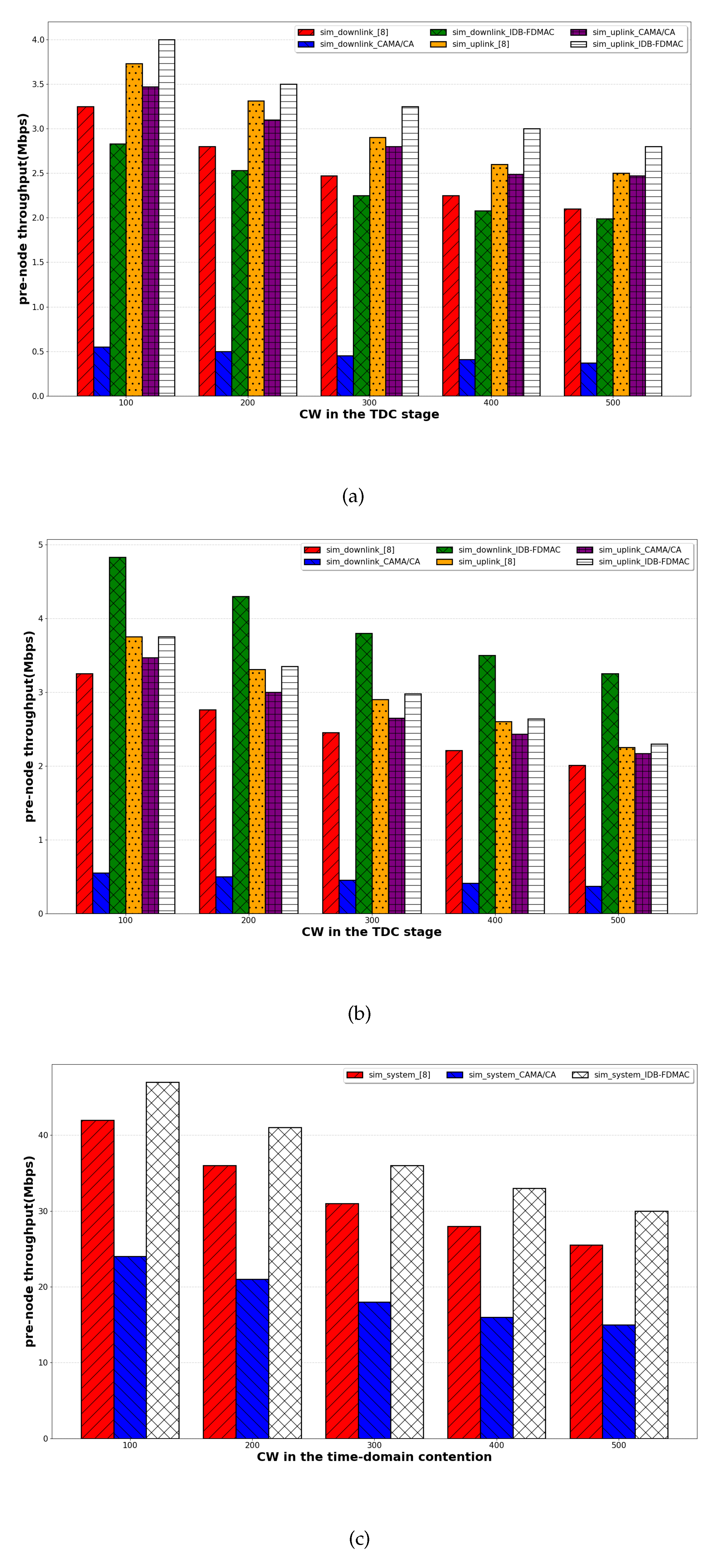
In this subsection, we benchmark IDA-FDMAC against an existing interference-aware FD protocol [9] and the standard HD CSMA/CA. To ensure a fair comparison with these protocols that only support HD nodes, we modify our protocol to prevent a TDC winner from also participating in the FDC stage (disabling the two-node FD case). We adopt the same priority values as in [9], setting (a,b,c) to (8,12,16), and use an identical attempt rate for all nodes and the AP. The comparative results are shown in Figure 8.
Figure 8a,b highlight the unique QoS-aware capabilities of our protocol. IDA-FDMAC successfully delivers differentiated service, providing UD nodes with higher uplink throughput and DD nodes with higher downlink throughput. In stark contrast, both the protocol from ref. [9] and CSMA/CA exhibit an inherent bias towards uplink traffic, where uplink throughput is always greater than downlink, irrespective of node type. This is particularly detrimental for a DD node, as seen in Figure 8b, where its primary service requirement for downlink capacity is unmet. This discrepancy arises because these competing protocols are designed to be interference-aware only, lacking any mechanism to sense or adapt to the QoS demands of the nodes.
Figure 8c compares the aggregate system throughput. Our IDA-FDMAC protocol demonstrates a significant performance advantage, achieving on average a 95.03% improvement over CSMA/CA and a 15.04% improvement over the protocol from ref. [9]. This superiority stems from three fundamental design efficiencies. First, IDA-FDMAC allows both nodes and the AP to initiate transmissions, creating four possible FD scenarios, whereas the protocol in ref. [9] is limited to node-initiated transmissions only. Second, our use of a highly efficient FDC stage to select the second node is significantly faster than the time-domain contention used for the same purpose in ref. [9]. Third, our signature-based collision resolution in the FDC stage completely eliminates collisions for the second-node selection, a feature absent in the competing protocol. These combined factors confirm that IDA-FDMAC not only provides QoS but also boosts overall network throughput.
In summary, the comprehensive simulation results validate the accuracy of our theoretical model and demonstrate that our integrated approach to managing both interference and QoS requirements allows IDA-FDMAC to outperform existing related protocols.

5.3. Performance Under Non-Saturated Conditions

To evaluate the protocol’s performance in realistic deployment scenarios, we extend our investigation to non-saturated traffic conditions. While the saturated model is valuable for theoretical analysis and deriving upper-bound performance, real-world Internet of Things (IoT) networks typically experience sporadic and variable traffic loads. This section presents simulation results that demonstrate the robustness and effectiveness of the IDA-FDMAC protocol under such dynamic conditions.

5.3.1. Simulation Setup for Non-Saturated Traffic

To model a non-saturated environment, we depart from the assumption of persistently backlogged queues. Instead, the packet generation process at each node is modeled as an independent Poisson arrival process. We introduce a normalized “Load Factor” to control the network traffic intensity, varying from 0.1 (lightly loaded) to 1.0 (heavily loaded, approaching saturation). This factor directly scales the mean packet arrival rate ( λ ) for each node. To ensure a fair comparison, all other simulation parameters, including the network topology and the timing values from Table 2, remain unchanged.

5.3.2. Analysis of System Throughput

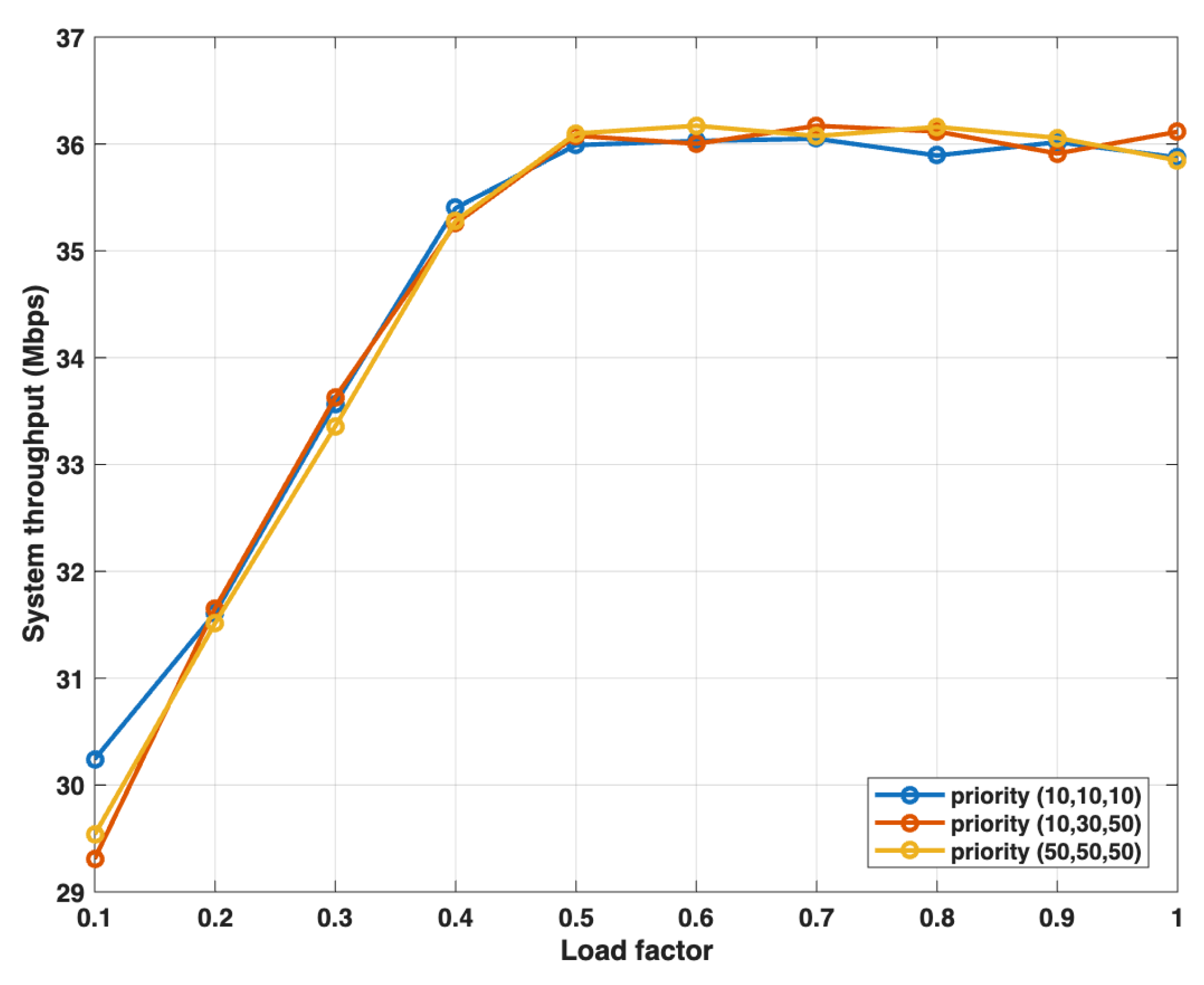
Figure 9 illustrates the total system throughput under varying load factors for three distinct priority configurations: uniform high priority ((10,10,10)), differentiated priority ((10,30,50)), and uniform low priority ((50,50,50)). As expected, the system throughput for all configurations increases as the load factor grows, since more data becomes available for transmission. A key observation from Figure 9 is that the three throughput curves are closely aligned. This result indicates that our proposed priority-based QoS mechanism operates with high efficiency, successfully reallocating transmission opportunities to service higher-priority nodes without introducing significant system overhead or sacrificing overall network capacity. This confirms that the QoS differentiation capability of the IDA-FDMAC protocol does not come at the expense of total system performance.

5.3.3. Analysis of QoS Differentiation

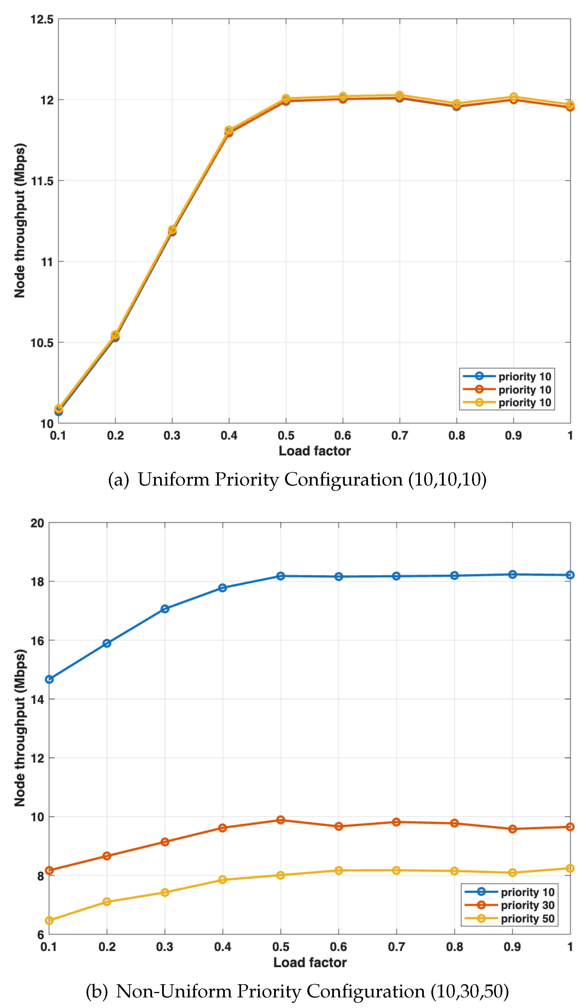
This section aims to verify that the protocol’s QoS differentiation capability remains effective across the entire spectrum of traffic loads. Figure 10a presents the baseline performance under a uniform high-priority configuration of (10,10,10). In this scenario, nodes with different QoS requirements achieve nearly identical throughput, which confirms fair resource allocation when priorities are not differentiated. For instance, at a load factor of 0.2, the throughputs for the high-, medium-, and low-priority nodes are all clustered around 10.55 Mbps. The throughput for all nodes increases steadily as the load factor grows from 0.1 to 0.5. Beyond a load factor of 0.5, the curves begin to flatten, and the throughput stabilizes at approximately 12 Mbps as the network approaches saturation.
In stark contrast, Figure 10b showcases the performance with a non-uniform priority setting of (10,30,50). The results clearly and consistently demonstrate the efficacy of our protocol: the node assigned the highest priority (contention range [1, 10]) achieves substantially higher throughput than the nodes with medium ([1, 30]) and low ([1, 50]) priorities. Crucially, this distinct performance stratification is maintained across all load factors, from light (0.1) to heavy (1.0). For example, at a load factor of 0.6, the high-priority node achieves a throughput of approximately 18 Mbps, significantly outperforming the medium-priority node at 9.8 Mbps and the low-priority node at 8.2 Mbps. Crucially, this clear performance gap is maintained across all load factors, from light (0.1) to heavy (1.0). These simulation results empirically validate that the IDA-FDMAC protocol is not only robust under realistic, non-saturated conditions but also successfully delivers predictable and differentiated QoS according to pre-configured priorities. This confirms its suitability for practical IoT applications with heterogeneous service requirements.

5.4. Scalability Analysis with Increasing Network Size

To provide a more comprehensive evaluation and assess the protocol’s performance as the network density grows, we extended our theoretical model from Section 4 and conducted a corresponding set of new simulations. For this analysis, we revert to the saturated traffic model to isolate the effect of network size on the fundamental contention mechanics. We analyzed a range of symmetric network topologies, starting from 5 nodes and scaling up to 30 nodes (i.e., from 2 UD + 2 DD + AP to 14 UD + 14 DD + AP). The results of this scalability analysis are presented in Figure 11. The figure plots the total system throughput against the number of nodes in the network, comparing the predictions from our analytical model with the results obtained from the C++ simulator. Several key insights can be drawn:
  • Excellent Model–Simulation Agreement: There is a very close match between the analytical curve and the simulation data points across the entire range of network sizes. For instance, at 15 nodes, the analytical model predicts a throughput of 42.65 Mbps, while the simulation yields a result of 42.58 Mbps, demonstrating a negligible deviation. This consistency validates the accuracy of our theoretical model in predicting the protocol’s performance, even in larger-scale scenarios.
  • Graceful Throughput Scaling: The system throughput initially increases as more nodes are added to the network. For example, as the number of nodes increases from 5 to 15, the total system throughput rises significantly from approximately 32.3 Mbps to 42.5 Mbps. This is because a higher number of active nodes increases the probability of successful channel access and the formation of efficient full-duplex pairs, leading to better overall channel utilization.
  • Contention Impact in Dense Networks: As the number of nodes continues to increase beyond an optimal point (around 44 Mbps with 25 nodes in this configuration), the system throughput begins to saturate. This behavior is expected and is attributable to the rising probability of collisions in the time-domain contention (TDC) stage. Increased contention leads to longer backoff periods and more time spent on collision resolution, which slightly diminishes the gains from having more transmission opportunities.
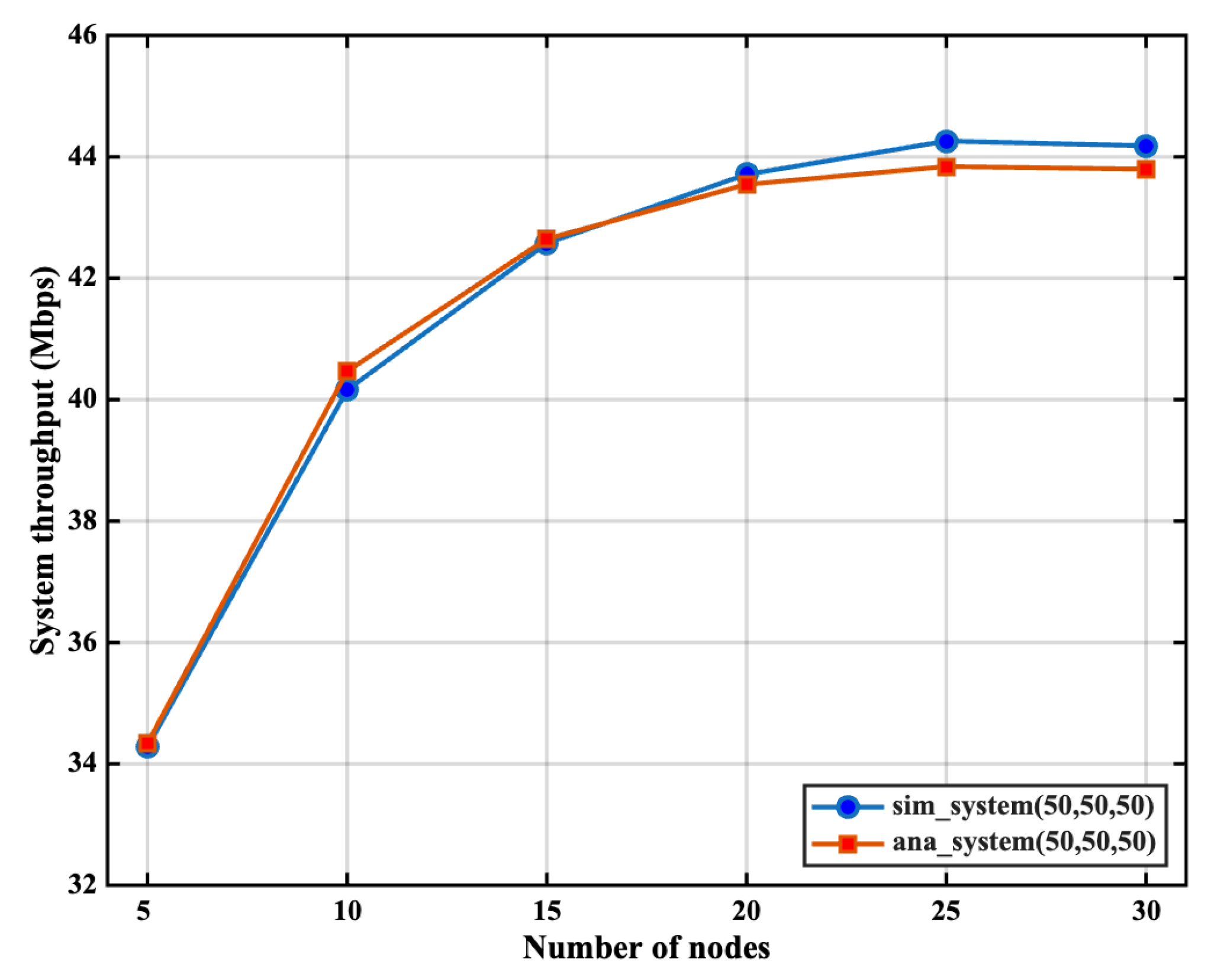
Overall, the results confirm that the IDA-FDMAC protocol is robust and scales effectively, handling a growing number of devices without a sudden degradation in performance.
Figure 11. Theoretical analysis vs. simulation results for an increasing number of nodes.
Electronics 14 03901 g011

6. Conclusions

This paper has introduced IDA-FDMAC, a novel MAC layer framework engineered to unlock the potential of full-duplex communication in modern IoT networks by concurrently addressing the twin challenges of interference mitigation and Quality of Service provisioning. Our contribution is twofold: we first constructed a comprehensive mathematical model to analytically predict the protocol’s behavior and then substantiated these theoretical findings through rigorous, scenario-based simulations. The close alignment between our analytical and simulated results serves as a strong validation, confirming both the practical viability of the IDA-FDMAC design and the high fidelity of our performance model.
As such, this research provides a foundational building block for the design of next-generation MAC protocols capable of fully harnessing the spectral efficiency gains promised by FD technology. Looking ahead, while the current investigation has been confined to a single-cell topology, the logical next step is to extend this framework to the more complex and realistic multi-cell environment. Future research will therefore focus on developing new interference- and demand-aware FD MAC protocols tailored for these scenarios, where inter-cell interference becomes a dominant factor, and conducting a thorough performance analysis of their effectiveness. In addition, extending IDA-FDMAC with NOMA techniques represents a promising avenue to further enhance efficiency and security in dense network deployments.

Author Contributions

Conceptualization, L.T.; methodology, Z.L.; software, S.Q.; writing—original draft, L.T. and Z.L.; writing—review and editing, S.Q. and Q.Z. All authors have read and agreed to the published version of the manuscript.

Funding

This work was supported in part by Guangdong Province Key Discipline Research Capacity Enhancement Project under Grant 2022ZDJS146, in part by Guangdong Provincial Key Laboratory of Kunpeng and Intelligent Manufacturing under Grant 2023KSYS012, in part by Dongguan AIoT Edge Computing Engineering Technology Research Center, in part by Guangzhou Nansha Science and Technology Planning Project (File no. 2024ZD001 and 2023ZD002), and in part by Guangzhou Huangpu International Science and Technology Cooperation Project (File no. 2023GH03).

Data Availability Statement

The original contributions presented in this study are included in the article. Further inquiries can be directed to the corresponding author.

Conflicts of Interest

The authors declare no conflicts of interest.

Appendix A

In this Appendix, we provide a detailed derivation for each term in Equations (18)–(20).
In (18), when j = i , meaning the current DD node i becomes the downlink receiver during the FDC stage, we have the following:
P D D A P i , s u c ( j ) = k = 1 a 1 a P b | S i D D | 1 P c | S i U D |
P D D A P i , c o l ( j ) = 1 2 k = 1 a 1 1 a 1 b | S i D D | 1 1 P b | S i D D | 2 P c | S i U D | + 1 c | S i U D | 1 P b | S i D D | 1 P c | S i U D | 1
When j S i U D , indicating that UD node j becomes the downlink receiver, we have
P D D A P i , s u c ( j ) = k = 1 a 1 1 c P b | S i D D | 1 P a P c | S i U D | 1
P D D A P i , c o l ( j ) = 1 2 k = 1 a 1 1 c [ 1 a P b | S i D D | 1 P c | S i U D | 1 + 1 b | S i D D | 1 1 P b | S i D D | 2 P a P c | S i U D | 1 + 1 c | S i U D | 1 1 P b | S i D D | 1 P a P c | S i U D | 2 ]
When j S i D D , but j i , meaning another DD node j becomes the downlink receiver, we have
P A P D D i , s u c ( j ) = k = 1 a 1 1 b P b | S i D D | 2 P a P c | S i U D |
P D D A P i , col ( j ) = 1 2 k = 1 a 1 1 b 1 a P b | S i D D | 2 P c | S i U D | + 1 b | S i D D | 2 1 P b | S i D D | 3 P a P c | S i U D | + 1 c | S i U D | 1 P b | S i D D | 2 P a P c | S i U D | 1 ]
In (19), when j = i , which signifies that the current UD node i becomes the uplink sender in the FDC stage, we have
P A P U D i , s u c ( i ) = k = 1 a 1 a P b | V i U D | 1 P c | V i D D |
P A P U D i , c o l ( i ) = 1 2 k = 1 a 1 a 1 b | V i U D | 1 1 P b | V i U D | 2 P c | V i D D | + 1 c | V i D D | 1 P b | V i U D | 1 P c | V i D D | 1
where V i U D and V i D D are the sets of UD and DD nodes, respectively, that are eligible to participate in the FDC contention when node i has been selected as the downlink receiver in the TDC stage. | V i U D | and | V i D D | represent the cardinalities of these sets.
When j V i U D , but j i , which means another UD node j becomes the uplink sender, we have
P A P U D i , s u c ( j ) = k = 1 a 1 1 b P b | V i U D | 2 P a P c | V i D D |
P A P U D i , c o l ( j ) = 1 2 k = 1 a 1 1 b 1 a P b | V i U D | 2 P c | V i D D | + 1 b | V i U D | 2 1 × P b | V i U D | 3 P a P c | V i D D | + 1 c | V i U D | 1 P b | V i U D | 2 P a P c | V i D D | 1
When j V i D D , meaning DD node j becomes the uplink sender, we have
P A P U D i , s u c ( j ) = k = 1 a 1 1 c P b | V i U D | 1 P a P c | V i D D | 1
P A P U D i , c o l ( j ) = 1 2 k = 1 a 1 1 c [ 1 a P b | V i U D | 1 P c | V i D D | 1 + 1 b | V i U D | 1 1 P b | V i U D | 2 P a P c | V i D D | 1 + 1 c | V i D D | 1 1 P b | V i U D | 1 P a P c | V i D D | 2 ]
In (20), when j = i , which means the current DD node i becomes the uplink sender in the FDC stage, we have
P A P D D i , s u c ( i ) = k = 1 a 1 1 b P a | V i U D | P c | V i D D | 1
P A P D D i , c o l ( i ) = 1 2 k = 1 a 1 1 b [ 1 a V i U D 1 P a | V i U D | 1 P c | V i D D | 1 + 1 c | V i D D | 1 1 P a V i U D P c | V i D D | 2 ]
When j V i U D , which indicates that UD node j becomes the uplink sender in the FDC stage, we have
P A P D D i , s u c ( j ) = k = 1 a 1 1 a P a | V i U D | 1 P b P c | V i D D | 1
P A P D D i , c o l ( j ) = 1 2 k = 1 a 1 1 a [ 1 b P a | V i U D | 1 P c | V i D D | 1 + 1 a | V i U D | 1 1 P a | V i U D | 2 P b P c | V i D D | 1 + 1 c | V i D D | 1 1 P a | V i U D | 1 P b P c | V i D D | 2 ]
When j V i D D , but j i , meaning another DD node j becomes the uplink sender, we have
P A P D D i , s u c ( j ) = k = 1 a 1 1 c P a | V i U D | P b P c | V i D D | 2
P A P D D i , col ( j ) = 1 2 k = 1 a 1 1 c [ 1 b P a | V i U D | P c | V i D D | 2 + 1 a | V i U D | 1 P a | V i U D | 1 P b P c | V i D D | 2 + 1 c | V i D D | 2 1 P a | V i U D | P b P c | V i D D | 3 ]

References

  1. Giordani, M.; Polese, M.; Mezzavilla, M.; Rangan, S.; Zorzi, M. Toward 6G networks: Use cases and technologies. IEEE Commun. Mag. 2020, 58, 55–61. [Google Scholar] [CrossRef]
  2. Bellalta, B. IEEE 802.11 ax: High-efficiency WLANs. IEEE Wirel. Commun. 2016, 23, 38–46. [Google Scholar] [CrossRef]
  3. Sabharwal, A.; Schniter, P.; Guo, D.; Bliss, D.W.; Rangarajan, S.; Wichman, R. In-band full-duplex wireless: Challenges and opportunities. IEEE J. Sel. Areas Commun. 2014, 32, 1637–1652. [Google Scholar] [CrossRef]
  4. Choi, J.I.; Jain, M.; Srinivasan, K.; Levis, P.; Katti, S. Achieving single channel, full duplex wireless communication. In Proceedings of the Sixteenth Annual International Conference on Mobile Computing and Networking, Chicago, IL, USA, 20–24 September 2010; pp. 1–12. [Google Scholar]
  5. Bharadia, D.; McMilin, E.; Katti, S. Full duplex radios. In Proceedings of the ACM SIGCOMM 2013 Conference on SIGCOMM, Hong Kong, China, 12–16 August 2013; pp. 375–386. [Google Scholar]
  6. Jain, M.; Choi, J.I.; Kim, T.; Bharadia, D.; Seth, S.; Srinivasan, K.; Levis, P.; Katti, S.; Sinha, P. Practical, real-time, full duplex wireless. In Proceedings of the 17th Annual International Conference on Mobile Computing and Networking, Las Vegas, NV, USA, 19–23 September 2011; pp. 301–312. [Google Scholar]
  7. Kim, S.; Stark, W.E. On the performance of full duplex wireless networks. In Proceedings of the 2013 47th Annual Conference on Information Sciences and Systems (CISS), Baltimore, MD, USA, 20–22 March 2013; pp. 1–6. [Google Scholar]
  8. Duarte, M.; Sabharwal, A.; Aggarwal, V.; Jana, R.; Ramakrishnan, K.K.; Rice, C.W.; Shankaranarayanan, N. Design and characterization of a full-duplex multiantenna system for WiFi networks. IEEE Trans. Veh. Technol. 2013, 63, 1160–1177. [Google Scholar] [CrossRef]
  9. Choi, W.; Lim, H.; Sabharwal, A. Power-controlled medium access control protocol for full-duplex WiFi networks. IEEE Trans. Wirel. Commun. 2015, 14, 3601–3613. [Google Scholar] [CrossRef]
  10. Qu, Q.; Li, B.; Yang, M.; Yan, Z.; Zuo, X.; Guan, Q. FuPlex: A full duplex MAC for the next generation WLAN. In Proceedings of the 2015 11th International Conference on Heterogeneous Networking for Quality, Reliability, Security and Robustness (QSHINE), Taipei, Taiwan, 19–20 August 2015; pp. 239–245. [Google Scholar]
  11. Goyal, S.; Liu, P.; Gurbuz, O.; Erkip, E.; Panwar, S. A distributed MAC protocol for full duplex radio. In Proceedings of the 2013 Asilomar Conference on Signals, Systems and Computers, Pacific Grove, CA, USA, 3–6 November 2013; pp. 788–792. [Google Scholar]
  12. Kim, J.K.; Kim, W.K.; Kim, J.H. A new full duplex MAC protocol to solve the asymmetric transmission time. In Proceedings of the 2015 IEEE Globecom Workshops (GC Wkshps), San Diego, CA, USA, 6–10 December 2015; pp. 1–5. [Google Scholar]
  13. Kim, C.; Kim, C. A full duplex MAC protocol for efficient asymmetric transmission in WLAN. In Proceedings of the 2016 International Conference on Computing, Networking and Communications (ICNC), Kauai, HI, USA, 15–18 February 2016; pp. 1–5. [Google Scholar]
  14. Huang, X.; Yang, K.; Wu, F.; Leng, S. Power control for full-duplex relay-enhanced cellular networks with QoS guarantees. IEEE Access 2017, 5, 4859–4869. [Google Scholar] [CrossRef]
  15. Wen, D.; Yu, G. Time-division cellular networks with full-duplex base stations. IEEE Commun. Lett. 2015, 20, 392–395. [Google Scholar] [CrossRef]
  16. Cheng, W.; Zhang, X.; Zhang, H. Heterogeneous statistical QoS provisioning over 5G wireless full-duplex networks. In Proceedings of the 2015 IEEE Conference on Computer Communications (INFOCOM), Hong Kong, China, 26–30 April 2015; pp. 55–63. [Google Scholar]
  17. Cheng, W.; Zhang, X.; Zhang, H. Heterogeneous statistical QoS provisioning for full-duplex D2D communications over 5G wireless networks. In Proceedings of the 2015 IEEE Global Communications Conference (GLOBECOM), San Diego, CA, USA, 6–10 December 2015; pp. 1–7. [Google Scholar]
  18. Baskar, N.; Selvaprabhu, P. Performance analysis of successive di-state full-duplex cooperative wireless cellular networks. Alex. Eng. J. 2024, 91, 139–151. [Google Scholar] [CrossRef]
  19. Yumen, Y.; Sakakura, S.; Sanada, K.; Hatano, H.; Mori, K. Throughput Analysis for Wireless Full-Duplex Multi-Hop Networks with RTS/CTS-Based MAC. Electronics 2022, 11, 892. [Google Scholar] [CrossRef]
  20. Ahmed, E.; Eltawil, A.M. On phase noise suppression in full-duplex systems. IEEE Trans. Wirel. Commun. 2014, 14, 1237–1251. [Google Scholar] [CrossRef]
  21. Shudrenko, Y.; Plöger, D.; Kuladinithi, K.; Timm-Giel, A. A novel approach to enhance the end-to-end quality of service for avionic wireless sensor networks. ACM Trans. Internet Technol. 2022, 22, 1–29. [Google Scholar] [CrossRef]
  22. Wang, J.; Chen, J.; Xiong, N.; Alfarraj, O.; Tolba, A.; Ren, Y. S-BDS: An effective blockchain-based data storage scheme in zero-trust IoT. ACM Trans. Internet Technol. 2023, 23, 1–23. [Google Scholar] [CrossRef]
  23. Teng, H.; Dong, M.; Liu, Y.; Tian, W.; Liu, X. A low-cost physical location discovery scheme for large-scale Internet of Things in smart city through joint use of vehicles and UAVs. Future Gener. Comput. Syst. 2021, 118, 310–326. [Google Scholar] [CrossRef]
  24. Bekele, B.E.; Tokarz, K.; Gebeyehu, N.Y.; Pochopień, B.; Mrozek, D. Performance Evaluation of UDP-Based Data Transmission with Acknowledgment for Various Network Topologies in IoT Environments. Electronics 2024, 13, 3697. [Google Scholar] [CrossRef]
  25. Vijarania, M.; Gupta, S.; Agrawal, A.; Adigun, M.O.; Ajagbe, S.A.; Awotunde, J.B. Energy Efficient Load-Balancing Mechanism in Integrated IoT–Fog–Cloud Environment. Electronics 2023, 12, 2543. [Google Scholar] [CrossRef]
  26. Hussain, M.Z.; Hanapi, Z.M. Efficient Secure Routing Mechanisms for the Low-Powered IoT Network: A Literature Review. Electronics 2023, 12, 482. [Google Scholar] [CrossRef]
  27. He, Y.; Huang, F.; Wang, D.; Chen, B.; Li, T.; Zhang, R. Performance Analysis and Optimization Design of AAV-Assisted Vehicle Platooning in NOMA-Enhanced Internet of Vehicles. IEEE Trans. Intell. Transp. Syst. 2025, 26, 8810–8819. [Google Scholar] [CrossRef]
  28. Mead, J.A.; Singh, K.; Allu, R.; Katwe, M.; Ku, M.L.; Biswas, S. Secure RIS-Aided FD NOMA Communications for Hardware Impaired IoT Networks. IEEE Internet Things J. 2025, 12, 28332–28347. [Google Scholar] [CrossRef]
  29. Ma, Z.; Zhao, Q.; Zeng, Y.; Zhang, H.; Dai, H.N. AT-MAC: A novel full duplex MAC design for achieving asymmetric transmission. In Proceedings of the Mobile and Wireless Technologies 2016, Colmar, France, 11–13 July 2016; pp. 41–49. [Google Scholar]
  30. Sen, S.; Choudhury, R.R.; Nelakuditi, S. Listen (on the frequency domain) before you talk. In Proceedings of the 9th ACM SIGCOMM Workshop on Hot Topics in Networks, Monterey, CA, USA, 20–21 October 2010; pp. 1–6. [Google Scholar]
  31. Sen, S.; Roy Choudhury, R.; Nelakuditi, S. No time to countdown: Migrating backoff to the frequency domain. In Proceedings of the 17th Annual International Conference on Mobile Computing and Networking, Las Vegas, NV, USA, 19–23 September 2011; pp. 241–252. [Google Scholar]
  32. 802.11-2007; IoT Medium Access Control (MAC) and Physical Layer (PHY) Specifications. IEEE: Piscataway, NJ, USA, 2007.
  33. Misra, S.; Khatua, M. Semi-distributed backoff: Collision-aware migration from random to deterministic backoff. IEEE Trans. Mob. Comput. 2014, 14, 1071–1084. [Google Scholar] [CrossRef]
  34. Sen, S.; Roy Choudhury, R.; Nelakuditi, S. CSMA/CN: Carrier sense multiple access with collision notification. In Proceedings of the Sixteenth Annual International Conference on Mobile Computing and Networking, Chicago, IL, USA, 20–24 September 2010; pp. 25–36. [Google Scholar]
  35. Jardosh, A.P.; Ramachandran, K.N.; Almeroth, K.C.; Belding-Royer, E.M. Understanding congestion in IEEE 802.11 b wireless networks. In Proceedings of the 5th ACM SIGCOMM Conference on Internet Measurement, New Orleans, LA, USA, 19–21 October 2005; p. 25. [Google Scholar]
  36. 802.11e-2005; Part 11: IoT Medium Access Control (MAC) and Physical Layer (PHY) Specifications: Amendment 8: Medium Access Control (MAC) Quality of Service Enhancements. IEEE: Piscataway, NJ, USA, 2005.
  37. Zhang, H.; Zhao, Q.; Ma, Z.; Xu, F. Design and analysis of weighted frequency-domain contention in wireless LANs. IEEE Access 2017, 5, 1639–1648. [Google Scholar] [CrossRef]
  38. Bianchi, G. Performance analysis of the IEEE 802.11 distributed coordination function. IEEE J. Sel. Areas Commun. 2000, 18, 535–547. [Google Scholar] [CrossRef]
  39. Zhao, Q.; Tsang, D.H.; Sakurai, T. Modeling nonsaturated IEEE 802.11 DCF networks utilizing an arbitrary buffer size. IEEE Trans. Mob. Comput. 2010, 10, 1248–1263. [Google Scholar] [CrossRef]
  40. Zhao, Q.; Tsang, D.H.; Sakurai, T. A simple and approximate model for nonsaturated IEEE 802.11 DCF. IEEE Trans. Mob. Comput. 2009, 8, 1539–1553. [Google Scholar] [CrossRef]
  41. Ma, Z.; Zhao, Q.; Luan, T.H. Providing utility-optimal throughput guarantees in wireless LANs. IEEE Trans. Veh. Technol. 2015, 65, 7559–7567. [Google Scholar] [CrossRef]
  42. Xu, F.; Zhao, Q.; Zeng, Y. How well does CSMA/CN work in WLANs? IEEE Trans. Veh. Technol. 2015, 65, 7662–7669. [Google Scholar] [CrossRef]
  43. Nassiri, M.; Heusse, M.; Duda, A. A novel access method for supporting absolute and proportional priorities in 802.11 WLANs. In Proceedings of the IEEE INFOCOM 2008-The 27th Conference on Computer Communications, Phoenix, AZ, USA, 13–18 April 2008; pp. 709–717. [Google Scholar]
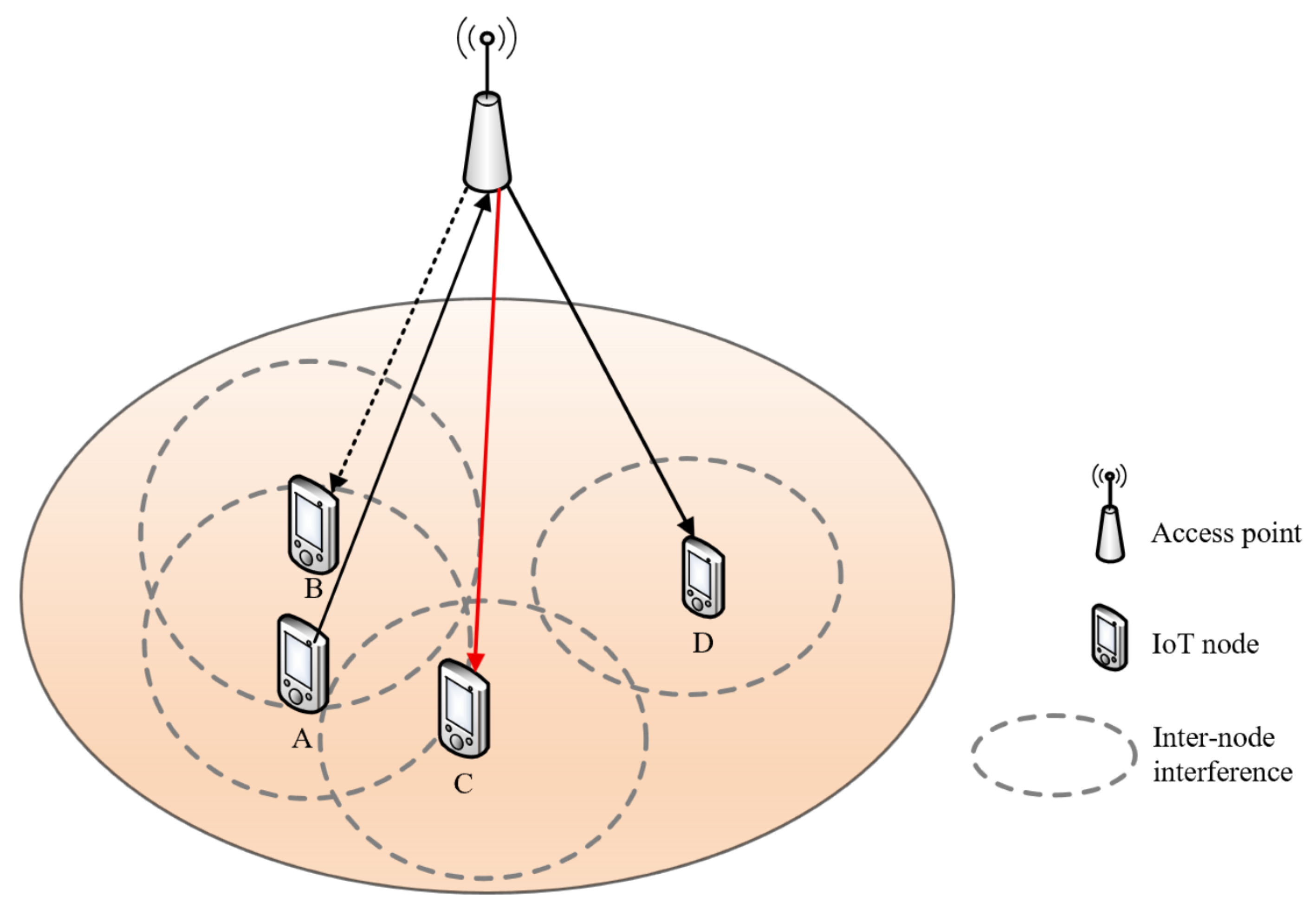
Figure 1. A typical scenario motivating this study. In this scenario, assume an A→AP uplink is established, interference levels are ordered I A B > I A C > I A D (a dashed circle indicates the interference range: when a node is transmitting or receiving, it interferes with all other nodes within this circle), and demand levels are D C > D D > D B . Under a purely interference-aware MAC selection mechanism, the AP selects the AP→D link (solid black line AP→D) to minimize signal disruption. In contrast, our proposed protocol jointly considers both interference and service requirements, leading to the selection of the AP→C link (solid red line) to satisfy the higher QoS demand. The dashed line (AP→B) indicates a potential downlink.
Electronics 14 03901 g001
Figure 2. Operational flow comparison: (a) IDA-FDMAC protocol versus (b) conventional CSMA/CA with RTS/CTS.
Electronics 14 03901 g002
Figure 3. Illustrative example detailing the full transmission sequence of the IDA-FDMAC protocol.
Electronics 14 03901 g003
Figure 4. Architectural layout of the custom CTS-FD frame.
Electronics 14 03901 g004
Figure 5. Illustration of priority-based subcarrier allocation when a UD node initiates the uplink transmission.
Electronics 14 03901 g005
Figure 6. Simulated network layout showing the spatial distribution of nodes and the AP.
Electronics 14 03901 g006
Figure 7. Performance validation of IDA-FDMAC under varying CW from 100 to 500 and priority settings ((ac) as (10,10,10), (50,50,50), and (10,30,50)). Subfigures show (a) average uplink/downlink throughput for a UD node, (b) average uplink/downlink throughput for a DD node, and (c) overall system throughput.
Electronics 14 03901 g007
Figure 8. Comparative performance analysis of IDA-FDMAC, the protocol from [9], and CSMA/CA with CW from 100 to 500 and priority values (8, 12, 16). Subfigures depict (a) uplink and downlink throughput for a UD node, (b) uplink and downlink throughput for a DD node, and (c) total system throughput.
Electronics 14 03901 g008
Figure 9. System throughput under varying load factors for different priority configurations.
Electronics 14 03901 g009
Figure 10. Per-node throughput comparison under varying load factors, demonstrating QoS differentiation.
Electronics 14 03901 g010
Table 1. The TX type value of each TDC transmission type.
CasesTX Type
Case 1 (UD→AP)00
Case 2 (DD→AP)01
Case 3 (AP→UD)10
Case 4 (AP→DD)11
Table 2. Parameter setting in simulation.
ParameterValue
DIFS28 μ s
SIFS10 μ s
Slot time9 μ s
RTS/RTS-FD38/38 bytes
CTS/CTS-FD44/52 bytes
ACK38 bytes
T R 1 8 μ s
T R 2 / T R 3 2 μ s
Payload1500 bytes
R basic 6 Mbps
R data 54 Mbps
T DATA 222 μ s
Disclaimer/Publisher’s Note: The statements, opinions and data contained in all publications are solely those of the individual author(s) and contributor(s) and not of MDPI and/or the editor(s). MDPI and/or the editor(s) disclaim responsibility for any injury to people or property resulting from any ideas, methods, instructions or products referred to in the content.