Article

Oscillation Propagation Analysis of Grid-Connected Converter System with New eVSG Control Patterns

State Grid Anhui Electric Power Co., Ltd., Electric Power Research Institute, Hefei 230601, China
*
Author to whom correspondence should be addressed.
Electronics 2025, 14(19), 3850; https://doi.org/10.3390/electronics14193850
Submission received: 12 August 2025 / Revised: 9 September 2025 / Accepted: 18 September 2025 / Published: 28 September 2025

Abstract

The virtual synchronous generator (VSG) technique plays a crucial role in power systems with high penetration of power electronics, as it can provide virtual inertia and damping performance by emulating the swing characteristics of a synchronous generator (SG). However, the VSG faces challenges due to its inherent limitations, such as vulnerability to disturbances and instability in strong grid conditions. To address these issues, this article proposes an exchanged VSG (eVSG) control strategy. In this approach, the phase information (θ) is derived from reactive power (Q), while the voltage information (E) is derived from active power (P). Furthermore, a Magnitude-Phase Motion Equation (MPME) is introduced to analyze the eVSG system from a physical perspective. Additionally, this article is the first to illustrate the oscillation propagation effect between P and frequency (f) in both VSG and eVSG systems. Finally, the advantages of the eVSG strategy are comprehensively demonstrated through three aspects: (1) comparing the motion trajectory of f using the MPME model, (2) evaluating the oscillation propagation effect between VSG and eVSG systems, and (3) conducting simulations and experiments.

1. Introduction

The integration of renewable energy sources into the grid necessitates the use of power electronic devices. As the scale of renewable energy integration expands, power systems are increasingly characterized by low inertia and weak damping due to the parallel connection of a large number of power electronic devices. This poses significant risks to the safety and stability of power systems. To address this pressing issue, virtual synchronous generator (VSG) control technology has emerged. A VSG simulates the swing characteristics of an SG to control grid-tied inverters, thereby providing inertia and damping support to the power system. This greatly improves the inertia and damping levels of power systems with high penetration of power electronics, making it a hot research topic in recent years.
Recent research on VSGs has primarily focused on the following aspects: First, the establishment of equivalent models for VSG systems [1,2,3,4,5,6,7,8,9,10,11,12,13], including state space models (SSMs) [1,2,3,4], impedance/admittance models (IAMs) [5,6,7,8], magnitude-phase feedback analysis models (MPFAMs) [9,10], open-loop system models (OLSMs) [9,10], and MPMEs models [11,12,13]. Among these, the eigenvalue analysis method is effective in identifying the system’s dominant oscillation modes and damping ratio and can analyze the system’s transient response under step disturbances. However, it cannot identify the physical essence of system instability and is not suitable for large-scale high-order power systems due to the increased computational burden.
In contrast, the impedance/admittance analysis method is another intuitive approach for assessing the stability of power electronic-based power systems. It can reveal the system’s passivity and stability mechanisms from the perspective of network port impedance characteristics. However, it overlooks the internal connections and dynamic interactions between state variables and does not intuitively reveal the physical essence of the system.
MPFAMs are often used in conjunction with OLSMs, and the combination of these two models can effectively determine the oscillation transfer effects between system variables but cannot analyze the system’s terminal characteristics.
The MPME model can analyze the frequency motion process and system stability from a more intuitive physical perspective, but it also cannot be used to analyze the system’s terminal characteristics.
The second research focus is the analysis of low-frequency oscillation (LFO) mechanisms in VSG systems [6,14,15,16,17,18,19,20]. The causes of LFO in VSG systems may include improper design of converter control loops, system disturbances, dynamic interactions between VSG and other devices, and positive feedback effects between state variables in the system. For example, Ref. [14] found that the Nyquist criterion might fail due to impedance interactions between the load-side virtual synchronous machine (LVSM) and the VSG, and increasing the virtual impedance of the LVSM can enhance the stability of VSG-VSM microgrid systems. Ref. [15] demonstrated that VSGs exhibit fast primary frequency regulation characteristics while providing positive damping to low-frequency oscillation modes, and reducing the virtual impedance can enhance the damping performance of the VSG system. Ref. [16] revealed that decreasing the moment of inertia can reduce the oscillation amplitude of frequency in the VSG system.
Additionally, LFO can be triggered by oscillation propagation (OP). Ref. [17] proposed a framework to analyze the OP effect between f and E. This method first establishes the OP framework (OPF) between f and E and identifies the critical frequency point (CFP) through the OLSM. It then evaluates the OP effect based on the amplitude of the OPF at the CFP. However, this method is inconvenient for analyzing the OP effect between P and f because the self-stability loops of P and f are identical. Ref. [18] established the OPF using the iterative function of the system. While this method has clear physical significance, there may be multiple peaks in the amplitude-frequency characteristics of the system’s iterative function, making it difficult to identify the CFP. Ref. [9] analyzed the OP effect using an induced-stability framework, which can determine whether oscillations in a state variable ‘x’ are caused by the loss of self-stability in x. However, this method lacks physical significance.
The third research focus is the design of enhanced control strategies [21,22,23,24,25,26,27]. Adding a feedforward control channel can significantly improve the transient performance of the system, reduce overshoot, and shorten the adjustment time. However, it imposes additional rated values on the control loop, causing the actual values to deviate from the preset values and compromising steady-state performance to some extent [11,21,22]. Other enhancements include an adaptive VSG (AVSG) [23,24], mode-switching VSG (MSVSG) [25], and VSG-based enhanced control structures (VSGECS) [26,27]. AVSGs can suppress LFO by automatically regulating control parameters during transient processes. However, AVSGs are only a transient process management method and cannot prevent LFO by improving the control structure. MSVSGs exhibit excellent synchronization stability, but its implementation is complex and requires highly reliable communication. VSGECS modify the fundamental logic of VSGs, designing control channels not based on swing characteristics of SGs. For example, Ref. [26] proposed a coordinated VSG (CVSG) strategy, which generates the θ of a VSG using the DC-side capacitor voltage rather than P. Compared to traditional VSGs, CVSGs enable flexible photovoltaic power injections and reduces the operational stress on batteries on the DC side. Ref. [27] introduced a rotated VSG (RVSG) strategy, which is based on the principle of power sharing. The RVSG strategy establishes a new reference framework for P, Q, E, and f, generating both E and θ using P and Q. RVSGs can reduce steady-state errors in microgrids with complex line impedances. These studies demonstrate that VSGECS can achieve better performance while providing inertia and damping to grid-tied converter systems, with less emphasis on emulating the swing characteristics of SGs.
Inspired by VSGECS, this article proposes an exchanged VSG (eVSG) strategy, which generates θ from Q and E from P. A Magnitude-Phase Motion Equation (MPME) model is developed to compare the performance of VSGs and eVSGs from a physical perspective. Additionally, to address the lack of modeling methods for analyzing the P-f OP effect in VSG systems, this article proposes a framework combined with an analytical method to evaluate the OP effect between P and f in both VSG and eVSG systems. The contributions of this article are summarized as follows:
  • A novel control strategy named eVSG is proposed. Compared to VSGs, eVSGs exhibit superior performance in both weak and strong grids, as well as in grids with low and high inertia levels.
  • An MPME model for the eVSG system is proposed to analyze the motion of frequency and assess the synchronizing stability of the eVSG system from a physical perspective.
  • A novel modeling method is introduced to evaluate the OP effect between P and f from a physical perspective for both VSG and eVSG systems. This method addresses the limitations of conventional approaches, which cannot effectively analyze the P-f OP effect in VSG systems.
  • The effectiveness of the proposed eVSG strategy and the modeling method is thoroughly validated through simulations and experiments.

2. Modeling of Proposed Grid-Forming Pattern

2.1. Operation Principle of Proposed Grid-Forming Pattern

Figure 1 illustrates the operation of a grid-tied converter in both the conventional grid-forming mode and the proposed grid-forming mode, referred to as ‘eVSG’.
Departing from the conventional concept that VSG control strategies must adhere to the swing characteristics of synchronous generators—where the θ is derived from P and the E is derived from Q—the proposed eVSG strategy innovatively uses Q to form θ and P to form E. Specifically, the ‘Q-θ’ control channel incorporates virtual inertia and damping control to provide inertia and damping performance to the system, while the ‘P-E’ control channel employs proportional-integral (PI) control to ensure controllable active power flow. The control logic is described by
Q r f Q e J p ω g s 2 + D p ω g s + ω g s = θ ( K p + K i / s ) ( P r f P e ) + E r e f = E
By linearizing Equation (1) around the equilibrium point, the small-signal equation is given as
δ Q e J p ω g s 2 + D p ω g s = δ θ δ P e ( K p + K i / s ) = δ E
For comparison, the small-signal equation of the conventional VSG control strategy is given by
δ P e J p ω g s 2 + D p ω g s = δ θ δ Q e J q s + D q = δ E
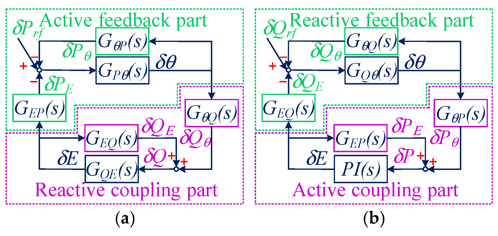
Assuming that the equivalent capacitance effect of the transmission line to the ground can be neglected, the circuit equations in Figure 1 are derived from Kirchhoff’s law as
E e j θ U g e j θ g = [ R f + R t r + R g + s ( L f + L t r + L g ) ] I e j φ
Further assuming that the rotating frequency of the synchronous frame matches the ωg, defining R = Rf + Rtr + Rg, L = Lf + Ltr + Lg, Park’s transformation is applied to Equation (3), the ‘d-q’ decoupling equation is given by
E d U g = ( R + s L ) I d X I q E q = X I d + ( R + s L ) I q
It is noted that Ed = Ecosθ, Eq = Esinθ, X = ωgL. Based on the instantaneous power theory, the P and Q output by the converter can be expressed as
P = 1.5 L P F ( E d I d + E q I q ) Q = 1.5 L P F ( E q I d E d I q )
A low-pass filter (LPF), selected as 314/(s + 314), is used to filter the signals. Combining Equations (4) and (5), the small-signal equations for P, Q, θ, and E are derived as
δ P δ Q = G θ P ( s ) G E P ( s ) G θ Q ( s ) G E Q ( s ) δ θ δ E
where GθP(s), GEP(s), GθQ(s), GEQ(s) are given in Appendix A.
Based on Equations (3) and (7), the multi-input multi-output (MIMO) model of the VSG system is depicted in Figure 2.
Similarly, using Equations (2) and (7), the MIMO model of the eVSG system is illustrated in Figure 3.
By rearranging Figure 2 and Figure 3, the single-input single-output (SISO) models of the VSG and eVSG systems are presented in Figure 4.
Referring to Figure 4, the open-loop transfer functions of the two systems can be derived as
G o p-V S G ( s ) = G θ P ( s ) G θ Q ( s ) G E P ( s ) / [ J q s + D q + G E Q ( s ) ] J p ω g s 2 + D p ω g G o p-e V S G ( s ) = G θ Q ( s ) P I ( s ) G θ P ( s ) G E Q ( s ) / [ 1 + G E P ( s ) P I ( s ) ] J p ω g s 2 + D p ω g
It is noted that Gop-VSG(s) and Gop-eVSG(s) are established to identify the critical frequency point (CFP).

2.2. Proposed MPME Model for eVSGs

In this section, the Magnitude-Phase Motion Equation (MPME) models of VSGs and eVSGs are proposed to better understand the motion trajectory of angular velocity from the perspective of dynamic torque.
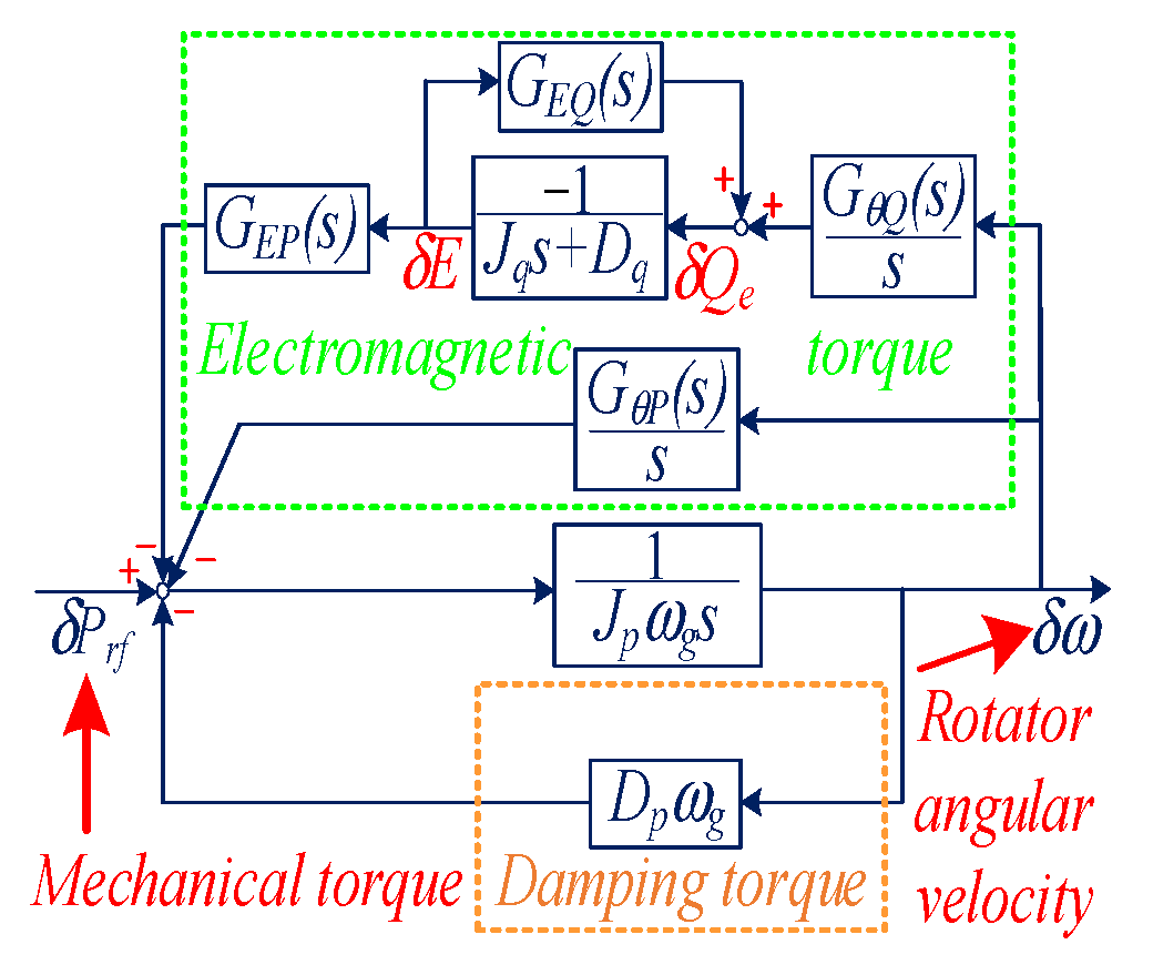
The MPME model comprises three components: the mechanical torque part, the electromagnetic torque part, and the damping torque part. By combining Equations (3) and (7), the MPME model of the VSG can be derived as shown in Figure 5.
The equations for the electromagnetic torque and damping torque of the VSG are given by
G E M T-V S G ( s ) = G θ Q ( s ) G E P ( s ) J q s + D q + G E Q ( s ) + G θ P ( s ) s G D T-V S G ( s ) = D p ω g
It is important to note that in the eVSG configuration, the virtual angular speed (ω) is generated by Q. Therefore, the relationship between virtual torque (T) and virtual angular speed is derived from
δ T = δ Q / δ ω
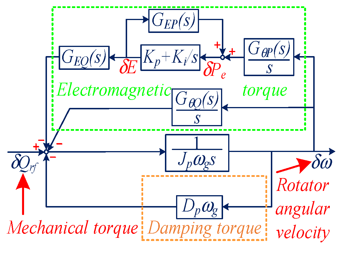
By combining Equations (2), (7) and (10), the MPME model of the eVSG can be derived as illustrated in Figure 6.
The equations for the electromagnetic torque and damping torque of the eVSG are provided in
G E M T-e V S G ( s ) = ( K p + K i ) G θ P ( s ) G E Q ( s ) s + ( K p + K i ) G E P ( s ) + G θ Q ( s ) s G D T-e V S G ( s ) = D p ω g
The electromagnetic torque component is responsible for synchronizing the VSG/eVSG to eliminate steady-state errors and mitigate transient deviations. The damping torque provides damping performance to ensure the system can return to its initial state after a transient process. The stability of the system can be assessed by analyzing the quadrant of the synthetic torque in the δθ-δω coordinate system.

2.3. Case Study Based on the MPME Mode

To illustrate the principle of the MPME model, Cases I–III are conducted. The universal parameters of the VSG and eVSG for Cases I–III are provided in Table 1.
It is noted that the short-circuit ratio (SCR) reflects the strength of the power system grid. The vectors of mechanical torque (MT), electromagnetic torque (EMT), and damping torque (DT) are obtained from the magnitude and phase at the critical frequency point (CFP) in the transfer functions GEMT(s) and GDT(s) of the VSG/eVSG. The synthetic torque (ST) is derived by combining MT and EMT.
The relationship between δθ and δω for both the VSG and eVSG is expressed by
δ ϑ = δ ω / s
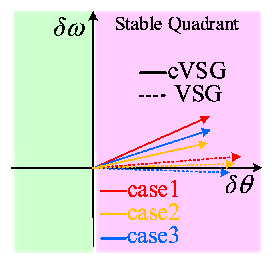
Based on the physical meaning of the magnitude-phase motion, the vector of ST can exist in any of the four quadrants in the δθ-δω coordinate system. However, the system remains stable only when the vector lies in the first quadrant. Figure 7 shows the synthetic torque of the VSG and eVSG for Cases I–III.
As illustrated in Figure 7, under the same operating conditions, the vectors of the VSG are closer to the unstable quadrant, indicating that the VSG tends to lose stability in Cases I–III. In contrast, the eVSG control demonstrates superior performance compared to the VSG control, whether in a strong grid (SCR = 4.326), a medium-strength grid (SCR = 2.6), or a weak grid (SCR = 1.62) when subjected to the same disturbance. The amplitude and phase of each ST for Cases I–III are provided in Table 2.
It is noted that the abscissa represents the amplitude of ST, while the ordinate represents the phase of ST.
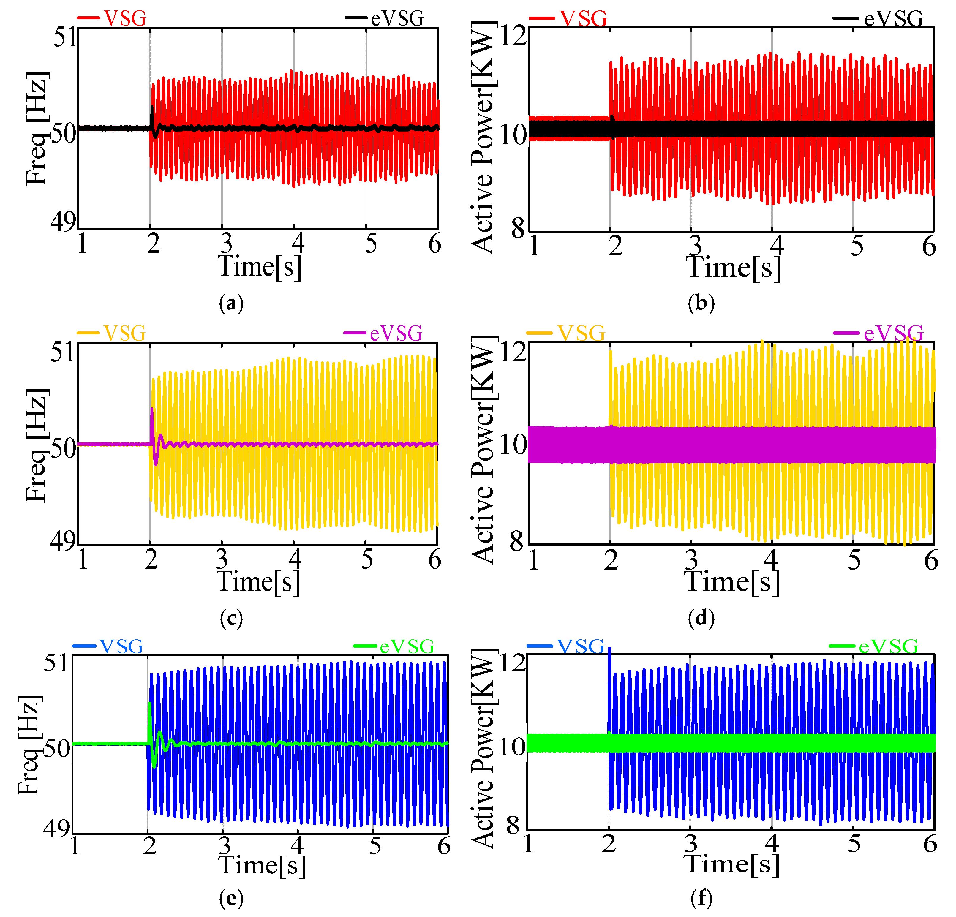
To further validate the performance of the eVSG strategy, simulation results are presented in Figure 8, and the stability margins for Cases I–III, derived from the system’s open-loop transfer function in Equation (8), are provided in Table 3.
In Table 3, the abscissa represents the frequency (ω) of the CFP, and the ordinate represents the phase margin of the selected case. From the above analysis, it can be inferred that the proposed MPME model for the eVSG aligns well with the simulation and analysis results. The model effectively reflects the system’s stability margin and the risk of oscillation from a perspective with clearer physical meaning.

3. Oscillation Propagation Analysis for eVSG Strategy

3.1. Establishment of Modeling for Oscillation Propagation

Figure 9 illustrates the transfer relationships between small-signal variables in the VSG and eVSG systems.
The oscillation propagation judgment framework between δf and δP in the VSG and eVSG systems can be derived from Figure 9, as expressed in
G P f-V S G ( s ) = 1 2 π ( J p ω g s + D p ω g ) G f p-V S G ( s ) = 2 π [ G θ P ( s ) G θ Q ( s ) G E P ( s ) ] J q s 2 + D q s + s G E Q ( s ) G P f-e V S G ( s ) = P I ( s ) G E Q ( s ) 2 π G θ Q ( s ) s + 2 π ( J p ω g s + D p ω g ) G f p-e V S G ( s ) = 2 π G θ P ( s ) s + s P I ( s ) G E P ( s )
Here, Gpf-VSG(s) is designed to evaluate the transfer effect from P to f in the VSG system, while Gfp-VSG(s) is used to assess the transfer effect from f to P in the VSG system. Similarly, Gpf-eVSG(s) and Gfp-eVSG(s) serve the same purposes in the eVSG system.

3.2. Oscillation Propagation Bewteen Frequency and Active Power

The oscillation propagation between frequency and active power in the VSG/eVSG system can be determined by the magnitude of Gpf(s) and Gfp(s) at the critical frequency point (CFP) ωs. From the physical meaning of the transfer function, if 20lg[Gpf(jωs)] exceeds 0, it indicates a positive transfer effect from P to f, causing f to resonate due to this positive effect. Similarly, if 20lg[Gfp(jωs)] exceeds 0, P tends to resonate due to the positive transfer effect from f.
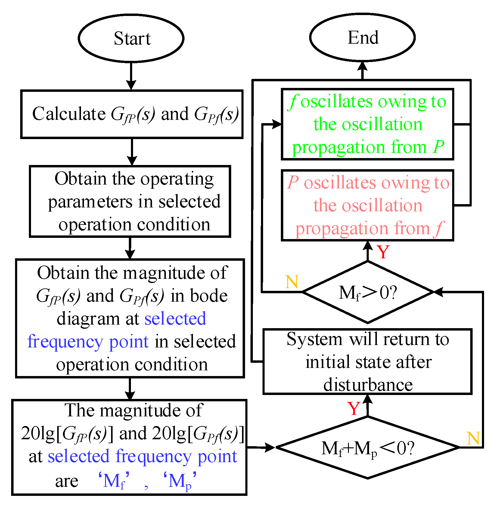
Figure 10 outlines the procedure for judging oscillation propagation between frequency and active power in the VSG and eVSG systems. The detailed steps are as follows:
Step 1: Establish the framework of Gpf-VSG(s), Gfp-VSG(s), Gpf-eVSG(s), Gfp-eVSG(s).
Step 2: Obtain the operating parameters and critical frequency (ωs) for the selected system’s operating condition.
Step 3: Plot the bode diagram of Gpf(s) and Gfp(s) and extract their magnitude information at the selected frequency point, denoted as ‘Mp’ and ‘Mf’.
Step 4: Determine whether Mp + Mf < 0. If true, the system has a positive stability margin and will return to its initial state after a disturbance. If not, proceed to Step 5.
Step 5.1: Check if both Mf and Mp are greater than 0.
Step 5.2: If Mf > 0 while Mp < 0, it indicates a positive effect from f to P but a negative effect from P to f. Consequently, P will oscillate significantly, while f will also resonate, albeit to a lesser degree due to the negative effect from P. In this case, the direction of oscillation propagation is from f to P. The opposite scenario applies if Mp > 0 and Mf < 0.
Step 5.3: If both Mf and Mp are greater than 0, it signifies severe oscillation in both P and f, leading to eventual divergence.
It is important to note that the larger the magnitudes of Mf and Mp, the greater the degree of oscillation.

3.3. Case Studies

To further verify the proposed oscillation propagation framework and the analytical method for VSG and eVSG systems, a case study is carried out. The universal parameters of VSG and eVSG systema in Case IV~VI are given in Table 4.
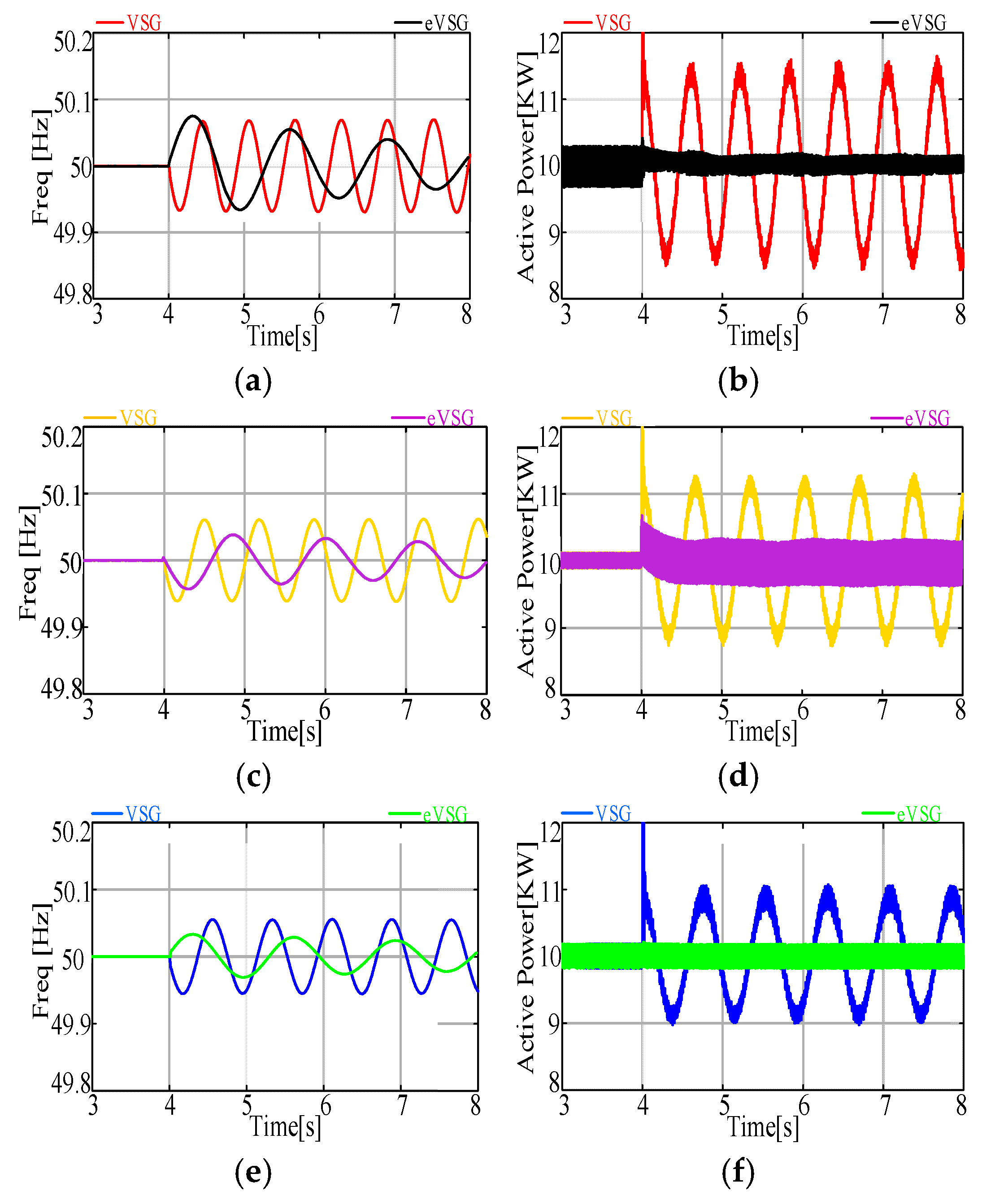
Theoretical and simulation verification are shown in Figure 11 and Figure 12.
As shown in Figure 11a,c,e indicated that the system with VSG control in Cases IV–VI suffered from resonance oscillation, and the direction of oscillation transfer was from f to P, which indicated that the P is oscillation with a large degree while f is oscillation with a quite small degree due to the negative effect from P. Analytical results in Figure 11a,c,e are matched well with the simulation results of the VSG system in Figure 12.
As shown in Figure 11b,d,f, although the Mf of the eVSG system is above 0, the sum of Mf and Mp is less than 0, it is the reason that f has a positive effect on P but P can return to initial state after a disturbance. It also can be directly judged from comparison of the magnitude of Gpf(s) and Gfp(s) at the CFP in the VSG and eVSG systems that both 20lg[Gpf(jωs)] and 20lg[Gfp(jωs)] in the eVSG system obviously has a smaller value than in the VSG system, which illustrated that whether P or f in the eVSG system have a smaller oscillation degree when suffering the same disturbance under the same operating conditions compared with VSG system. It also means that grid-tied converter systems with an eVSG pattern has better performance on robustness than the VSG pattern. The analysis results in Figure 11b,d,f matched well with the simulation results of the eVSG system in Figure 12.
It can be derived from above analysis that compared with the VSG control pattern, the proposed eVSG control pattern has an obvious advantage on system performance in a wide range of SCR (from 1.62 to 4.326) and a wide range of inertia levels (from 0.0125 to 1), which verified the effectiveness of the eVSG strategy.

4. Experimental Verification

To fully embody the advantage of the eVSG control pattern and further verify the proposed P-f oscillation propagation framework for the VSG and eVSG systems, experiments which built upon the topology and control structure shown in Figure 1 are carried out.
It is noted that the parameters of the experiments established are completely the same as the corresponding simulations.
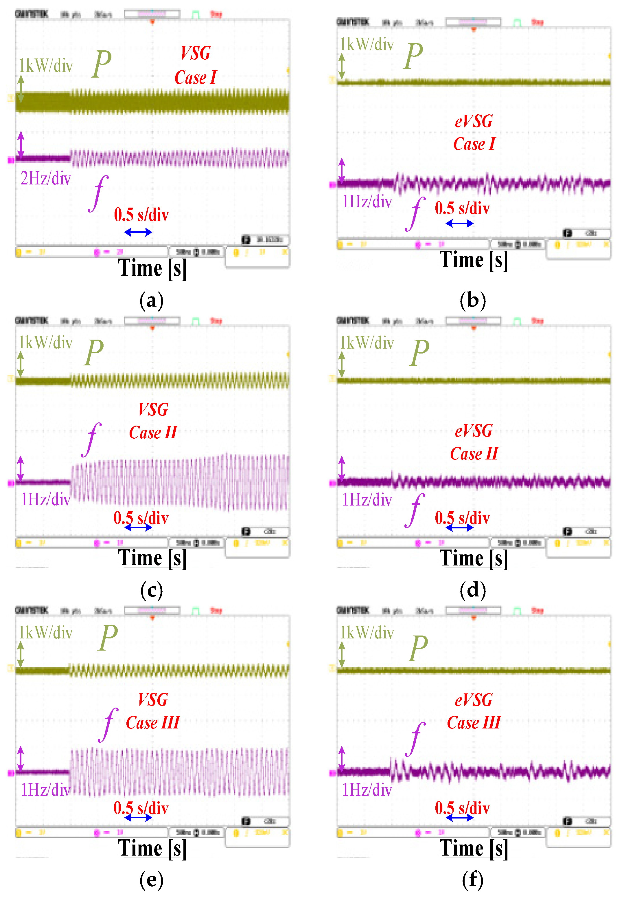
As can be seen in Figure 13, when operating in the same conditions, the eVSG control pattern has more significant grid robustness in a wide range of power grid strength (SCR from 1.62 to 4.326), which verified that the system with the eVSG pattern has better performance when suffering the same disturbance, i.e., the system with the VSG strategy suffers a sustained resonance oscillation while the resonance in the eVSG system was already attenuated. The conclusion drew by experiment results of Cases I–III are consistent with the conclusion of the simulation results, which verified the superiority of the eVSG strategy and the proposed MPME model for the eVSG.
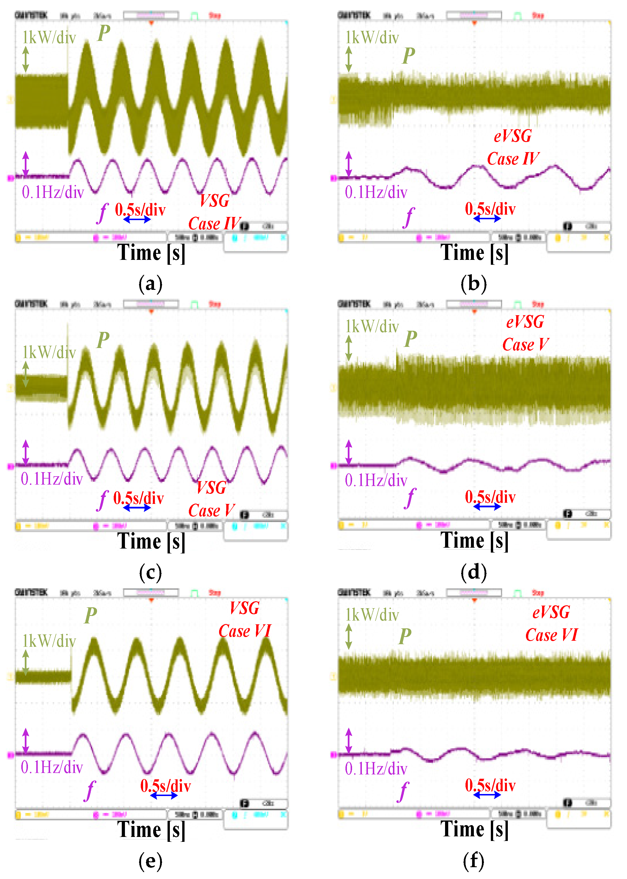
As shown in Figure 14, when suffering the same disturbance, the resonance in the system with the eVSG strategy is going to converge, while the system with the VSG strategy suffers a constant-amplitude oscillation. It indicated that, when operating in the high inertia level grid (Jp = 1), the eVSG control strategy has better transient state and steady state performance compared with the VSG control strategy under the same operating conditions in a wide range of power grid strength. The oscillation degree and oscillation frequency in Figure 14 overlapped with the conclusion of the theoretical analysis in Figure 11, which verified the proposed oscillation propagation framework and oscillation propagation analytical method between ‘P’ and ‘f’ for the eVSG system.

5. Conclusions

This article proposed a new eVSG pattern which adopted the reactive power to form the phase of the converter and the active power to form the voltage of the converter. The advantage of the eVSG was verified by the proposed MPME model compared with the conventional VSG in the MPME model with the same operating conditions and the same disturbance. The oscillation propagation modeling and analytic method between P and f for the VSG and eVSG systems was proposed, and the results of oscillation propagation analysis also verified that the eVSG strategy has a better performance than the VSG. The main conclusions of this article are as follows:
By comparison of the VSG and eVSG systems from a physical perspective of magnitude-phase motion, it can be concluded that whether in a strong grid or weak grid (SCR from 1.62 to 4.326), the eVSG strategy has significantly better performance on robustness than the VSG strategy.
  • By comparison of the VSG and eVSG systems from a perspective of oscillation and its transfer, it can be concluded that, in a wide range of grid inertia levels (Jp from 0.0125 to 1) and grid-tied systems, the eVSG strategy has significantly better performance on robustness than the VSG strategy when suffering same disturbance.
  • Oscillation will occur when system has a negative stability margin, and the direction of oscillation propagation between P and f can be judged by the proposed framework and analytical method, also the degree of oscillation can be judged by the proposed framework.
  • The simulations and experiment results also illustrated that whether in a strong grid, weak grid, high inertia level grid or low inertia level grid, grid-tied systems with the eVSG strategy had better performance on robustness compared with the conventional VSG strategy.

Author Contributions

Conceptualization, B.X.; Methodology, H.Z.; Validation, H.Z.; Formal analysis, Y.X.; Investigation, H.Z. and J.L.; Resources, Y.X.; Data curation, J.L.; Writing—original draft, B.X.; Supervision, W.M. All authors have read and agreed to the published version of the manuscript.

Funding

This work was supported by the ‘Research on DC distribution systems, Operation Control, and Positioning Key Technologies and Applications’ of the State Grid Anhui Electric Power Science and Technology Project (B3120524003J).

Data Availability Statement

The data presented in this study are available in this article.

Conflicts of Interest

All author were employed by the company State Grid Anhui Electric Power Co., Ltd. The authors declare that the research was conducted in the absence of any commercial or financial relationships that could be construed as a potential conflict of interest.

Appendix A

G θ P ( s ) = E U g ( R + s L ) s i n ( θ ) + E U g ω g L c o s ( θ ) ( R + s L ) 2 + ( ω g L ) 2 G E P ( s ) = [ 2 E U g c o s ( θ ) ] ( R + s L ) + U g ω g L s i n ( θ ) ( R + s L ) 2 + ( ω g L ) 2 G θ Q ( s ) = E U g ( R + s L ) c o s ( θ ) + E U g ω g L s i n ( θ ) ( R + s L ) 2 + ( ω g L ) 2 G E Q ( s ) = U g ( R + s L ) s i n ( θ ) + ω g L [ 2 E U g c o s ( θ ) ] ( R + s L ) 2 + ( ω g L ) 2

References

  1. Du, W.; Fu, Q.; Wang, H.F. Power system small-signal angular stability affected by virtual synchronous generators. IEEE Trans. Power Syst. 2019, 34, 3209–3219. [Google Scholar] [CrossRef]
  2. Pourmohammad, M.; Toulabi, M.; Ranjbar, A.M. Application of state feedback controller to ensure robust d-stable operation of virtual synchronous generators. IEEE Trans. Energy Convers. 2021, 36, 602–610. [Google Scholar] [CrossRef]
  3. Roldán-Pérez, J.; Rodríguez-Cabero, A.; Prodanovic, M. Design and analysis of virtual synchronous machines in inductive and resistive weak grids. IEEE Trans. Energy Convers. 2019, 34, 1818–1828. [Google Scholar] [CrossRef]
  4. Mauricio, J.M.; Leon, A.E. Improving small-signal stability of power systems with significant converter-interfaced generation. IEEE Trans. Power Syst. 2020, 35, 2904–2914. [Google Scholar] [CrossRef]
  5. Wang, H.; Xie, Z.; Chen, Y.; Wu, W.; Wang, Z.; Lin, G.; Guo, J. Admittance-Based Stability Analysis of Current-Controlled VSG Considering the Frequency Coupling Characteristics. IEEE J. Emerg. Sel. Top. Power Electron. 2023, 11, 1191–1202. [Google Scholar] [CrossRef]
  6. Fu, S.; Sun, Y.; Lin, J.; Chen, S.; Su, M. P/Q-ω/V Admittance Modeling and Oscillation Analysis for Multi-VSG Grid-Connected System. IEEE Trans. Power Syst. 2023, 38, 5849–5859. [Google Scholar] [CrossRef]
  7. Wu, W.; Chen, Y.; Zhou, L.; Luo, A.; Zhou, X.; He, Z.; Yang, L.; Xie, Z.; Liu, J.; Zhang, M. Sequence Impedance Modeling and Stability Comparative Analysis of Voltage-Controlled VSGs and Current-Controlled VSGs. IEEE Trans. Ind. Electron. 2019, 66, 6460–6472. [Google Scholar] [CrossRef]
  8. Zhou, L.; Shuai, Z.; Chen, Y.; Wu, W.; Zhou, X.; Yan, K.; Luo, A. Impedance-Based Harmonic Current Suppression Method for VSG Connected to Distorted Grid. IEEE Trans. Ind. Electron. 2020, 67, 5490–5502. [Google Scholar] [CrossRef]
  9. Li, C.; Yang, Y.; Blaabjerg, F. Mechanism Analysis for Oscillation Transferring in Grid-Forming Virtual Synchronous Generator Connected to Power Network. IEEE Trans. Ind. Electron. 2025, 72, 8715–8720. [Google Scholar] [CrossRef]
  10. Li, C.; Li, Y.; Du, Y.; Gao, X.; Yang, Y.; Cao, Y.; Blaabjerg, F. Self-Stability and Induced-Stability Analysis for Frequency and Voltage in Grid-Forming VSG System With Generic Magnitude-Phase Model. IEEE Trans. Ind. Inform. 2024, 20, 12328–12338. [Google Scholar] [CrossRef]
  11. Li, C.; Yang, Y.; Mijatovic, N.; Dragicevic, T. Frequency Stability Assessment of Grid-Forming VSG in Framework of MPME With Feedforward Decoupling Control Strategy. IEEE Trans. Ind. Electron. 2022, 69, 6903–6913. [Google Scholar] [CrossRef]
  12. Li, C.; Yang, Y.; Li, Y.; Cao, Y.; Murashov, I.; Xu, J.; Aleshina, A.; Blaabjerg, F. Generalized stabilizer-oriented design for GFVSG integrated into weak-stiffness power networks. IEEE Trans. Power Syst. 2022, 37, 4958–4961. [Google Scholar] [CrossRef]
  13. Li, C.; Cao, Y.; Yang, Y.; Xu, J.; Wu, M.; Zhang, W.; Dragičević, T. New framework of RoCoF-FD for wideband stability evaluation in renewable energy generators with virtual impedance control. IEEE Trans. Smart Grid 2022, 13, 3570–3581. [Google Scholar] [CrossRef]
  14. Guo, J.; Chen, Y.; Liao, S.; Wu, W.; Zhou, L.; Xie, Z.; Wang, X. Analysis and Mitigation of Low-Frequency Interactions Between the Source and Load Virtual Synchronous Machine in an Islanded Microgrid. IEEE Trans. Ind. Electron. 2022, 69, 3732–3742. [Google Scholar] [CrossRef]
  15. Liu, H.; Sun, D.; Song, P.; Cheng, X.; Zhao, F.; Tian, Y. Influence of Virtual Synchronous Generators on Low Frequency Oscillations. CSEE J. Power Energy Syst. 2022, 8, 1029–1038. [Google Scholar] [CrossRef]
  16. Qin, B.; Xu, Y.; Yuan, C.; Jia, J. A Unified Method of Frequency Oscillation Characteristic Analysis for Multi-VSG Grid-Connected System. IEEE Trans. Power Deliv. 2022, 37, 279–289. [Google Scholar] [CrossRef]
  17. Li, C.; Yang, Y.; Li, Y.; Liu, Y.; Blaabjerg, F. Modeling for Oscillation Propagation With Frequency-Voltage Coupling Effect in Grid-Connected Virtual Synchronous Generator. IEEE Trans. Power Electron. 2025, 40, 82–86. [Google Scholar] [CrossRef]
  18. Cheng, H.; Li, C.; Ghias, A.M.M.; Blaabjerg, F. Dynamic Coupling Mechanism Analysis Between Voltage and Frequency in Virtual Synchronous Generator System. IEEE Trans. Power Syst. 2024, 39, 2365–2368. [Google Scholar] [CrossRef]
  19. Ma, Y.; Xu, J.; Gao, C.; Li, G.; Wang, K. Low-frequency Oscillations and Resonance Analysis of VSG-controlled PMSG-based Wind Generation Systems. J. Mod. Power Syst. Clean 2025, 13, 115–127. [Google Scholar] [CrossRef]
  20. Wen, T.; Zhu, D.; Zou, X.; Jiang, B.; Peng, L.; Kang, Y. Power Coupling Mechanism Analysis and Improved Decoupling Control for Virtual Synchronous Generator. IEEE Trans. Power Electron. 2021, 36, 3028–3041. [Google Scholar] [CrossRef]
  21. Yu, Y.; Chaudhary, S.K.; Tinajero, G.D.; Xu, L.; Bakar, N.N.A.; Vasquez, J.C.; Guerrero, J.M. A Reference-Feedforward-Based Damping Method for Virtual Synchronous Generator Control. IEEE Trans. Power Electron. 2022, 37, 7566–7571. [Google Scholar] [CrossRef]
  22. Li, M.; Yu, P.; Hu, W.; Wang, Y.; Shu, S.; Zhang, Z.; Blaabjerg, F. Phase Feedforward Damping Control Method for Virtual Synchronous Generators. IEEE Trans. Power Electron. 2022, 37, 9790–9806. [Google Scholar] [CrossRef]
  23. Alipoor, J.; Miura, Y.; Ise, T. Power System Stabilization Using Virtual Synchronous Generator With Alternating Moment of Inertia. IEEE J. Emerg. Sel. Top. Power Electron. 2015, 3, 451–458. [Google Scholar] [CrossRef]
  24. Wang, Z.; Chen, Y.; Li, X.; Liao, S.; Xu, Y.; Wu, W.; Wang, H.; Cao, S. Impedance-Based Adaptively Reshaping Method for Enhancing Nonlinear Load Sharing and Voltage Quality in Islanded Microgrids With Virtual Synchronous Generator. IEEE Trans. Smart Grid 2022, 13, 2568–2578. [Google Scholar] [CrossRef]
  25. Wu, H.; Wang, X. A Mode-Adaptive Power-Angle Control Method for Transient Stability Enhancement of Virtual Synchronous Generators. IEEE J. Emerg. Sel. Top. Power Electron. 2020, 8, 1034–1047. [Google Scholar] [CrossRef]
  26. Liu, Y.; Wang, Y.; Wang, M.; Xu, Z.; Peng, Y.; Li, M. Coordinated VSG Control of Photovoltaic/Battery System for Maximum Power Output and Grid Supporting. IEEE J. Emerg. Sel. Top. Circuits Syst. 2022, 12, 301–309. [Google Scholar] [CrossRef]
  27. Campo-Ossa, D.D.; Sanabria-Torres, E.A.; Vasquez-Plaza, J.D.; Rodriguez-Martinez, O.F.; Garzon-Rivera, O.D.; Andrade, F. Novel Rotated Virtual Synchronous Generator Control for Power-Sharing in Microgrids with Complex Line Impedance. Electronics 2023, 12, 2156. [Google Scholar] [CrossRef]
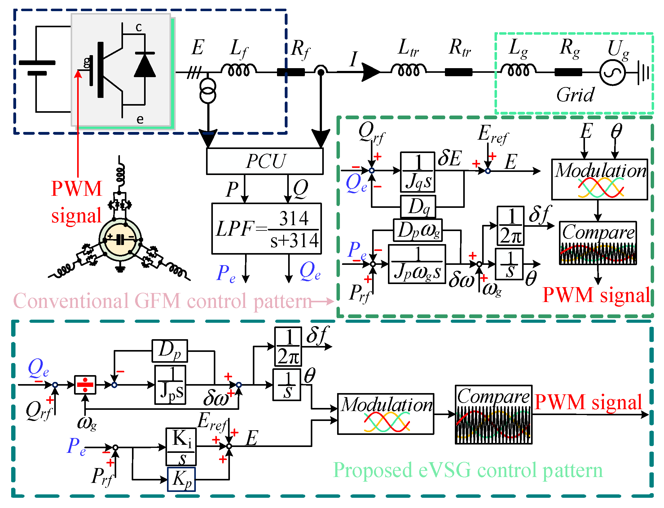
Figure 1. Topology and control logic of the VSG and eVSG.
Electronics 14 03850 g001
Figure 2. MIMO model of the VSG.
Electronics 14 03850 g002
Figure 3. MIMO model of the eVSG.
Electronics 14 03850 g003
Figure 4. SISO model of the VSG and eVSG. (a) VSG, (b) eVSG.
Electronics 14 03850 g004
Figure 5. MPME model of the VSG.
Electronics 14 03850 g005
Figure 6. MPME model of the eVSG.
Electronics 14 03850 g006
Figure 7. Synthetic vector diagram of the VSG and eVSG.
Electronics 14 03850 g007
Figure 8. Simulation results of Cases I–III. (a,c,e) are the waveform of frequency, in turns are Cases I–III. (b,d,f) are the waveform of ‘P’, in turns are Cases I–III.
Electronics 14 03850 g008
Figure 9. Small signal transfer model, (a) VSG, (b) eVSG.
Electronics 14 03850 g009
Figure 10. Flowchart for judging the oscillation propagation between P and f.
Electronics 14 03850 g010
Figure 11. Amplitude-frequency characteristics of Gfp(s) and Gpf(s). (a,c,e) Are the analytical results of the VSG system, in turns are Cases IV–VI. (b,d,f) are the analytical results of the eVSG system, in turns are Cases IV–VI.
Electronics 14 03850 g011
Figure 12. Simulation results of Cases IV–VI, (a,c,e) are the simulation results of frequency, followed by Cases IV–VI. (b,d,f) Are the simulation results of active power, followed by Cases IV–VI.
Electronics 14 03850 g012
Figure 13. Experimental results. (a,c,e) Are the experiment results of Cases I–III of the VSG system. (b,d,f) Are the experiment results of Cases I–III of the eVSG system.
Electronics 14 03850 g013
Figure 14. Experimental results. (a,c,e) Are the experiment results of Cases IV–VI of the VSG system. (b,d,f) Are the experiment results of Cases IV–VI of the eVSG system.
Electronics 14 03850 g014
Table 1. Universal parameters of Cases I–III.
Case ICase IICase III
Rf0.10.10.1
Lf/mH4.44.44.4
Rtr0.80.80.8
Ltr/mH4.64.64.6
SCR4.3262.61.62
Jp0.01250.01250.0125
Dp0.4990.410.317
Jq/Ki0.25/0.10.25/0.10.25/0.1
Dq/Kp520/0.5520/0.5520/0.5
ωg100π100π100π
Eref311.127311.127311.127
Power level10 kW10 kW10 kW
Table 2. Synthetic torque information.
VSGeVSG
Case I(89.2, 360.342)(78.5, 28.521)
Case II(87.6, 360.2826)(78.5, 25.3)
Case III(85.7, 359.9056)(77.6, 18.987)
Table 3. Phase margin of Cases I–III.
VSGeVSG
Case I(85.5, 0.342)(38.8, 35.2)
Case II(78, 0.279)(38.7, 29.7)
Case III(70.2, −0.0952)(39.7, 20.9)
Table 4. Universal parameters of Cases IV–VI.
Case VICase VCase VI
Rf0.10.10.1
Lf/mH4.44.44.4
Rtr0.80.80.8
Ltr/mH4.64.64.6
SCR4.3262.61.62
Jp111
Dp0.4970.4210.323
Jq/Ki0.5/0.10.5/0.10.5/0.1
Dq/Kp987/0.5987/0.5987/0.5
ωg100π100π100π
Eref311.127311.127311.127
Power level10 kW10 kW10 kW
Disclaimer/Publisher’s Note: The statements, opinions and data contained in all publications are solely those of the individual author(s) and contributor(s) and not of MDPI and/or the editor(s). MDPI and/or the editor(s) disclaim responsibility for any injury to people or property resulting from any ideas, methods, instructions or products referred to in the content.