1. Introduction
Single-platform Ka-band interferometric Synthetic Aperture Radar (SAR) systems are a consolidated observation technique for environmental monitoring and security applications. This is especially true with the rise of technologies like Along Track Interferometry (ATI) and Ground Moving Target Indication (GMTI), which are used in Earth observation missions that demand high-resolution imaging over large areas.
Traditionally, SAR systems face challenges in achieving both high resolution and wide coverage simultaneously [
1,
2], which are generally overcome with the use of modern techniques like digital beam forming. Methods such as Multiple Azimuth Phase Centres SAR (MAPS) and Scan on Receive (SCORE) show great potential for meeting these goals. MAPS [
3,
4], for instance, uses multiple antenna sections aligned in the direction of motion, which requires long antenna structures. For practical use in space missions, these large antennas must be foldable [
5,
6,
7] to fit into launch vehicles. In addition to being compact and foldable, the antennas also need to deliver high efficiency and low signal loss. Reflectarray technology [
8,
9] stands out as a strong candidate for such SAR applications, offering the performance and flexibility needed to meet these requirements.
A reflectarray consists of an array of radiating elements, often printed on a planar substrate, that reflects and shapes the incoming wavefront from a primary feed source. These elements are engineered with variable phase-shifting properties, allowing precise control over the reflected wave’s direction. Unlike parabolic reflectors, which rely on a fixed curvature to focus signals, reflectarrays achieve beamforming through element design and phase tuning, enabling compact form factors and easier fabrication.
Reflectarray antennas offer several advantages over conventional antenna technologies. Their inherently planar configuration contributes to reduced volume and mass, making them well-suited for applications with stringent constraints on size. High aperture efficiency can be achieved using flat substrate architectures, which occupy minimal space when folded. Furthermore, the use of printed circuitry on lightweight dielectric substrates enables significant reductions in both mass and manufacturing cost [
7]. Additionally, reflectarrays offer design flexibility, enabling multiband operation [
10,
11,
12], polarization control [
13], and reconfigurability [
14,
15,
16]. By integrating tunable materials or electronic components, modern reflectarrays can dynamically adapt to changing communication requirements, opening avenues for advanced functionalities like beam steering and frequency agility. Due to these advantages, the reflectarray technology is well-suited for SAR applications [
17].
In the ESA-funded project MASKARA, the objective is to design a Ka-band reflectarray enabling the SAR instrument to support both ATI and GMTI. This is achieved by implementing polarization-dependent beamwidths, providing one narrow pencil beam and one moderately broad beam. The targeted system concept is intended to deliver gain values above 45 dBi, an azimuth beamwidth of approximately 0.33°, and an elevation beamwidth of 1.2–2.4°, with a swath width in the range of 10–100 km and a resolution of roughly 0.75 m. This paper presents the complete development process, encompassing the antenna architecture, design methodology, manufacturing approach, and RF testing of the Breadboard Model (BBM). Some preliminary results are presented in [
18].
2. Antenna Architecture
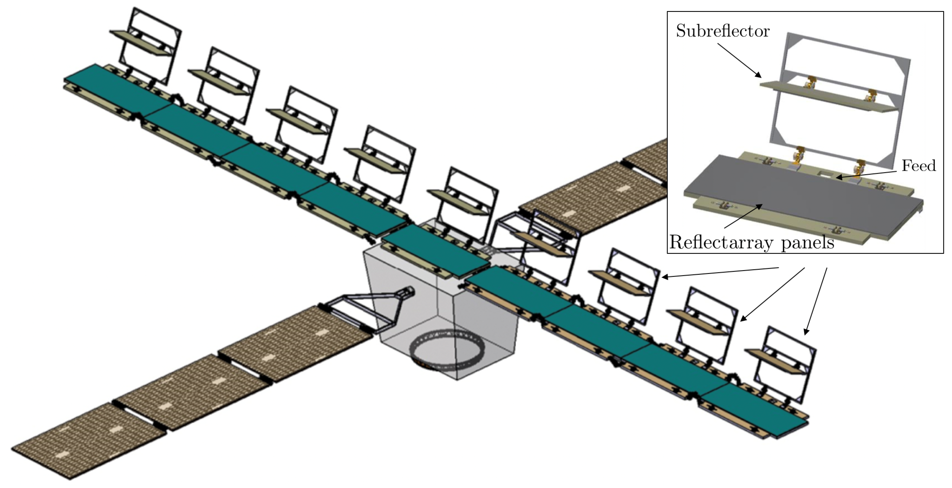
The antenna architecture adopted for this application is illustrated in
Figure 1. It consists of nine reflectarray panels, each with dimensions of 1.5 m × 0.55 m. While single-offset configurations have been previously investigated (e.g., [
19]), the dual-offset configuration selected in this study presents several advantages from both RF and mechanical perspectives.
From an RF standpoint, the dual-offset setup results in reduced transmission losses due to the shorter waveguide lengths between the feeds and reflectarray panels, as the feeds are positioned in or near the plane of the panels. Furthermore, all feeds and subreflectors are located on the same side of the reflectarray, allowing radiation in the specular direction relative to the incoming field. This configuration helps to minimize beam squint effects that may occur when operating away from the center frequency.
Mechanically, the use of subreflectors significantly simplifies deployment, requiring fewer components than more complex alternatives involving additional waveguides, rotary joints, and structural masts. The compact nature of the dual-offset optics also contributes to greater feed stability and reduces the need for structural reinforcements. These characteristics are especially beneficial for stowage and deployment within the constraints of a launch vehicle. As shown in
Figure 2, the full MASKARA system, including the antenna and spacecraft platform, can be efficiently accommodated within the Vega-C launch envelope.
Unlike previous studies such as [
19], which employed idealized array elements, the present work considers realistic and manufacturable elements in the design and analysis of the reflectarray system.
The reflectarray antenna must operate between 35.5–36.0 GHz in two operational modes, a high-resolution mode for one linear polarization, and a low-resolution mode in the orthogonal polarization. For each resolution mode, different gain and pattern specifications apply. The pattern requirements are summarised in
Table 1.
2.1. Subreflector Design
In the initial design phase, two subreflector designs were considered, a large rectangular planar subreflector (configuration 1), and a smaller square curved subreflector (configuration 2). For the first configuration, an elliptical feed pattern is required due to the rectangular shape of the subreflector. However, the subreflector is planar and the configuration provides good RF performance. The second configuration had a smaller subreflector, but it has to be curved in order to reflect the incidence field from the feed to provide a proper illumination over the main reflectarray. Furthermore, a circular feed pattern is needed in configuration 2, making the feed design easier, but this configuration provided degraded performance compared to the first configuration. Furthermore, the curved subreflector complicated the stowage of the reflectarray. Consequently, configuration 1 was selected as seen in
Figure 1.
The subreflector has a dimension of 700 mm × 250 mm and consists of a flat sandwich panel made of high modulus CFRP skins and a lightweight aluminium honeycomb core, bonded to the skins with film adhesive in a single-step co-curing process. The reflective surface of the sandwich panel will be coated with a Kapton VDA metallization in order to minimise reflection losses.
2.2. Feed Design
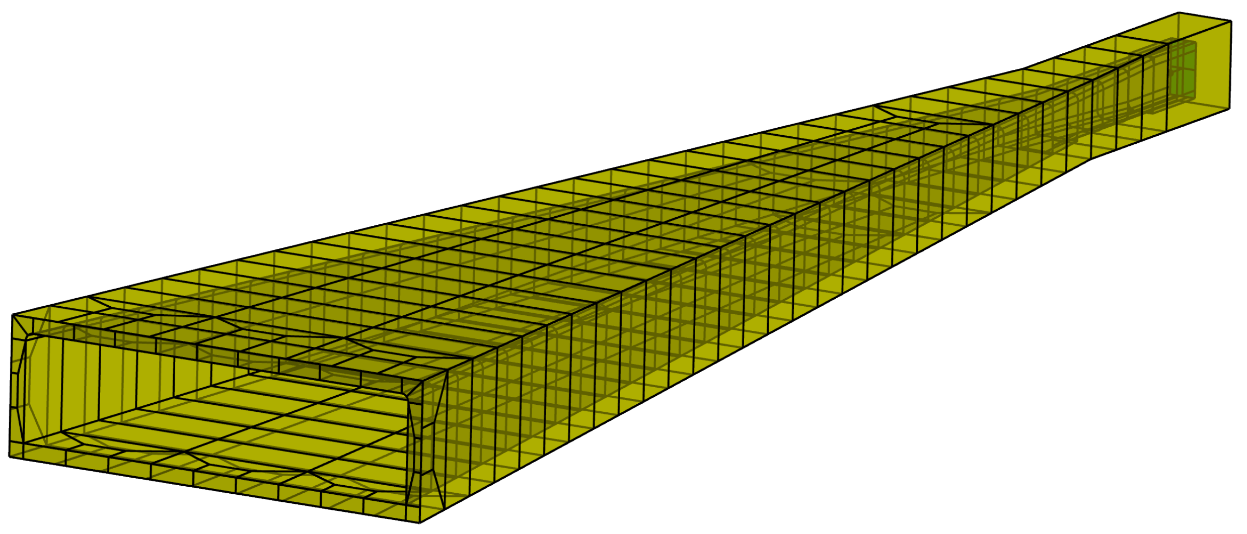
The rectangular shape of the subreflector necessitates an elliptical feed pattern. To this end, the sectoral horn as shown in
Figure 3 has been designed to provide the necessary pattern to illuminate the planar subreflector. The feed has an aperture of 55 mm × 14 mm and a flare length of 200 mm and can be fed by two orthogonal polarizations through WR-28 rectangular waveguide ports to accommodate the need for two different operational modes of the SAR instrument.
The feed was designed and optimized using the software tool ESTEAM [
20], which is based on a full-wave method of moments (MoM) solver—see
Figure 3. The feed was then manufactured and measured, and good agreement between simulations and measurements was obtained.
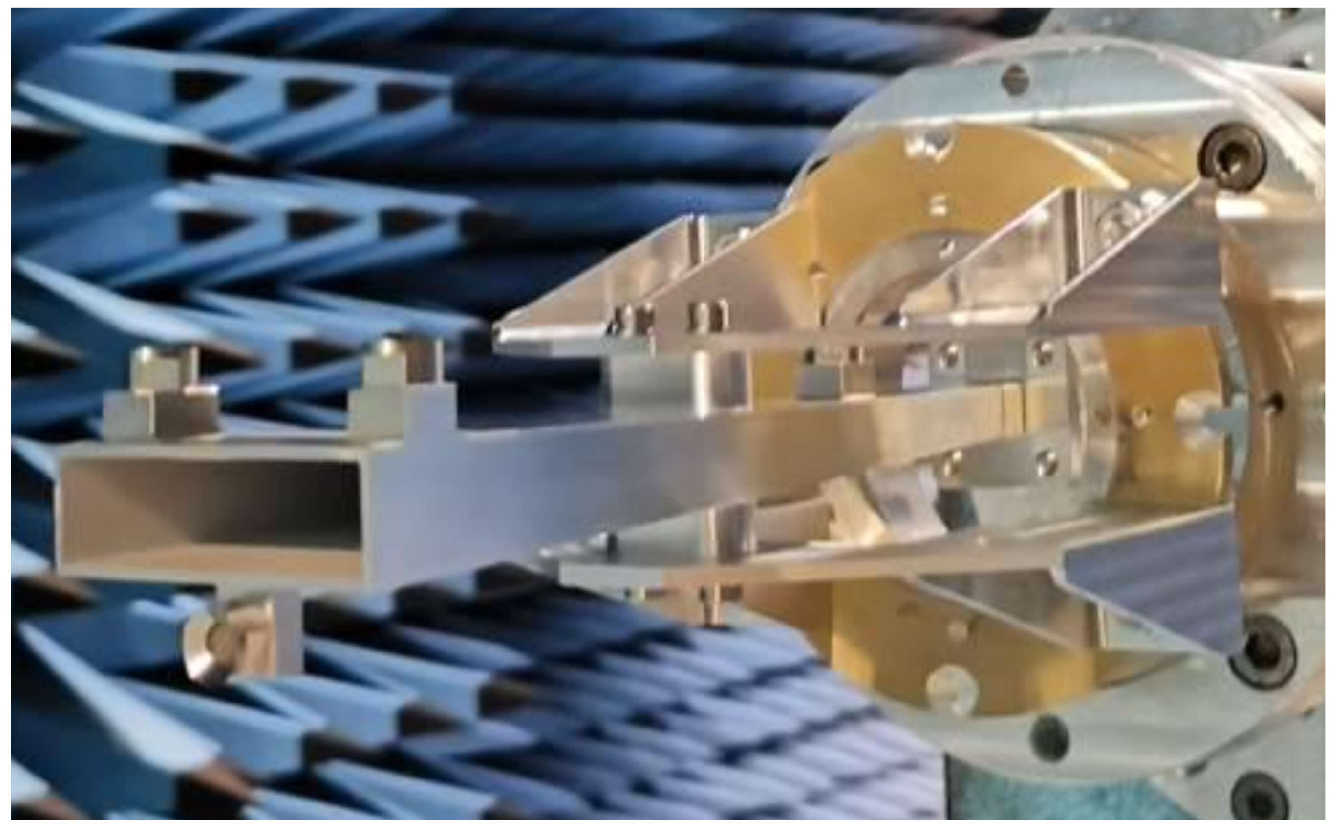
The manufactured feed, as positioned in the measurement chamber, is shown in
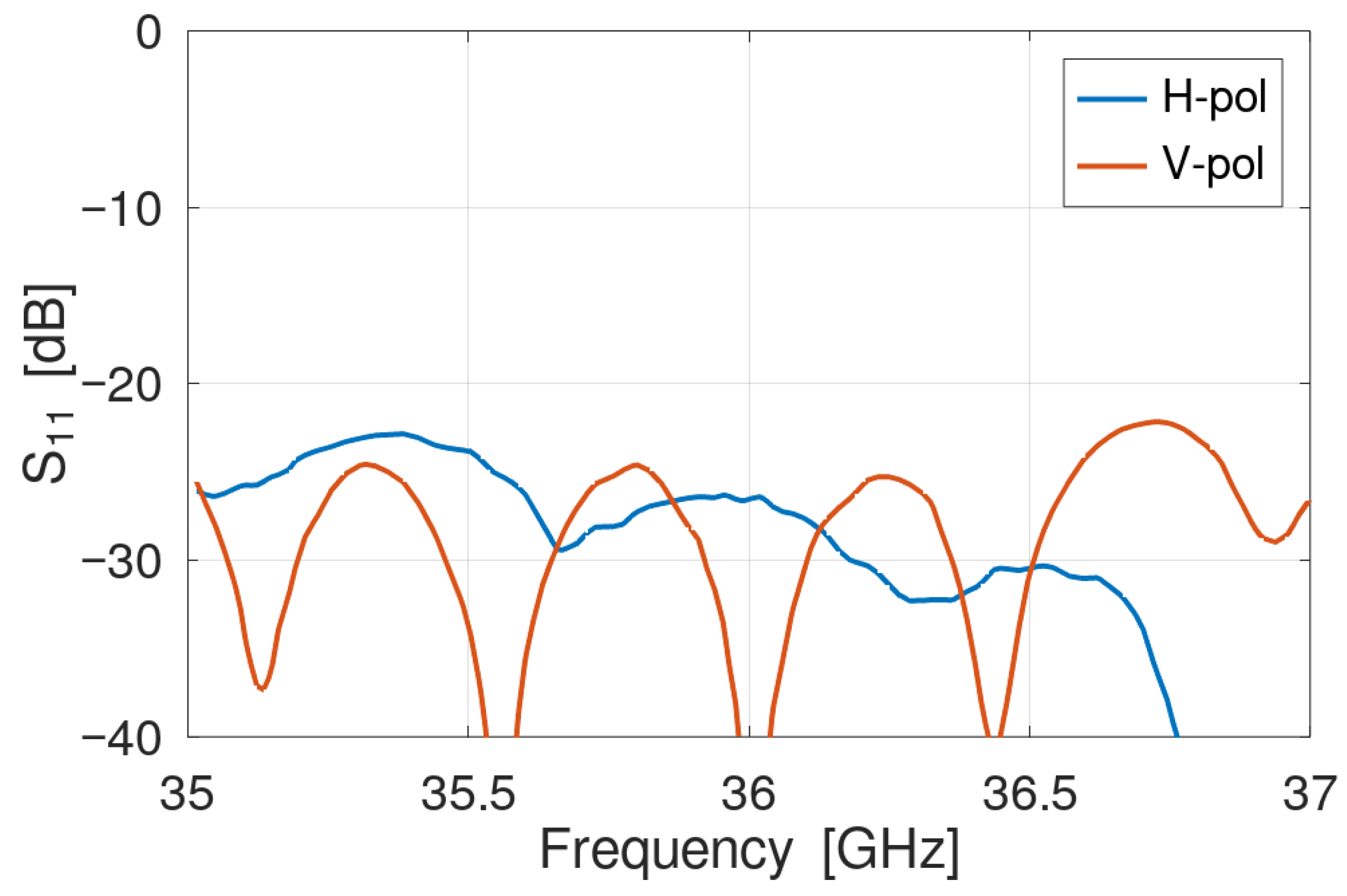
Figure 4. Three optical pinballs are visible near the horn aperture; these are included solely for measurement purposes and will not be part of the feed in the final reflectarray antenna system. To verify that their presence does not adversely affect the assessment of feed performance, detailed full-wave electromagnetic simulations were performed using CAD models of the fabricated feed, both with and without the optical sensors. The comparison confirmed that the sensors have a negligible impact on the feed’s radiation patterns. The measured reflection coefficient for the two polarization modes remains well below −20 dB in the entire band—see
Figure 5. The horn has a main beam directivity around 20.0 dBi and 20.4 dBi for the vertical and horizontal polarizations, respectively, as detailed in
Table 2. Furthermore, an on-axis XPD better than 30 dB is obtained throughout the frequency band in both polarization modes.
2.3. Reflectarray Panel Design
The reflectarray was designed using the QUPES software tool [
21], employing a direct optimization strategy in which all elements are simultaneously optimized to meet the specified radiation pattern requirements [
22], without placing emphasis on intermediate quantities such as the individual element phase responses. The analysis is based on a local periodicity approach using a periodic MoM solver. More information about the analysis and optimization method can be found in [
22].
To fulfill the pattern specifications, a polarization-selective reflectarray is required, meaning that the response of the reflectarray must depend on the polarization of the incident field.
Several reflectarray configurations applicable to Ka-band were investigated, including both single-layer and multilayer designs. While many of these configurations showed promising performance, a single-layer design was selected for further development due to its simplicity in manufacturing.
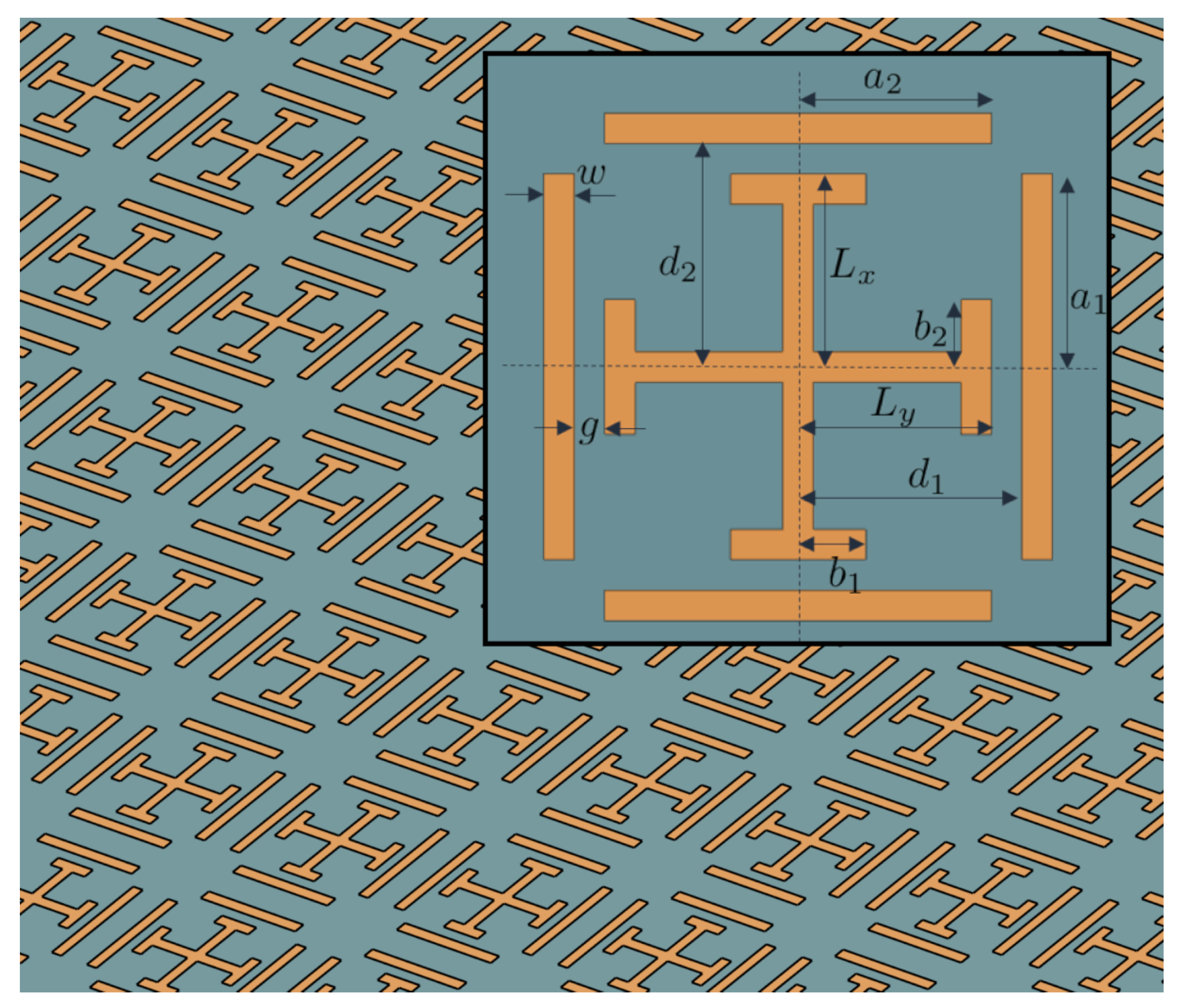
The final reflectarray comprises approximately 71,000 elements, implemented on aRogers 6002 substrate with a thickness of 0.762 mm. The selected element geometry is a Jerusalem Cross with an open quadratic loop [
23], arranged in unit cells measuring 3.4 mm × 3.4 mm, as shown in
Figure 6. This element provides a near-linear phase response—see
Figure 7—with low mutual coupling between two orthogonal linear polarizations, making it suitable for dual-polarization applications. Although several geometric parameters could be subject to optimization—see
Table 3—only the two lengths
and
are varied, reducing the number of optimization variables to approximately 142,000 (71,000 × 2). For many optimization methods, handling such a large number of variables can be challenging. However, QUPES is specifically developed for the design of these structures and incorporates specialized optimization algorithms for this purpose [
24]. Consequently, optimization problems of this scale do not pose a difficulty when using QUPES.
To ensure mechanical stability, the reflectarray panel is constructed as a sandwich structure consisting of high modulus CFRP skins and a lightweight 70 mm aluminum honeycomb core. The complete panel stack-up is shown in
Figure 8. The simplicity of the design enables the use of standard metallization processes, tools, and techniques available at Airbus Space Systems Spain.
2.4. Thermo-Mechanical Analysis
Focusing on the thermal design, one of the principal trade-offs carried out consisted of determining whether the use of sunshield would be compatible with both accommodation feasibility and TED performance.
With respect to the thermal analysis, two different thermal models have been created: the first one considers sunshield, in opposition to another thermal model without any sunshield. The sunshield provides a preliminary protective layer that helps to reduce gradients and the possibility of hot spots. However, a design without any sunshield eases the folding of the different elements. Based on both geometrical and thermal mathematical models, it was decided that the baseline is to proceed without sunshield. With respect to the mechanical analysis, a set of different analyses was performed, including, e.g., Quasi Static analysis, sinusoidal analysis, random analysis, and acoustic and thermo-elastic distortion (TED) analysis.
In relation to TED, the distortion surfaces have been included in the RF analysis of the antenna system. The results showed that the worst case degradation is less than 0.1 dB, implying that the TED has a small impact on the reflectarray patterns.
3. Reflectarray Performance
Simulation results for the subreflector/reflectarray system performance under illumination from the measured feed patterns were simulated using GRASP [
25], in conjunction with QUPES. The measured feed patterns were represented by spherical wave expansions (SWE), which illuminate the subreflector. The subreflector, which is analyzed using Physical Optics (PO) in GRASP, then reflects the field toward the reflectarray panel, yielding the final radiated field.
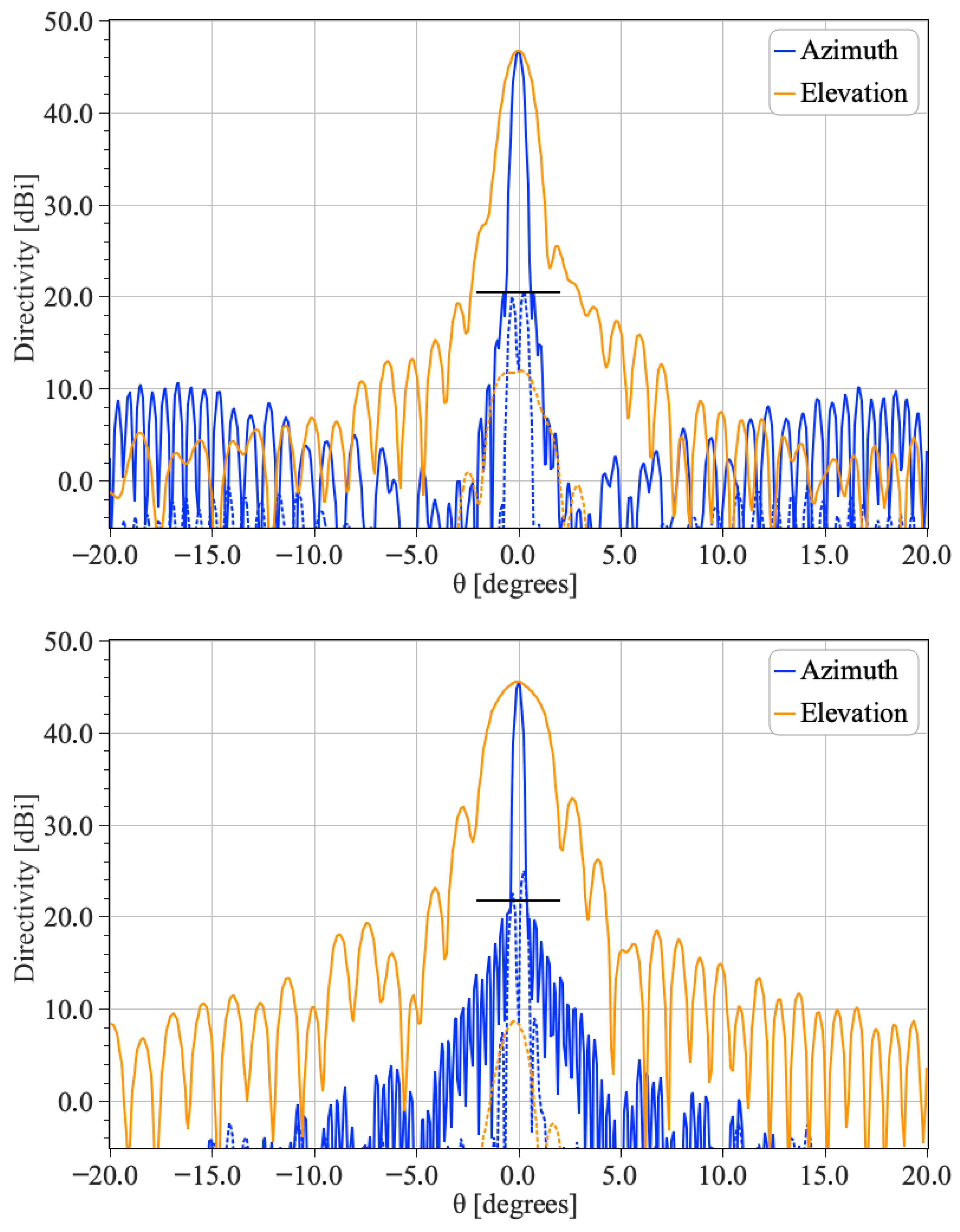
Figure 9 shows the simulated radiation patterns of the reflectarray antenna at the center frequency of 35.75 GHz for both the high-resolution and low-resolution configurations (top and bottom panels, respectively). The corresponding pattern characteristics like peak gain, sidelobe level (SLL), half-power beamwidth (HPBW), and on-axis cross polar discrimination (XPD) values at all three simulated frequencies are summarized in
Table 4. The Table shows that the design is able to achieve the desired requirements for both the operative modes and for all the operative frequencies. The gain variation over the operative bandwidth is around 0.2 dB, and the HPBW and SLL are stable for with minimal variation across the observed frequencies.
For the high-resolution case, a minimum gain requirement of 46.7 dBi is imposed. The current design, based on the measured sectoral horn, reaches this target with little margin. In the low-resolution configuration, the gain slightly exceeds the specified requirement. Radiation patterns at the other two frequencies were found to be similar and are therefore omitted for brevity.
A comparison with simulations using an idealized feed model indicates a gain reduction of approximately 0.6 dB in both polarizations when using the measured sectoral horn. This degradation is attributed to less optimal illumination of the subreflector and increased spillover losses.
To improve the gain margin, the reflectarray panel dimensions could be marginally increased. Alternatively, a feed with a more favorable illumination profile could also enhance overall system performance.
4. BBM Manufacturing and Assembly
The manufacturing of the Breadboard Model (BBM) comprised two main components: the manufacturing of the Mechanical Ground Support Equipment (MGSE) and the fabrication of the reflectarray antenna, with the latter representing the most critical aspect of the project. Multiple fabrication trials were conducted in collaboration with the supplier to ensure that the etching tolerances, both in absolute dimensions and in element positioning, met the specified requirements.
Given the large physical dimensions of the antenna, the reflectarray panel was assembled from four individual PCB segments of varying sizes. Consequently, cutting tolerances during board preparation also contribute to overall manufacturing uncertainty.
For the BBM, the subreflector mirror was fabricated from Al-7075 aluminium to simplify the design and manufacturing process. Both the main reflectarray panel and the subreflector include pinball alignment items. These not only facilitate precise positioning during antenna integration but also enable accurate alignment verification during RF testing, ensuring the correct positioning of the components in the measurement anechoic chamber.
The alignment process of MASKARA BBM follows the following sequence:
Installation of the Main panel on the MGSE.
Alignment of the flat subreflector with respect to the main reflector/panel.
Alignment of the feeder with respect to the main reflector
After integrating the BBM, a tolerance analysis was performed focusing on the primary contributors: alignment and manufacturing tolerances.
The components were assembled using a laser tracker and six-axis robots to ensure the specified tolerances. Because the antenna’s size and geometry precluded direct alignment, the alignment sequence was carefully analyzed. This study showed that two laser trackers were required to characterize the entire structure simultaneously. The final assembly achieved the required ±0.1 mm tolerance.
In addition, feed alignment tolerances of ±0.2 mm and feed rotation tolerances of ±0.1° were achieved. This results in a degradation of the peak gain less than 0.2 dB. The degradation is mainly due to cross-polarization and beam-shape distortion. In terms of mis-pointing, the worst case was found to be around 0.025°.
A manufacturing tolerance of ±0.02mm was achieved, determined by the etching and plate-cutting tolerances of the array elements. Uncertainty quantification using UQ [
26] showed that this tolerance can reduce the peak gain and distort the beam shape by up to 0.29 dB.
A CAD model of the complete BBM, including the MGSE, is shown in
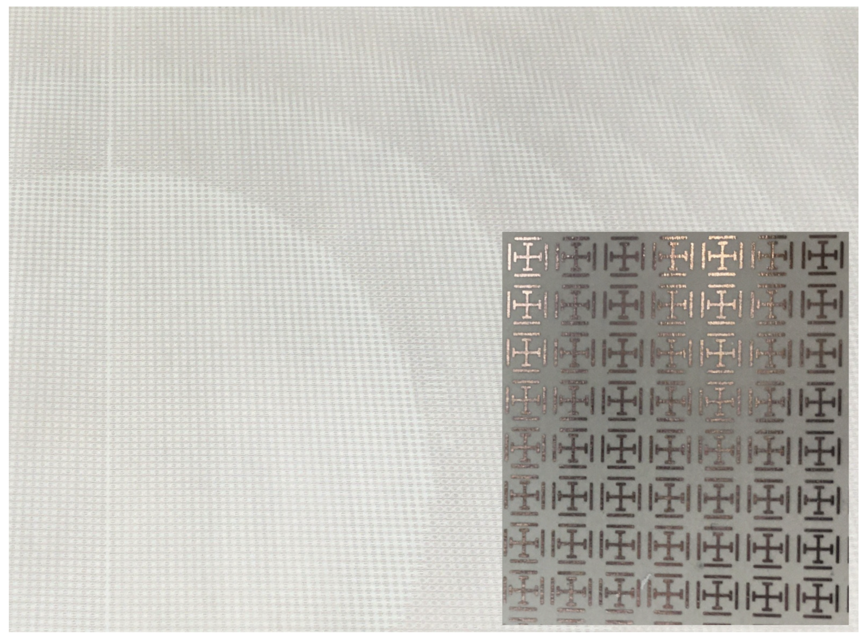
Figure 10, while a detailed photograph of the manufactured reflectarray panel is provided in
Figure 11.
5. Experimental Validation
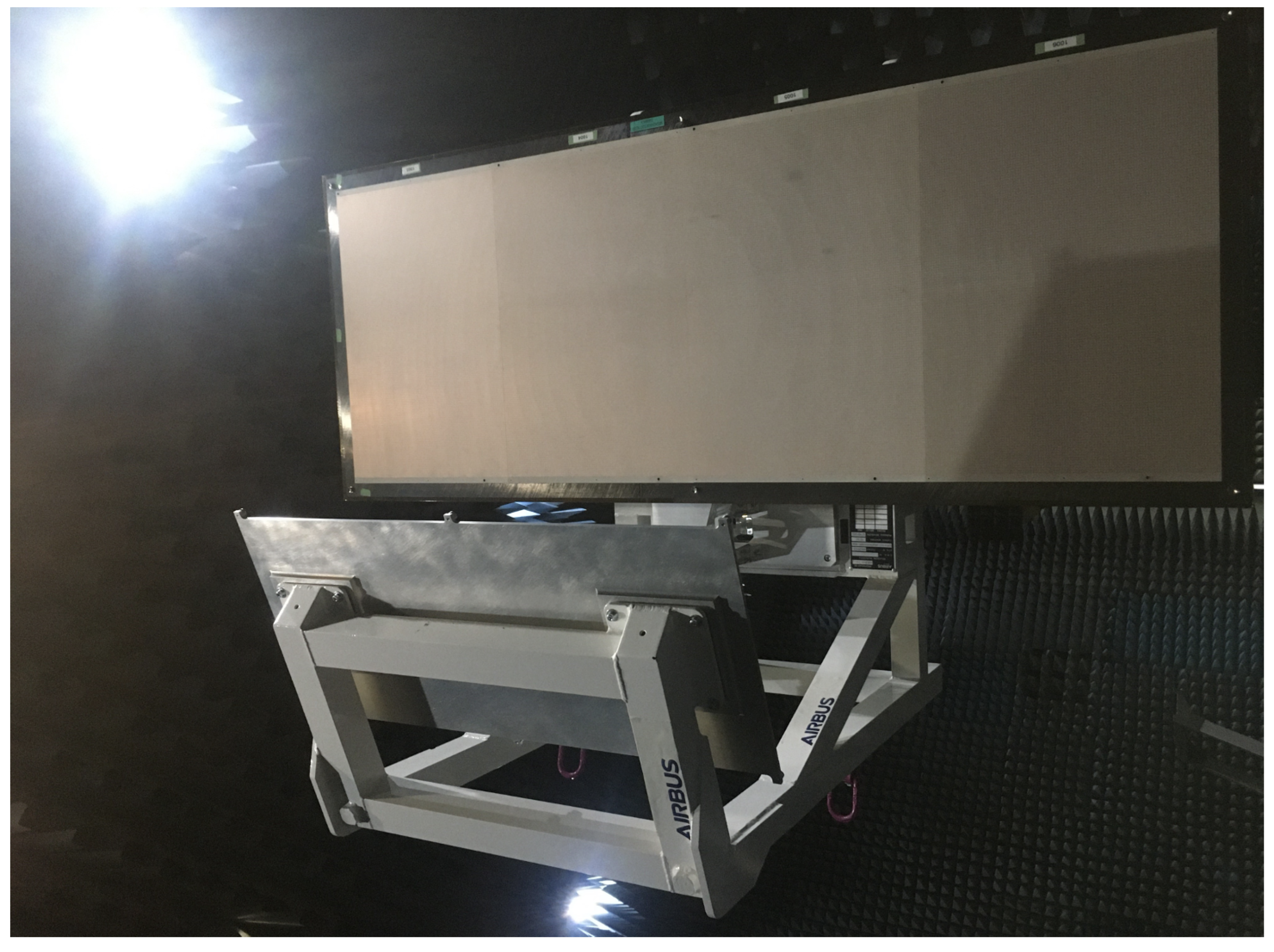
The test campaign for the Breadboard Model (BBM) focused on measuring the radiation patterns at 35.5 GHz, 35.75 GHz, and 36.0 GHz for the two operational modes. Prior to full system integration, a preliminary measurement of the feed subassembly was conducted to validate the feed design. The RF tests were carried out by Airbus Space Systems Spain by using a planar scanner at their facilities in Madrid, as shown in
Figure 12.
The antenna model used for correlation with measurements included the scattering contributions from the MGSE, as well as the effects of manufacturing, etching, and assembly tolerances. As a result, the simulated performance exhibits a slight degradation compared to the ideal case presented in
Section 3.
Figure 13 presents the measured (solid red) and simulated (dashed black) radiation patterns at 35.50 GHz, 35.75 GHz, and 36.00 GHz, for both the high- and low-resolution modes. The contour levels correspond to −3, −5, −10, −15, −20, −25, and −30 dB relative to the peak. A close agreement is observed between the simulated and measured contours. Additionally, the reflectarray demonstrates the intended behavior of producing distinct beamwidths for the two orthogonal polarizations, thereby validating its dual-mode operation.
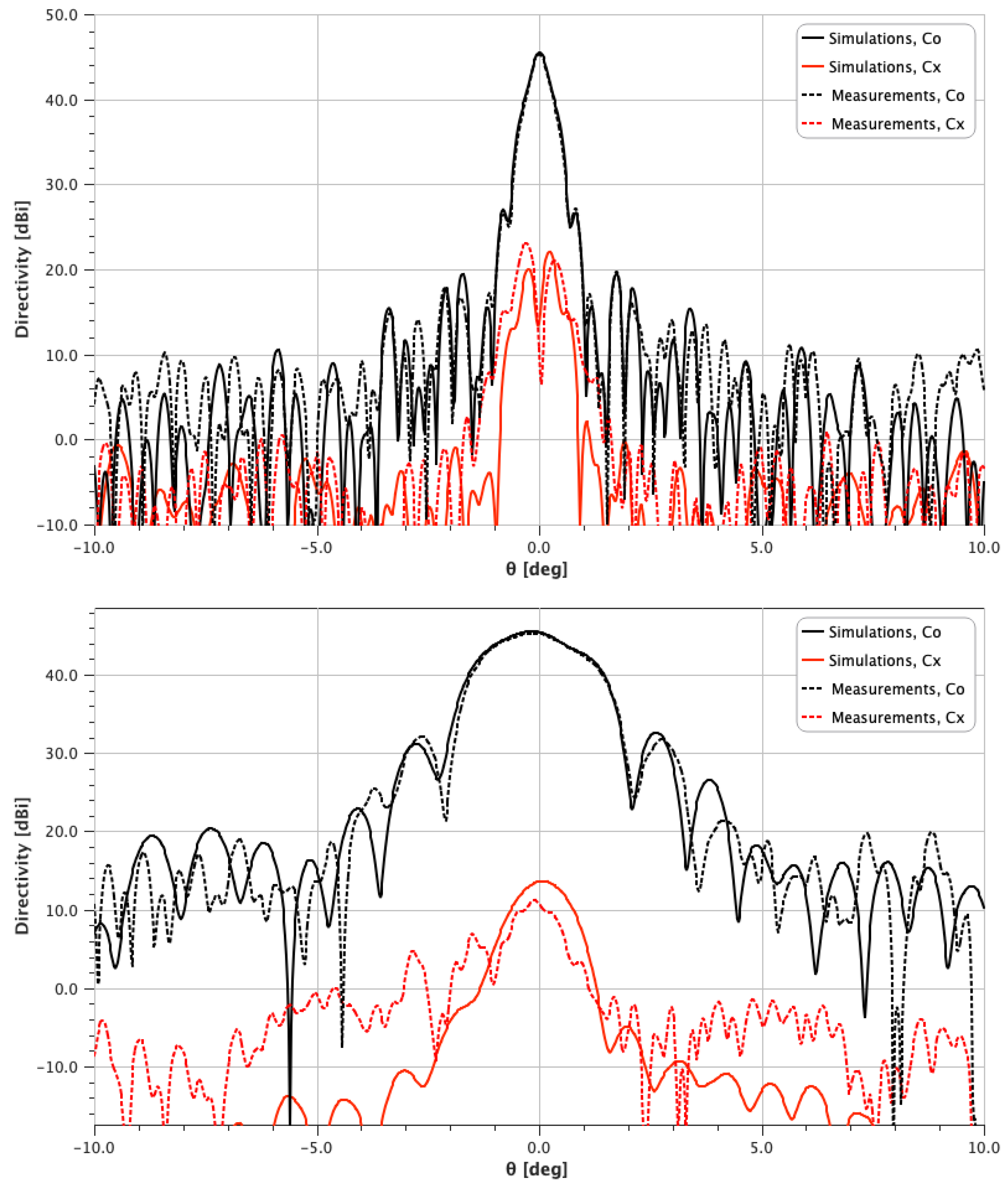
The cross-polarization results are presented in
Figure 14, which shows the simulated and measured radiation patterns at 36 GHz for the low-resolution operation mode. The cross-polarization level is approximately 25 dB below the main lobe peak, and a good agreement between simulation and measurement is observed. 1D Patterns at the other frequencies and for the high-resolution mode are not shown, as they exhibit similar characteristics.
Table 5 summarizes the measured and simulated directivity values for both operational modes. The maximum deviation between simulation and measurement is below 0.4 dB, which falls within the combined uncertainty margin of the simulation and measurement processes.
Gain measurements were not conducted during the experimental tests, so no measured loss values are available. However, simulations estimate the following losses:
Material losses between 0.2 and 0.4 dB.
Feed alignment and rotation 0.17 dB.
Manufacturing errors 0.29 dB.
The results presented in this paper demonstrate the viability of the proposed concept and confirm that the reflectarray antenna can achieve the dual-mode performance required for high-resolution and wide-swath SAR operation. This validates the suitability of reflectarray technology as a promising and practical solution for future real-spaceborne SAR missions operating in Ka-band.
6. Conclusions
This paper has presented the design, implementation, and experimental validation of a dual-offset reflectarray antenna system for a high-resolution and wide-swath SAR instrument operating in Ka-band. The antenna supports two operational modes: a high-resolution mode with a highly directive beam in one linear polarization, and a low-resolution mode with a broader beam in the orthogonal polarization. The feed system, consisting of a sectoral horn illuminating a planar subreflector, enables efficient excitation of the main reflectarray panel with dimensions of 1.5 m × 0.55 m. The reflectarray meets the RF performance requirements across the operational frequency band of 35.5–35.6 GHz. A breadboard model of the system was successfully manufactured and experimentally tested. The excellent agreement observed between simulations and measurements confirms both the accuracy of the modeling approach and the robustness of the fabrication process, thereby demonstrating the feasibility of using reflectarray technology for future spaceborne SAR missions. Based on the successful validation of the breadboard model under relevant laboratory conditions, Technology Readiness Level 4 (TRL-4) has been achieved.
Author Contributions
Conceptualization, M.Z., D.M., and G.T.; methodology, M.Z., D.M., N.V., M.F.P., and S.B.S.; software, M.Z., P.G.N., N.V., M.F.P., and S.B.S.; validation, M.Z., P.G.N., D.M., and J.H.; formal analysis, M.Z., P.G.N., N.V., M.F.P., and S.B.S.; investigation, M.Z., P.G.N., N.V., M.F.P., and S.B.S.; resources, M.Z., D.M., and G.T.; data curation, P.G.N., J.H., N.V., M.F.P., and S.B.S.; writing—original draft preparation, M.Z.; writing—review and editing, M.Z., P.G.N., D.M., and G.T.; visualization, M.Z., and P.G.N.; supervision, M.Z., D.M., and G.T.; project administration, M.Z., D.M., and G.T.; funding acquisition, M.Z., D.M., and G.T. All authors have read and agreed to the published version of the manuscript.
Funding
ESA contract No. 4000126144/18/NL/AF.
Data Availability Statement
The original contributions presented in this study are included in the article. Further inquiries can be directed to the corresponding author.
Conflicts of Interest
Authors Min Zhou, Pasquale G. Nicolaci, Javier Herreros, Niels Vesterdal, Michael F. Palvig and Stig B. Sørensen were employed by the company TICRA; Authors David Marote and Javier Herreros were employed by the company Airbus Defence and Space SAU. The remaining authors declare that the research was conducted in the absence of any commercial or financial relationships that could be construed as a potential conflict of interest.
References
- Curlander, J.C.; McDonough, R.N. Synthetic Aperture Radar: Systems and Signal Processing; Wiley-Interscience: Hoboken, NJ, USA, 1991. [Google Scholar]
- Song, R.; Wang, W.; Yu, W. The Latest Developments in Spaceborne High-Resolution Wide-Swath SAR Systems and Imaging Methods. Sensors 2024, 24, 5978. [Google Scholar] [CrossRef] [PubMed]
- Gebert, N.; Krieger, G.; Moreira, A. Multichannel Azimuth Processing in ScanSAR and TOPS Mode Operation. IEEE Trans. Geosci. Remote Sens. 2010, 48, 2994–3008. [Google Scholar] [CrossRef]
- Mapelli, D.; Guccione, P.; Giudici, D.; Stasi, M.; Imbembo, E. Generalization of the Synthetic Aperture Radar Azimuth Multi-Aperture Processing Scheme—MAPS. Remote Sens. 2024, 16, 3170. [Google Scholar] [CrossRef]
- Rubio, A.J.; Kaddour, A.S.; Ynchausti, C.; Magleby, S.; Howell, L.L.; Georgakopoulos, S.V. A Foldable Reflectarray on a Hexagonal Twist Origami Structure. IEEE Open J. Antennas Propag. 2021, 2, 1108–1119. [Google Scholar] [CrossRef]
- Kaddour, A.S.; Velez, C.A.; Hamza, M.; Brown, N.C.; Ynchausti, C.; Magleby, S.P.; Howell, L.L.; Georgakopoulos, S.V. A Foldable and Reconfigurable Monolithic Reflectarray for Space Applications. IEEE Access 2020, 8, 219355–219366. [Google Scholar] [CrossRef]
- Hodges, R.E.; Chahat, N.; Hoppe, D.J.; Vacchione, J.D. A Deployable High-Gain Antenna Bound for Mars: Developing a new folded-panel reflectarray for the first CubeSat mission to Mars. IEEE Antennas Propag. Mag. 2017, 59, 39–49. [Google Scholar] [CrossRef]
- Huang, J.; Encinar, J.A. Reflectarray Antennas; IEEE Press: New York, NY, USA, 2008. [Google Scholar]
- Pozar, D.M.; Targonski, S.D.; Syrigos, H.D. Design of millimeter wave microstrip reflectarrays. IEEE Trans. Antennas Propag. 1997, 45, 287–296. [Google Scholar] [CrossRef]
- Shaker, J.; Cuhaci, M. Multi-band, multi-polarisation reflector-reflectarray antenna with simplified feed system and mutually independent radiation patterns. Proc. Inst. Elect. Eng. Microw. Antennas Propag. 2005, 152, 97–101. [Google Scholar] [CrossRef]
- Zhou, M.; Sørensen, S.B.; Brand, Y.; Toso, G. Doubly curved reflectarray for dual-band multiple spot beam communication satellites. IEEE Trans. Antennas Propag. 2019, 68, 2087–2096. [Google Scholar] [CrossRef]
- de Rioja, D.M.; de Rioja, E.M.; Rodriguez-Vaqueiro, Y.; Encinar, J.A.; Pino, A.; Arias, M.; Toso, G. newblock Transmit–Receive Parabolic Reflectarray to Generate Two Beams per Feed for Multispot Satellite Antennas in Ka-Band. IEEE Trans. Antennas Propag. 2020, 69, 2673–2685. [Google Scholar] [CrossRef]
- Encinar, J.A.; Datashvili, L.S.; Zornoza, J.A.; Arrebola, M.; Sierra-Castaner, M.; Besada-Sanmartin, J.L.; Baier, H.; Legay, H. Dual-Polarization Dual-Coverage Reflectarray for Space Applications. IEEE Trans. Antennas Propag. 2006, 54, 2827–2837. [Google Scholar] [CrossRef]
- Pan, X.; Yang, F.; Xu, S.; Li, M. A 10 240-Element Reconfigurable Reflectarray with Fast Steerable Monopulse Patterns. IEEE Trans. Antennas Propag. 2021, 69, 173–181. [Google Scholar] [CrossRef]
- Xi, B.; Xiao, Y.; Zhu, K.; Liu, Y.; Sun, H.; Chen, Z. 1-Bit Wideband Reconfigurable Reflectarray Design in Ku-Band. IEEE Access 2022, 10, 4340–4348. [Google Scholar] [CrossRef]
- Bouslama, M.; Clemente, A. Dual-Band Unit Cell for Electronically Reconfigurable Reflectarrays at mmWave. In Proceedings of the 2024 IEEE International Symposium on Antennas and Propagation and INC/USNC-URSI Radio Science Meeting (AP-S/INC-USNC-URSI), Firenze, Italy, 14–19 July 2024; pp. 2419–2420. [Google Scholar] [CrossRef]
- Hodges, R.E.; Chen, J.; Radway, M.; Amaro, L.; Khayatian, B.; Munger, J. An extremely large Ka-band reflectarray antenna for interferometric SAR. IEEE Antennas Propag. Mag. 2020, 62, 23–33. [Google Scholar] [CrossRef]
- Vesterdal, N.; Zhou, M.; Palvig, M.F.; Sørensen, S.B.; de Lasson, J.R.; Alvarez, D.M.; Toso, G. RF Modeling and Measurements of a Reflectarray for Synthetic Aperture Radar for Earth Observations. In Proceedings of the EuCAP, Madrid, Spain, 27 March–1 April 2022. [Google Scholar]
- Tienda, C.; Younis, M.; Lopez-Dekker, P.; Laskowski, P. Ka-band reflectarray antenna system for SAR applications. In Proceedings of the EuCAP, The Hague, The Netherlands, 6–11 April 2014. [Google Scholar]
- ESTEAM Software, TICRA: Copenhagen, Denmark. Available online: https://www.ticra.com/ (accessed on 1 September 2025).
- QUPES Software, TICRA: Copenhagen, Denmark. Available online: https://www.ticra.com/ (accessed on 1 September 2025).
- Zhou, M.; Sørensen, S.B.; Kim, O.S.; Jørgensen, E.; Meincke, P.; Breinbjerg, O. Direct Optimization of Printed Reflectarrays for Contoured Beam Satellite Antenna Applications. IEEE Trans. Antennas Propag. 2013, 61, 1995–2004. [Google Scholar] [CrossRef]
- Wu, G.; Qu, S.; Yang, S.; Chan, C.H. Broadband, Single-Layer Dual Circularly Polarized Reflectarrays with Linearly Polarized Feed. IEEE Trans. Antennas Propag. 2016, 64, 4235–4241. [Google Scholar] [CrossRef]
- Zhou, M.; Jørgensen, E.; Vesterdal, N.; Borries, O.; Sørensen, S.B.; Meincke, P.; Simeoni, M.; Toso, G. Design of High-Performance Antenna Systems with Quasi-Periodic Surfaces. In Proceedings of the EuCAP, London, UK, 9–13 April 2018. [Google Scholar]
- GRASP Software, TICRA: Copenhagen, Denmark. Available online: https://www.ticra.com/ (accessed on 1 September 2025).
- UQ Software, TICRA: Copenhagen, Denmark. Available online: https://www.ticra.com/ (accessed on 1 September 2025).
Figure 1.
Spacecraft scheme with nine dual-offset reflectarray panels.
Figure 1.
Spacecraft scheme with nine dual-offset reflectarray panels.
Figure 2.
MASKARA and S/C accommodation in Vega-C launcher in stowed configuration.
Figure 2.
MASKARA and S/C accommodation in Vega-C launcher in stowed configuration.
Figure 3.
Simulation model of the sectoral horn feed. The shown model is associated to the vertical polarization mode. A corresponding model with orthogonal port orientation was used for the opposite polarization.
Figure 3.
Simulation model of the sectoral horn feed. The shown model is associated to the vertical polarization mode. A corresponding model with orthogonal port orientation was used for the opposite polarization.
Figure 4.
The sectoral horn feed situated in a spherical near-field measurement setup.
Figure 4.
The sectoral horn feed situated in a spherical near-field measurement setup.
Figure 5.
Measured reflection coefficients over the operative bandwidth.
Figure 5.
Measured reflection coefficients over the operative bandwidth.
Figure 6.
Close-up view of the reflectarray panel simulation model with insert showing the Jerusalem Cross with open loop element. The quantities and have been optimised and vary for each element. The remaining quantities are fixed.
Figure 6.
Close-up view of the reflectarray panel simulation model with insert showing the Jerusalem Cross with open loop element. The quantities and have been optimised and vary for each element. The remaining quantities are fixed.
Figure 7.
Phase response for the TM polarization of the periodic unit cell compared with linear approximation.
Figure 7.
Phase response for the TM polarization of the periodic unit cell compared with linear approximation.
Figure 8.
Reflectarray panel sandwich stack-up.
Figure 8.
Reflectarray panel sandwich stack-up.
Figure 9.
Simulated radiation patterns based on measured patterns of the sectoral feed horn.
Top: High-resolution mode;
bottom: Low-resolution mode. The black bars signify the cross-polar limits due to the XPI requirements in
Table 1.
Figure 9.
Simulated radiation patterns based on measured patterns of the sectoral feed horn.
Top: High-resolution mode;
bottom: Low-resolution mode. The black bars signify the cross-polar limits due to the XPI requirements in
Table 1.
Figure 10.
CAD model of the entire BBM.
Figure 10.
CAD model of the entire BBM.
Figure 11.
Photo of the manufactured reflectarray panel.
Figure 11.
Photo of the manufactured reflectarray panel.
Figure 12.
BBM in the Airbus Spain anechoic chamber.
Figure 12.
BBM in the Airbus Spain anechoic chamber.
Figure 13.
Simulated (dashed black) and measured (solid red) radiation pattern at (a) 35.50 GHz, 35.75 GHz, and 36.00 GHz for the two operation modes, (a–c) High Resolution and (d–f) Low Resolution. The contours represent −3, −5, −10, −15, −20, −25, and −30 dB below peak.
Figure 13.
Simulated (dashed black) and measured (solid red) radiation pattern at (a) 35.50 GHz, 35.75 GHz, and 36.00 GHz for the two operation modes, (a–c) High Resolution and (d–f) Low Resolution. The contours represent −3, −5, −10, −15, −20, −25, and −30 dB below peak.
Figure 14.
Simulated (solid) and measured (dashed) radiation pattern at 36.0 GHz for low-resolution mode. (Top): Azimuth, (bottom): Elevation.
Figure 14.
Simulated (solid) and measured (dashed) radiation pattern at 36.0 GHz for low-resolution mode. (Top): Azimuth, (bottom): Elevation.
Table 1.
Pattern requirements.
Table 1.
Pattern requirements.
| Frequency band |
| 35.5–36.0 GHz |
| High-resolution mode |
| Polarization | x-pol. |
| Antenna gain | >46.7 dBi |
| HPBW azimuth | 0.33° |
| HPBW elevation | 1.2° |
| Low-resolution mode |
| Polarization | y-pol. |
| Antenna gain | >45.2 dBi |
| HPBW azimuth | 0.33° |
| HPBW elevation | 2.4° |
| Side-lobe level (SLL) requirements (gain mask) |
| [°] | Gain [dBi] |
| 1.5 | 41.5 |
| 1.8 | 38.5 |
| 2.5 | 32.0 |
| 5.0 | 25.0 |
| 10.0 | 20.0 |
| Cross-polar requirements |
| XPI | 25 dB |
Table 2.
Measured feed pattern characteristics.
Table 2.
Measured feed pattern characteristics.
| Frequency | Directivity | On-Axis XPD |
|---|
| Horizontal pol. |
| 35.50 GHz | 19.9 dBi | 35 dB |
| 35.75 GHz | 20.1 dBi | 35 dB |
| 36.00 GHz | 20.1 dBi | 34 dB |
| Vertical polarization |
| 35.50 GHz | 20.3 dBi | 37 dB |
| 35.75 GHz | 20.5 dBi | 34 dB |
| 36.00 GHz | 20.4 dBi | 33 dB |
Table 3.
Unit cell fixed geometrical parameters.
Table 3.
Unit cell fixed geometrical parameters.
| Parameter | Value [mm] | Parameter | Value [mm] |
|---|
| 0.9025 | | 0.9025 |
| 0.3325 | | 0.3325 |
| 1.1500 | | 1.1500 |
| g | 0.2000 | w | 0.2000 |
Table 4.
Reflectarray pattern characteristics.
Table 4.
Reflectarray pattern characteristics.
| Frequency | 35.50 GHz | 35.75 GHz | 36.0 GHz | Requirements |
|---|
| Gain, HR | 46.7 dBi | 46.7 dBi | 46.7 dBi | 46.7 dBi |
| Gain, LR | 45.3 dBi | 45.5 dBi | 45.4 dBi | 45.2 dBi |
| SLL azimuth, HR | >28.2 dB | >26.3 dB | >33.4 dB | Table 1 |
| SLL elevation, HR | >20.5 dB | >21.4 dB | >19.4 dB | Table 1 |
| SLL azimuth, LR | >24.2 dB | >25.6 dB | >25.4 dB | Table 1 |
| SLL elevation, LR | >13.13 dB | >12.5 dB | >12.80 dB | Table 1 |
| HPBW azimuth, HR | 0.46 deg | 0.47 deg | 0.47 deg | 0.33 deg |
| HPBW elevation, HR | 1.22 deg | 1.22 deg | 1.20 deg | 1.20 deg |
| HPBW azimuth, LR | 0.35 deg | 0.34 deg | 0.35 deg | 0.33 deg |
| HPBW elevation, LR | 2.10 deg | 2.40 deg | 2.25 deg | 2.40 deg |
| XPD, HR | 37.8 dB | 40 dB | 33.4 dB | 25 dB |
| XPD, LR | 37.2 dB | 35.6 dB | 33.3 dB | 25 dB |
Table 5.
Measured directivity.
Table 5.
Measured directivity.
| Low-Resolution Mode |
| Frequency | Meas. | Simulation |
| [dBi] | [dBi] |
| 35.50 | 46.6 | 47.0 |
| 35.75 | 46.2 | 46.3 |
| 36.00 | 45.3 | 45.5 |
| High-Resolution Mode |
| Frequency | Meas. | Simulation |
| [dBi] | [dBi] |
| 35.50 | 47.8 | 48.1 |
| 35.75 | 47.7 | 47.9 |
| 36.00 | 47.4 | 47.6 |
| Disclaimer/Publisher’s Note: The statements, opinions and data contained in all publications are solely those of the individual author(s) and contributor(s) and not of MDPI and/or the editor(s). MDPI and/or the editor(s) disclaim responsibility for any injury to people or property resulting from any ideas, methods, instructions or products referred to in the content. |
© 2025 by the authors. Licensee MDPI, Basel, Switzerland. This article is an open access article distributed under the terms and conditions of the Creative Commons Attribution (CC BY) license (https://creativecommons.org/licenses/by/4.0/).
