Article

Wideband Multi-Layered Dielectric Resonator Antenna with Small Form Factor for 5G Millimeter-Wave Mobile Applications

Electronic Component Design Lab, Samsung Electro-Mechanics, Suwon 16674, Republic of Korea
*
Author to whom correspondence should be addressed.
Electronics 2025, 14(19), 3756; https://doi.org/10.3390/electronics14193756
Submission received: 24 August 2025 / Revised: 19 September 2025 / Accepted: 22 September 2025 / Published: 23 September 2025
(This article belongs to the Section Electronic Materials, Devices and Applications)

Abstract

A ceramic-based wideband capacitive-fed patch-loaded multi-layered rectangular dielectric resonator antenna (CFPL-ML-RDRA) with a compact form factor is proposed in this paper. The proposed antenna is composed of two ceramic substrates and a polymer as an adhesive. A capacitive-fed metallic patch structure is located on the top side of the bottom ceramic substrate. This novel structure generates two distinct resonant modes: the fundamental resonant mode of the RDRA and a hybrid resonant mode, which was confirmed through electric field (E-field) analysis and parametric studies. By merging these two resonant modes, the proposed antenna achieves a wide impedance bandwidth of 5.5 GHz, sufficient to cover the fifth-generation (5G) millimeter-wave (mmWave) frequency bands n257, n258, and n261 (5.25 GHz), while reducing the height of the DRA by 38.5% compared to the conventional probe-fed RDRA (PF-RDRA). Additionally, the 4 dBi realized gain bandwidth of the proposed CFPL-ML-RDRA is 5.4 GHz, which is 28.6% broader than that of the conventional PF-RDRA. To experimentally verify the antenna’s performance, the CFPL-ML-RDRA mounted on a test printed circuit board with a small ground size of 3.2 × 3.2 mm2 was fabricated and characterized. The measured data align well with the simulated data. Furthermore, excellent antenna array performance was achieved based on array simulations. Therefore, the proposed antenna structure is well-suited for 5G mmWave mobile applications.

1. Introduction

To fully leverage the capabilities of fifth-generation (5G) mobile wireless communication systems, including extremely high data rates, large capacity, and low latency, millimeter-wave (mmWave) wireless communication is essential [1,2,3,4,5,6]. The 5G new radio (NR) mmWave frequency bands, designated as frequency range 2 (FR2), span a wide spectrum from 24.25 GHz to 52.6 GHz [6]. Within FR2, the n257 (26.5~29.5 GHz), n258 (24.25~27.5 GHz), and n261 (27.5~28.35 GHz) bands are predominantly allocated by many countries. To cover these FR2 bands with a single radiator, the antenna or antenna array must achieve a fractional bandwidth (FBW) greater than 19.5%. Additionally, a relatively high antenna gain is required to compensate for the significant atmospheric path loss at FR2 during electromagnetic (EM) wave propagation. Furthermore, enabling polarization diversity through dual-polarized antennas and increasing the number of 5G mmWave antenna front-end modules (FEMs) in modern mobile handsets are crucial for enhancing the reliability of wireless communication [7]. Consequently, there is a strong demand for compact 5G mmWave antenna FEMs to accommodate the limited space in smartphones and provide greater design flexibility.
To address these requirements and challenges, the dielectric resonator antenna (DRA) emerges as an ideal solution for miniaturized mmWave applications due to its advantages of wide impedance bandwidth, compact size, and high radiation efficiency, which result from low conduction loss and surface wave loss [8,9,10]. While the DRA inherently offers a broad impedance bandwidth, further bandwidth enhancement is necessary for 5G mmWave applications. Various methods have been extensively studied to achieve this goal. One common approach is to excite a higher-order mode of the DRA near the resonant frequency of the fundamental mode. Techniques such as increasing the height of the DRA [11] or designing complex-shaped dielectric resonators [12,13] have been employed to achieve this. However, the high profile of the DRA and the complex manufacturing processes associated with intricate shapes limit their adoption in mobile devices. Another method involves generating a resonant mode from the feeding structure near the DRA’s resonant frequency [14]. While effective, this approach often results in large feeding structures and challenges in realizing dual-polarized designs, which are critical for mmWave applications. Lastly, combining the DRA with other antenna types, such as slot, patch, or monopole antennas, has been explored to generate multiple resonant modes and broaden impedance bandwidth [15,16,17,18,19]. However, these designs often lack dual-polarization support, exhibit large sizes and complex structures, and demonstrate inconsistent radiation patterns across frequencies, making them less suitable for 5G mmWave mobile applications.
In this paper, we propose a novel method to enhance the impedance bandwidth of a dual-polarized rectangular DRA with a relatively low profile by integrating multi-layered ceramic substrates and capacitive-fed patch-loaded structures. Simulated and measured results demonstrate that the proposed design significantly broadens the impedance bandwidth by 28.6% and reduces the antenna height by 37.5% compared to conventional probe-fed rectangular DRAs (PF-DRAs). Additionally, further studies have been conducted on the performance of a 1 × 4 antenna array utilizing the proposed antenna units. The rest of the paper is organized as follows: Section 2 introduces the design, simulation, and mode analysis of the proposed antenna. Section 3 presents the fabrication process and measured results. Section 4 provides the array simulation performance. Finally, Section 5 concludes the paper with a summary of the contributions and key findings.

2. Antenna Element Design and Simulations

2.1. Antenna Configuration and Simulation

Figure 1 illustrates the geometry of the proposed capacitive-fed patch-loaded multi-layered rectangular dielectric resonator antenna (CFPL-ML-RDRA). The proposed antenna is composed of rectangular top and bottom dielectric substrates with relative permittivities of εr1 and εr2, respectively. A polymer layer (εr = 2.38 and dielectric loss tangent (tan δε) = 0.003) is sandwiched between the top and bottom dielectric layers, serving as an adhesive layer. The multi-layered structure facilitates the formation of feeding probes and enables the embedding of a patch radiator. The patch radiator is positioned on the top surface of the bottom dielectric substrate (Layer 2) and is capacitively fed by two feeding strips for V- and H-polarization, achieving dual-polarization. These two feeding strips are electrically connected to corresponding vias (probes) that penetrate through the bottom dielectric substrate. On the bottom surface of the bottom dielectric substrate (Layer 1), seven ground pads and two signal via pads for V- and H-polarization are located. The via pads on the CFPL-ML-RDRA are soldered to the signal via pads and ground plane on the top surface of a low-loss PCB substrate, enhancing mechanical stability.
The conventional probe-fed rectangular dielectric resonator antenna (PF-RDRA) and the proposed capacitive-fed patch-loaded multi-layered rectangular dielectric resonator antenna (CFPL-ML-RDRA) were designed to operate within the n257, n258, and n261 bands for comparative analysis. In this study, both antennas utilize a ceramic substrate with a relative permittivity of εr = 21.5 and a dielectric loss tangent of tan δε = 0.004 to achieve compact sizes for the DRAs [10]. As previously mentioned, the polymer layer serves as an adhesion layer for the CFPL-ML-RDRA. A double-sided printed circuit board (PCB) is employed to form the ground plane and two signal coaxial-like via transition structures [5,20], as depicted in Figure 1. To ensure a fair comparison, both antennas were designed with the same ground size of 3.2 × 3.2 mm2. Antenna performance simulations were conducted for three different DRA types using CST Studio Suite 2020 (Computer Simulation Technology GmbH, Darmstadt, Germany). Both antennas were optimized to achieve a broad −10 dB impedance bandwidth. The simulated frequency-dependent reflection coefficients and realized gains at boresight are presented in Figure 2a and Figure 2b, respectively.
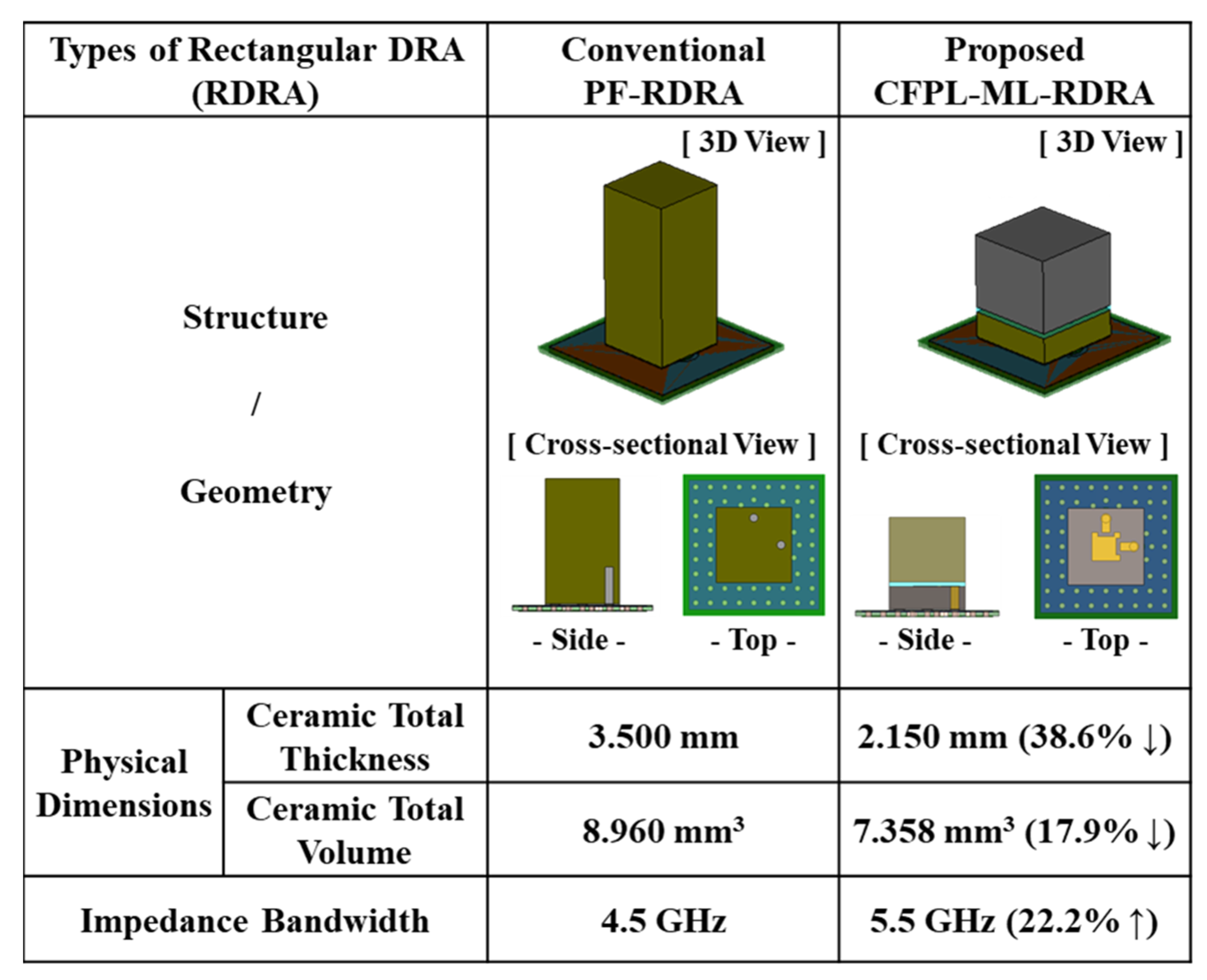
The proposed CFPL-ML-RDRA exhibits a broad −10 dB impedance bandwidth of 5.5 GHz, whereas the conventional PF-RDRA achieves a narrower −10 dB impedance bandwidth of 4.5 GHz, which is insufficient to cover the n257, n258, and n261 bands. Additionally, it is evident that the proposed CFPL-ML-RDRA demonstrates a broader 4 dBi realized gain (RG) bandwidth of 5.4 GHz compared to the PF-RDRA. Furthermore, the proposed CFPL-ML-RDRA has a height of 2.15 mm (excluding PCB thickness), which is 38.6% shorter than the height of the conventional PF-RDRA (total ceramic thickness of 3.5 mm), as summarized in Figure 3. Based on the comparative analysis of antenna performance and physical dimensions, it can be concluded that integrating a capacitive-fed patch structure into a multi-layered RDRA effectively broadens the impedance and gain bandwidth while reducing the antenna height.

2.2. Analysis of RDRA Resonant Modes

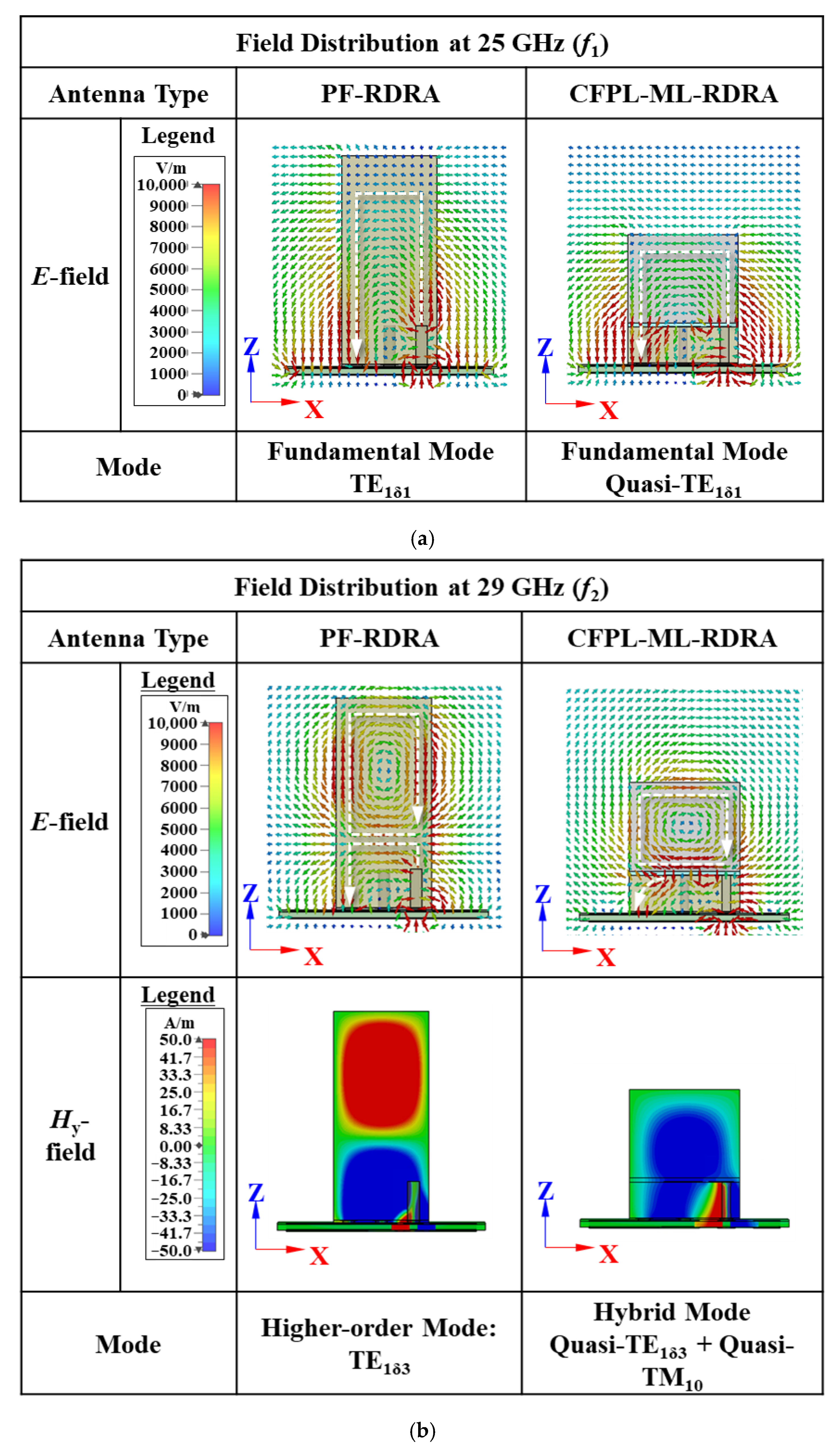
A field analysis within the rectangular dielectric resonator antennas (RDRAs) was conducted to elucidate the origin of the broad impedance and gain bandwidth while simultaneously reducing the antenna height through the integration of a capacitive-fed patch structure, as illustrated in Figure 4. In this analysis, Port 2 (H-pol.) was terminated with a 50 Ω load, while Port 1 (V-pol.) was excited. As depicted in Figure 2a, two distinct resonant modes within the frequency bands of interest are clearly observed for both RDRAs. By examining the simulated vector electric field (E-field) distributions of both RDRAs at 25 GHz, shown in Figure 4a, it is evident that the first resonance for both antennas is attributed to the fundamental resonant mode of the RDRA ( T E 1 δ 3 y ). However, as illustrated in Figure 4b, the origin of the second resonance differs between the conventional PF-RDRA and the proposed CFPL-ML-RDRA. The vector E-field and y-directed magnetic field (Hy-field) distributions of the PF-RDRA indicate that the second resonance is caused by a typical higher-order resonant mode of the RDRA ( T E 1 δ 3 y ). In contrast, the vector E-field and Hy-field distributions within the bottom ceramic substrate of the CFPL-ML-RDRA resemble those of the fundamental mode of a conventional patch antenna ( T M 10 ), which differs from those of the PF-RDRA. Additionally, the vector E-field and Hy-field distributions within the top ceramic substrate of the CFPL-ML-RDRA are similar to the T E 1 δ 3 y mode of the conventional PF-RDRA. Consequently, loading a capacitive-fed patch structure into a multi-layered RDRA generates a hybrid mode, combining T E 1 δ 3 y and T M 10 modes, which effectively broadens the impedance and gain bandwidth while reducing the antenna height. It is also noteworthy that the fields near the feeding probes are perturbed and counteracted due to the presence of metallic vias [10,21,22].

2.3. Parametric Studies on CFPL-ML-RDRA

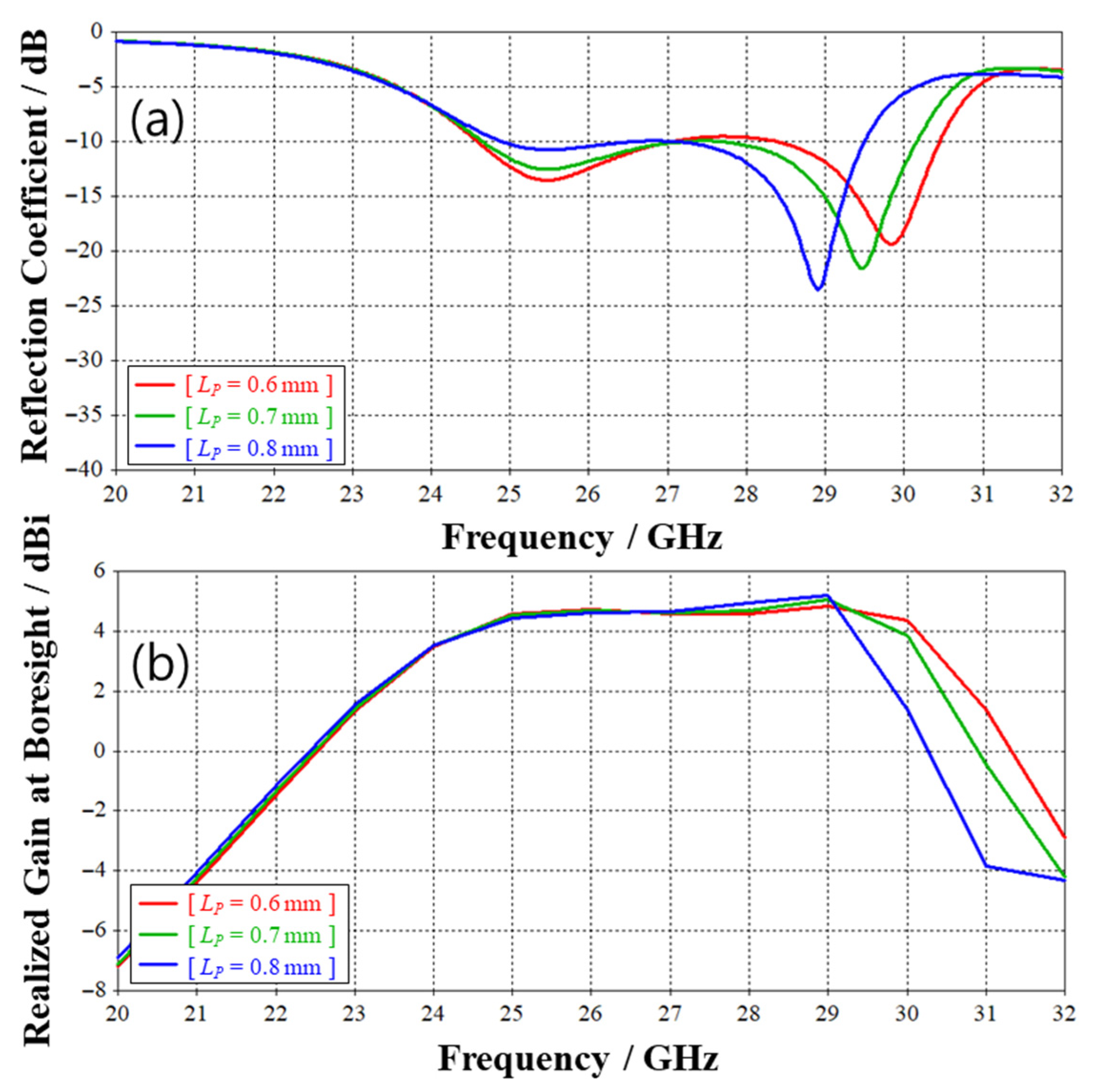
To further investigate the impact of the capacitive-fed patch on antenna performance, parametric studies were conducted on the patch length (LP), the height of the top ceramic substrate (HDT), and the length (LSV) and width (WSV) of the capacitive feeding strip. Figure 5a illustrates the frequency-dependent reflection coefficients for varying LP values, with all other parameters maintained at their nominal values. As LP increases from 0.6 mm to 0.8 mm, the second resonant frequency (f2) shifts from 29.8 GHz to 28.9 GHz. Additionally, the frequency at which the realized gain at boresight (θ, ϕ = 0°, 0°: RG00) crosses 4 dBi shifts to a lower frequency with increasing LP. However, the first resonant frequency (f1) and RG00 at lower frequencies remain largely unchanged. These results indicate that LP primarily influences the antenna performance near the second resonant mode. These parametric studies corroborate the simulated field distribution results presented in Figure 4.
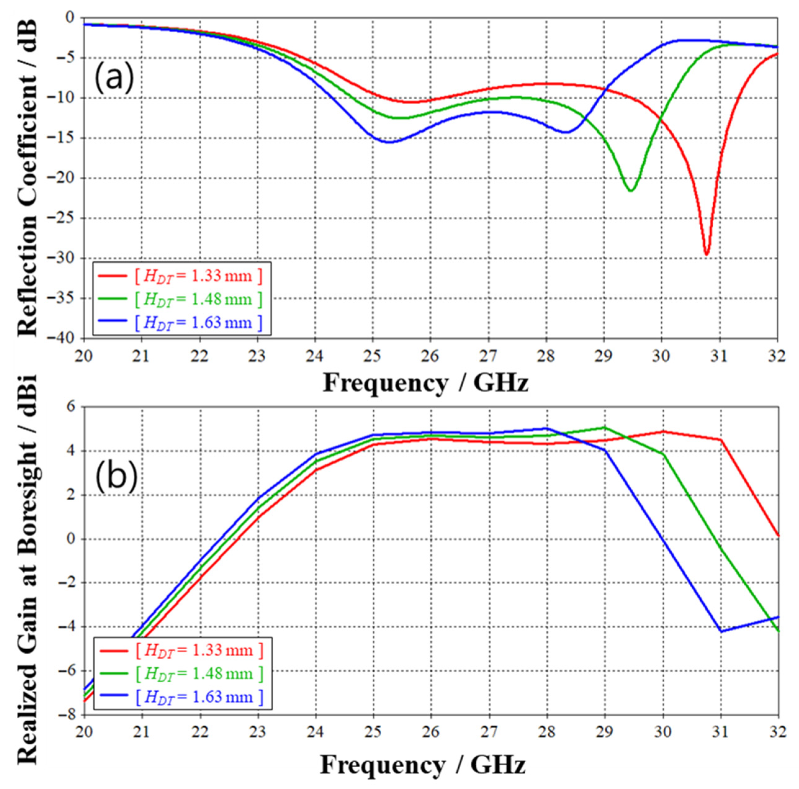
The effects of HDT on antenna performance are depicted in Figure 6a. As HDT increases from 1.33 mm to 1.63 mm, f2 shifts from 30.8 GHz to 28.3 GHz. Unlike the effect of LP, f1 also exhibits a slight decrease with increasing HDT. Furthermore, the frequency-dependent RG00 demonstrates similar phenomena, as shown in Figure 6b. This behavior can be attributed to the fact that f1 of the CFPL-ML-RDRA is influenced by altering the height of the dielectric resonator (HD) in the range of 2.0 mm to 2.3 mm with a step size of 0.15 mm, which results from changes in HDT. It is well-known that f1 can be estimated using the following equation:
f 1 = c 0 2 π ε r k x 2 + k y 2 + k z 2 ,
where
k y = π W D ,   k z = π 2 H D ,   L D = 2 k x tanh ( k x 0 k x ) ,   k x 0 = k y 2 + k z 2
and c0 is the speed of light [8,23]. Therefore, f1 slightly decreases as HDT increases.
Figure 7a,b show the effects of the capacitive feeding strip dimensions, LSV and WSV, respectively, on the frequency-dependent reflection coefficients. As shown in Figure 7a, increasing LSV from 0.2 mm to 0.4 mm results in an increase in f1 from 25 GHz to 26.4 GHz, while f2 remains nearly unchanged. Similarly, varying WSV exhibits a comparable trend in antenna performance, though its impact is less pronounced than that of LSV. This behavior can be attributed to the fact that the input impedance of the RDRA is influenced by changes in the length and width of the feeding probe [7,24]. Furthermore, optimizing LSV and WSV allows for improved impedance matching of the CFPL-ML-RDRA at frequencies between f1 and f2.
Based on these parametric studies, it is evident that optimizing these parameters can individually or concurrently control the two resonant modes, T E 1 δ 1 y and the hybrid mode, thereby enhancing the design flexibility of the antenna. This increased degree of freedom is a direct result of integrating the capacitive-fed patch structure into the multi-layered RDRA.

3. Antenna Fabrication and Measured Results

The proof-of-concept (PoC) antenna was fabricated and characterized to verify its performance. The fabricated PoC sample is shown in Figure 8. It is noteworthy that the manufacturing process of the CFPL-ML-RDRA is significantly simpler and more cost-effective compared to the conventional single-unit manufacturing process [7]. This advantage arises from the use of a multi-layered ceramic substrate with an adhesive polymer layer and via structure, which facilitates a batch process, making it more suitable for mass production. The volume of the fabricated CFPL-ML-RDRA measures 1.85 × 1.85 × 2.15 mm3 (0.15 λL × 0.15 λL × 0.17 λL, where λL is the free-space wavelength at 24 GHz). The ceramic substrate, with a relative permittivity (εr) of 21.5 and a loss tangent (tan δε) of 0.004, was utilized for fabrication.
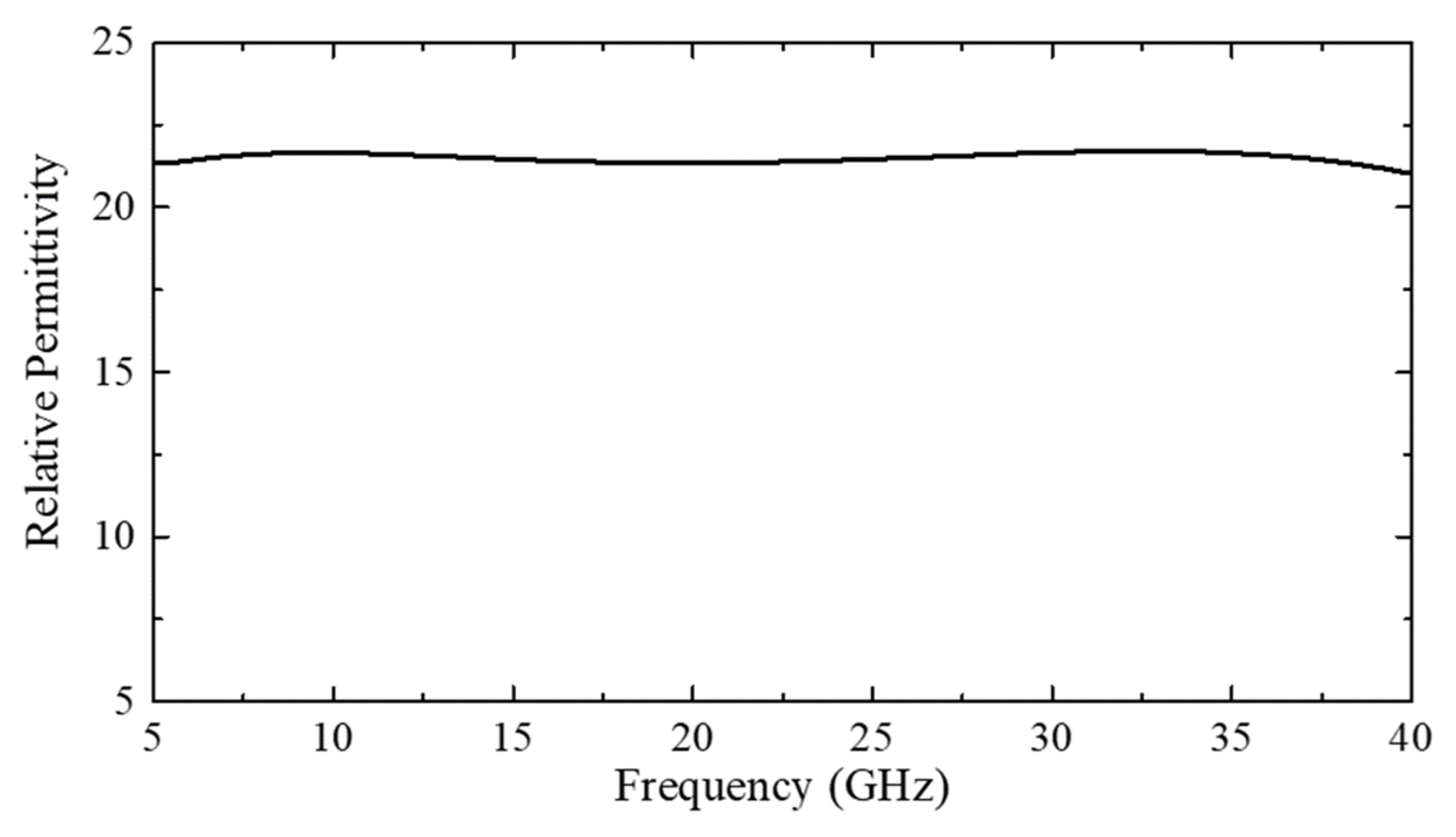
The εr of the ceramic substrate was measured to be 21.5 at 28 GHz using a vector network analyzer (VNA) and a measurement fixture employing the open-ended coaxial-probe method, as illustrated in Figure 9. The fabricated CFPL-ML-RDRA component was soldered onto a six-layer test PCB with a ground plane measuring 3.2 × 3.2 mm2. The test PCB has an εr of 3.57 and a tan δε of 0.004 across the operating frequency bands. An underfill process was performed to enhance the adhesion between the CFPL-ML-RDRA and the test PCB. The fabricated PoC sample was characterized using a VNA, GSG RF probe-tip, and a custom-designed gain measurement system. A standard gain comparison method using a calibrated horn antenna and an anechoic chamber was employed to characterize the antenna gain. The measurement setup included a GSG RF probe station and VNA to capture the boresight realized gain. The simulated total radiation efficiency of the proposed antenna exceeds 85% over the operating band (24–30 GHz), demonstrating high-efficiency performance due to low-loss ceramic materials and optimized feeding. Direct measurement of radiation efficiency was not feasible due to equipment limitations.
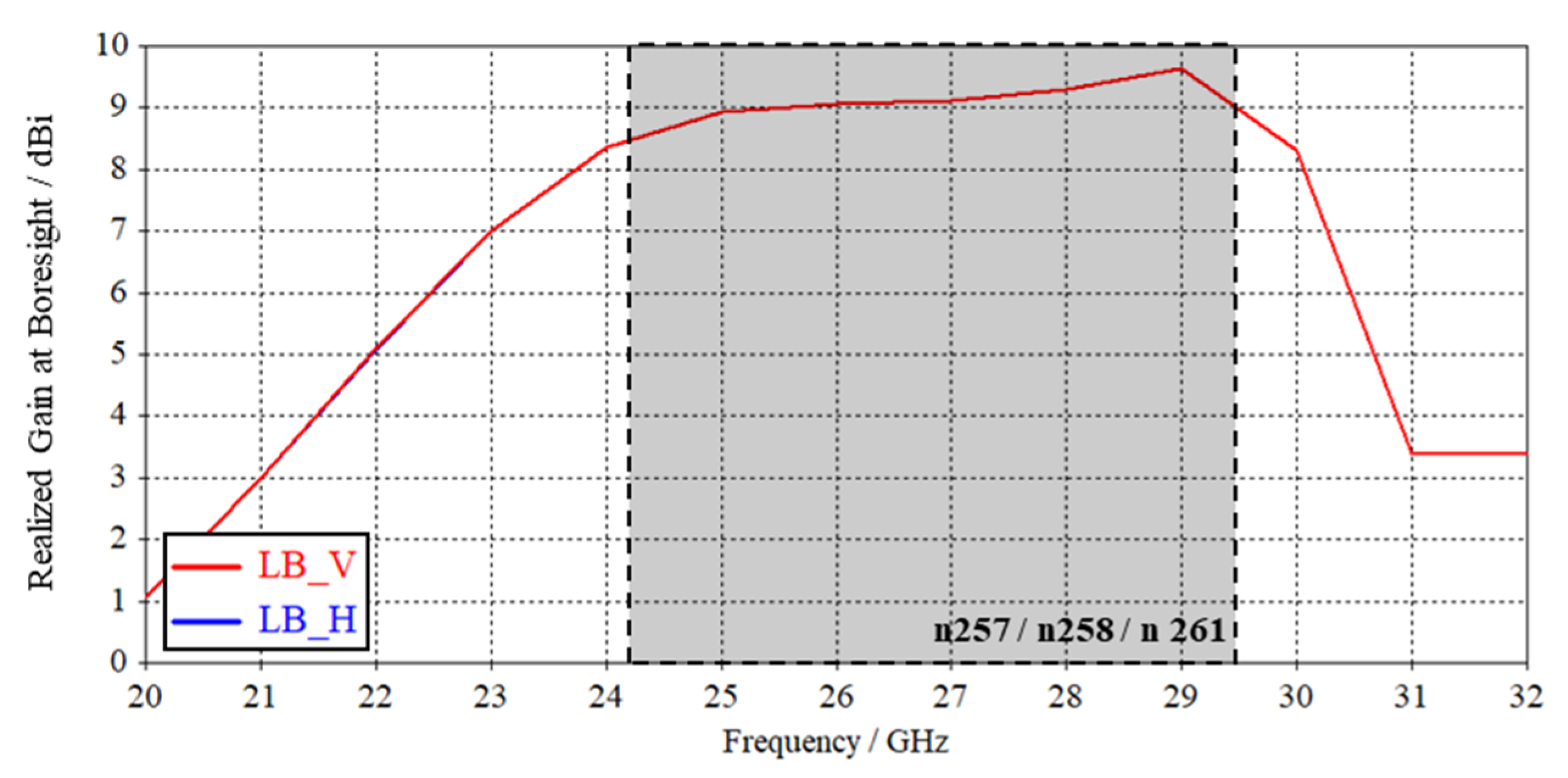
Figure 10a presents the measured and simulated frequency-dependent reflection coefficients, as well as the isolation between V- and H-polarizations of the CFPL-ML-RDRA. The experimental results demonstrate excellent reflection coefficients and isolation exceeding 15 dB across the frequency bands of interest. Additionally, Figure 10b displays the measured and simulated realized gain at boresight (RG00) for the single antenna. The measured data reveals a moderate and stable antenna gain exceeding 4 dBi within the n257, n258, and n261 bands.
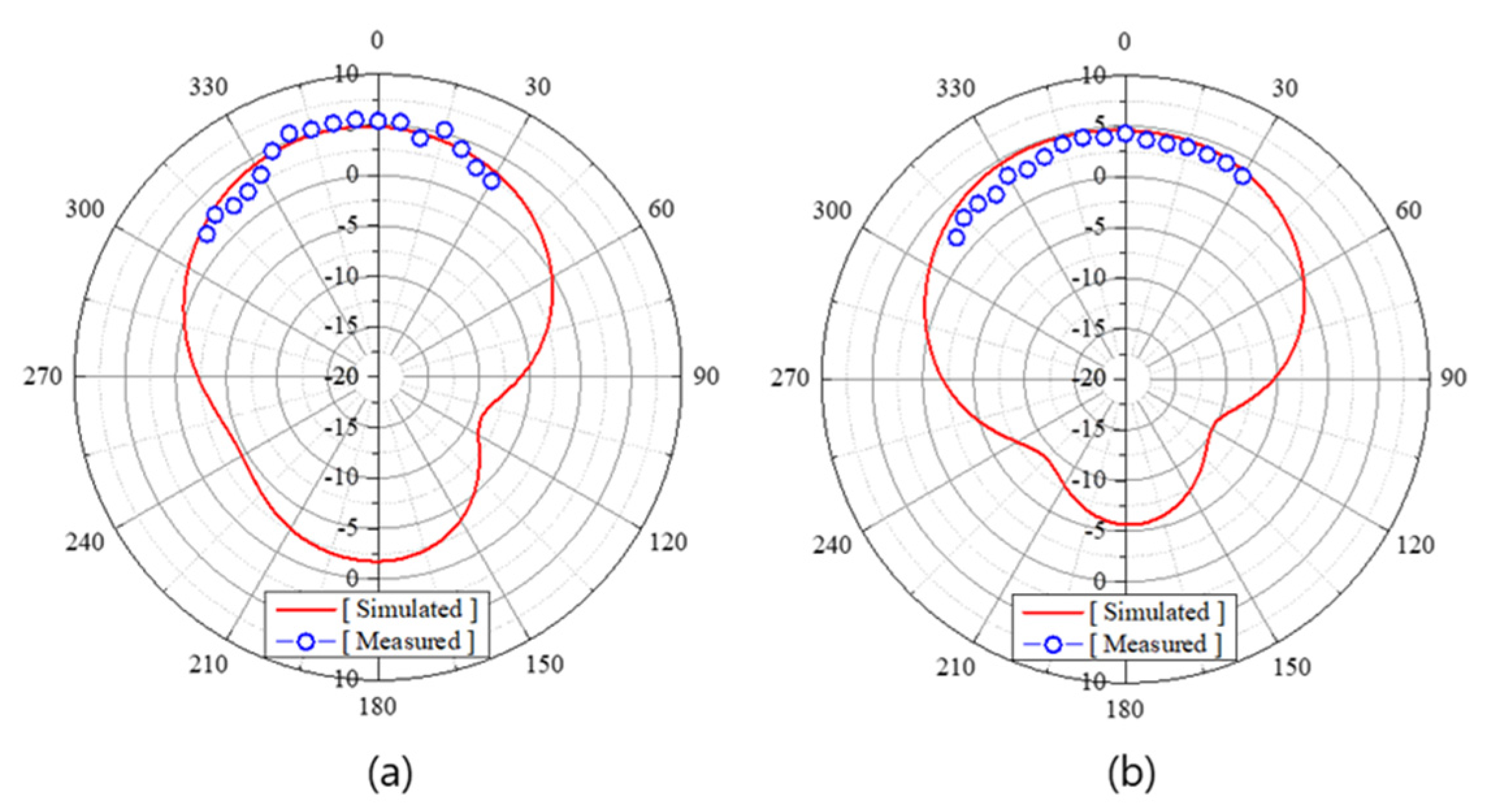
The measured and simulated E-plane radiation patterns of the antenna at 25 GHz and 29 GHz are depicted in Figure 11. Broadside radiation patterns are observed at both frequencies. It is noteworthy that the simulated and measured results, including frequency-dependent reflection coefficients, isolation between the two ports (V- and H-polarizations), peak realized gain, and E-plane radiation patterns, exhibit good agreement.

4. 1 × 4 Antenna Array Performance Simulation

As discussed in the Introduction, to compensate for the high propagation loss at mmWave frequencies, the antenna must be arranged in an array configuration to enhance its gain. Consequently, a uniform linear array comprising four proposed CFPL-ML-RDRA units was designed and simulated. Figure 12a illustrates the geometry of the 1 × 4 dual-polarized CFPL-ML-RDRA array. To achieve similar antenna performance for both polarizations while maintaining structural and electrical symmetry, the CFPL-ML-RDRA units are inclined at a 45° angle. The units are equally spaced at a distance of 5 mm and mounted on a test PCB with a ground plane measuring 20 × 3.2 mm2.
Figure 13 depicts the frequency-dependent realized gain at boresight (RG00). The array achieves a relatively high gain exceeding 8 dBi across the frequency bands of interest, even on the limited ground plane size.
To further evaluate the far-field characteristics, the 2D far-field radiation patterns of the antenna array at 25 GHz, 27 GHz, and 29 GHz in the ϕ = +45° plane (refer to the coordinate system in Figure 12b) are summarized in Figure 14. This plane corresponds to the E- and H-planes for V- and H-polarizations, respectively. Broadside radiation patterns are observed at all frequencies. For V- and H-polarizations in the same observation plane, the co-polarization components are Gθ and Gϕ, which are orthogonal to each other. Consequently, the array supports dual-polarization characteristics [25,26]. The cross-polarization discriminations (XPDs) for both polarizations in the boresight direction exceed 19 dB across the entire frequency bands of interest, which is considered excellent. Additionally, the far-field performance for V- and H-polarizations is nearly identical due to the array’s symmetry, which is advantageous for polarization diversity.
Given the limited space available in current smartphones, the size of the mmWave antenna array module is a critical factor. To miniaturize the antenna array module, the ground plane size must be reduced. Therefore, the effect of ground plane width (GND_W) on the RG00 of the antenna array was investigated. As shown in Figure 15, RG00 decreases by approximately 0.5 dB at 24.25 GHz when GND_W is reduced from 3.2 mm to 2.7 mm. The minimum RG00 for an array with GND_W of 2.7 mm remains above 8 dBi within the frequency bands of interest, which is still a reasonable gain for 5G mobile applications. Based on this parametric study, it can be concluded that the proposed antenna is less sensitive to ground plane size compared to conventional metal resonator-type antennas, such as microstrip patch antennas commonly used in 5G mmWave applications. Previous studies have shown that patch antenna performance, particularly in terms of gain and impedance bandwidth, is significantly influenced by ground plane size, especially when it is less than 1.0 λeff (effective wavelength in the medium) [27,28]. It is noteworthy that GND_W was the only parameter varied in this study. Consequently, further optimization of the antenna array could improve RG00 at lower frequency bands, as impedance matching degrades with decreasing GND_W [29,30,31,32].

5. Conclusions

In this paper, a wideband dual-polarized capacitive-fed patch-loaded multi-layer rectangular dielectric resonator antenna (CFPL-ML-RDRA) with a reduced antenna height has been proposed. The unit antenna was designed, simulated, fabricated, and characterized. The experimental results confirm the antenna’s excellent impedance and radiation characteristics. Furthermore, the measured results align well with the simulated results, demonstrating that the proposed structure is effective in broadening impedance and gain bandwidth while minimizing the antenna height. Additionally, antenna performance simulations indicate that an array utilizing the proposed antenna as an element maintains excellent far-field radiation performance even on a small ground plane. Overall, it can be concluded that the proposed antenna is a highly suitable candidate for fifth-generation (5G) millimeter-wave mobile applications.
The key contributions of this study include the development of a novel capacitive-fed patch-loaded multi-layered RDRA that excites a hybrid resonant mode, enabling significant bandwidth enhancement while achieving a low-profile structure. This configuration supports dual polarization, efficient performance, and compact integration, making it well-suited for next-generation 5G mmWave mobile platforms. Additionally, the proposed antenna demonstrates robustness to ground plane size reduction and scalability to array configurations.

Author Contributions

S.Y.A. wrote the main manuscript text and conducted the experiments related to the ceramic antenna concept. B.K. reviewed the manuscript and provided overall direction for the experiments. All authors have read and agreed to the published version of the manuscript.

Funding

This research received no external funding.

Institutional Review Board Statement

Not applicable.

Data Availability Statement

Data are contained within the article.

Acknowledgments

The authors express gratitude to Won Chul Lee from Samsung Electronics in South Korea for their valuable assistance with the discussions on dielectric resonator antennas.

Conflicts of Interest

Author Sung-Yong An and Boumseock Kim were employed by the company Samsung Electro-Mechanics Co., Ltd. The authors declare that the research was conducted in the absence of any commercial or financial relationships that could be construed as a potential conflict of interest.

References

  1. Saeidi, T.; Saleh, S.; Timmons, N.; McDaid, C.; Al-Gburi, A.J.A.; Razzaz, F.; Karamzadeh, S. High-gain miniaturized multi-band MIMO SSPP LWA for vehicular communications. Technologies 2025, 13, 66. [Google Scholar] [CrossRef]
  2. Lee, W.; Won, H.; Hong, Y.K.; Choi, M.; An, S.Y. Wideband patch antenna with modifield L-probe feeding for mmWave 5G mobile applications. Electronics 2024, 13, 3119. [Google Scholar] [CrossRef]
  3. An, S.Y.; Kim, B. Smallest form-factor multi-stacked ceramic patch antenna on package for 5G millimeter-wave mobile applications. Photonics Nanostruct.-Fundam. Appl. 2023, 57, 101189. [Google Scholar] [CrossRef]
  4. Hong, W.; Jiang, Z.H.; Yu, C.; Zhou, J.; Chen, P.; Yu, Z.; Yang, B.; Pang, X.; Jiang, M.; Cheng, Y.; et al. Multibeam antenna technologies for 5G wireless communications. IEEE Trans. Antennas Propag. 2017, 65, 6231–6249. [Google Scholar] [CrossRef]
  5. Liu, D.; Gu, X.; Baks, C.W.; Valdes-Garcia, A. Antenna-in-package design considerations for Ka-band 5G communication applications. IEEE Trans. Antennas Propag. 2017, 65, 6372–6379. [Google Scholar] [CrossRef]
  6. Lin, X. 3GPP evolution from 5G to 6G: A 10-year retrospective. Telecom 2025, 6, 32. [Google Scholar] [CrossRef]
  7. Keyrouz, S.; Caratelli, D. Dielectric resonator antennas: Basic concepts, design guidelines, and recent developments at millimeter-wave frequencies. Int. J. Antennas Propag. 2016, 2016, 6075680. [Google Scholar] [CrossRef]
  8. Mishra, P.K.; Jahagirdar, D.R.; Kumar, G. A review of broadband dual linearly polarized microstrip antenna design with high isolation. IEEE Antennas Propag. Mag. 2014, 56, 238–251. [Google Scholar] [CrossRef]
  9. Petosa, A.; Ittipiboon, A. Dielectric resonator antennas: A historical review and the current state of the art. IEEE Antennas Propag. Mag. 2010, 52, 91–116. [Google Scholar] [CrossRef]
  10. Pan, Y.M.; Yu, X.Q.; Zheng, S.Y. A simple decoupling method for 5G millimeter-wave MIMO dielectric resonator antennas. IEEE Trans. Antennas Propag. 2019, 67, 2224–2234. [Google Scholar] [CrossRef]
  11. Petosa, A.; Thirakoune, S. Rectangular dielectric resonator antennas with enhanced gain. IEEE Trans. Antennas Propag. 2011, 59, 1385–1389. [Google Scholar] [CrossRef]
  12. Chair, R.; Kishk, A.A.; Lee, K.F. Experimental investigation for wideband perforated dielectric resonator antenna. Electron. Lett. 2006, 42, 137–139. [Google Scholar] [CrossRef]
  13. Fang, X.S.; Shi, K.P.; Sun, Y.X. Design of the single-/dual-port wideband differential dielectric resonator antenna using higher order mode. IEEE Antennas Wirel. Propag. Lett. 2020, 19, 1605–1609. [Google Scholar] [CrossRef]
  14. Gupta, R.D.; Parihar, M.S. Differentially fed wideband rectangular DRA with high gain using short horn. IEEE Antennas Wirel. Propag. Lett. 2017, 16, 1804–1807. [Google Scholar] [CrossRef]
  15. Perron, A.; Denidni, T.A.; Sebak, A.-R. High-gain hybrid dielectric resonator antenna for millimeter-wave applications: Design and implementation. IEEE Trans. Antennas Propag. 2009, 57, 2882–2892. [Google Scholar] [CrossRef]
  16. Guha, D.; Antar, Y.M.M.; Ittipiboon, A.; Petosa, A.; Lee, D. Improved design guidelines for the ultra wideband monopole-dielectric resonator antenna. IEEE Antennas Wirel. Propag. Lett. 2006, 5, 373–376. [Google Scholar] [CrossRef]
  17. Guha, D.; Gupta, B.; Antar, Y.M.M. Hybrid monopole-DRAs using hemispherical/conical-shaped dielectric resonators: Improved ultrawideband designs. IEEE Trans. Antennas Propag. 2012, 60, 393–398. [Google Scholar] [CrossRef]
  18. Gao, Y.; Popov, A.P.; Ooi, B.L.; Leong, M.S. Experimental study of wideband hybrid dielectric resonator antenna on small ground plane. Electron. Lett. 2006, 42, 731–733. [Google Scholar] [CrossRef]
  19. Lin, Y.-F.; Chen, H.-M.; Lin, C.-H. Compact dual-band hybrid dielectric resonator antenna with radiating slot. IEEE Antennas Wirel. Propag. Lett. 2009, 8, 6–9. [Google Scholar]
  20. Hong, W.; Baek, K.H.; Ko, S. Millimeter-wave 5G antennas for smartphones: Overview and experimental demonstration. IEEE Trans. Antennas Propag. 2017, 65, 6250–6261. [Google Scholar] [CrossRef]
  21. Guha, D.; Gajera, H.; Kumar, C. Cross-polarized radiation in a cylindrical dielectric resonator antenna: Identification of source, experimental proof, and its suppression. IEEE Trans. Antennas Propag. 2015, 63, 1863–1867. [Google Scholar] [CrossRef]
  22. Guha, D.; Gajera, H.; Kumar, C. Perturbation technique to improve purity of modal fields in dielectric resonator antenna resulting in reduced cross-polarized radiation. IEEE Trans. Antennas Propag. 2015, 63, 3253–3257. [Google Scholar] [CrossRef]
  23. Mongia, R.K.; Ittibipoon, A.; Cuhaci, M. Low profile dielectric resonator antennas using a very high permittivity material. Electron. Lett. 1994, 30, 1362–1363. [Google Scholar] [CrossRef]
  24. Li, B.; Leung, K.W. Strip-fed rectangular dielectric resonator antennas with/without a parasitic patch. IEEE Trans. Antennas Propag. 2005, 53, 2200–2207. [Google Scholar]
  25. Li, Y.; Zhang, Z.; Chen, W.; Feng, Z.; Iskander, M.F. A dual-polarization slot antenna using a compact CPW feeding structure. IEEE Antennas Wirel. Propag. Lett. 2010, 9, 191–194. [Google Scholar] [CrossRef]
  26. Lee, W.; Hong, Y.-K.; Lee, J.; Gillespie, D.; Ricks, K.G.; Hu, F.; Abu-Qahouq, J. Dual-polarized hexaferrite antenna for unmanned aerial vehicle (UAV) applications. IEEE Antennas Wirel. Propag. Lett. 2013, 12, 765–768. [Google Scholar] [CrossRef]
  27. Lier, E.; Jakobsen, K.R. Rectangular microstrip patch antennas with infinite and finite ground plane dimensions. IEEE Trans. Antennas Propag. 1983, 31, 978–984. [Google Scholar] [CrossRef]
  28. Nguyen, M.T.; Kim, B.; Choo, H.; Park, I. Effects of ground plane size on a square microstrip patch antenna designed on a low-permittivity substrate with an air gap. In Proceedings of the 2010 International Workshop on Antenna Technology (iWAT), Lisbon, Portugal, 1–3 March 2010; pp. 1–4. [Google Scholar]
  29. Rai, H.T.; Mu, G.W.; Lu, R.Q. Integrated Dielectric Resonator Antenna to Traditional Antenna for Better Bandwidth and Gain. Natl. J. Antennas Propag. 2024, 6, 9–16. [Google Scholar]
  30. Bizan, M.S.; Naseri, H.; Pourmohammadi, P.; Melouki, N.; Iqbal, A.; Denidni, T.A. Dual-Band Dielectric Resonator Antenna with Filtering Features for Microwave and Mm-Wave Applications. Micromachines 2023, 14, 1236. [Google Scholar] [CrossRef]
  31. Tirado-Méndez, J.A.; Jardón-Aguilar, H.; Linares-Miranda, R.; Flores-Leal, R.; Vasquez-Toledo, A.; Gomez-Villanueva, R.; Perez-Miguel, A. Compact Four-Port Axial Symmetry UWB MIMO Antenna Array with Bandwidth Enhancement Using Reactive Stub Loading. Symmetry 2025, 17, 1285. [Google Scholar] [CrossRef]
  32. Cepeda, L.E.; Garza, L.A.; Panduro, M.A.; Reyna, A.; Zuñiga, M.A. Thinned Eisenstein Fractal Antenna Array Using Multi-Objective Optimization for Wideband Performance. Appl. Sci. 2025, 15, 5584. [Google Scholar] [CrossRef]
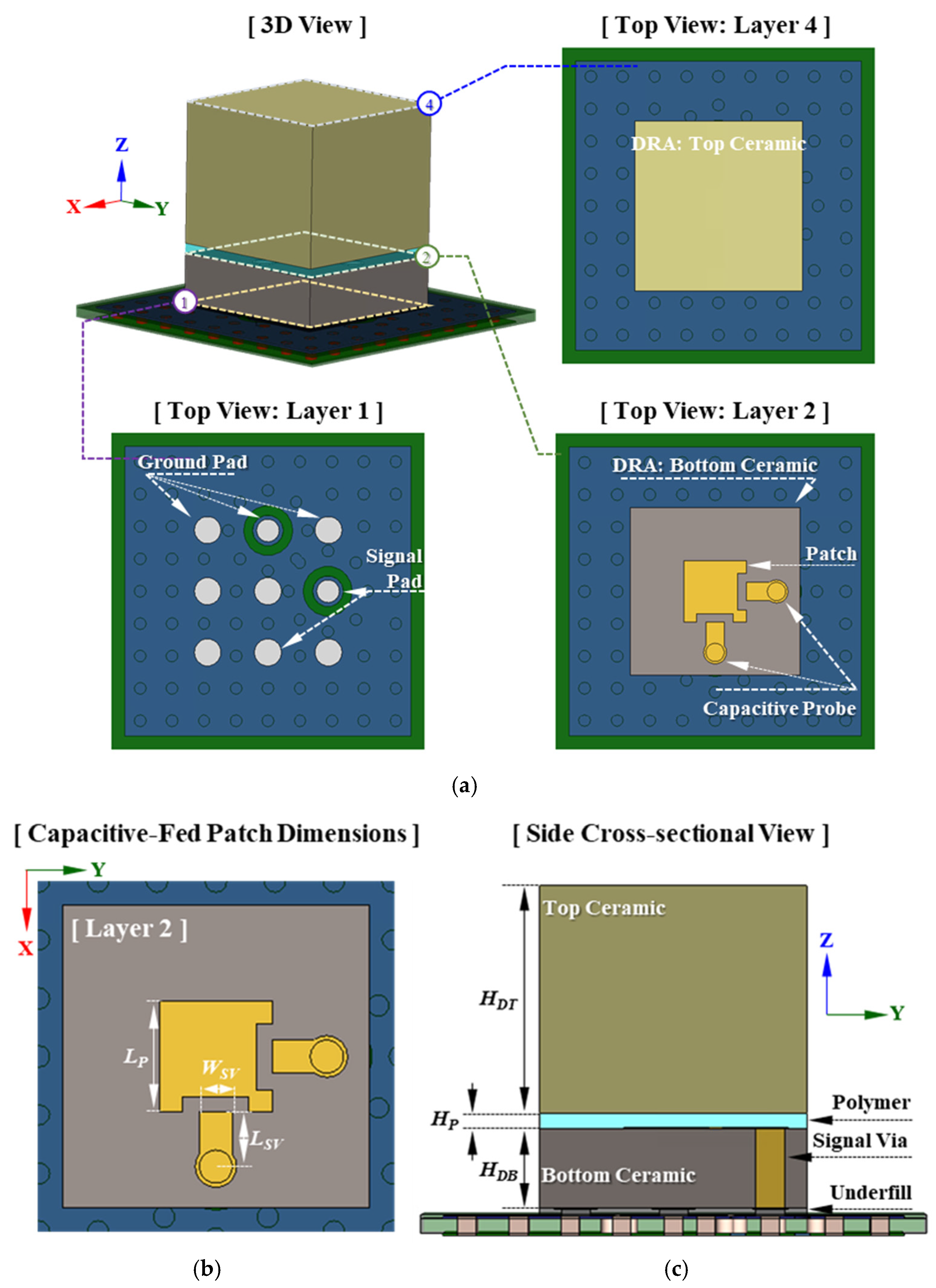
Figure 1. Geometry and dimensions of the proposed capacitive-fed patch loaded multi-layered rectangular dielectric resonator antenna (FAR > L-ML-RDRA): (a) 3D and top views, (b) detailed top view of the capacitive-fed patch with critical parameters, and (c) side cross-sectional view of the layered antenna structure.
Electronics 14 03756 g001
Figure 2. Simulated unit antenna performance of two different rectangular dielectric resonator antennas: frequency-dependent (a) reflection coefficients and (b) realized gain at boresight.
Electronics 14 03756 g002
Figure 3. Comparison of the height and performance characteristics between the conventional probe-fed RDRA (PF-RDRA) and the proposed capacitive-fed patch-loaded multi-layered RDRA (CFPL-ML-RDRA), highlighting the reduction in antenna height and enhancement in gain bandwidth.
Electronics 14 03756 g003
Figure 4. Simulated cross-sectional field distributions of the conventional probe-fed RDRA (left) and the proposed capacitive-fed patch-loaded multi-layered RDRA (right) at (a) 25 GHz and (b) 29 GHz. The color scale represents the electric field intensity, while arrows indicate the magnetic field distribution.
Electronics 14 03756 g004
Figure 5. Parametric study of the proposed capacitive-fed patch-loaded multi-layered dielectric resonator antenna (CFPL-ML-RDRA) with different patch lengths (LP): (a) simulated frequency-dependent reflection coefficients, and (b) simulated realized gain at boresight (RG00).
Electronics 14 03756 g005
Figure 6. Simulated frequency dependent (a) reflection coefficient and (b) realized gain at boresight of the proposed capacitive-fed patch loaded multi-layered dielectric resonator antenna with different height of the top ceramic substrate (HDT).
Electronics 14 03756 g006
Figure 7. Simulated frequency dependent reflection coefficient of the proposed capacitive-fed patch loaded multi-layered dielectric resonator antenna with different (a) probe strip length (LSV) and (b) probe strip width (WSV).
Electronics 14 03756 g007
Figure 8. Photo-images of the fabricated antenna: (a) right isometric 3D view and (b) lower right rear isometric 3D view of the capacitive-fed patch loaded multi-layered rectangular dielectric resonator antenna (CFPL-ML-RDRA) and (c) 3D view of the CFPL-ML-RDRA mounted on the test PCB.
Electronics 14 03756 g008
Figure 9. The frequency-dependent relative permittivity of the ceramic substrate.
Electronics 14 03756 g009
Figure 10. Measured and simulated frequency-dependent (a) reflection coefficient and (b) realized gain at boresight of the proposed capacitive-fed patch loaded multi-layered dielectric resonator antenna.
Electronics 14 03756 g010
Figure 11. Simulated and measured radiation patterns of the proposed capacitive-fed patch loaded multi-layered dielectric resonator antenna at (a) 25 GHz and (b) 29 GHz.
Electronics 14 03756 g011
Figure 12. Geometry and port configuration of the 1 × 4 dual-polarized capacitive-fed patch loaded rectangular dielectric resonator antenna array: (a) 3D view and (b) top view.
Electronics 14 03756 g012
Figure 13. Simulated frequency-dependent realized gain at boresight with 3D far-field radiation patterns at 27 GHz (inset) for both polarization of the 1 × 4 dual-polarized capacitive-fed patch loaded rectangular dielectric resonator antenna array.
Electronics 14 03756 g013
Figure 14. Simulated 2D far-field radiation patterns of 1 × 4 dual-polarized capacitive-fed patch loaded rectangular dielectric resonator antenna array at 25 GHz, 27 GHz, and 29 GHz.
Electronics 14 03756 g014
Figure 15. Simulated frequency-dependent realized gain at boresight of 1 × 4 dual-polarized capacitive-fed patch loaded rectangular dielectric resonator antenna array with different ground plane width.
Electronics 14 03756 g015
Disclaimer/Publisher’s Note: The statements, opinions and data contained in all publications are solely those of the individual author(s) and contributor(s) and not of MDPI and/or the editor(s). MDPI and/or the editor(s) disclaim responsibility for any injury to people or property resulting from any ideas, methods, instructions or products referred to in the content.