Abstract
A new method of round-trip spiral cruising orbit design for GEO object surveillance is proposed using relative orbit elements (ROEs). The relationship between the in-plane configuration of spiral cruising orbits and ROEs is described. After that, in-plane impulse control strategies are shown for round-trip spiral cruising orbits, based on the relative motion control laws. Along-track maneuvers are performed on both sides of the cruise region in the strategies. Finally, the impulse control strategies are simulated, and the required velocity increment and performance of the cruising orbit are analyzed. The results indicate that the proposed configuration and control strategies are effective for round-trip spiral cruising orbit design. The required velocity impulse increases with cruising velocity while being free from the cruising period. Only a few velocity increments are needed for closely observing objects in the cruise region multiple times.
1. Introduction
The geosynchronous Earth orbit (GEO) is a highly valuable orbital resource. With the increasing number of GEO resident objects, the orbital environment for GEO spacecraft is becoming increasingly complex. Monitoring and identifying GEO targets on-orbit is of great significance for enhancing collision warning capability, ensuring spacecraft operational safety, and improving space situational awareness. There exists a series of methods for monitoring GEO targets. For example, GEO targets can be observed through ground-based optical telescopes [1]. However, the altitude of GEO above Earth is nearly 36,000 km, making it difficult to detect small targets. Thus, space-based observation methods have attracted much interest, such as the geostationary rendezvous [2], the collocation technique [3] (where the observer satellite operates very close to a target in the same geosynchronous slot), and the GEO monitoring constellation deployed in eccentric orbits around the GEO belt [4].
A spiral cruising orbit is a type of relative trajectory defined with respect to a designated target orbit or a specific arc segment of that orbit. A single spacecraft, referred to as the cruising spacecraft, can perform spiral cruising maneuvers near the target orbit to achieve close-range and high-precision observations of all resident objects and the space environment along the designated arc. By applying orbital maneuvers at the boundaries of the defined GEO arc segment, the cruising spacecraft can reverse its spiral direction, thus enabling repeated round-trip inspections of multiple space targets within a specific GEO arc.
Several studies have been conducted on spiral cruising orbit design and control. Using Clohessy–Wiltshire (C-W) equations [5], a widely used relative motion model that describes relative positions and velocity evolutions, Zhang, Y. et al. [6] proposed a set of descriptive parameters for spiral cruising orbits and developed methods for designing such orbits and controlling round-trip spiral maneuvers. Later, Zheng, L. et al. [7] applied a particle swarm optimization algorithm to study the fuel optimization problem for multi-target spiral cruising in GEO. Zhou H.J. et al. [8] derived GEO relative motion equations based on a linearized first-order approximation of classical orbital element differences. Xu Y.L. et al. [9] developed a description method for GEO spiral cruising orbits based on station-keeping orbital elements and analyzed long-term perturbation effects from Earth’s J2 and J22 terms. Recently, Chen, N. et al. [10] proposed an orbit design method for traverse inspection of GEO-belt targets. Moreover, a method for patrolling inclined geosynchronous orbit (IGSO) targets is presented based on crossing points and spiral rings [11].
Considering that the spiral cruising orbit can be regard as a type of spacecraft relative motion, another relative motion model, namely relative orbital elements (ROEs), have attracted widespread attention in recent years due to the clear geometric relationship for describing relative motion [12]. This provides an opportunity for designing the spiral cruising orbit conveniently. The concept of ROEs can be traced back to He, Q. [13], who established relative motion equations based on ROEs for near-circular reference orbits and proposed both in-plane and out-of-plane ROE control strategies. Subsequently, Han, C. [12] and Yin, J. [14] provided a strict definition of ROEs with clearer geometric interpretation, facilitating a configuration design of relative motion. Based on ROEs, Bai, S. et al. [15] proposed a fly-around formation design method using a parallelogram configuration, and multistage, constant-vector, thrust control strategies [16,17,18] were utilized for formation control. Recently, ROEs have been applied for exoatmospheric intercept guidance [19], bounded hovering formation control in elliptical orbits [20], and relative orbit transfer [18]. Although ROEs have been successfully used for satellite formation design and control, difficulties arise when they are utilized for spiral cruising orbit description and control. First, ROEs only describe general characteristics of relative motion; the intuitive geometric parameters for describing spiral cruising orbits still need to be determined. Next, the relationships between ROEs and the geometric parameters of spiral cruising orbits have not been studied. Finally, an efficient control method for these geometric parameters is still unclear.
The main objective of this paper is to develop a set of intuitive geometric parameters for GEO spiral cruising orbit design and an effective spiral cruising orbit control method. First, the in-plane descriptive parameters for spiral cruising orbits are presented, and the mapping relationship between these parameters and ROEs is derived. Next, based on the relative motion control equations for near-circular orbits, we propose three types of in-plane impulsive control strategies for the spiral cruising orbit: cruising speed control, combined control of cruising speed and radial cruising radius, and in-plane, full-parameter control.
This paper makes two main contributions. First, a new set of geometric parameters for describing GEO spiral cruising orbits is proposed. In previous works [6,7,8,9], the geometric interpretation of the relationship between the spiral cruising orbit and orbit states remains unclear and not intuitive, thus preventing a fast spiral cruising orbit design in engineering application. The proposed geometric parameters are intuitive, making it simple for the spiral cruising orbit design in engineering practice. Second, analytical impulsive control methods for the proposed geometric parameters are developed. In previous work [9], cruising orbit design relied on numerical optimizations, which are computationally expensive. In this paper, the proposed geometric parameters associate the spiral cruising motion with ROEs, and the analytical control strategy of the ROEs can be directly utilized for cruising orbit control; thus, they are efficient and suitable for on-board application in space missions.
The rest of the article is organized as follows: Section 2 describes the geometric parameters of the GEO spiral cruising orbit, as well as the relationships between these parameters and ROEs. Section 3 presents the control strategies for the geometric parameters of the round-trip spiral cruising orbit. In Section 4, the effectiveness of the proposed geometric parameters, as well as their control methods, are validated through numerical examples. Finally, the conclusions are summarized in Section 5.
2. Description Method of Spiral Cruising Orbits
The spiral cruising orbit essentially represents the relative trajectory of an observer spacecraft with respect to a reference spacecraft. To describe the geometric characteristics of the spiral cruising orbit more intuitively, this paper introduces a close-range relative motion model based on ROEs.
2.1. Definition of Relative Orbit Elements
To characterize the relative motion between two spacecrafts (denoted as the observer and reference satellites), reference [8] adopted a spherical geometry approach to strictly define the ROEs, namely the relative drift rate , the relative eccentricity vector , the relative inclination vector , and the initial relative mean latitude . Specifically, represents the difference in the mean motion of the observer and reference satellite. describes the orbital shape of the observer satellite with respect to the reference satellite, where is the eccentricity vector of the reference satellite’s orbit, and represents the projection of the eccentricity vector of the observer satellite’s orbit onto the orbital plane of the reference satellite. is expressed as the unit inclination vector of the observer satellite projected onto the orbital plane of the reference satellite. In addition, is the difference in the mean arguments of latitude between the two satellites and is used to measure their phase error. The detailed definition and explanations for ROEs are given by [12]. Under close-range conditions, the observer satellite’s ROEs with respect to the reference satellite is given by [12], as follows:
where and are the classical orbital elements of satellites, the observer satellite and the reference satellite, respectively. Here, , , , , , and denote the semi-major axis, eccentricity, inclination, right ascension of ascending node, argument of perigee, and mean anomaly, respectively. And the subscripts “obs” and “ref” represent the observation and reference satellites, respectively. In addition, and are the mean motion of the observer satellite and the reference satellite, respectively, where is the central-body gravitational constant.
2.2. Relative Motion Equations
Reference [13] provides the relative motion equations of an observer spacecraft in a near-circular reference orbit, expressed in the reference-centered orbital coordinate frame, as follows:
Here, denotes the argument of latitude of the reference satellite and denotes the position of the observer spacecraft in the orbital-centered coordinate frame of the reference spacecraft, where the , , and directions correspond to the along-track, cross-track, and radial directions, respectively; denotes the velocity of the observer spacecraft in the same frame; and represents the ROEs at time .
From Equations (2) and (3), it is evident that the along-track and radial component motion is decoupled from the cross-track direction. Since the X-Z plane is the orbital plane of the reference satellite, the in-plane and out-of-plane motions can be considered independently. This paper focuses on in-plane motion only.
2.3. Analysis of In-Plane Relative Motion Trajectories
We define the phase angle of the relative eccentricity vector as
The definition of function is as follows:
Accordingly, we have
where is the 2-norm of the relative eccentricity vector.
Substituting Equation (6) into Equations (2) and (3) yields
According to the first two formulas of Equation (7), the terms and can be expressed as
Accordingly, since , we have
From Equation (9), it can be seen that the in-plane relative trajectory is an ellipse whose center drifts along the along-track direction. At each moment, the observer satellite lies on a so-called instantaneous ellipse. When , the relative motion trajectory is shown in Figure 1, as follows:
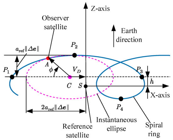
Figure 1.
Relative motion trajectory.
As shown in Figure 1, is the reference satellite, is the observer satellite, and is the instantaneous ellipse center; the semi-major and semi-minor axes of the instantaneous ellipse are and , respectively. The center of the ellipse drifts along-track with the speed of , and the coordinate of the center’s z-component is given by
Define as the in-plane phase angle of the observer satellite on the instantaneous ellipse as follows:
is defined as the vertex of the spiral ring, and it is the point on the instantaneous ellipse where the relative velocity direction is opposite to . Then, when the observer satellite arrives at the point , we have
Accordingly, substituting Equation (7) into Equation (12) yields
Denote the in-plane phase angle of point P as . It satisfies the following equation:
2.4. In-Plane Geometric Parameter of Spiral Cruising Orbit
The in-plane parameters used to describe the geometry of a spiral cruising orbit are illustrated in Figure 2.
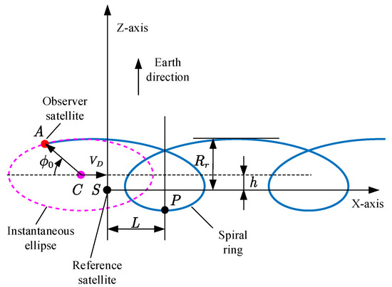
Figure 2.
Parameters within the spiral orbit plane.
As shown in Figure 2, these geometric parameters include the cruising velocity , the cruising radius , the location of the spiral vertex , and the initial in-plane phase angle . Here, denotes the along-track drift rate of the instantaneous ellipse center and represents the drift distance of the observer satellite in each orbit revolution; represents the maximum distance between the spiral trajectory and the reference orbit within the orbital plane; represents the along-track coordinate of the vertex of the spiral ring; and is the initial phase angle of the observer spacecraft in the instantaneous ellipse. Subsequently, the relationship between the geometric parameters and ROEs are derived as follows.
- Cruising Velocity
The along-track drift distance of the observer satellite with respect to the reference satellite in one orbit revolution is
The cruising angular velocity of the GEO spiral cruising orbit is
For GEO reference orbits, the relationship between the cruising velocity and parameters such as the relative drift rate is shown in Figure 3.
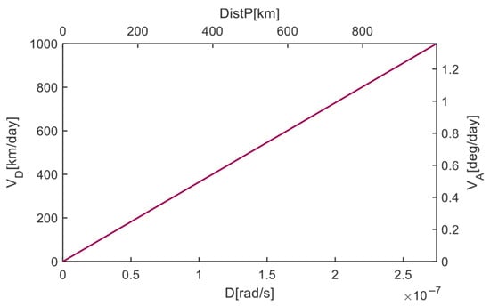
Figure 3.
The relationship between the relative drift rate and the cruising speed, cruising angular velocity, and the drift distance in each orbit revolution.
- 2.
- Cruising Radius
As shown in Figure 2, the cruising radius is given by
It is evident that when the spiral loop exists, , the radial cruising radius satisfies the condition .
- 3.
- Initial In-Plane Phase Angle
Let be the argument of latitude of the reference satellite at the initial time; the in-plane phase angle of the observer satellite is
where is given by Equation (4).
- 4.
- Spiral Vertex Location
Substituting the Equations (11) and (14) into Equation (7), the along-track coordinate of the spiral vertex is given by
where is the time when the observed satellite arrives at the vertex in the spiral ring, and the latitude argument of the reference satellite at this time is given by
For near-circular orbits, the following approximation holds:
Therefore, the along-track location of the spiral vertex is given by
Given the classical orbital elements of the reference satellite, and once the spiral cruising parameters are specified (cruising velocity , radial cruising radius , initial in-plane phase angle , and spiral vertex location ), the corresponding in-plane ROEs—, , and —can be determined by jointly solving the derived Equations (6), (15), (18), (20) and (23). Since the relative inclination vector is unrelated to in-plane motion, we may assign and . This yields a complete set of ROEs compatible with the desired spiral cruising geometry.
The absolute orbital elements of the spiral cruising spacecraft can then be calculated by applying the known transformation from ROEs to absolute elements.
3. Control Strategies for Round-Trip Spiral Cruising Orbits
A round-trip spiral cruising orbit refers to a type of relative trajectory that allows the observer spacecraft to perform repeated close-range inspections of multiple targets within a designated arc segment of a GEO [6]. This is achieved by applying in-plane impulsive maneuvers at the boundaries of the cruising region to adjust the geometric parameters of the spiral cruising orbit, thereby reversing the cruising direction.
In this section, the cruising region is defined in terms of the sub-satellite point longitudes in GEO. Virtual reference satellites are placed at the boundaries of the cruising region. The control of spiral cruising orbit geometric parameters is then transformed into the control of ROEs. Based on the impulsive control equations for relative motion in near-circular orbits derived in [13], control strategies under various constraint conditions are formulated and analyzed. These constraints include the following:
- Cruising velocity constraint;
- Combined constraint on cruising velocity and cruising radius;
- In-plane full-parameter control.
3.1. Reference Satellite Placement Strategy
A schematic diagram of the round-trip spiral cruising orbit is shown in Figure 4.
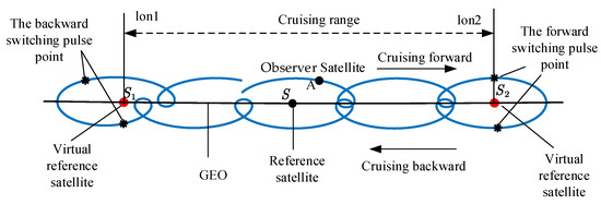
Figure 4.
Schematic diagram of the round-trip spiral cruising orbit.
As can be seen, the observer satellite A performs a round-trip spiral motion around the geostationary orbit. The relative trajectory of the observer satellite is defined with respect to the reference satellite S in GEO. Let and denote the longitudes of the cruising region boundary. Note that the reference satellite S is used solely for visualization of the spiral cruising orbit and does not influence the actual control of relative motion of the observer satellite. This is because the large along-track range of the round-trip cruising orbit may result in significant radial errors due to the nonlinearity of the relative motion, thus leading to significant errors in cruising orbit control. To address this problem, virtual reference satellites and are placed at GEO corresponding to the cruising region boundaries and , respectively. These virtual reference satellites serve as local reference points to ensure the linearity of the relative motion for control maneuvers.
When the observer satellite A cruises forward and arrives at the longitude , the virtual reference satellite is taken as the reference for cruising orbit control. The ROEs of the observer satellite with respect to are evaluated, and the cruising orbit geometric parameters of the reverse spiral cruising orbit are defined accordingly. Subsequently, tangential impulsive maneuvers are executed to transition the observer satellite A into the reverse cruising orbit so that it can cruise backward to the other boundary . And at the point , the virtual reference satellite is taken as the reference for cruising orbit control to ensure the observer satellite cruising forward to the boundary again. The control strategy of the cruising orbit at each boundary is described in detail in the following subsection.
3.2. In-Plane, Along-Track Impulsive Maneuver Equation
In-plane impulsive control can be categorized into along-track and radial direction impulsive controls. Along-track impulses are more efficient in eliminating deviations in the relative eccentricity vector and initial mean latitude offset, requiring less velocity increment than the radial impulses. Therefore, the control strategy in this paper adopts in-plane along-track impulsive maneuvers.
To derive the along-track impulse maneuver equation, assume that the along-track velocity impulse is given by (the radial velocity impulse ). Let , , and denote the ROEs of the observer satellite before the impulsive maneuver moment, and denote the relative position components, and and denote the relative velocity components before the maneuver moment. In addition, , , , and denote the ROEs after the maneuver moment, and , , , and denote the relative position and velocity components after the maneuver moment. From Equations (2) and (3), we have
Noting that the relative velocity can be changed instantaneously by the impulsive maneuver and the relative position is unchanged at the maneuver moment, we have
Accordingly, by substituting Equations (25) and (26) into Equation (27), the in-plane along-track impulsive control equations are as follows [9]:
Here, , , , and represent the changes in , , , and before and after the maneuver, respectively. Solving Equation (28) yields
It can be seen that a single along-track velocity impulse can only eliminate one deviation component while inevitably affecting the others. Therefore, to independently correct a single ROE deviation while minimizing changes to others, a two-impulse strategy is preferred. The details of the strategy for correcting ROEs using along-track impulses are provided in Appendix A.
3.3. Cruising Velocity Control Strategy
When only the cruising velocity constraint is considered, let the forward and reverse cruising velocities of the round-trip orbit be denoted as and , respectively. At the transition point from forward to reverse cruising, the required change in cruising velocity is
This change corresponds to a required adjustment in the relative drift rate, as follows:
According to the impulsive control laws, applying a single tangential impulse at either cruising boundary to adjust the relative drift rate will also result in a change in the relative eccentricity vector, thereby altering the cruising radius. To avoid this, two velocity impulses with equal magnitude and the same direction can be used. This method allows for an adjustment of the relative drift rate without affecting the eccentricity vector; that is, it enables control of the cruising velocity without changing the cruising radius.
Denote the two velocity impulses as and , where . Then, based on Equation (31) and Appendix A, the first impulse is
This impulse is applied when the observer satellite reaches the cruising boundary. Considering two boundary controls procedure in one round-trip cruising cycle, the total impulse required for one round-trip cruising cycle is
Since and have opposite signs, is given by
3.4. Combined Cruising Velocity and Cruising Radius Control Strategy
In the case that both the cruising velocity and the cruising radius are constrained, denote the forward and reverse cruising velocities as and , respectively, and the corresponding cruising radius as and , respectively.
From Equation (24), the changes in the relative drift rate and the magnitude of the relative eccentricity vector are governed by
From Equation (29), the change in the relative eccentricity vector resulting from a single tangential impulse is
given that
and
The equal sign holds only when and are collinear. Combining Equations (36)–(38), it is known that when and are collinear, the minimum velocity pulse is required to control the magnitude of the relative eccentricity vector change. From Equation (35), the composite control of cruising velocity and cruising radius yields a relative orbital element change as follows:
At the moment when the sub-satellite longitude of the observer spacecraft reaches either cruising boundary, a pair of tangential impulses are applied to simultaneously eliminate the deviations in the relative eccentricity vector and the relative drift rate. According to Section 3.2 and the derivations in Appendix A, the combined control strategy for cruising velocity and radial cruising radius is summarized in Table 1.

Table 1.
Combined control strategy for cruising velocity and radial cruising radius.
Here, or . Each impulse component can be expressed as
Thus, the speed pulse size for one cycle cruising boundary control is
3.5. In-Plane, Full-Parameter Control Strategy
In the case of in-plane, full-parameter control, the round-trip cruising orbit is subject to simultaneous constraints on cruising velocity , cruising radius , initial in-plane phase angle , and spiral vertex position . Denote the orbit parameters before and after control as , , , and , , , , respectively. According to Equation (24), a set of relative orbital elements before and after control can be obtained as follows: and . Then, the change in ROEs due to control is
Subsequently, the strategy of comprehensively eliminating the deviation of ROEs using three along-track pulses can be adopted, and the control strategy can be calculated according to Table A1 in Appendix A.
4. Numerical Examples
In this section, the effectiveness of the proposed control strategies for round-trip spiral cruising orbits are validated through numerical simulations, including the cruising velocity control strategy, combined control of cruising velocity and cruising radius, and the in-plane, full-parameter control strategy. Moreover, the efficiency of the proposed control method is compared with previous works [7].
4.1. Simulation Setup
Set the epoch time as 20 August 2021 04:00:00.000 UTC, corresponding to the simulation’s initial time. The geostationary reference satellite is assumed to have a fixed sub-satellite longitude of −101° and an inclination of 0°. In addition, the initial orbital elements of the observer satellite are listed in Table 2.

Table 2.
Initial orbital elements of the observer satellite.
The cruising region is defined by the following boundary longitudes: −101.7 deg, −100.3 deg. The simulation ends when the cruising satellite completes a cycle of the round trip within the defined cruising region, returning to its initial sub-satellite longitude.
4.2. Simulation of Cruising Velocity Control Strategy
In this subsection, the cruising velocity control strategy is validated. Only the cruising velocity constraint is considered; the parameters of the round-trip cruising orbit are given in Table 3.

Table 3.
Parameters of the round-trip cruising orbit.
According to the two-impulse control strategy described in Section 3.3, the trajectory of the observer satellite is depicted in Figure 5. The corresponding time and velocity impulses at each boundary for the cruising velocity control are given in Table 4. As can be seen in Figure 5, the blue line represents the relative trajectory of the observer satellite with respect to the reference satellite (the black dot mark), and the triangle marks represent the position where the velocity impulses are conducted. The star marks represent the virtual reference satellite at the cruising boundaries. The distance between two boundaries is about 1000 km. It can be seen that the observer satellite first cruises forward to the boundary longitude of −100.3 deg. Accordingly, two velocity impulses are implied at this boundary so that the observer satellite can cruise backward to the other boundary longitude of −101.7 deg. Subsequently, two velocity impulses are conducted again around −101.7 deg, and the cruising direction turns forward again.
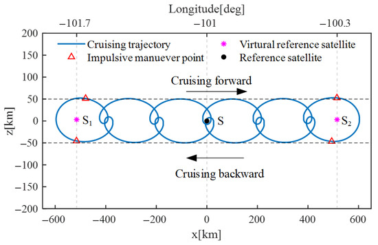
Figure 5.
Trajectory for cruising velocity control strategy.

Table 4.
Velocity impulse strategy for cruising velocity control.
Moreover, as can be seen from Table 4, the magnitude of each velocity impulse is only 0.772 m/s, and the total velocity increment in a cycle of round-trip cruising is only 3.088 m/s. The simulation results demonstrate that the cruising trajectory can be effectively controlled through the proposed cruising velocity strategy. And only a small velocity increment of 3.088 m/s is required to enable the observer to cruise backwards and forwards in a GEO region of about 1000 km.
4.3. Simulation of Combined Velocity and Radius Control Strategy
In this subsection, the combined cruising velocity and radius control strategy is validated. The cruising velocity and cruising radius for the round-trip spiral cruising orbit are listed in Table 5.

Table 5.
Composite control parameters for cruising velocity and cruising radius.
Based on the combined control strategy detailed in Section 3.4, the trajectory of the observer satellite is depicted in Figure 6. It can be seen that the observer satellite cruises between the two boundary longitudes (−100.3 deg and −101.7 deg) after two velocities at each boundary. In addition, the cruising radius of the forward and backward trajectory satisfies the constraints of 50 and 70 km, respectively, revealing that the proposed method is effective for controlling both the cruising velocity and radius.
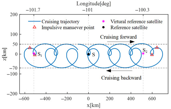
Figure 6.
Trajectory under combined velocity and radius control strategy.
Moreover, the velocity impulses and the corresponding time and positions at each boundary for the control strategy are given in Table 6. As can be seen, the two velocity impulses at each boundary longitude are not equal to each other due to the combined control of cruising velocity and radius. In addition, for both control boundaries, the time duration between two impulses is about 43,000 s, which is about half of the orbital period. The total velocity increment in a round-trip cruise cycle is about 3.086 m/s. The simulation results demonstrate that only a small velocity increment is required to enable the observer to travel between the boundaries with a specific cruising velocity and radius.

Table 6.
Velocity impulse strategy for combined cruising velocity and radius control.
4.4. Simulation of In-Plane, Full-Parameter Control Strategy
In this subsection, the in-plane, full-parameter control strategy is validated. The geometric parameters for the round-trip spiral cruising orbit are presented in Table 7.

Table 7.
Composite control parameters for in-plane, full-parameter control.
According to the in-plane, full-parameter control strategy outlined in Section 3.5, the trajectory of the observer satellite is shown in Figure 7. As can be seen in Figure 7, the observer satellite cruises between the two boundary longitudes after three velocities at each boundary. Moreover, the corresponding impulse conduction details are provided in Table 8. Take the impulse strategy at the boundary of −100.3 deg as an example. The first velocity impulse of 1.552 m/s is implied at the time of 276,436.8 s. Accordingly, the second impulse of 0.171 m/s is conducted after about half of the orbital period with respect to the first impulse. Then, the third impulse of 0.179 is conducted continually after half of the orbital period. The four cruising parameters are successfully controlled by the three impulses. And the total velocity increment required in one round-trip cycle is only 3.445 m/s.
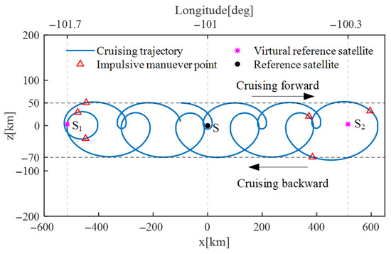
Figure 7.
Trajectory of in-plane, full-parameter control strategy.

Table 8.
Pulse application strategy (in-plane, full-parameter control).
Subsequently, the control process at the two cruising boundaries (−101.7 and −100.3 deg) is visualized in Figure 8 and Figure 9, respectively. Taking Figure 9 as an example, when the sub-satellite longitude of the observer satellite arrives at the boundary −100.3 deg, a virtual reference satellite (the black dot in Figure 9) is created. Based on the backward cruising orbit parameters in Table 7 ( = 200 km/day, = 70 km, , = 20 km), the designed backward cruising trajectory is generated. As can be seen, the green dashed line represents the instantaneous ellipse, and the blue ‘x’ mark represents the position corresponding to the initial phase angle of the observer satellite in the instantaneous ellipse, which is consistent with the constraint . In addition, the triangle marks represent the positions where the control velocity impulses are executed, and the blue solid line and red dash-dotted line represent the actual and designed cruising trajectory of the observer satellite. In can be seen that after three velocity impulses, the two trajectories are finally aligned with each other, which means that the observer satellite is inserted into the desired cruising orbit. These results verify the effectiveness of the in-plane, full-parameter control strategy.
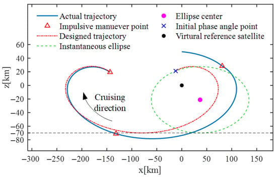
Figure 8.
Boundary control process at the longitude −101.7 deg.
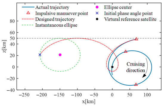
Figure 9.
Boundary control process at the longitude −100.3 deg.
4.5. Comparison with Previous Works
In this subsection, to further evaluate the effectiveness and efficiency of the proposed cruising orbit design and control method, it is compared with the particle swarm optimization cruising orbit design method (PSOCODM) by Zheng, L. et al. [7] for multiple GEO target satellite inspections.
The simulation parameters are presented as follows: The initial sub-satellite longitude of the observer satellite is = 90.0 deg. Three GEO satellites are taken as the targets which are inspected by the observer satellite through the cruising orbit. Denote the three target satellites as targets 1, 2, and 3, respectively. The corresponding sub-satellite longitudes are = 90.2, = 90.5, and = 90.8 deg, respectively. In addition, the closest range between the observer and target satellites is = 10 km, and the simulation duration is = 10.9 days.
In this paper, the idea for determining the cruising orbit of the observer satellite is as follows: First, the inspection time for the three target satellites are given by . Then, three cruising orbits are designed for the inspection of the three target satellites, namely nominal cruising orbits 1, 2, and 3, respectively. For the i-th nominal cruising orbit, assuming that the minimum range constraint is satisfied at time , the corresponding geometric parameters (including the cruising velocity , the cruising radius , the location of the spiral vertex , and the initial in-plane phase angle ) are determined according to the position of the target satellites. Next, for each nominal cruising orbit, the corresponding ROEs can be obtained according to their geometric parameters and Equation (24). Finally, the three-impulse maneuver strategy in Section 3.5 is utilized for the observer satellite to travel between the nominal cruising orbits. As a result, the three target satellites can be finally inspected by the observer satellite.
Subsequently, the cruising trajectories of the observer satellite based on the proposed method and PSOCODM are shown in Figure 10. The corresponding velocity impulse execution details are provided in Table 9. From Figure 10, it can be seen that the cruising trajectories obtained by the two methods are basically similar, and both trajectories satisfy the minimum range constraint = 10 km. From Table 9, it can be seen that the total velocity impulses of the proposed method and PSOCODM are 1.859 and 1.783 m/s, respectively, and the corresponding CPU run time is 0.01 and 1.2 s, respectively. The relative deviation between the impulses of the two methods is only 4.3%, while the run time of the proposed method is only 0.83% of that of PSOCODM. These results demonstrate the efficiency advantage of the proposed cruising orbit design and control method with respect to PSOCODM.
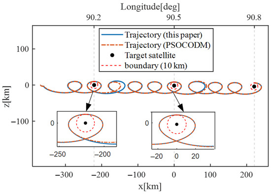
Figure 10.
Trajectories of multiple target cruising orbit.

Table 9.
Pulse application strategy comparison.
5. Conclusions
This paper presents a novel spiral cruising orbit design method based on a set of in-plane geometric parameters and establishes a map between these parameters and the ROEs. Moreover, three analytical and efficient control strategies are developed for round-trip spiral cruising orbit control, including the cruising velocity control strategy, combined cruising velocity and radius control strategy, and the in-plane, full-parameter control strategy. Simulation results demonstrate that the geometry of the GEO spiral cruising orbit can be intuitively described and designed using the proposed in-plane geometric parameters. In addition, only a velocity impulse of 1.5 m/s is required in the boundary longitude to enable the observer satellite to travel in the GEO region at a velocity of about 200 km/day. Moreover, the proposed control strategies are effective for the round-trip spiral cruising orbit control, while reducing over 99% of the run time compared with previous works. Due to their intuitiveness and simplicity, the proposed spiral cruising orbit design and control methods have significant application value for future GEO target monitoring and space situational awareness.
Author Contributions
Conceptualization, Z.L. and S.Z.; methodology, Z.L. and S.Z.; software, Z.L.; validation, J.S., and X.M.; formal analysis, X.M.; investigation, J.S.; resources, J.S.; writing—original draft preparation, Z.L., and S.Z.; writing—review and editing, S.Z., and X.M.; visualization, J.S.; supervision, J.S. All authors have read and agreed to the published version of the manuscript.
Funding
This research received no external funding.
Data Availability Statement
The original contributions presented in this study are included in the article. Further inquiries can be directed to the corresponding author(s).
Conflicts of Interest
The authors declare no conflict of interest.
Appendix A
Based on the in-plane, along-track impulse equations for near-circular orbits [9], the following strategies can be used to correct deviations in ROEs.
Appendix A.1. Correction of Relative Eccentricity Vector
A pair of tangential velocity impulses with the same magnitudes and opposite directions can be used to eliminate the deviation of the relative eccentricity vector , without affecting the relative drift rate . In detail, denote the two impulses as and , respectively. Accordingly, we have
The first velocity impulse and the corresponding latitude argument of the reference satellite is given by
However, the mean arguments of latitude difference will be changed due to the two impulses. The change in is given by
Appendix A.2. Correction of Relative Drift Rate
A pair of tangential velocity impulses with the same magnitudes and directions can eliminate the deviations in the relative drift rate without affecting the relative eccentricity vector. Denote the two impulses as and ; then, we have
The first impulse is given by
It should be noted that the first impulse can be executed at any argument of latitude of the reference satellite. The resulting change in the initial mean arguments of latitude difference is given by
Appendix A.3. Correction of Mean Argument of Latitude Difference
A pair of impulses with the same magnitudes and opposite directions can be used to correct the deviations in the initial mean argument of latitude difference when the phase angles of the maneuver points are equal to each other. And no changes are produced for the relative drift rate and relative eccentricity vector. In detail, denote the two impulses as and ; then, we have
The first impulse used to eliminate the deviation of the initial mean arguments of latitude difference is given by
where and are given by (A3) and (A6), respectively.
Appendix A.4. Three-Pulse Tangential Impulse Strategy
The complete three-impulse, along-track maneuver strategy for correcting the deviations of the in-plane ROEs is summarized in Table A1.

where represents the argument of latitude of the reference satellite
or

Table A1.
Three-impulse tangential ROE correction strategy.
Table A1.
Three-impulse tangential ROE correction strategy.
| Impulse Sequence | Impulse | Calculation Formula | Execution Time |
|---|---|---|---|
| 1 | |||
| 2 | |||
| 3 |
References
- Huang, J.; Lei, X.; Zhao, G.; Liu, L.; Li, Z.; Luo, H.; Sang, J. Short-Arc Association and Orbit Determination for New Geo Objects with Space-Based Optical Surveillance. Aerospace 2021, 8, 298. [Google Scholar] [CrossRef]
- Luo, Y.-Z.; Sun, Z.-J.; Zhang, J. Proximity Scenario Design for Geostationary Rendezvous with Collocated Satellite Avoidance. Acta Astronaut. 2019, 154, 153–168. [Google Scholar] [CrossRef]
- Beigelman, I.; Gurfil, P. Optimal Geostationary Satellite Collocation Using Relative Orbital Element Corrections. J. Spacecr. Rocket. 2009, 46, 141–150. [Google Scholar] [CrossRef]
- Yates, J.M.; Spanbauer, B.W.; Black, J.T. Geostationary Orbit Development and Evaluation for Space Situational Awareness. Acta Astronaut. 2012, 81, 256–272. [Google Scholar] [CrossRef]
- Sullivan, J.; Grimberg, S.; D’Amico, S. Comprehensive survey and assessment of spacecraft relative motion dynamics models. J. Guid. Control Dyn. 2017, 40, 1837–1859. [Google Scholar] [CrossRef]
- Zhang, Y.; Xu, Y.; Zhou, H. Theory and design method of spiral cruising orbit. In Theory and Design Methods of Special Space Orbits; Springer: Singapore, 2016; pp. 91–137. [Google Scholar]
- Zheng, L.; Feng, F.; Xu, Y. Optimization of Cruise Tourist Orbit for Multiple Targets on GEO. In Proceedings of the 2016 3rd International Conference on Management, Education Technology and Sports Science (METSS 2016), Guilin, China, 24–25 September 2016; Atlantis Press: Guilin, China, 2016. [Google Scholar]
- Zhou, H.J. Study of Spiral Cruising Surveillance Orbit for GEO Debris. J. Beijing Inst. Technol. 2016, 25, 68–72. [Google Scholar]
- Xu, Y.L.; Zhou, H.J.; Dai, H.Y.; Zhou, H.; Dai, H. Design of GEO Helix Tourist Orbit Based on Perturbation Compensation. In Proceedings of the AIP Conference Proceedings, Hangzhou, China, 15–16 April 2017. [Google Scholar]
- Chen, N.; Zhang, Y.; Xue, W. A traverse inspection constellation for GEO quasi-stationary satellites. IEEE Access 2024, 12, 132096–132106. [Google Scholar] [CrossRef]
- Chen, N.; Zhang, Z.; Feng, S.; Xue, W.; Jia, B. A patrol route design for inclined geosynchronous orbit satellites in space traffic management. Aerospace 2025, 12, 299. [Google Scholar] [CrossRef]
- Han, C.; Yin, J. Formation design in elliptical orbit using relative orbit elements. Acta Astronaut. 2012, 77, 34–47. [Google Scholar] [CrossRef]
- He, Q.; Han, C. Dynamics and Control of Satellite Formation Flying Based on Relative Orbit Elements. In Proceedings of the AIAA Guidance, Navigation and Control Conference and Exhibit, Honolulu, HI, USA, 18 August 2008. [Google Scholar]
- Yin, J.; Han, C. Elliptical formation control based on relative orbit elements. Chin. J. Aeronaut. 2013, 26, 1554–1567. [Google Scholar] [CrossRef]
- Bai, S.; Wang, Y.; Liu, H.; Sun, X. Spacecraft Fast Fly-around Formations Design Using the Parallelogram Configuration. Nonlinear Dyn. 2025, 113, 1041–1062. [Google Scholar] [CrossRef]
- Bai, S.; Wang, Y.; Cheng, M.; Sun, X.; Xu, M. Analytical Sensitivity Matrix for Near-Optimal Solution to Elliptical Orbit Transfer. IEEE Trans. Aerosp. Electron. Syst. 2025, 1–21. [Google Scholar] [CrossRef]
- Bai, S.; Wang, Y.; Liu, H.; Sun, X. Finite-Thrust Lambert Transfer Based on Multistage Constant-Vector Thrust Control. IEEE Trans. Aerosp. Electron. Syst. 2023, 59, 4947–4967. [Google Scholar] [CrossRef]
- Sun, X.; Wang, Y.; Su, J.; Li, J.; Xu, M.; Bai, S. Relative Orbit Transfer Using Constant-Vector Thrust Acceleration. Acta Astronaut. 2025, 229, 715–735. [Google Scholar] [CrossRef]
- Bai, S.; Chen, H.; Zhang, S.; Geng, C.; Han, C.; Xu, M. Exoatmospheric intercept guidance based on relative-motion control with respect to zero-effort orbit. Space Sci. Technol. 2024, 4, 0112. [Google Scholar] [CrossRef]
- Chen, H.; Zhao, H.; Han, C.; Ma, Y.; Bai, S. Bounded impulse-control hovering formation in elliptical orbits. Acta Astronaut. 2024, 219, 917–930. [Google Scholar] [CrossRef]
Disclaimer/Publisher’s Note: The statements, opinions and data contained in all publications are solely those of the individual author(s) and contributor(s) and not of MDPI and/or the editor(s). MDPI and/or the editor(s) disclaim responsibility for any injury to people or property resulting from any ideas, methods, instructions or products referred to in the content. |
© 2025 by the authors. Licensee MDPI, Basel, Switzerland. This article is an open access article distributed under the terms and conditions of the Creative Commons Attribution (CC BY) license (https://creativecommons.org/licenses/by/4.0/).