Abstract
In modern laptops, antenna design for Wi-Fi 7 is constrained by limited space and reduced ground plane size, conditions under which many compact designs exhibit degraded bandwidth or efficiency or require large device grounds. This paper presents a miniaturized tri-band inverted-F antenna (IFA) that supports the 2.4, 5, and 6 GHz Wi-Fi 7 bands within a radiator area of 20 × 5 × 0.8 mm3 and a ground plane of 60 × 40 mm2. The proposed design achieves wideband impedance matching and stable radiation efficiency under intentionally reduced grounding conditions, addressing a scenario rarely considered in prior studies where both radiator and ground plane miniaturization must be satisfied. Measurements confirm efficiencies of 74–81% at 2.4 GHz and 64–90% across 5–7 GHz, with performance in the lower band exceeding that of many compact designs and upper-band coverage comparable to structures requiring larger footprints. By demonstrating tri-band operation under simultaneous radiator and ground reduction, this work provides a practical antenna solution for next-generation Wi-Fi 7 laptop integration.
1. Introduction
The evolution of wireless local area network (WLAN) technology has been driven by increasing requirements for data throughput, spectrum efficiency, and low-latency connectivity in congested environments. Early Wi-Fi standards, formalized under IEEE 802.11 in the late 1990s, operated exclusively in the 2.4 GHz band [1], providing adequate coverage and compatibility for initial consumer applications. With the rapid growth of network traffic, the limitations of the 2.4 GHz spectrum prompted adoption of the 5 GHz band [2], which enabled wider channel bandwidths and improved interference isolation. This transition was realized through standards such as IEEE 802.11a, 802.11n, and 802.11ac [3]. Continued expansion of connected devices, video streaming, and latency-sensitive applications eventually made dual-band operation insufficient. IEEE 802.11ax, branded as Wi-Fi 6E, introduced support for the 6 GHz band, adding 1.2 GHz of unlicensed spectrum [4]. Building on this foundation, IEEE 802.11be (Wi-Fi 7) consolidates simultaneous operation across 2.4, 5, and 6 GHz bands and incorporates new features such as 320 MHz channelization, 4096-QAM, and multi-link operation to support high-throughput and low-latency communication in dense device environments [5].
To meet these requirements, laptop-integrated antennas must provide consistent impedance matching across all three Wi-Fi 7 bands, sufficient radiation efficiency in compact enclosures, and limited sensitivity to surrounding metallic structures and noise sources. Early laptop antennas were typically single-band monopole, dipole, or loop structures designed for the 2.4 GHz band [6]. As dual-band operation became standard under IEEE 802.11n and 802.11ac, inverted-F antennas (IFAs) and folded structures were introduced to cover both 2.4 GHz and 5 GHz within narrow edge spaces [7,8,9,10,11,12,13]. With the extension to the 6 GHz band under Wi-Fi 6E and Wi-Fi 7, broader impedance bandwidth and enhanced frequency selectivity are required. Most reported solutions achieve radiator miniaturization but rely on relatively large ground planes to sustain acceptable radiation performance. In practice, thin and component-dense laptops often restrict available ground area, making it necessary to evaluate antenna behavior when both the radiator and the ground plane are constrained.
Recent designs for Wi-Fi 6E and Wi-Fi 7 antennas address multiband operation through a variety of strategies. Bandwidth enhancement has been achieved using metamaterial-inspired elements with interdigital capacitors and shorting strips to excite zeroth-order resonance modes [14] or modified inverted-L radiators with coupled-fed networks for compact dual-band operation [15]. Hybrid topologies integrating slot, dipole, and monopole elements have been used to extend coverage across all three bands [16]. Other studies emphasize geometric adaptability, such as folded IFAs optimized for bezel-limited regions [17] or monopoles miniaturized with chip inductors [18]. For multi-antenna platforms, conjoined layouts [19] and asymmetric isolation-enhanced structures [20] have been proposed to improve inter-element performance. Multi-feed configurations have also been explored to achieve continuous tri-band coverage in narrow bezels spanning 2.4–7.125 GHz [21]. More recent reports address Wi-Fi 6E/7 laptop and terminal antennas through display-edge closed-slot/T-feed arrays, metamaterial/zeroth-order-resonance miniaturization, hinge-region layouts for metal housings, and wideband/circularly polarized and wearable implementations spanning 2.4/5/6 GHz [22,23,24,25,26]; however, most assume standard or extended grounds or emphasize array layout, whereas concurrent radiator and ground-plane miniaturization remains less examined and is specifically addressed here.
This study proposes a tri-band antenna specifically designed for Wi-Fi 7 laptops, covering the 2.40–2.48 GHz, 5.15–5.85 GHz, and 5.925–7.125 GHz bands, corresponding to bandwidths of 80 MHz, 700 MHz, and 1.2 GHz, respectively. Unlike previous designs that assume extensive ground support, the proposed antenna is optimized to sustain impedance matching and radiation efficiency under constrained grounding. A systematic parameter analysis identifies the resonant mechanisms and guides geometric tuning. The design is fabricated and validated through full-wave simulation and experimental measurements, including reflection coefficient, radiation efficiency, and gain. Results confirm consistent tri-band operation without requiring full-sized ground or auxiliary isolation structures, addressing the gap between idealized radiator studies and practical laptop integration.
2. Antenna Structure and Design Methodology
This work develops a tri-band antenna structure tailored for Wi-Fi 7 laptop integration under constrained radiator and ground plane conditions. The design targets the IEEE 802.11be frequency allocations: 2.40–2.48 GHz, 5.15–5.85 GHz, and 5.925–7.125 GHz, with the 6 GHz band spanning a wide 1.2 GHz. To ensure consistent coverage, the impedance matching criterion is set to −7.4 dB, corresponding to a maximum input reflection of 25%, which is commonly adopted in compact device antenna evaluations. For radiation efficiency, thresholds follow commercial laptop RF design guidelines: ≥31.62% (−5 dB) at 2.4 GHz and ≥28.18% (−5.5 dB) across 5.15–7.125 GHz, providing margin for fabrication tolerances and packaging losses. These criteria frame the antenna’s optimization under the dual constraint of radiator and ground plane miniaturization.
2.1. Antenna Geometry
The proposed structure adopts an IFA configuration, selected for its suitability in confined layouts while enabling quarter-wavelength resonance with a shorting element. Figure 1 illustrates the geometry. The antenna is realized on a single-layer FR4 substrate (dielectric constant εᵣ = 4.4, loss tangent tanδ = 0.02, thickness = 0.8 mm), representing a low-cost PCB technology compatible with laptop integration. The radiator footprint is limited to 20 mm × 5 mm, while the ground plane is constrained to dimensions of GNDy × GNDx, where GNDy = 60 mm and GNDx = 40 mm, both intentionally minimized to replicate space-restricted device conditions. A sideview schematic of the antenna geometry, including the substrate thickness of 0.8 mm, is shown in Figure 1c.
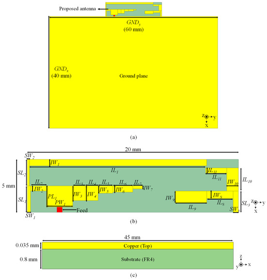
Figure 1.
Geometry of the proposed antenna: (a) radiator and reduced ground plane; (b) segment labeling for feed, shorting, and radiating arm; (c) sideview of the proposed antenna structure.
The antenna consists of three functional regions: the feed patch, the shorting path, and the radiating arm. The feed patch, defined by parameters PW1 and PL1, introduces a 50 Ω excitation at the lower-left substrate corner. Adjacent to it, a vertical shorting strip connects directly to the ground plane, establishing the low-impedance return path that enforces quarter-wavelength resonance.
The radiating arm is implemented as a stepped meandered line, combining horizontal (IL1–IL11) and vertical (IW1–IW10) segments within the 5 mm height constraint. The central folded section (IL1–IL7, IW1–IW7) generates the 2.4 GHz and 5 GHz resonances. Local vertical stubs (e.g., IW4–IW6) perturb the impedance locally, improving bandwidth and modal selectivity. The terminal section (IL8–IL10, IW8–IW9) produces additional higher-order modes that enable 6 GHz coverage, with offsets IL8 and IW8 providing capacitive coupling and secondary loops that reinforce broadband behavior.
SW1–SW3 (horizontal) and SL1–SL3 (vertical) denote the geometric parameters of the physical conductors that connect the radiator to the ground plane. These shorting elements provide current return paths and influence the modal tuning across the operating bands. The final structure achieves full tri-band capability within the reduced 20 mm × 5 mm radiator area without vias or multilayer routing, addressing the ground-plane-constrained scenario.
2.2. Operating Principles
To clarify the physical mechanisms underlying the tri-band response, simulated surface current distributions at 2.4, 5.5, and 6.5 GHz are shown in Figure 2.
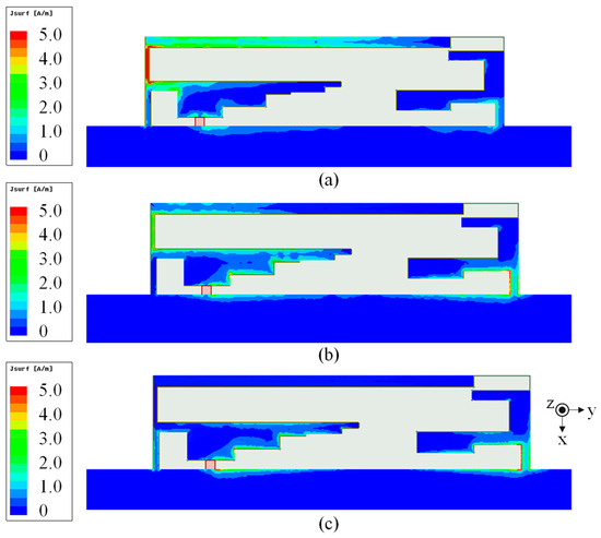
Figure 2.
Simulated surface current distributions of the proposed IFA at (a) 2.45 GHz, (b) 5.5 GHz, and (c) 6.5 GHz.
At 2.4 GHz, the dominant resonance is established by a quarter-wavelength loop extending from the feed patch through the shorting strip into the initial horizontal segments (IL1–IL3), with strong current density between the feed and the shorting point. This confirms the fundamental IFA resonance under limited ground size.
At 5.5 GHz, resonance occurs through the extended meandered midsection (IL3–IL7), which elongates the current path without enlarging the footprint. The stub SL2 interrupts current continuity, acting as a localized impedance transformer that generates multiple standing-wave lobes. This introduces additional resonance while preserving compactness.
At 6.5 GHz, the terminal lines (IL8–IL10, IW8–IW9) form the primary path, with shortened lengths and angular folds introducing localized high-impedance zones. These establish the boundary conditions for stable excitation of higher-order modes within the upper band, as shown in Figure 2c. The distinct segmentation of resonant regions confirms that the antenna achieves tri-band operation by distributing modal control across separate radiator sections.
2.3. Parametric Studies
To quantify the contribution of key geometric parameters, a set of five variables was analyzed: feed arm width (PW1), front radiator length (IL1), shorting width (SW1), midsection length (IL3), and terminal shorting width (SW3). Each was varied independently, and the reflection coefficient response was recorded.
Figure 3 shows that increasing PW1 from 1.5 mm to 3.5 mm shifts the 5 GHz resonance upward and reduces the depth of the matching dip. Narrower PW1 enhances coupling, producing deeper but lower-frequency resonance, while wider PW1 diffuses current and weakens excitation. Its effect is localized to the mid-band, with negligible influence on the 2.4 and 6.5 GHz resonances.
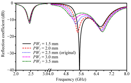
Figure 3.
Simulated reflection coefficient variations with parameter PW1.
Figure 4 demonstrates that extending IL1 from 15.2 mm to 18.4 mm shifts the 2.4 GHz resonance downward, consistent with the longer current path of the fundamental mode. Secondary effects occur at 5 GHz, where IL1 contributes to higher-order resonances. IL1 is therefore the primary tuning parameter for the low band.
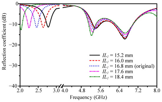
Figure 4.
Simulated reflection coefficient variations with parameter IL1.
As shown in Figure 5, increasing SW1 from 0.3 mm to 2.3 mm degrades the 6.5 GHz resonance, reducing matching depth and shifting frequency. Excessive width enlarges the current injection region, disrupting field confinement at high frequency. Effects on 5 GHz are moderate, while at 2.4 GHz a slight deterioration in impedance matching can also be observed. Therefore, SW1 acts mainly as a stabilizer for grounding and high-band control, but its influence is not completely negligible at the low band.
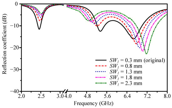
Figure 5.
Simulated reflection coefficient variations with parameter SW1.
Figure 6 shows that increasing IL3 from 0.8 mm to 1.6 mm shifts the 5 GHz resonance downward, extending the electrical length. Shorter IL3 configurations suppress resonance due to abrupt truncation. IL3 is confirmed as the main tuning parameter for mid-band operation.
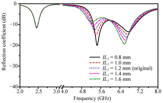
Figure 6.
Simulated reflection coefficient variations with parameter IL3.
Lastly, Figure 7 indicates that increasing SW3 slightly reduces resonance depth at 6.5 GHz, while frequency shift remains small. Broader SW3 disperses current, lowering coupling strength at high frequency. SW3 is therefore a secondary but useful fine-tuning element for high-band matching in dense layouts.
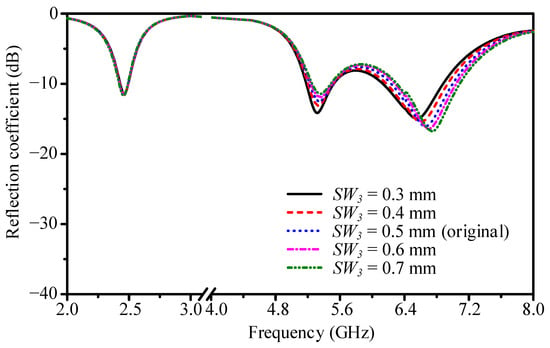
Figure 7.
Simulated reflection coefficient variations with parameter SW3.
Figure 8 shows the variation in antenna performance with respect to GNDy. At the 2.4 GHz band, the resonance frequency remains stable as the ground width is reduced, although the matching depth becomes slightly weaker. This behavior arises because a narrower ground increases the effective inductance in the return path, which elevates the input impedance seen by the fundamental mode. While this degradation is modest, it indicates that excessive reduction of GNDy gradually diminishes the low-band matching. In the 5 GHz band, the effect becomes more pronounced: as GNDy decreases, the counterpoise support from the ground is weakened, causing the second-order resonance to lose depth and bandwidth. The high-frequency band around 6–7 GHz is the most sensitive to ground width. A smaller GNDy not only reduces the depth of the resonance but also shifts its frequency upward, as the higher-order modes are strongly dependent on edge fringing fields at the ground boundary. Truncating the ground along the y direction shortens the effective resonant path and pulls the mode away from the intended value. These results confirm that a ground width of 60 mm is the smallest value that still preserves continuous tri-band coverage under the −7.4 dB criterion. Any further reduction leads to unacceptable deterioration, particularly in the mid- and high-band responses.
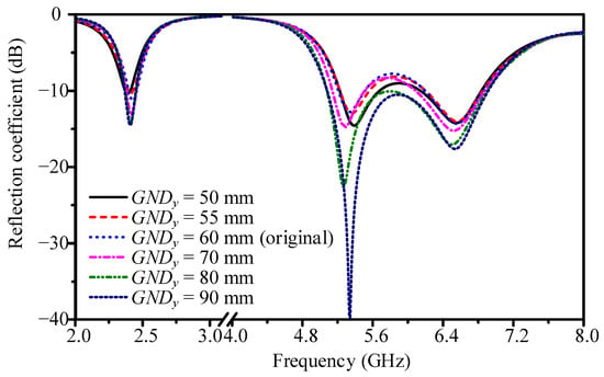
Figure 8.
Simulated reflection coefficient variations with parameter GNDy.
Figure 9 illustrates the effect of varying GNDx. In contrast to GNDy, the influence of ground length is much weaker. At 2.4 GHz, the resonance frequency and matching depth are essentially unchanged when GNDx is varied, as the fundamental quarter-wavelength mode is dominated by vertical return currents close to the shorting strip rather than long horizontal extensions. At 5 GHz, only minor variations are observed, with the matching dip remaining below −7.4 dB across the tested range. At 6–7 GHz, there are small changes in matching depth, which can be attributed to weak interactions between higher-order modes and the ground edge capacitance along the x direction. However, these effects are secondary compared with the strong dependence on GNDy. Overall, the antenna is robust to variations in GNDx, meaning the ground length can be kept as short as 40 mm without compromising tri-band operation. This compactness along the x direction is especially important in laptop layouts where space is heavily constrained by other components.
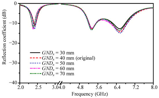
Figure 9.
Simulated reflection coefficient variations with parameter GNDx.
Together, the parametric studies confirm that IL1 and IL3 directly define the low- and mid-band resonances, respectively, while PW1 controls feed coupling that shapes mid-band impedance. SW1 stabilizes grounding and SW3 adjusts field confinement at the radiator end, both influencing high-frequency operation. In addition, the ground dimensions play a critical role: GNDy determines whether sufficient bandwidth and matching can be maintained in the 5–7 GHz region, while GNDx shows only weak influence across all bands, allowing the ground length to be kept compact without compromising performance. Effective tri-band performance therefore requires coordinated tuning of path-defining lengths, coupling elements, and the reduced ground size, especially under reduced ground conditions where modal interactions are more sensitive.
3. Antenna Performance
To verify the impedance matching and tri-band operation of the proposed IFA, both simulations and measurements were conducted. The prototype was fabricated following the same dimensions used in simulation. The evaluation criterion for acceptable matching was a reflection coefficient below −7.4 dB (VSWR = 2.5:1), a commonly applied threshold in compact wireless antenna systems.
The fabricated prototype is shown in Figure 10. A polystyrene block provided structural support, while copper foil formed the radiator and ground plane. A 9 GHz-rated IPEX-I(M)-SMA(F) connector and a 10 cm low-loss coaxial cable were used for feeding. During measurements, the prototype was placed on a polystyrene pad to minimize external coupling. The reflection coefficient was recorded using a vector network analyzer (VNA) from 2 to 7 GHz.
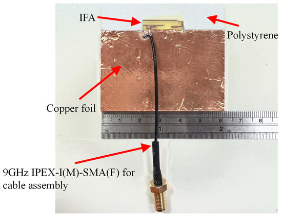
Figure 10.
Fabricated prototype of the proposed IFA. The copper foil ground plane has a length of 60 mm, consistent with the design model. The polystyrene block serves only as mechanical support and does not extend the electrical ground plane.
The measured and simulated reflection coefficients are compared in Figure 11. Three resonant modes were observed near 2.4 GHz, 5.5 GHz, and 6.5 GHz. Simulated minima reached −11. 6 dB, −12.5 dB, and −16.1 dB, respectively. The measured data preserved all three resonances, with reflection coefficients below −6 dB at 2.4 GHz and below −7.4 dB at 5.5 GHz and 6.5 GHz.
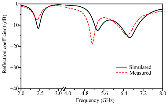
Figure 11.
Simulated and measured reflection coefficient of the proposed antenna.
A downward frequency shift of about 100 MHz was observed in all measured resonances. Likely causes include geometric variation from the copper foil and substrate thickness, parasitic inductance introduced by the SMA connector, and environmental scattering during measurement. Despite these influences, the measured bandwidths and resonance depths followed the simulated trends, confirming that the antenna design is reproducible under practical fabrication.
Radiation performance was measured in an anechoic chamber. Far-field results for realized gain patterns, efficiency, and peak gain were obtained at 2.45, 5.5, and 6.5 GHz and compared with simulations.
Figure 12, Figure 13 and Figure 14 show the 2D realized gain patterns in the x–z and y–z planes. At 2.45 GHz, the radiation in the x–z plane was quasi-omnidirectional, with half-power beamwidth (HPBW) of 288° in simulation and 250° in measurement. The cross-polarization discrimination (XPD) was 2.5 dB. In the y–z plane, the HPBW narrowed to 74° (simulation) and 70° (measurement), with XPD of 2.1 dB. This indicates broad angular coverage at low frequency, with limited polarization purity.
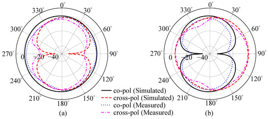
Figure 12.
Simulated and measured realized gain patterns of the proposed antenna at 2.4 GHz on (a) x–z plane and (b) y–z plane. Unit: dBi.
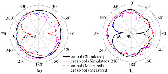
Figure 13.
Simulated and measured realized gain patterns of the proposed antenna at 5.5 GHz on (a) x–z plane and (b) y–z plane. Unit: dBi.
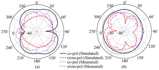
Figure 14.
Simulated and measured realized gain patterns of the proposed antenna at 6.5 GHz on (a) x–z plane and (b) y–z plane. Unit: dBi.
At 5.5 GHz, the x–z plane beamwidth widened to 332° in simulation and 340° in measurement, while XPD improved to 11.2 dB. In the y–z plane, HPBW was 64° and 70°, with XPD reaching 20.3 dB. These results show stronger main polarization and reduced cross-polarization compared with the 2.4 GHz band.
At 6.5 GHz, the x–z plane beamwidth narrowed to 104° (simulation) and 120° (measurement), with XPD of 7.7 dB. In the y–z plane, beamwidth expanded to 244° and 310°, while XPD decreased to 5.4 dB. The wider spread reflects the higher-order modes, which generate more complex and less symmetric field distributions.
Radiation efficiency is summarized in Figure 15. Simulated efficiencies were about 80% at 2.4 GHz and 75% in both higher bands. Measured values were 50–60% at 2.4 GHz and 50–80% across 5–7 GHz. The reduction is attributed to conductor and substrate losses, connector parasitics, and environmental factors. Measured results remain consistent with compact PCB-based antenna performance. While FR4 was adopted in this work to reflect cost-effective manufacturing, further efficiency improvements can be obtained by employing a lower-loss dielectric. Connector parasitics and temporary support structures also contribute to the measured reduction, which would be mitigated in final laptop integration through direct PCB feeding and optimized enclosure design. Nevertheless, the measured efficiencies of 50–60% at 2.4 GHz and 50–80% across 5–7 GHz already meet commercial WLAN antenna requirements, demonstrating that the proposed design offers a practical balance between low-cost implementation and reliable Wi-Fi 7 performance.
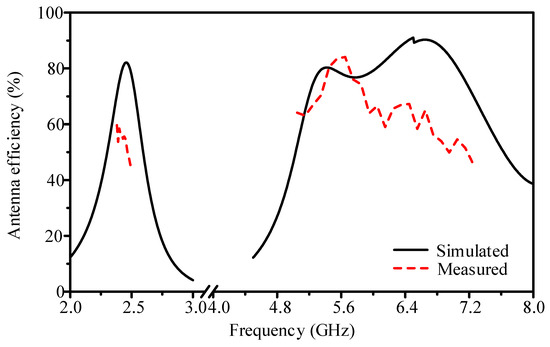
Figure 15.
Simulated and measured radiation efficiency of the proposed antenna.
Figure 16 shows the measured realized peak gains. At 2.4 GHz, the gain ranged from 0.6 to 1.4 dBi. At 5 GHz and 6 GHz, it increased to 3.0–5.3 dBi. The simulated and measured realized peak gains (reported in dBi) differed by less than 1 dB in all cases, confirming the stability of the tri-band operation.
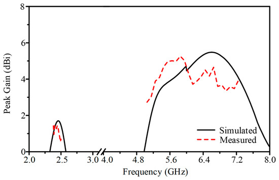
Figure 16.
Simulated and measured realized peak gain of the proposed antenna.
Table 1 compares the proposed antenna with reported Wi-Fi 7 designs. Bandwidth definitions in the literature vary: some use −10 dB, others −6 dB, and some −7.4 dB. In terms of impedance bandwidth, the proposed antenna achieves a continuous bandwidth of 2.390–2.527 GHz in the lower band and 5.142–7.167 GHz in the upper band, fully covering the 802.11b/g/n and Wi-Fi 6E frequency allocations. Compared to prior works that either offer narrower bandwidths [14,16,18,19] or use more relaxed −6 dB criteria [15,16,19], the current design provides wider operating margins under a more stringent specification.

Table 1.
Comparison of recent Wi-Fi 7 antenna designs.
Regarding radiation efficiency, the proposed structure exhibits 74–81% efficiency at 2.4 GHz and 64–90% in the 5–7 GHz range. These results outperform or match the upper-band efficiency reported in [14,16,18], while also exceeding the lower-band values found in [17,18,21]. While [20] achieves higher upper-band performance (77–86%), its footprint is notably larger.
In terms of physical size, the proposed design occupies 20.0 × 5.0 × 0.8 mm3, which balances compactness and performance. Compared to more compact structures such as [18,21], which adopt ultra-thin 0.4 mm substrates, the proposed antenna offers improved radiation performance while maintaining a thin-profile design suitable for laptop integration. Designs with similar or larger footprints, such as [14,16,20], do not consistently demonstrate simultaneous advantages in bandwidth and efficiency across all three Wi-Fi 7 bands.
In addition to radiator dimensions and bandwidth, Table 1 also includes the ground-plane sizes reported in earlier studies. It can be seen that most Wi-Fi 6E and Wi-Fi 7 antennas were validated on extended grounds such as 315 × 182 mm2, 300 × 200 mm2, or 260 × 200 mm2, which are more than twenty times larger in area than the compact 60 × 40 mm2 ground adopted in this work. The proposed antenna therefore demonstrates stable tri-band operation not only with a miniaturized radiator but also with a significantly reduced ground plane. This distinction highlights the novelty of the present design, where both the radiator and the ground are simultaneously constrained, directly addressing realistic laptop integration scenarios that earlier studies did not emphasize.
In summary, the proposed antenna design combines a compact footprint with tri-band coverage, competitive radiation efficiency, and a stricter impedance matching threshold. This performance combination is rarely achieved in the existing literature and supports practical integration in constrained device environments such as laptop enclosures.
4. Conclusions
This study presented a compact tri-band IFA for Wi-Fi 7 laptops that simultaneously addresses radiator miniaturization and reduced ground plane availability. Implemented within a 20 × 5 × 0.8 mm3 radiator and a 60 × 40 × 0.8 mm3 ground plane, the antenna achieves efficiencies of 74–81% at 2.4 GHz and 64–90% across 5–7 GHz, meeting a −7.4 dB matching criterion. Compared with existing compact designs, it demonstrates improved efficiency in the lower band and comparable upper-band coverage without relying on larger ground structures. The academic contribution lies in establishing and validating a design approach that ensures multiband performance under dual miniaturization constraints, thereby bridging the gap between compact radiator concepts and practical antenna integration in Wi-Fi 7 laptop platforms.
Author Contributions
Y.-K.H.: Data Curation, Formal Analysis, Investigation, Methodology, Validation. K.-H.T.: Funding Acquisition, Project Administration, Conceptualization. Y.-S.C.: Supervision, Writing—Original Draft Preparation, Writing—Review and Editing. All authors have read and agreed to the published version of the manuscript.
Funding
This work was supported in part by the National Science and Technology Council (NSTC), Taiwan, under Contract NSTC 113-2221-E-027-085-MY3, and in part by Micro-Star International Co., Ltd., under industry-academia collaboration projects.
Data Availability Statement
The data presented in this study are contained within the article.
Conflicts of Interest
Author Kuan-Hsueh Tseng is employed by Micro-Star International Co., Ltd. The authors declare that this study received funding from Micro-Star International Co., Ltd. under an industry-academia collaboration project. Author Kuan-Hsueh Tseng contributed to funding acquisition, project administration, and conceptualization. The funders did not influence the study design, data collection, data analysis, data interpretation, or the decision to submit the article for publication. The remaining authors declare that the research was conducted in the absence of any additional commercial or financial relationships that could be construed as a potential conflict of interest.
References
- Hiertz, G.R.; Denteneer, D.; Stibor, L.; Zang, Y.; Costa, X.P.; Walke, B. The IEEE 802.11 universe. IEEE Commun. Mag. 2010, 48, 62–70. [Google Scholar] [CrossRef]
- Noghanian, S. Dual-band wearable MIMO antenna for WiFi sensing applications. Sensors 2022, 22, 9257. [Google Scholar] [CrossRef] [PubMed]
- Karmakar, R.; Chattopadhyay, S.; Chakraborty, S. Impact of IEEE 802.11n/ac PHY/MAC high throughput enhancements on transport and application protocols—A survey. IEEE Commun. Surv. Tutor. 2017, 19, 2050–2091. [Google Scholar] [CrossRef]
- Khorov, E.; Kiryanov, A.; Lyakhov, A.; Bianchi, G. A tutorial on IEEE 802.11ax high efficiency WLANs. IEEE Commun. Surv. Tutor. 2019, 21, 197–216. [Google Scholar] [CrossRef]
- Frascolla, V.; Cavalcanti, D.; Shah, R. Wi-Fi evolution: The path towards Wi-Fi 7 and its impact on IioT. J. Mob. Multimed. 2023, 19, 263–276. [Google Scholar] [CrossRef]
- Lai, F.-P.; Mi, S.-Y.; Chen, Y.-S. Design and integration of millimeter-wave 5G and WLAN antennas in perfect full-screen display smartphones. Electronics 2022, 11, 957. [Google Scholar] [CrossRef]
- Chen, J.; Tong, K.F.; Al-Armaghany, A.; Wang, J. A dual-band dual-polarization slot patch antenna for GPS and Wi-Fi applications. IEEE Antennas Wirel. Propag. Lett. 2016, 15, 406–409. [Google Scholar] [CrossRef]
- Xiao, Y.; Qi, Y.; Li, F.; Fan, J.; Yu, W.; Lu, L. Dual-band directional slot antenna for Wi-Fi application. IEEE Trans. Antennas Propag. 2018, 66, 4277–4281. [Google Scholar] [CrossRef]
- Wang, Z.; Wang, M.; Nie, W. Design of a dual-band WiFi antenna using the theory of characteristic modes and nested Chinese characters. Electronics 2023, 12, 3465. [Google Scholar] [CrossRef]
- Jeong, G.T.; Kim, W.S.; Kwak, K.S. Dual-band Wi-Fi antenna with a ground stub for bandwidth enhancement. IEEE Antennas Wirel. Propag. Lett. 2012, 11, 1036–1039. [Google Scholar] [CrossRef]
- Xu, Z.; Ding, C.; Zhou, Q.; Sun, Y.; Huang, S. A dual-band dual-antenna system with common-metal rim for smartphone applications. Electronics 2019, 8, 348. [Google Scholar] [CrossRef]
- Paul, L.C.; Saha, H.K.; Rani, T.; Azim, R.; Islam, M.T.; Samsuzzaman, M. A dual-band semi-circular patch antenna for WiMAX and WiFi-5/6 applications. Int. J. Commun. Syst. 2023, 36, e5357. [Google Scholar] [CrossRef]
- Sarkar, D.; Srivastava, K.V. Compact four-element SRR-loaded dual-band MIMO antenna for WLAN/WiMAX/WiFi/4G-LTE and 5G applications. Electron. Lett. 2017, 53, 1623–1624. [Google Scholar] [CrossRef]
- Su, S.-W.; Magray, M.I.; Lu, J.-H. Metamaterial-inspired antenna for Wi-Fi 7 operation in wireless local area network bands. In Proceedings of the 2023 Asia-Pacific Microwave Conference (APMC), Taipei, Taiwan, 5–8 December 2023; pp. 76–79. [Google Scholar]
- Sim, C.-Y.-D.; Ju, J.-W.; Chuang, P.-Y.; Chen, W.-C.; Chen, M.-G. A low profile laptop antenna design for Wi-Fi 7 operations. In Proceedings of the 2023 Asia-Pacific Microwave Conference (APMC), Taipei, Taiwan, 5–8 December 2023; pp. 539–541. [Google Scholar]
- Magray, M.I.; Su, S.-W.; Lu, J.-H. Compact, hybrid slot-dipole-monopole Wi-Fi 7 antenna for slim-bezel notebook applications. In Proceedings of the 2023 Asia-Pacific Microwave Conference (APMC), Taipei, Taiwan, 5–8 December 2023; pp. 28–30. [Google Scholar]
- Sim, C.-Y.-D.; Kulkarni, J.; Wang, S.-H.; Zheng, S.-Y.; Lin, Z.-H.; Chen, S.-C. Low-profile laptop antenna design for Wi-Fi 6E band. IEEE Antennas Wirel. Propag. Lett. 2023, 22, 79–83. [Google Scholar] [CrossRef]
- Su, S.-W. Compact, small, chip-inductor-loaded Wi-Fi 6E monopole antenna. In Proceedings of the 2021 IEEE International Symposium on Antennas and Propagation and USNC-URSI Radio Science Meeting (APS/URSI), Singapore, 4–10 December 2021; pp. 937–938. [Google Scholar]
- Su, S.-W.; Yusuf, D.P.; Chu, F.-H. Conjoined, Wi-Fi 6E MIMO antennas for laptops. In Proceedings of the 2021 International Symposium on Antennas and Propagation, Taipei, Taiwan, 19–22 October 2021; pp. 1–3. [Google Scholar]
- Su, S.-W.; Wan, C.-C. Asymmetrical, self-isolated laptop antenna in the 2.4/5/6 GHz Wi-Fi 6E bands. In Proceedings of the 2021 International Symposium on Antennas and Propagation, Taipei, Taiwan, 19–22 October 2021; pp. 1–2. [Google Scholar]
- Jhang, W.-C.; Sun, J.-S. Small antenna design of triple band for Wi-Fi 6E and WLAN applications in the narrow border laptop computer. Int. J. Antennas Propag. 2021, 2021, 7334206. [Google Scholar] [CrossRef]
- Dong, Y.; You, J.; Keshmiri, F. Review on the new antenna evolution for next generation WiFi-7/8 systems. In Proceedings of the 2025 19th European Conference on Antennas and Propagation (EuCAP), Stockholm, Sweden, 30 March–4 April 2025; pp. 1–5. [Google Scholar]
- Srinivas, G.; Reddy, B.R.S.; Sahoo, R. Broadband circularly polarized antenna for Wi-Fi 7 applications. Int. J. Microw. Wirel. Technol. 2025, 17, 447–454. [Google Scholar] [CrossRef]
- Tu, D.T.T.; Van Hoa, N.; Nga, N.T.T. A high directional antenna at all three operating bands for wide-band IoT applications based on IEEE 802.11ax/be standard. J. Commun. 2025, 20, 483–490. [Google Scholar]
- Le, H.D.; Ta, S.X. A compact dual-band dual-polarized antenna using non-uniform metasurface and mushroom structures for Wi-Fi 7 applications. IEEE Antennas Wirel. Propag. Lett. 2025; early access. [Google Scholar]
- Diao, W.; Li, Y.; Chang, L.; Guan, Q.; Zhang, Z. A small-clearance high-efficiency dual-band Wi-Fi 6E antenna taking advantage of an all-metal laptop. IEEE Trans. Antennas Propag. 2025, 73, 6133–6138. [Google Scholar] [CrossRef]
Disclaimer/Publisher’s Note: The statements, opinions and data contained in all publications are solely those of the individual author(s) and contributor(s) and not of MDPI and/or the editor(s). MDPI and/or the editor(s) disclaim responsibility for any injury to people or property resulting from any ideas, methods, instructions or products referred to in the content. |
© 2025 by the authors. Licensee MDPI, Basel, Switzerland. This article is an open access article distributed under the terms and conditions of the Creative Commons Attribution (CC BY) license (https://creativecommons.org/licenses/by/4.0/).