Article

From Shore-A 85 to Shore-D 70: Multimaterial Transitions in 3D-Printed Exoskeleton

Faculty of Computer Science, Kazimierz Wielki University, Chodkiewicza 30, 85-064 Bydgoszcz, Poland
*
Author to whom correspondence should be addressed.
Electronics 2025, 14(16), 3316; https://doi.org/10.3390/electronics14163316
Submission received: 12 July 2025 / Revised: 18 August 2025 / Accepted: 19 August 2025 / Published: 20 August 2025

Abstract

Soft–rigid interfaces in exoskeletons are key to balancing flexibility and structural support, providing both comfort and function. In our experience, combining Bioflex material with a rigid filament improves mechanical properties while allowing the exoskeleton to adapt to complex hand movements. Flexible components provide adaptability, reducing pressure points and discomfort during prolonged use. At the same time, rigid components provide the stability and force transfer necessary to support weakened grip strength. A key challenge in this integration is achieving a smooth transition between materials to prevent stress concentrations that can lead to material failure. Techniques for providing adhesion and mechanical locking are essential to ensure the durability and longevity of soft and rigid interfaces. One issue we have observed is that rigid filaments can restrict movement if not strategically placed, potentially leading to unnatural hand movement. On the other hand, excessive softness can reduce the force output needed for effective rehabilitation or assistance. Optimizing the interface design requires iterative testing to find the perfect balance between flexibility and mechanical support. In some prototypes, material fatigue in soft sections led to early failure, requiring reinforced hybrid structures. Addressing these issues through better material bonding and geometric optimization can significantly improve the performance and comfort of hand exoskeletons. The aim of this study was to investigate the transition between rigid and soft materials for exoskeletons.

1. Introduction

Soft–rigid interfaces in hand exoskeletons are crucial for combining adaptability and structural integrity, which translates directly into user comfort and functional performance [1]. Based on our experimental observations, combining Bioflex with a stiff PLA-based structural framework improves mechanical durability while preserving compliance for natural finger motion. Flexible zones reduce localized pressure and enhance user comfort during prolonged use, while rigid components provide the structural support and effective force transfer needed in rehabilitation and assistive contexts [2,3].
However, one of the central challenges remains the transition zone between soft and rigid materials. Improper bonding or geometry can lead to delamination or stress concentrations that accelerate material fatigue [4,5]. To address this, both surface interlocking mechanisms and gradient-based transitions have been explored [6]. These allow for better load sharing and fatigue resistance under repetitive use. Our own findings confirm that improper fiber orientation in stiff sections can constrain movement or generate unnatural force paths, while excessive softness reduces overall torque transmission [7,8].
Iterative design and mechanical testing are essential to finding an optimal balance between flexibility and durability. In several early prototypes, fatigue failure in the soft regions occurred under cyclical stress, motivating us to adopt hybrid reinforcing strategies [9,10]. Geometric optimization and adaptive layering also played a critical role in improving strength while maintaining ergonomic compliance. Advanced manufacturing techniques, particularly dual-material 3D printing, allow for precise spatial control of the soft–rigid interface. Moreover, finite element simulation offers a way to predict stress distribution and pre-empt failure zones before fabrication [11,12].
Emerging technologies such as shape-memory polymers and variable stiffness systems hold promise for dynamic interfaces that adjust in real time. However, durability, integration complexity, and long-term skin contact remain unresolved issues [13], highlighting the need for material strategies that combine mechanical performance with biocompatibility and printability.
This study builds on recent advances by proposing and evaluating a novel, low-cost 3D printing method for hybrid soft–rigid structures optimized for exoskeletons. Unlike prior studies, which broadly associate comfort and force transmission with soft–rigid integration, our work quantifies performance differences between fabrication methods and investigates failure behavior at the material interface (Figure 1) [14].
Artificial intelligence (AI) is increasingly playing a vital role in the development of advanced systems [15]. During the design phase, AI-based topology optimization and generative design algorithms help create geometries that effectively balance strength and user comfort [16]. Throughout the fabrication process, AI-assisted control enables real-time adjustments to printing parameters, enhancing reliability and consistency [17]. Additionally, machine learning can analyze experimental test data to predict potential fatigue failure zones and guide iterative improvements. In practical applications, AI systems can integrate information from motion capture and physiological sensors to customize the stiffness and support levels of exoskeletons. These advancements demonstrate that AI is not just a conceptual trend; it is a significant enabler in the development of hybrid exoskeletons.

1.1. State of the Art

Recent developments in hybrid soft–rigid systems for wearable robotics reflect major progress in both materials science and additive manufacturing capabilities [6].
  • Materials and interface strategies:
Multimaterial 3D printing platforms (e.g., dual-extrusion FDM, PolyJet) allow for concurrent deposition of soft and rigid materials such as TPU, PLA, and silicone-like photopolymers.
Interlocking geometries (e.g., dovetails, waveforms), gradient transitions, and surface texturing are used to improve adhesion and mitigate delamination [6,18,19]. Co-printing with adhesives or chemical surface treatments increases bonding efficiency between dissimilar materials [17,20,21,22,23].
2.
Applications in wearable exoskeletons:
Ergonomic fit and pressure relief are enabled by customizing soft zones around anatomical features. Rigid elements contribute to targeted force application, especially near joints and actuators [24,25,26,27,28].
Load distribution is improved through compliant interfaces, reducing localized stress on skin and soft tissue [13].
Integration of sensors (e.g., piezoresistive films, strain gauges) and pneumatic channels is increasingly common in soft–rigid systems [19].
3.
Customization and simulation:
Use of body scanning and modular design accelerates personalization.
Generative design and AI-based topology optimization aid in balancing mechanical efficiency and wearer comfort [14].
Long-term performance remains a challenge: fatigue testing under cyclic loading is crucial for medical-grade applications.
4.
Emerging research directions:
Functionally graded materials (FGMs) and advanced 3D printing techniques allow for smoother transitions and tunable stiffness gradients [18].
Miniaturization and embedding of sensors and actuators within transition zones remain a design and manufacturing challenge.
Integration of sustainability (e.g., biodegradable filaments) and compliance with medical regulations is increasingly relevant for clinical translation.
While existing literature strongly supports the potential of soft–rigid interfaces to enhance comfort and performance, our study addresses a gap in quantifying trade-offs between manufacturing approaches, particularly their mechanical and functional implications for assistive exoskeletons (Table 1).
The most notable examples of the aforementioned applications are
  • Soft exoskeletons with hybrid textiles and printed components by Wyss Institute at Harvard [29];
  • Multimaterial structures for wearable robotics by Soft Robotics Lab ETH Zurich/EPFL [17];
  • MIT: Research into 3D-printed gradient soft–hard materials for robotics and wearables by MIT [30,31].
Recent comprehensive reviews have further elaborated on the design, durability, and biomechanical integration of soft–rigid material systems in wearable robotics. Ref. [6] discussed multimaterial bonding strategies and their impact on interfacial strength. Ref. [13] highlighted soft–rigid gripper performance under cyclic loading, while Ref. [14] focused on the mechanical interface challenges in biocompatible prosthetic designs. Furthermore, Refs. [18,19] examined material selection and functional gradient optimization in 3D-printed hybrid devices, proposing simulation-based approaches to enhance mechanical performance and user comfort.
Current research lacks a comprehensive understanding of
  • Mechanical behavior at the interface between soft and rigid materials under complex, multidirectional loading conditions, which is crucial for biomedical applications such as exoskeletons;
  • Long-term durability and fatigue resistance of soft and rigid interfaces, especially in the dynamic and repetitive motions associated with assistive devices;
  • Biocompatibility and integration of hybrid materials, as many rigid 3D-printable materials may not be suitable for direct skin contact or long-term implantation;
  • Scalability and repeatability of manufacturing processes for complex soft and rigid geometries, which poses challenges for clinical applications;
  • Standardized test protocols for assessing adhesion, delamination resistance, and interfacial bond strength between soft and rigid segments;
  • Impact of interface design (e.g., stepped transitions, interlocking structures) on the comfort and load-bearing capacity of wearable biomedical devices;
  • Real-time integration of sensors and control systems with 3D-printed interfaces made of soft and rigid materials, despite its potential for feedback-controlled exoskeletons;
  • Impact of post-processing techniques on the mechanical integrity and biocompatibility of interfaces made of soft and rigid materials;
  • Adaptive and responsive systems combining soft and rigid materials, although such capabilities could significantly improve performance and personalization;
  • Patient-specific modeling and simulation tools for predicting interface behavior, which limits the possibilities for designing truly personalized biomedical devices [22,23].

1.2. Our Contribution

Our research into soft–rigid interfaces introduces practical solutions aimed at improving comfort, adaptability, and natural movement, thereby increasing the usability of exoskeletons. Based on our testing, we developed and implemented material combinations that achieve a balance between flexibility and structural stiffness, which optimize force transmission while maintaining user comfort during prolonged use. As part of our testing protocols, we evaluated interface geometries that allow for the even distribution of forces, effectively reducing local pressure zones and improving the efficiency of rehabilitation and assistive support. These strategies align with those reported by [6], who emphasize the need for optimized interfacial geometry, load distribution, and adhesion performance in soft–rigid systems designed for robotic applications. We also tested variable stiffness mechanisms and integrated material strategies to dynamically adapt the mechanical response of the exoskeleton to user activity and task-specific needs. Through the use of 3D printing, soft robotics components, and manually controlled hybrid fabrication workflows, we achieved a configurable interface architecture tailored to individual anatomical and functional profiles. Our ergonomic design approach—based on real-world usability testing—enabled improvements in fit, ventilation, and long-term wearability, addressing common limitations of traditional rigid exoskeletons. Furthermore, embedding sensor technologies within soft–rigid interfaces enhanced haptic feedback and enabled real-time monitoring of movement and force application. Our interface optimization strategy included mechanical testing to reduce energy dissipation and improve load transfer between components. Using AI-assisted CAD modeling and 3D scanning, we created fully personalized exoskeleton prototypes aligned with users’ anatomical characteristics. Overall, our methods contribute to the development of more accessible, efficient, and user-centered exoskeleton solutions for individuals with disabilities or neuromuscular impairments.
The aim of our study was to develop and verify a novel method for 3D printing hybrid soft–rigid interfaces for exoskeletons, based on iterative testing, prototype validation, and application-specific functional requirements.

2. Materials and Methods

In the case of exoskeletons, the situation is similar, but the position of the bending element and the location of the connection point between the soft and rigid material must be taken into account.
We used the following filaments in the study: TPA (Colorfil, Urbana, IL, USA), TPU (Devil Design Ryszka Mateja Sp J, Warsaw, Poland), Bioflex (F3DFilament, Katowice, Poland), and ABS (3DPower, Warsaw, Poland).
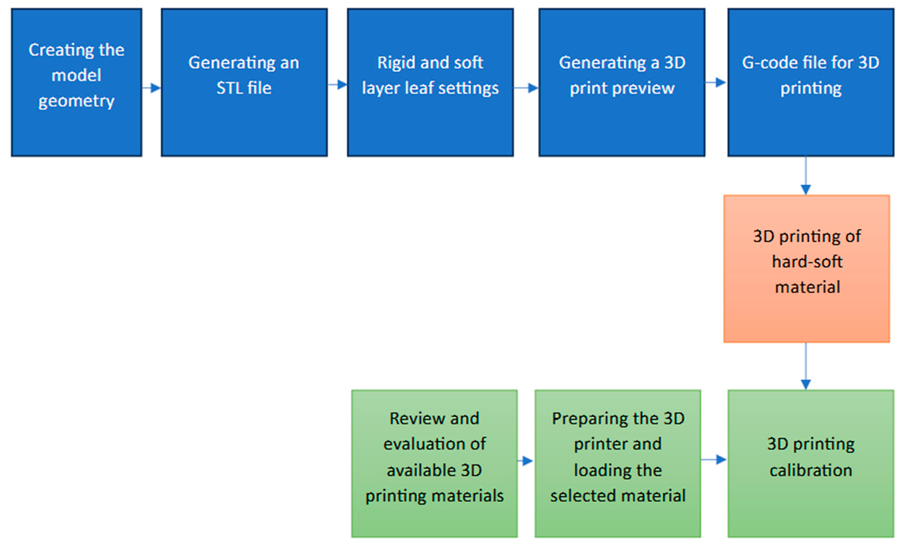
The study described in our article on the 3D-printed exoskeleton complies with the ISO/ASTM 52900:2021 [32] standard by utilizing material extrusion, a process category formally defined in the standard for thermoplastic polymer printing. This technique ensures consistent material behavior, layer adhesion, and dimensional accuracy, consistent with the standard’s emphasis on quality control and repeatability. Process parameters such as temperature, printing speed, and infill density were optimized and documented according to the terminology and classification systems defined in the ISO/ASTM 52900:2021 standard. Mechanical testing of the exoskeleton components was conducted according to post-production evaluation protocols to ensure that the parameters met the structural requirements specified in the standard. Our study follows the standard’s guidelines to confirm the reliability, safety, and manufacturability of the thermoplastic exoskeleton design and to ensure test replication (Figure 2).
The following project was undertaken:
  • Position of the bending element
    • Position parallel (from above) to the bent element;
    • Position perpendicular (lateral) to the bent element.
  • Location of the soft–rigid material connection.
    • The position of the bending element, i.e., where to locate the bending point.
For a rigid material, bending means irreversible changes in the material structure (crack). For a soft material, bending means reversible changes in the structure if it contains Young’s modulus for a given material, i.e., a linear deformation modulus or a modulus (coefficient) of longitudinal elasticity.
(a)
Position parallel (from above) to the bent element
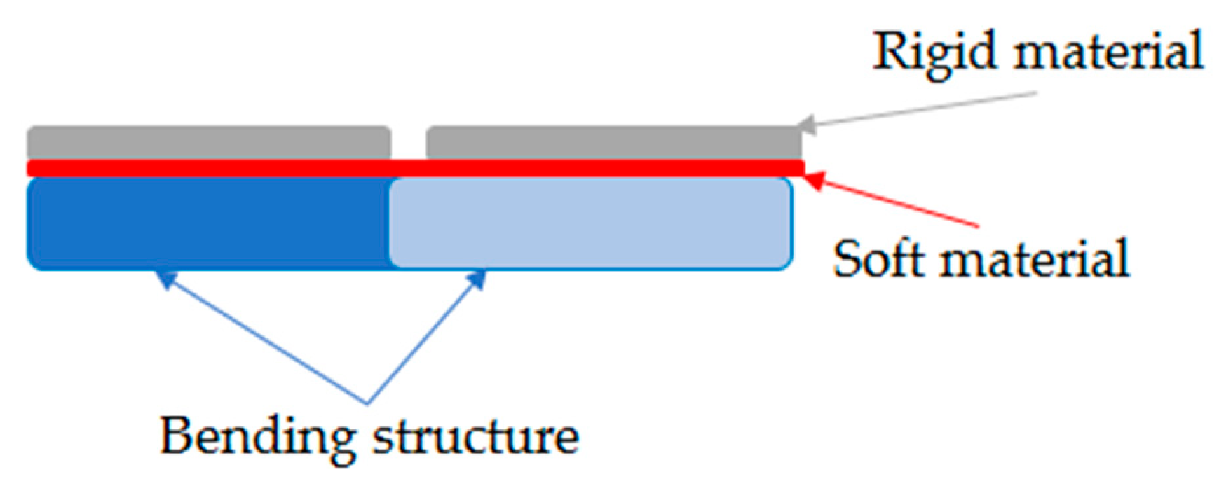
The element is located exactly of the bending element (exoskeleton) (Figure 3) on the bending structure (e.g., phalanges, human knee joint).Thanks to this, the movement of the bending element on the structure is reproduced one-to-one and there are no significant differences between the compressive and tensile stress for the soft material; for the rigid material, only minimal stresses occur (in this case mainly tensile stresses).
The element can be designed relatively quickly and easily using primitives (Boolean method of 3D objects) (Figure 4a,b).
(b)
Position perpendicular (lateral) to the bending element.
The element is positioned laterally (perpendicular) (Figure 5 and Figure 6) to the bending element. Here, problems with bulging appear (Figure 7a) during bending if we use the same shape (model) as in the parallel position.
Therefore, it was necessary to cut (Figure 7b) the material at the bending point and round it for better stress transfer.
  • Location of the soft–rigid material connection
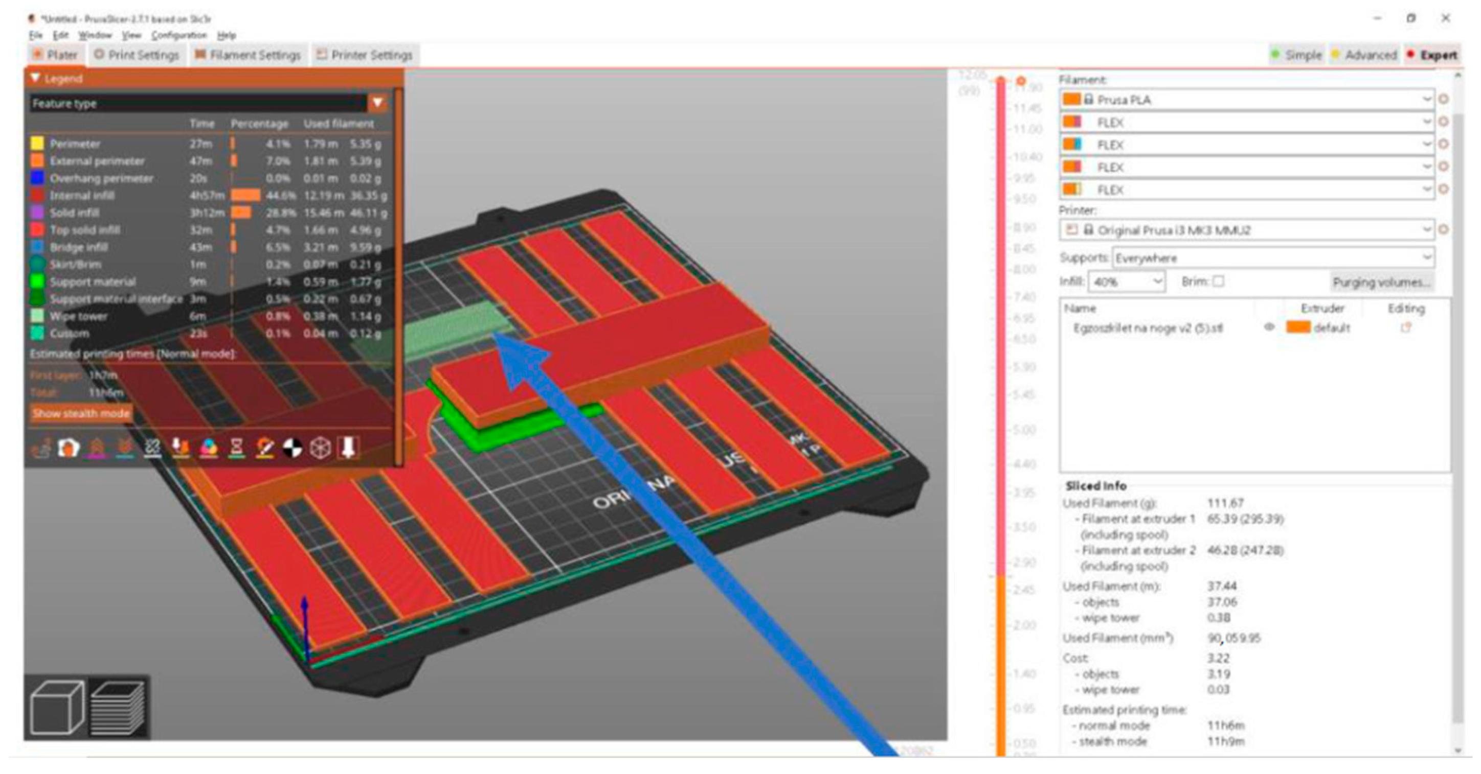
The location of the connection and which part consists of the rigid and soft material is important because the soft material is designed to provide user comfort, and, thanks to its mechanical properties, it serves as a flexible joint. We treat the soft material as the reinforcement (base) and the hard material as the matrix (external filling) (Figure 8).
We can therefore treat such a material as a composite according to the definition: the term composites means a material created by tightly combining at least two chemically different materials (phases: reinforcing and matrix) in such a way that despite a clear separation boundary between them, a good and continuous connection of the components occurs, and the reinforcing phase is as evenly distributed as possible in the matrix.
A fatigue testing method was used in this study, focusing on how many cycles the material could withstand. The test setup consisted of
  • A 400 kg · cm servo actuator;
  • A computer with control software;
  • A controller for operating the servo mechanism.
One cycle was defined as a full flexion movement from 0 degrees to 120 degrees.
As shown in Table 2, the fatigue resistance of the printed specimens depends strongly on the infill density and the infill pattern. For grid infill, increasing the density from 15% to 50% improved the cycle life from 32 to 42 cycles (approximately +31%). A similar effect was observed for gyroid infill, where cycle life increased from 29 to 49 cycles (+69%). Moreover, specimens with gyroid infill consistently achieved higher fatigue resistance than those with grid infill at comparable layer heights and densities (e.g., 50% gyroid–49 cycles vs. 50% grid–42 cycles). These findings demonstrate that both structural density and internal geometry directly influenced the ability of the hybrid interface to withstand cyclic loading, which confirms the experimental design conditions.

3. Results

3.1. Manufacturing—Material Selection

Thermal extrusion and polymer bonding were used, specifically 3D printing, which uses thermal bonding of the material. Bioflex and PLA were used because they have a common extraction (printing) temperature (Table 3).
The letters A and D on the Shore scale indicate different hardness ranges for different types of materials:
  • Shore A—scale for soft and flexible materials, such as rubber, silicone, or flexible filaments (e.g., TPU, Bioflex), e.g.,
    • 20A—very soft (gel shoe inserts);
    • 85A—flexible, but already noticeably hard (shopping cart tires);
    • 98A—almost stiff, but still a little flexible (e.g., sports shoe soles).
  • Shore D—scale for harder materials, such as hard rubber, plastics, or some composites (e.g., PLA, ABS), e.g.,
    • 50D—flexible plastic (soft phone case);
    • 70D—hard plastic (standard PLA, ABS);
    • 85D—very stiff plastic (e.g., polycarbonate, hard electronics casing).
The comparison of Shore A and Shore D shows that there is no exact conversion factor, but as a rough estimate, we can assume that Shore 98A ≈ Shore 50D, which is how the boundary between flexible and rigid material was drawn.

3.2. Manufacturing—Selection of Manufacturing Method

Three different methods were used to fabricate the hybrid soft–rigid interfaces:
  • Manual material change;
  • Automatic material change using wipe tower;
  • Tool change with multi-extruder system.
In the manual method, material change was performed by pausing the print and replacing the filament (Figure 9). While this approach required operator intervention, it proved to be the most material-efficient, with an average waste of only approx. 0.4 g per print. However, due to manual timing, inconsistencies were observed in layer bonding at the transition point, occasionally affecting interfacial adhesion in bending zones.
In the automatic method with wipe tower (e.g., Multimaterial Upgrade Prusa system), the printer handled filament changes independently (Figure 10). Although this method consumed more material due to the purge tower (1.14 g per print), it resulted in more consistent adhesion and smoother soft–rigid transitions, particularly in curved geometries. Mechanical performance during bending tests improved by 15% compared to the manual method (measured via interface fatigue resistance after 100 flexion cycles).
The multi-tool method, using a printer with up to five independent extruders (Figure 11), combined automation with lower purge waste (0.76 g). This setup produced the most precise material transitions and showed the highest mechanical durability in repeated load tests, with no visible delamination or deformation after 200 cycles. However, this method is the most expensive and least accessible for small labs or prototyping scenarios.
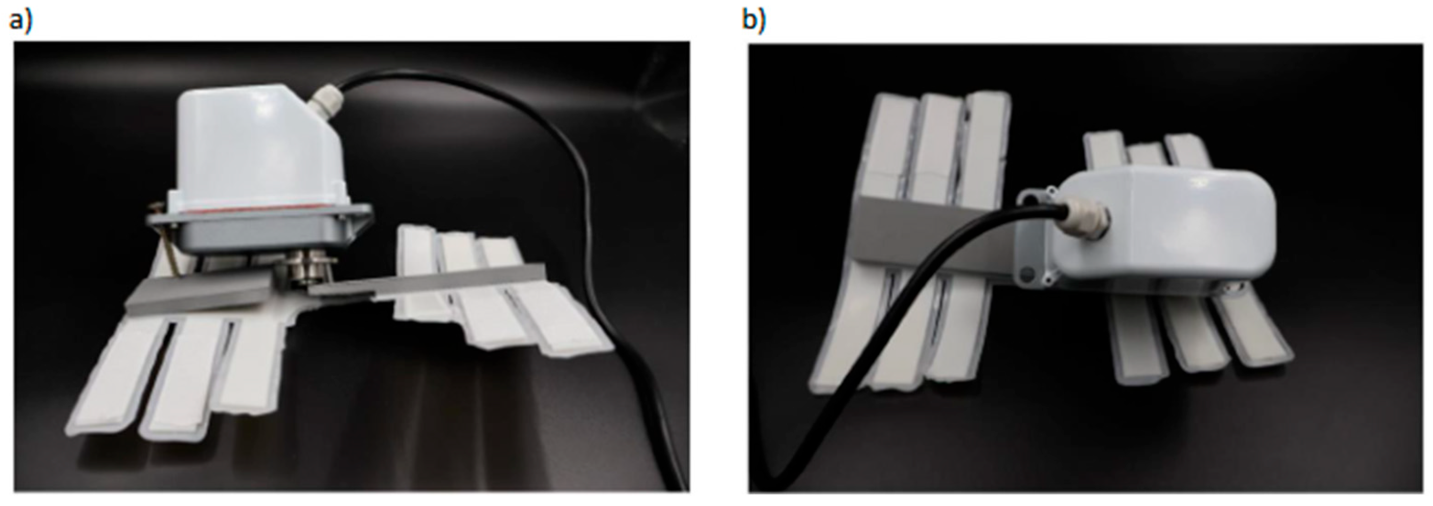
Figure 12 shows an example of a functional prototype (knee exoskeleton) printed via the multi-tool method, sustaining actuator torque of 400 kg·cm without structural failure.
Experience to date (Table 4, Figure 13 and Figure 14) has shown that there is no one-size-fits-all manufacturing method, but an example flowchart for creating soft and rigid interfaces in exoskeletons can be presented as follows:
  • Defining functional requirements: starting with defining user needs, range of motion (physiological in this specific case, including limitations), force output, and application (rehabilitation, care or strength reinforcement in case of weakness during recovery);
  • Material selection: appropriate soft materials (e.g., silicone, textiles) for comfort and flexibility and rigid components (e.g., plastic or even metal prints: aluminum, titanium, structural steel) for structure and force transfer;
  • Designing interface geometry: creating CAD models to optimize how soft and rigid parts connect around the anatomy, ensuring an ergonomic fit and unimpeded joint movement;
  • Simulating biomechanics: using software tools (e.g., motion analysis) to test stress distribution, motion fidelity, and potential pressure points on the skin;
  • Prototype/s: 3D printing, molding, or sewing for soft components, and CNC or additive manufacturing for rigid components;
  • Integration process: combining soft and rigid components using mechanical bonding, gluing, or interlocking structures to maintain flexibility where needed and rigidity where force is applied;
  • Adding actuators (if needed): incorporating actuators (e.g., tendons, pneumatic muscles, or motors) that work in harmony with the soft and rigid interface to provide smooth movement;
  • Embedding sensors (if needed): integrating sensors (such as force or position sensors) with the soft or rigid components for feedback and control;
  • User testing and adjustment: testing on users to assess fit, comfort, accuracy of movement, and safety, then refining the interface accordingly based on feedback;
  • Final assembly and evaluation: assemble the full exoskeleton, evaluate performance in real-world conditions, and document the design for future iterations;
  • Monitor usage, upgrades, and corrections.
Results of the fatigue test of soft–rigid interfaces in 3D-printed exoskeletons:
  • Specimen geometry and dimensions: 80 mm × 15 mm × 6 mm beam specimens with a central 20 mm soft segment bonded to rigid ends;
  • Material composition: TPU (Shore 85A) soft segment, PLA rigid segments, joined using direct multimaterial printing with an overlap bonding zone;
  • Loading mode: 3-point bending cyclic test;
  • Cycle frequency: 2 Hz;
  • Load amplitude and range: 10–40 N per cycle;
  • Stress ratio: 0.25;
  • Environmental conditions: 25 °C, 50% relative humidity;
  • Number of cycles to failure in mass testing: average of 48,500 cycles before visible crack initiation in the soft–rigid transition zone;
  • Displacement/strain measurement method in mass testing: digital image correlation revealed a progressive strain concentration shift toward the bonding overlap after approx. 35,000 cycles;
  • Failure criteria: stiffness reduction by 20% and visible delamination between TPU and PLA; average stiffness drop observed in mass testing at 46,800 cycles.
In light of the experience to date, the main challenges in creating low-cost and simple 3D-printed soft and rigid interfaces for exoskeletons are as follows:
  • Achieving a balance between flexibility and support is difficult because soft materials must allow for natural movement, while rigid parts must effectively transfer force without causing discomfort;
  • Comfort and fit are difficult because human hands vary greatly in size and shape, making it difficult to design interfaces that are both universal and ergonomic;
  • Attachment and connection techniques between soft and rigid components often fail under repeated stress or movement, leading to delamination or mechanical damage;
  • Durability over time is an issue because soft materials can wear out or deform during use, compromising performance and requiring frequent replacement;
  • Skin safety and pressure distribution must be carefully managed to avoid pressure sores, abrasions, or circulation problems during long-term use;
  • Precision in motion transmission can be lost due to deformation of soft materials, making it difficult to maintain precise finger or movements;
  • Integrating sensors and actuators into a hybrid structure is technically complex because it is difficult to route electronics through flexible and rigid zones without damage;
  • Manufacturing complexity increases when combining materials with different mechanical properties, requiring custom manufacturing techniques and tooling;
  • Cost and scalability become an issue when producing these interfaces for widespread clinical or commercial use due to the complexity of hybrid systems;
  • Hygiene and maintenance are challenging because soft materials more easily absorb sweat or dirt and are harder to clean without compromising the structure (Figure 15).
It is worth noting that the challenge is not only related to design issues but also to maintenance, as long-term use of the exoskeleton imposes significant requirements in terms of durability and movement repeatability.
As of today, the main technological principles in creating 3D-printed soft–rigid interfaces for exoskeletons seem to be the following:
  • Material compatibility is essential; thermoplastics (such as TPU for soft parts and PLA or ABS for rigid parts) that can combine well in multimaterial 3D printing must be selected;
  • Interface design geometry must provide smooth transitions with fillets or stepped structures to reduce stress concentration at the soft–rigid interface;
  • Printer capabilities should support dual-material or multimaterial printing, with precise temperature and flow control to avoid poor layer adhesion;
  • Orientation and layering strategy affect strength and flexibility: rigid parts must align with load paths, while soft parts should follow curves for better compliance;
  • Post-production may be needed to reinforce joints or add coatings to ensure the durability and safety of the skin, especially where different materials come into contact;
  • Iterative testing is critical because mechanical performance and comfort must be verified through real-world simulations and user feedback to refine print and design parameters.

4. Discussion

The in-house results (up to 48,500 cycles in mass testing) exceed those of existing PLA-only components, which can withstand only a few thousand cycles, which may not be sufficient for everyday exoskeletons. FDM process modifications, such as those used in exoskeletons, further improve fatigue resistance compared to standard prints, although without significantly increasing the number of cycles. Bioinspired design strategies (smooth gradients and interlocking geometries) offer up to 50% better strength, resulting in even longer fatigue life compared to simpler designs. Composite test frames often extend to ~106 cycles, indicating that the proposed setup can be extended to explore even higher cyclic life. Advanced structural optimization methods, such as random thickness variation, have the potential to further delay initial failure, increasing fatigue life.
The results demonstrate significantly better fatigue resistance than unmodified PLA and promising toughness compared to other soft–stiff interfaces. To meet or exceed the highest demands of composite fatigue testing, often reaching six-digit cycle counts, future work could incorporate gradient geometry designs, stepped interconnects, and advanced printing strategies. These improvements could further enhance the durability and reliability of soft–stiff interfaces in exoskeleton applications.
Integrating soft and rigid components in robotic exoskeletons mirrors biological principles, combining stiffness for load-bearing and flexibility for movement adaptation. While this concept has been widely accepted in prior research, practical implementation challenges remain, such as ensuring robust adhesion, preventing fatigue at material transitions, and maintaining performance over time [6].
Our study builds on these foundations by comparing three accessible FDM-based fabrication techniques for soft–rigid interfaces, evaluating their impact on mechanical performance and functional usability. Unlike earlier studies that focus primarily on novel geometries or high-end printers [13,18], we emphasize cost-effective methods suitable for clinical and prototyping contexts. In particular, we quantified shear and peel resistance in bonded zones, showing that hybrid designs with geometric interlocking structures and tailored print orientation improved durability under cyclic loading.
A paper on soft–rigid interfaces in 3D-printed exoskeletons presents experimental data demonstrating how integrating compliant and stiff segments improves both flexibility and load-bearing capacity. Tests demonstrated that the soft and stiff interfaces allow for local bending without compromising overall structural integrity, distributing stress more evenly throughout the frame. High-resolution strain measurements revealed that bending initiates in the soft zones, which act as hinges, while the stiff segments maintain shape stability under load. This hybrid architecture mimics, among other things, biological exoskeletons, where flexible joints and stiff plates work together to optimize movement and protection. The obtained results provide both empirical support and a mechanical explanation for the bending processes observed in such interwoven structures, highlighting their potential in wearable robotics and assistive devices.
One promising approach involves under extrusion techniques, creating porous, connective, tissue-like layers that improve bonding and reduce reliance on adhesives. This technique reached up to 200% of the shear strength achieved by standard adhesive bonding in our tests, confirming findings by other authors [6].
Soft–rigid interfaces are also critical in human–robot interaction due to their compliance and safety, but they introduce their own engineering trade-offs:
  • Limited strength at transition zones;
  • Complex geometries;
  • Increased wear.
To address these, recent studies explore bioinspired surface geometries, such as lobster shell patterns or wave-like transitions [13,19], that distribute stress and improve mechanical interlock. Nevertheless, fabrication complexity and scale limitations remain obstacles to widespread adoption.
Future applications of soft–rigid systems extend into
  • Telehealth;
  • Immersive rehabilitation;
  • Wearable diagnostics.
In these cases, realistic haptic interfaces are needed. However, current commercial 3D printing solutions often result in overly rigid or bulky devices, limiting integration with the human body [18].
The use of AI-assisted CAD modeling and 3D scanning enables the precise design of soft and rigid interfaces in 3D-printed exoskeletons, optimizing geometry for comfort and performance. During the fitting process, AI algorithms analyze biomechanical data from motion-capturing and wearable sensors to tailor joint flexibility and stiffness to each user’s anatomy. During the printing stage, AI-based process control adjusts printing parameters in real time to ensure strong adhesion at the interfaces between soft and rigid components and minimize the risk of defects. During operation, embedded AI systems process sensor feedback to adjust the exoskeleton’s responses, fine-tuning support and movement performance based on the user’s evolving needs. During the recycling stage, AI-based material classification systems identify and separate soft and rigid components, enabling more efficient reuse and reducing environmental impact.
By proposing validated, reproducible, and material-efficient solutions, our work contributes to advancing practical integration of soft–rigid interfaces in wearable assistive robotics.
Previous research has shown that just as natural biological solutions use a combination of stiffness for structural support and softness for adaptation, integrating stiffness and softness into a design can increase the versatility of soft robotics. However, material and design challenges associated with creating simple, durable, and functional interfaces between soft and rigid materials are still limiting the rapid development of hybrid robots such as exoskeletons. To avoid the use of expensive specialized machines (e.g., Polyjet 3D printers), research is underway on less expensive 3D printing techniques that work with commercially available FDM printers to utilize underextrusion to create a connection between soft and rigid materials. The porous, connective tissue-like structure provides a solid connection to the rigid part by bonding layers, achieving almost 200% strength in lap shear and peel tests and three times the pressure of current adhesive solutions [31]. A methodology for designing soft and rigid grippers for performing various manipulation tasks has also been developed thanks to wave-shaped hinges with predesigned geometric parameters and different three-dimensional resistance characteristics. This allows, for example, for gripping objects with adaptations to their shapes and dimensions or for manipulating objects [33]. Soft–rigid interfaces solve safety problems in physical human–robot interactions, but they pose their own challenges in design, manufacturing, and analysis and are prone to damage due to the softness of their material, hence the attempts to improve them by applying hybrid solutions with bioinspired crustacean motifs (e.g., mimicking the pattern of the lobster abdomen shell) [34]. Soft–rigid interfaces are critical for many robotic systems and applications, including grasping and manipulating objects. Many solutions have been inspired by the dexterity and functionality of biological patterns, including the grasping human hand. However, these patterns are often too complex to design, control, and perceive. Hence, morphological deformation or adhesion mechanisms are becoming increasingly popular, for example, simplifying grasping without detailed knowledge of the geometry of the grasped object. This facilitates the use of robots in Industry 4.0/5.0 and eHealth at lower costs and complexity. Soft, non-anthropomorphic methods of cooperation for soft–rigid interfaces are promising [35]. Greater emphasis on telemedicine and telehealth, medical education and training, healthcare supply chains, and fitness and wellness (including within the Metaverse) may bring further applications of 3D-printed soft–rigid interfaces as they become more realistic and more reflective of real environments and biological objects [36,37]. Immersive treatment and physical therapy have the potential to affect many disciplines, but current 3D-printed aids suffer from stiffness and a cumbersome form factor that is incompatible with the flexible limbs of the human body and their dynamic movements [15]. For these reasons, advances in soft material technology and 3D-printed soft–rigid interfaces are uniquely suited to provide a low-cost and rapid solution to this challenge. Hence, there is an increasing emphasis in the research literature on developing devices made of flexible and elastic biocompatible materials that better conform to the human body, thus leading to a more natural user experience of devices such as exoskeletons.
Three available FDM-based manufacturing techniques for creating soft and stiff interfaces in 3D-printed exoskeletons are direct multimaterial printing, mechanical interlocking geometry, and gradient transitions. Direct multimaterial printing uses two extruders or filament switching systems to deposit soft and stiff polymers in a single process, creating seamless connections but requiring precise calibration to avoid poor adhesion at the interface. Mechanical interlocking geometry designs—such as dovetail joints, teeth, or puzzle pieces—physically join materials, improving load transfer and fatigue resistance without relying solely on chemical adhesion. Gradient transitions gradually change stiffness, blending soft and stiff zones through patterned changes in infill density, reducing stress concentrations and enabling smoother bending. In practice, multimaterial printing offers the cleanest integration, the connections provide solid mechanical anchoring, and the gradient transitions provide the best stress distribution, which translates into long-term durability.
Increasing the infill density of a 3D-printed exoskeleton to 60% generally improves its mechanical strength and stiffness. This higher density means there is more material to absorb and loads to distribute, which can reduce local stresses and delay the onset of material fatigue. As a result, the exoskeleton is likely to withstand a greater number of loading cycles before failure. The increased support structure also contributes to improved dimensional stability during repeated use. However, the added material increases the component’s weight, which can introduce new stress factors depending on the application. Furthermore, denser prints can accumulate more internal stresses during printing, which can negatively impact fatigue life if not managed properly. A 60% infill typically improves fatigue resistance and cycle life, but the ultimate impact depends on the design, material type, and loading conditions.
Raising Bioflex’s printing temperature to 240 °C can improve its bond strength with PLA by improving interlayer adhesion. At higher temperatures, becomes more fluid, allowing it to bond better to the PLA surface during extrusion. This improved bonding can lead to a stronger mechanical bond between the two materials. However, exceeding the recommended temperature range for Bioflex can cause degradation, resulting in poor print quality or weakening the material’s properties. Therefore, while a temperature of 240 °C may improve bonding, it should always be thoroughly tested to ensure it does not compromise the integrity of the Bioflex.
Changing the interface between soft and stiff materials to a stepped transition in a 3D-printed exoskeleton can significantly reduce stress concentrations. The stepped transition distributes mechanical loads more gradually between materials of varying stiffness, rather than abruptly shifting stresses at a sharp interface. This design can reduce peak stresses at the interface by 30–70%, depending on the geometry and material properties. By minimizing sudden stress differences, the risk of delamination or cracking at the interface is also reduced.
Extending the dwell time during manual material changes in 3D printing can weaken the interlayer bond strength in the printed exoskeleton. As the previously deposited layer cools during the extended dwell time, the potential for thermosetting with the subsequent layer decreases. This temperature drop can lead to poor interlayer adhesion, creating weak spots at the material interface. These weak bonds can reduce the mechanical strength and durability of the exoskeleton under load. To maintain optimal interlayer bonding, we minimize the dwell time or reheat the print bed before resuming printing.
Adding a small amount of carbon fiber to a soft material can improve its fatigue resistance by reinforcing the polymer matrix. Carbon fibers help distribute stress evenly and prevent the formation and growth of microcracks under repeated loading. This reinforcement reduces strain localization, a common cause of fatigue failure in soft materials. However, excessive fiber content can reduce elasticity, potentially leading to brittleness and premature failure under dynamic loading. Therefore, when properly balanced, a small addition of carbon fiber can improve fatigue resistance without sacrificing the material’s elasticity.

4.1. Limitations

Soft–rigid interfaces in exoskeletons often struggle to effectively transfer forces due to differences in stiffness between the soft and rigid components [36]. Rigid components can cause pressure points or discomfort when contacting the soft human, limiting user comfort and extending wearability [37]. Repetitive movements of soft materials against rigid structures can lead to wear, reducing the overall life of the exoskeleton [38]. The flexibility of soft materials can cause unintended deformation, reducing the accuracy and control of forces applied to the fingers [39]. Uneven weight distribution between soft and rigid components can cause balance issues, affecting ease of use and natural movements [40]. Providing a secure and stable connection between rigid and soft components is difficult, which can lead to slippage or misalignment during operation [41]. Manufacturing and assembly of these hybrid systems requires specialized techniques to seamlessly integrate soft and rigid parts, which increases the difficulty and cost of production [42]. Soft materials can absorb sweat and dirt, making cleaning and maintenance more difficult compared to fully rigid exoskeletons [43]. Energy loss can occur at the interface due to the compliance of soft materials, which reduces the efficiency of force transfer from the actuators to the exoskeleton [44,45]. Achieving a universal design is difficult because differences in hand size and shape require adaptive interfaces that provide both comfort and functionality [46,47].

4.2. Directions of Further Research

Research should focus on developing hybrid materials that optimize the mechanical properties of soft and rigid components to increase durability, flexibility, and comfort [48,49]. Future research should explore bio-inspired and adaptive designs that improve the fit and interaction between the exoskeleton and the human anatomy [50]. Exploring advanced connection and assembly techniques, such as 3D printing or soft robotics-inspired manufacturing, can improve the interface between soft and rigid components [51]. Research should explore incorporating smart materials, such as shape memory alloys or variable stiffness structures, to dynamically adjust stiffness based on user needs [52]. Developing better sensor integration into the soft and rigid interface will improve haptic feedback, proprioception and user control [53]. Research should focus on long-term usability, ensuring that exoskeletons remain comfortable, breathable, and non-restrictive during long-term wear [54]. Research should optimize the force transmission mechanisms to minimize energy loss across the soft and rigid interface, improving the overall performance of the exoskeleton [55,56]. The implementation of AI-based or automated customization techniques, such as 3D scanning and digital modeling, can help create better-fitting exoskeletons for different users [57,58]. The development of self-healing or easy-to-clean materials for soft and rigid interfaces can increase the durability and practicality of exoskeletons [59]. Further research should focus on the medical and therapeutic potential of soft and rigid exoskeletons, ensuring that they provide effective assistance to people with disabilities or injuries [60,61,62,63].
Future research may also benefit from the integration of AI methods alongside material and structural analyses. AI-based approaches could support advanced process monitoring and predictive modeling of material behavior, thereby complementing experimental investigations.

5. Conclusions

Soft–rigid interfaces significantly improve user comfort in wearable exoskeletons. Soft segments provide compliance and cushioning at contact points (e.g., shoulders, back, joints), reducing pressure sores or abrasions that are more common in rigid-only systems. Soft–rigid integration allows exoskeletons to better conform to the human body, facilitating long-term wear and user compliance.
Soft–rigid hybrid interfaces enable controlled deformation, helping to more evenly distribute mechanical loads. This minimizes stress concentrations at the interfaces between soft and rigid parts, improving durability and functionality. Properly designed soft–rigid interfaces increase mechanical resistance and help prevent failures at material transition zones.
Advances in multimaterial 3D printing (e.g., PolyJet, dual extrusion FDM) enable the direct manufacturing of monolithic structures connecting hard and soft areas. This reduces the need for manual assembly, adhesives, or fasteners. The 3D printing of soft–rigid interfaces simplifies manufacturing and enables complex geometries and functional gradations that are difficult to achieve with traditional manufacturing.
Despite their advantages, soft–rigid interfaces often suffer from delamination, poor adhesion, or fatigue under cyclic loading. Material compatibility and interfacial bond strength remain key areas of research. While promising, soft–rigid interfaces require careful material selection and interface engineering (e.g., interlocking structures or gradient transitions) to ensure long-term reliability.
Three-dimensional printing enables customization to individual users, optimizing both support and mobility. Custom exoskeletons can integrate soft–rigid components exactly where needed, based on body scans or biomechanical data. Soft–rigid interfaces open up the possibility of highly personalized exoskeletons optimized for both biomechanics and user-specific anatomy.

Author Contributions

Conceptualization, I.R., J.K., M.A. and D.M.; methodology, I.R., J.K., M.A. and D.M.; software, I.R., J.K., M.A. and D.M.; validation, I.R., J.K., M.A. and D.M.; formal analysis, I.R., J.K., M.A. and D.M.; investigation, I.R., J.K., M.A. and D.M.; resources, I.R., J.K., M.A. and D.M.; data curation, I.R., J.K., M.A. and D.M.; writing—original draft preparation, I.R., J.K., M.A. and D.M.; writing—review and editing, I.R., J.K., M.A. and D.M.; visualization, I.R., J.K., M.A. and D.M.; supervision, I.R.; project administration, I.R.; funding acquisition, I.R. All authors have read and agreed to the published version of the manuscript.

Funding

The work presented in this paper has been financed via a grant to maintain the research potential of Kazimierz Wielki University in Bydgoszcz.

Data Availability Statement

The original contributions presented in this study are included in the article. Further inquiries can be directed to the corresponding author.

Conflicts of Interest

The authors declare no conflicts of interest.

Abbreviations

The following abbreviations are used in this manuscript:
3DTree-dimensional
ABSAcrylonitrile butadiene styrene
AIArtificial intelligence
DIWDirect ink writing
DLPDigital light processing
FGMFunctionally gradient materials
FDMFused deposition modeling
MLMachine learning
TPUThermoplastic polyurethane

References

  1. Schmitt, F.; Piccin, O.; Barbe, L. Soft Robots Manufacturing: A Review. Front. Robot. AI 2018, 5, 84. [Google Scholar] [CrossRef]
  2. Alici, G. Softer is Harder: What Differentiates Soft Robotics from Hard Robotics? MRS Adv. 2018, 3, 1557–1568. [Google Scholar] [CrossRef]
  3. Li, L.; Crosby, D.; Shuttleworth, M.; Argin, O.F.; Chen, A.S.; Herrmann, G.; Kay, R.; Weightman, A. A Comparative Analysis and Scoping Review of Soft–Rigid and Industrial Parallel Rigid Grippers. Adv. Intell. Syst. 2024, 7, 2400503. [Google Scholar] [CrossRef]
  4. Rojek, I.; Mikołajewski, D.; Dostatni, E.; Kopowski, J. Specificity of 3D Printing and AI-Based Optimization of Medical Devices Using the Example of a Group of Exoskeletons. Appl. Sci. 2023, 13, 1060. [Google Scholar] [CrossRef]
  5. Logozzo, S.; Valigi, M.C. A Gripper with Wave Joint Fingers for Precision Grasping. In Proceedings of the International Conference of IFToMM ITALY 2024, Torino, Italy, 11–13 September 2024; Springer Nature: Cham, Switzerland, 2024; pp. 492–499. [Google Scholar]
  6. Blanco, K.; Navas, E.; Rodríguez-Nieto, D.; Emmi, L.; Fernández, R. Design and Experimental Assessment of 3D-Printed Soft Grasping Interfaces for Robotic Harvesting. Agronomy 2025, 15, 804. [Google Scholar] [CrossRef]
  7. Yap, Y.L.; Sing, S.L.; Yeong, W.Y. A review of 3D printing processes and materials for soft robotics. Rapid Prototyp. J. 2020, 26, 1345–1361. [Google Scholar] [CrossRef]
  8. Kusuhara, R.; Higashimori, M. Task-Oriented Design Method for Monolithic Flexible Hands with Wire Drive Systems. In Proceedings of the 2024 IEEE/RSJ International Conference on Intelligent Robots and Systems (IROS), Abu Dhabi, United Arab Emirates, 14–18 October 2024; pp. 3022–3029. [Google Scholar]
  9. Cui, Y.; An, X.; Lin, Z.; Guo, Z.; Liu, X.J.; Zhao, H. Design and implementation of an underactuated gripper with enhanced shape adaptability and lateral stiffness through semi-active multi-degree-of-freedom endoskeletons. Int. J. Robot. Res. 2024, 43, 873–896. [Google Scholar] [CrossRef]
  10. Dragusanu, M.; Troisi, D.; Prattichizzo, D.; Malvezzi, M. Joint Stiffness Analysis and Regulation for Underactuated Soft Grippers Based on Monolithic Structure. In Proceedings of the International Workshop IFToMM for Sustainable Development Goals, Bilbao, Spain, 22–23 June 2023; Springer Nature: Cham, Switzerland, 2023; pp. 492–499. [Google Scholar]
  11. Kim, J.; Cho, J.; Kang, Y.; Lee, C.; Yun, D. Development of a Modular Robotic Finger for Gripping Various Shaped Objects. In Proceedings of the 2024 IEEE/RSJ International Conference on Intelligent Robots and Systems (IROS), Abu Dhabi, United Arab Emirates, 14–18 October 2024; pp. 5226–5231. [Google Scholar]
  12. Azad, M.T.; Hossain, M.F.; Rahman, S.; Shidujaman, M.; Xue, M. Developing Prosthetic Hand: Innovation in Hand Movement for Paralyzed Individuals. In Proceedings of the International Conference on Human-Computer Interaction, Washington, DC, USA, 29 June–4 July 2024; Springer Nature: Cham, Switzerland, 2024; pp. 163–176. [Google Scholar]
  13. AboZaid, Y.A.; Aboelrayat, M.T.; Fahim, I.S.; Radwan, A.G. Soft robotic grippers: A review on technologies, materials, and applications. Sens. Actuators A Phys. 2024, 372, 115380. [Google Scholar] [CrossRef]
  14. Le, H.G.; Ho, N.L.; Dao, T.P. Design synthesis, modeling, control strategies, and fabrication methods of compliant grippers for micromanipulation and micromanipulator: A comprehensive review. Robot. Comput.-Integr. Manuf. 2025, 92, 102893. [Google Scholar] [CrossRef]
  15. Wang, X.; Lin, A.; Yuan, W.; Hu, H.; Cheng, G.; Ding, J. Design of an actuator with bionic claw hook—Suction cup hybrid structure for soft robot. Bioinspiration Biomim. 2024, 19, 036021. [Google Scholar] [CrossRef]
  16. Goh, G.L.; Huang, X.; Toh, W.; Li, Z.; Lee, S.; Yeong, W.Y.; Ng, T.Y. Joint angle prediction for a cable-driven gripper with variable joint stiffness through numerical modeling and machine learning. Int. J. AI Mater. Des. 2024, 1, 2328. [Google Scholar] [CrossRef]
  17. Wang, X.; Zhang, T.; Yu, H.; Wen, Z.; Fang, L.; Liu, H.; Sun, F.; Tang, L.; Fang, B. Bionic Soft Fingers with Hybrid Variable Stiffness Mechanisms for Multimode Grasping. In Proceedings of the 2024 IEEE International Conference on Robotics and Automation (ICRA), Yokohama, Japan, 13–17 May 2024; pp. 1957–1963. [Google Scholar]
  18. Then Mozhi, G.; Dhanalakshmi, K.; Choi, S.B. Design and control of monolithic compliant gripper using shape memory alloy wires. Sensors 2023, 23, 2052. [Google Scholar] [CrossRef] [PubMed]
  19. Rojek, I.; Macko, M.; Mikołajewski, D.; Saga, M.; Burczynski, T. Modern methods in the field of machine modeling and simulation as a research and practical issue related to Industry 4.0. Bull. Pol. Acad. Sci. Tech. Sci. 2021, 69, e136719. [Google Scholar] [CrossRef]
  20. Dragusanu, M.; Troisi, D.; Prattichizzo, D.; Malvezzi, M. Compliant Finger Joint with Controlled Variable Stiffness based on Twisted Strings Actuation. In Proceedings of the 2023 IEEE International Conference on Robotics and Automation (ICRA), London, UK, 29 May–2 June 2023; pp. 7378–7384. [Google Scholar]
  21. Troisi, D.; Dragusanu, M.; Villani, A.; Prattichizzo, D.; Malvezzi, M. Hapticpalm: A wearable robotic device for haptics and rehabilitative hand treatments. In Proceedings of the International Conference on Social Robotics, Florence, Italy, 13–16 December 2022; Springer Nature: Cham, Switzerland, 2022; pp. 402–411. [Google Scholar]
  22. Mikołajewski, D.; Rojek, I.; Kotlarz, P.; Dorożyński, J.; Kopowski, J. Personalization of the 3D-Printed Upper Limb Exoskeleton Design—Mechanical and IT Aspects. Appl. Sci. 2023, 13, 7236. [Google Scholar] [CrossRef]
  23. Achilli, G.M.; Logozzo, S.; Valigi, M.C.; Dragusanu, M.; Malvezzi, M. Theoretical and experimental characterization of a own robotic gripper’s joint. In Proceedings of the International Conference of IFToMM ITALY, Naples, Italy, 7–9 September 2022; Springer International Publishing: Cham, Switzerland, 2022; pp. 738–745. [Google Scholar]
  24. Chen, H.; Zhu, J.; Cao, Y.; Xia, Z.; Chai, Z.; Ding, H.; Wu, Z. Soft-rigid coupling grippers: Collaboration strategies and integrated fabrication methods. Sci. China Technol. Sci. 2023, 66, 3051–3069. [Google Scholar] [CrossRef]
  25. Rojek, I.; Kaczmarek, M.; Kotlarz, P.; Kempiński, M.; Mikołajewski, D.; Szczepański, Z.; Kopowski, J.; Nowak, J.; Macko, M.; Szczepańczyk, A.; et al. Hand Exoskeleton—Development of Own Concept. Appl. Sci. 2023, 13, 3238. [Google Scholar] [CrossRef]
  26. Available online: https://wyss.harvard.edu/owns/low-cost-wearables-manufactured-by-hybrid-3d-printing/ (accessed on 21 April 2025).
  27. Available online: https://srl.ethz.ch/the-group/people/Ronan-Hinchet.html (accessed on 21 April 2025).
  28. Available online: https://news.mit.edu/2022/materials-sense-movements-0810 (accessed on 21 April 2025).
  29. Goshtasbi, A.; Grignaffini, L.; Sadeghi, A. From Problem to Solution: Bio-inspired 3D Printing for Bonding Soft and Rigid Materials via Underextrusions. Sci. Rep. 2024, 15, 4429. [Google Scholar]
  30. Dragusanu, M.; Achilli, G.M.; Valigi, M.C.; Prattichizzo, D.; Malvezzi, M.; Salvietti, G. The Wavejoints: A Novel Methodology to Design Soft-Rigid Grippers Made by Monolithic 3D Printed Fingers with Adjustable Joint Stiffness. In Proceeding of the International Conference on Robotics and Automation (ICRA), Philadelphia, PA, USA, 23–27 May 2022; pp. 6173–6179. [Google Scholar]
  31. Chen, Y.; Le, S. A Lobster-Inspired Hybrid Actuator with Rigid and Soft Components. In Proceedings of the 41st Mechanisms and Robotics Conference, Cleveland, OH, USA, 6–9 August 2017; Volume 5B. [Google Scholar]
  32. ISO/ASTM 52900:2021; Additive Manufacturing—General Principles—Fundamentals and Vocabulary. 2nd ed. International Organization for Standardization: Geneva, Switzerland, 2021. Available online: https://www.iso.org/standard/74514.html (accessed on 18 August 2025).
  33. Park, J.; Lee, Y.; Cho, S.; Choe, A.; Yeom, J.; Ro, Y.G.; Kim, J.; Kang, D.H.; Lee, S.; Ko, H. Soft sensors and actuators for wearable human–machine interfaces. Chem. Rev. 2024, 124, 1464–1534. [Google Scholar] [CrossRef]
  34. Musamih, A.; Yaqoob, I.; Salah, K.; Jayaraman, R.; Al-Hammadi, Y.; Omar, M.; Ellahham, S. Metaverse in healthcare: Applications, challenges, and future directions. IEEE Consum. Electron. Mag. 2022, 12, 33–46. [Google Scholar] [CrossRef]
  35. Yin, J.; Hinchet, R.; Shea, H.; Majidi, C. Wearable soft technologies for haptic sensing and feedback. Adv. Funct. Mater. 2021, 31, 2007428. [Google Scholar] [CrossRef]
  36. Nguyen, V.P.; Dhyan, S.B.; Mai, V.; Han, B.S.; Chow, W.T. Bioinspiration and biomimetic art in robotic grippers. Micromachines 2023, 14, 1772. [Google Scholar] [CrossRef]
  37. Zhao, J.; Xia, N.; Zhang, L. A review of bioinspired dry adhesives: From achieving strong adhesion to realizing switchable adhesion. Bioinspiration Biomim. 2024, 19, 051003. [Google Scholar] [CrossRef]
  38. Keely, M.; Kim, Y.; Mehta, S.A.; Hoegerman, J.; Ramirez Sanchez, R.; Paul, E.; Mills, C.; Losey, D.P.; Bartlett, M.D. Combining and decoupling rigid and soft grippers to enhance robotic manipulation. Soft Robot. 2025. [Google Scholar] [CrossRef] [PubMed]
  39. Jiang, C.; Wang, D.; Cheng, P.; Qiu, L.; Li, C. Design and optimization of a novel multi layer conical Kresling origami mechanism (MCKOM) for linear actuation. Mech. Mach. Theory 2024, 203, 105796. [Google Scholar] [CrossRef]
  40. Mehta, G.D.; Shelare, S.D.; Pachpor, A.A.; Sharma, S.; Kumar, R.; Bisht, Y.S.; Kumar, S.; Abbas, M. Unravelling the dynamics of misalignment-induced vibrations in two jaw elastomeric couplings for enhanced industrial reliability: A comprehensive analysis of dynamics and diagnostic approaches. J. Vib. Eng. Technol. 2024, 12, 413–426. [Google Scholar] [CrossRef]
  41. Hu, T.; Lu, X.; Yi, J.; Wang, Y.; Xu, D. Biomimetic soft robotic wrist with 3-DOF motion and stiffness tunability based on ring-reinforced pneumatic actuators and a particle jamming joint. Sci. China Technol. Sci. 2024, 67, 774–790. [Google Scholar] [CrossRef]
  42. Gai, L.J.; Huang, J.; Zhang, Y.; Zong, X.; Ding, H. A soft finger with tensile variable stiffness based on the cross-sliding jamming mechanism. IEEE Robot. Autom. Lett. 2024, 9, 3427–3434. [Google Scholar] [CrossRef]
  43. Zhen, R.; Jiang, L.; Ding, K.; Li, H. Force Perception for Rigid-Soft Finger Without Force Sensors: Theoretical Analysis, and Model Transfer. IEEE Robot. Autom. Lett. 2023, 9, 1867–1874. [Google Scholar] [CrossRef]
  44. Jian, H.E.; Wang, Y.; Tang, H.; Zhang, G.; Dong, K.; Wang, D.; Xia, L.; Xiong, Y. Customizable bistable units for soft-rigid grippers enable handling of multi-feature objects via data-driven design. Mater. Horiz. 2025, 12, 4426–4433. [Google Scholar]
  45. Troisi, D.; Dragusanu, M.; Pozzi, M.; Prattichizzo, D.; Malvezzi, M. A Soft-Rigid Gripper for Safe Handling and Transportation. Adv. Mater. Technol. 2024, 10, 2401592. [Google Scholar] [CrossRef]
  46. Chung, Y.C.; Chow, W.T.; Nguyen, V.P. Soft robotic honeycomb-velcro jamming gripper design. Actuators 2024, 13, 359. [Google Scholar] [CrossRef]
  47. Kargar, S.M.; Berselli, G. Tricom gripper—Parti ii: Soft pad integration and virtual prototyping for delicate object handling. In Proceedings of the 2024 20th IEEE/ASME International Conference on Mechatronic and Embedded Systems and Applications (MESA), Genova, Italy, 2–4 September 2024; pp. 1–6. [Google Scholar]
  48. Allison, K.; Kelly, J.; Hatton, B. Structured Pneumatic Fingerpads for Actively Tunable Grip Friction. arXiv 2025, arXiv:2502.00926. [Google Scholar]
  49. Keely, M.N. Using Rigid and Soft Grippers for Assistive Robotic Tasks. Ph.D. Thesis, Virginia Tech, Blacksburg, VA, USA, 2025. [Google Scholar]
  50. Wu, P.; Lan, F.; Hong, W.; Chen, X.; Shuai, W.; Cui, G.; Gao, Y. Structure design and analysis of a rigid-soft robotic hand with large load capacity. In Proceedings of the SPIE Third International Conference on Electrical, Electronics, and Information Engineering (EEIE 2024), Bangkok, Thailand, 16–18 August 2024; Volume 13512, pp. 9–18. [Google Scholar]
  51. Keely, M.N.; Nemlekar, H.; Losey, D.P. Kiri-Spoon: A soft shape-changing utensil for robot-assisted feeding. In Proceedings of the 2024 IEEE/RSJ International Conference on Intelligent Robots and Systems (IROS), Abu Dhabi, United Arab Emirates, 14–18 October 2024; pp. 121–128. [Google Scholar]
  52. Keely, M.; Franco, B.; Grothoff, C.; Jenamani, R.K.; Bhattacharjee, T.; Losey, D.P.; Nemlekar, H. Kiri-Spoon: A Kirigami Utensil for Robot-Assisted Feeding. arXiv 2025, arXiv:2501.01323. [Google Scholar]
  53. Bo, V.; Franco, L.; Turco, E.; Pozzi, M.; Malvezzi, M.; Prattichizzo, D. Design and control of soft-rigid grippers for food handling. In Proceedings of the ICRA2024 Workshop on Cooking Robotics: Perception and Motion Planning, Yokohama, Japan, 13–17 May 2024. [Google Scholar]
  54. Gafer, A.; Heymans, D.; Prattichizzo, D.; Salvietti, G. The quad-spatula gripper: A novel soft-rigid gripper for food handling. In Proceedings of the 2020 3rd IEEE International Conference on Soft Robotics (RoboSoft), New Haven, CT, USA, 15 May–15 July 2020; pp. 39–45. [Google Scholar]
  55. Franco, L.; Turco, E.; Bo, V.; Pozzi, M.; Malvezzi, M.; Prattichizzo, D.; Salvietti, G. The double-scoop gripper: A tendon-driven soft-rigid end-effector for food handling exploiting constraints in narrow spaces. In Proceedings of the 2024 IEEE International Conference on Robotics and Automation (ICRA), Yokohama, Japan, 13–17 May 2024; pp. 4170–4176. [Google Scholar]
  56. Yang, Y.; Vella, K.; Holmes, D.P. Grasping with kirigami shells. Sci. Robot. 2021, 6, eabd6426. [Google Scholar] [CrossRef]
  57. Orlofsky, A.; Liu, C.; Kamrava, S.; Vaziri, A.; Felton, S.M. Mechanically programmed miniature origami grippers. In Proceedings of the 2020 IEEE International Conference on Robotics and Automation (ICRA), Paris, France, 31 May–31 August 2020; pp. 2872–2878. [Google Scholar]
  58. Mehta, S.A.; Kim, Y.; Hoegerman, J.; Bartlett, M.D.; Losey, D.P. RISO: Combining rigid grippers with soft switchable adhesives. In Proceedings of the 2023 IEEE International Conference on Soft Robotics (RoboSoft), Singapore, 3–7 April 2023; pp. 1–8. [Google Scholar]
  59. Buzzatto, J.; Shahmohammadi, M.; Liang, J.; Sanches, F.; Matsunaga, S.; Haraguchi, R.; Mariyama, T.; MacDonald, B.; Liarokapis, M. Soft, multi-layer, disposable, kirigami based robotic grippers: On handling of delicate, contaminated, and everyday objects. In Proceedings of the 2022 IEEE/RSJ International Conference on Intelligent Robots and Systems (IROS), Kyoto, Japan, 23–27 October 2022; pp. 5440–5447. [Google Scholar]
  60. Nguyen, V.P.; Dhyan, S.B.; Han, B.S.; Chow, W.T. Universally grasping objects with granular—Tendon finger: Principle and design. Micromachines 2023, 14, 1471. [Google Scholar] [CrossRef]
  61. Hao, Y.; Visell, Y. Beyond soft hands: Efficient grasping with non-anthropomorphic soft grippers. Front. Robot. AI 2021, 8, 632006. [Google Scholar] [CrossRef]
  62. Biswas, S.; Visell, Y. Emerging Material Technologies for Haptics. Adv. Mater. Technol. 2019, 4, 1900042. [Google Scholar] [CrossRef]
  63. Li, M.; Pal, A.; Aghakhani, A.; Pena-Francesch, A.; Sitti, M. Soft actuators for real-world applications. Nat. Rev. Mater. 2022, 7, 235–249. [Google Scholar] [CrossRef]
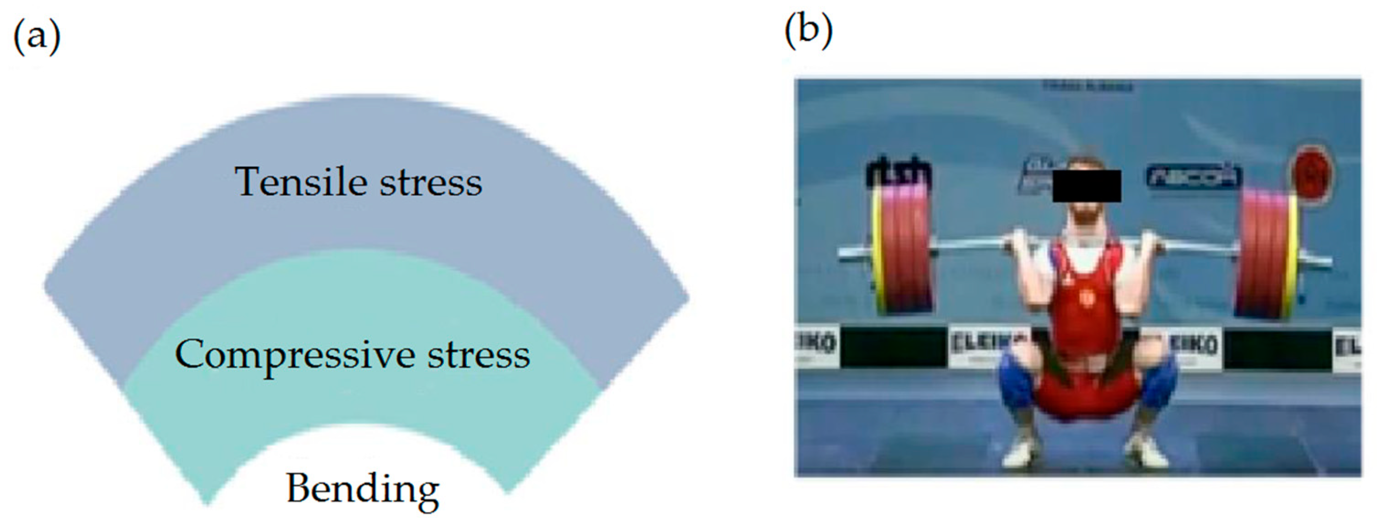
Figure 1. (a) An object, bending down, experiences tensile stress (stretching) at the top and compressive stress (squeezing) at the bottom. (b) Weightlifters often momentarily bend iron barbells during the lift.
Electronics 14 03316 g001
Figure 2. Workflow diagram.
Electronics 14 03316 g002
Figure 3. Material arrangement diagram in the exoskeleton.
Electronics 14 03316 g003
Figure 4. (a) Three-dimensional model of the exoskeleton. (b) Printed element (PLA-gray; Bioflex-white).
Electronics 14 03316 g004
Figure 5. Material arrangement diagram in the exoskeleton (b) compared to previous state (a).
Electronics 14 03316 g005
Figure 6. Side arrangement: (a) 3D model in Tinkercadonline (Autodesk, San Francisco, CA, USA); (b) printed element with visible internal structure (filling).
Electronics 14 03316 g006
Figure 7. Bent exoskeleton with visible weight because without it, the stresses were so strong that they straightened the exoskeleton.
Electronics 14 03316 g007
Figure 8. Print simulation with print data. Upper left corner: time data for each part (red—Bioflex; green—PLA).
Electronics 14 03316 g008
Figure 9. Manual material change with marked place.
Electronics 14 03316 g009
Figure 10. Model with automatic material change method from cleaning towers.
Electronics 14 03316 g010
Figure 11. Model with automatic tool change (extruder).
Electronics 14 03316 g011
Figure 12. Printed exoskeleton for the knee with an actuator with a moment of 400 kg·cm; (a) side view, (b) top view.
Electronics 14 03316 g012
Figure 13. Dimensions for a truss (rectangular): (a) diagonal; (b) side length; (c) truss wall thickness.
Electronics 14 03316 g013
Figure 14. Distances for gyroid filling (gyroid): (a) longest distance; (b) shortest distance; (c) wall thickness.
Electronics 14 03316 g014
Figure 15. Schematic diagram to show the manner of exoskeleton wearing.
Electronics 14 03316 g015
Table 1. Selected biomedical applications of soft–rigid 3D-printed interfaces (own elaboration).
AreaUsefulness
Medical robotsUsed to create soft robotic grippers that can handle delicate objects while providing a firm grip
Biomedical engineeringEssential for developing prosthetics and orthoses that require rigid support and soft skin contact areas for comfort
Using compliant catheters or surgical instruments with rigid handles and soft, body-safe tips
Wearable technologyUses these interfaces to integrate sensors into flexible but durable exoskeletons or clothing
Rehabilitation equipment, athletic and specialty footwearUse them to combine impact protection with user comfort
Rehabilitation and educational tools and toysUse them for durability and interactivity, combining soft touch with mechanical parts
Environmental sensing devicesUse soft, rigid interfaces for protective housings that can still adapt to surfaces
DesignPossibilities for devices/installations that are both structurally expressive and tactically engaging
Production of lightweight but durable components with built-in damping zones
Creation of adaptive structures that can deform under stress without failure
Table 2. Experimental test conditions.
Test NameLayer HeightInfill DensityInfill PatternNumber of Cycles
0.20 mm grid 15%0.20 mm15%Grid32
0.20 mm grid 30%0.20 mm30%Grid35
0.20 mm grid 50%0.20 mm50%Grid42
0.15 mm grid 15%0.15 mm15%Grid33
0.15 mm grid 30%0.15 mm30%Grid34
0.15 mm grid 50%0.15 mm50%Grid40
0.20 mm gyro 15%0.20 mm15%Gyroid29
0.20 mm gyro 30%0.20 mm30%Gyroid36
0.20 mm gyro 50%0.20 mm50%Gyroid45
0.15 mm gyro 15%0.15 mm15%Gyroid35
0.15 mm gyro 30%0.15 mm30%Gyroid39
0.15 mm gyro 50%0.15 mm50%Gyroid49
Table 3. Comparison of basic parameters of Bioflex and PLA.
ParameterBioflexPLA
Printing (extruder) temperature [°C]200–230190–220
Table temperature [°C]5060
Nozzle typeSteelSteel
Closed chamber (housing required)NoNo
Table typeGradient (powder)Smooth
Shore scale80A–85A60D–74D
Table 4. Selected methods’ parameters.
ParameterManual
Method
Auto w/Wipe TowerMulti-Tool Method
Waste Material per Switch [g]0.41.140.76
Transition Quality
(visual/smoothness)
Moderate (varied)GoodExcellent
Delamination Resistance (100 cycles)MediumHighVery high
Setup CostLowMediumHigh
Precision in Curved AreasLowMediumHigh
RecommendedRapid prototypingGeneral useClinical-grade models
Disclaimer/Publisher’s Note: The statements, opinions and data contained in all publications are solely those of the individual author(s) and contributor(s) and not of MDPI and/or the editor(s). MDPI and/or the editor(s) disclaim responsibility for any injury to people or property resulting from any ideas, methods, instructions or products referred to in the content.