1. Introduction
The braking systems of commercial vehicles must deliver high levels of performance and safety due to the large masses and elevated centers of gravity of such vehicles. As excessive deceleration or rear-wheel lock-up can critically impair lateral stability, precise braking control is essential for maintaining safe vehicle dynamics. Medium-duty and heavy-duty trucks and buses, which carry heavy loads, commonly use pneumatic braking systems capable of generating high braking forces. Compared with hydraulic systems, pneumatic systems have a simpler structure, offer easier maintenance, and enable more convenient connection and disconnection when trailers are attached. Furthermore, they are equipped with spring brakes, which automatically engage in the event of air pressure loss or system failure, enabling safe vehicle stoppage.
In recent years, the electronic parking brake (EPB) system, which was initially introduced in passenger cars [
1,
2], has been increasingly adopted in commercial vehicles. Recent studies have demonstrated advanced EPB architectures, which have also been integrated into commercial vehicles [
3,
4]. In medium-duty and heavy-duty commercial vehicles, pneumatic braking systems are commonly employed due to their ability to generate high braking forces suitable for large vehicle masses. Building on this principle, pneumatic EPB systems are configured with a solenoid-valve-based modulator, an EPB switch, and an electronic control unit (ECU), which enable both service and parking brake functions. Beyond their conventional parking functionality, pneumatic EPB systems can be extended to support user convenience features and provide emergency braking in the event of service brake failure. Herein, we propose a rule-based slip controller designed to ensure stable braking performance when a medium-duty commercial vehicle utilizes its EPB system for emergency braking.
The proposed system was developed using a model-based design (MBD) methodology [
5,
6] featuring a V-cycle development process, including requirements definition, controller design, modeling, code generation, simulation, and vehicle testing. MBD accelerates development and improves quality by facilitating systematic design and testing procedures and the early discovery of software errors. Moreover, it enables automated code generation and testing while also ensuring traceability. TRW Automotive utilized MBD with MATLAB
®/Simulink and Design Verifier [
7] during software development for their EPB system, which enabled early-stage formal verification and ensured high test coverage [
8]. Palanivelu et al. demonstrated the feasibility of MBD by modeling and experimentally validating pneumatic brake valves and chambers in Simcenter Amesim and MATLAB
® environments [
9]. In this study, we constructed an integrated validation environment based on MATLAB
®/Simulink (version 23.2, R2023b) and TruckSim (version 2017.1) to support automated testing and controller verification, which would enable the development of high-reliability software that complies with industry standards.
Sliding-mode controllers [
10,
11] and the current-based feedback controller [
12] have been proposed to implement emergency braking functionality in EPB systems that use a motor as an actuator. These control methods involve modeling the system based on the parameters of the DC motor and designing the controller based on the developed system model. However, for pneumatic braking systems, designing a controller based on a mathematical model is difficult due to the complexity of the spring brake actuator model [
13]. Herein, we propose a rule-based controller that determines the required brake pressure by processing two inputs: the wheel slip ratio and the EPB switch actuation angle. The slip ratio is classified into three control regions, and pressure commands are generated accordingly to prevent wheel lock while satisfying the driver’s braking requirement. The pressure commands are designed using a combination of lookup tables and incremental control logic based on previous control outputs, which ensures both smoothness and stability in control transitions.
The proposed control logic was initially verified across model-in-the-loop (MIL), software-in-the-loop (SIL), processor-in-the-loop (PIL), and hardware-in-the-loop (HIL) simulation environments, before being validated through real-vehicle tests involving a medium-duty commercial vehicle driven on dry asphalt, snow, ice, and split- road surfaces. Based on the experimental results, the proposed controller satisfies regulatory braking distance requirements while maintaining effective slip control and lateral stability under various loading and road conditions. Thus, pneumatic EPB systems are deemed viable fault-tolerant emergency braking solutions.
The remainder of this paper is organized as follows.
Section 2 describes the system architecture and development methodology.
Section 3 details the design of the rule-based control strategy.
Section 4 and
Section 5 present the MBD validation environment and the performance evaluation results from the real-world experiments, respectively. Finally,
Section 6 and
Section 7 discuss the overall findings and outline future research directions, respectively.
2. System Architecture and Development Methodology
2.1. Pneumatic EPB System Configuration
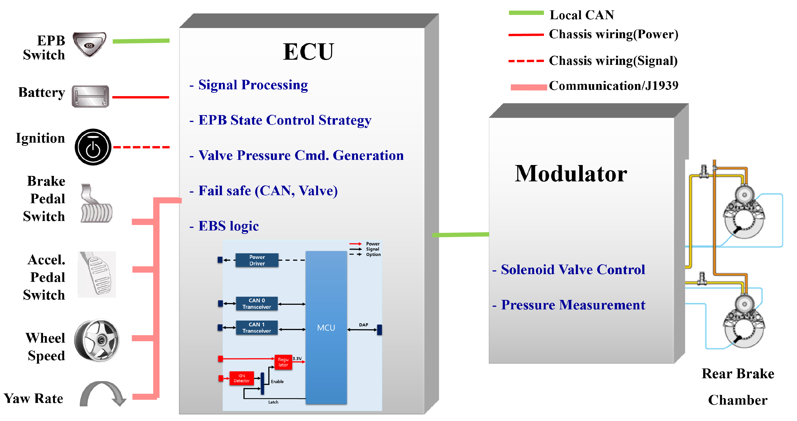
Figure 1 illustrates the configuration of a pneumatic EPB system, which comprises an air tank, an EPB modulator with valves, an ECU, and brake chambers. The ECU, equipped with a microcontroller unit (MCU), processes input signals, such as the EPB switch angle, vehicle dynamics data, driver inputs, and pneumatic pressure, to determine the EPB operating mode and the corresponding pressure command. The ECU then transmits a pressure command to the modulator. While the developed software integrates both electronic brake systems and EPB algorithms, these functionalities can be distributed across separate ECUs, depending on the system architecture. The modulator, also equipped with an MCU and solenoid valve control circuitry, is responsible for tracking and executing the pressure commands. However, the modulator is being developed externally and falls outside the scope of this study.
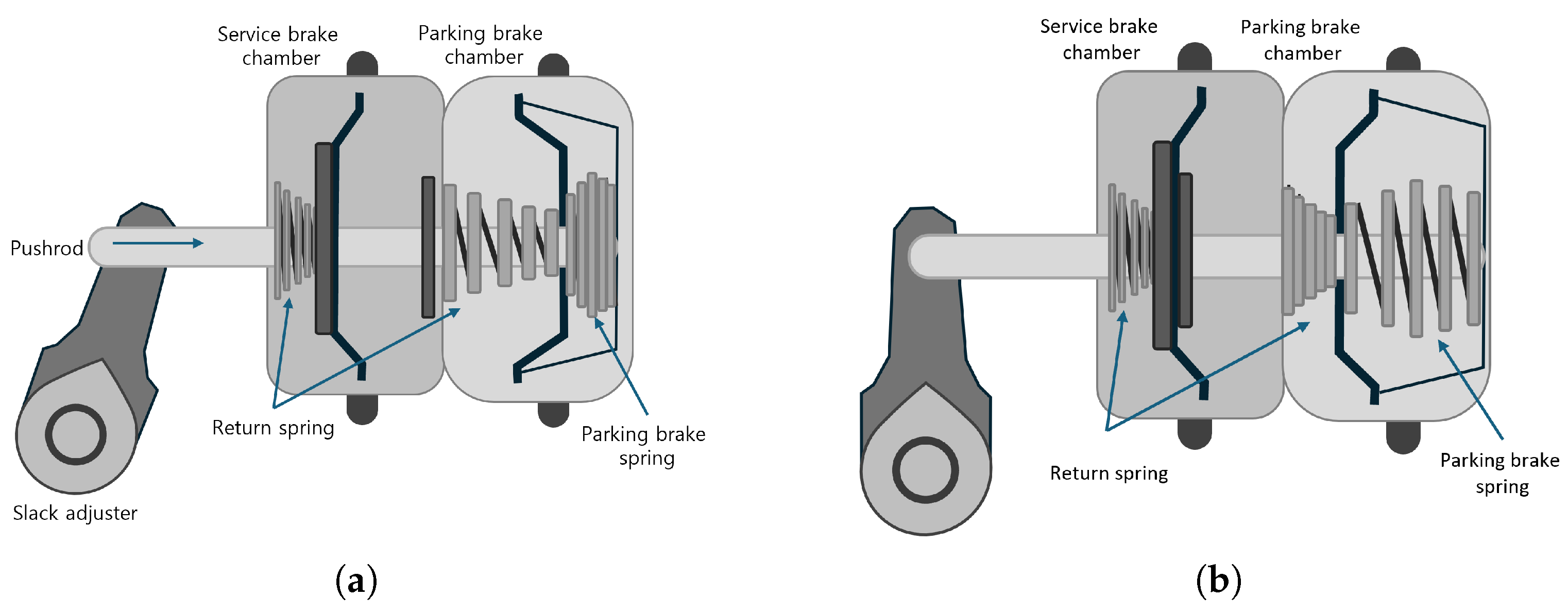
As illustrated in
Figure 2, the rear brake chamber in a pneumatic braking system performs service brake and parking brake functions. The EPB valve controls the air pressure within the parking brake chamber, which, in turn, regulates the application of the parking brake. The chamber converts pneumatic pressure into mechanical force, transmitting it through the push rod and linkage to execute braking [
13,
14,
15]. In the released state (
Figure 2a), compressed air is supplied to the parking brake chamber, which forces the diaphragm to compress the parking brake spring. This action retracts the push rod, thereby disengaging the brake. Conversely, in the applied state (
Figure 2b), the air is vented from the parking brake chamber, which allows the parking brake spring to expand and push the diaphragm and rod forward; this produces the requisite brake force. This configuration inherently supports a fail-safe mechanism: in the event of air supply failure or power failure, the spring force automatically engages the parking brake, ensuring vehicle safety [
13].
2.2. MBD Framework
Traditional development methods for control systems typically involve creating specifications that meet functional requirements, writing source code manually, and applying it directly to the target processor. However, every time requirements change or errors are detected, the code must be rewritten and retested, which renders the process time-consuming and error-prone. Moreover, the difficulty in tracing the relationships between the requirements, design models, source code, and test results can compromise both development efficiency and functional safety.
In contrast, MBD represents a systematic approach to building executable models that represent functional requirements. Even if requirements change, only the relevant subsystem models need to be updated, with the downstream impacts being automatically traced and retested. This method supports rapid experimentation with new control strategies, facilitates repeatable validation through simulation, and automates key development steps, such as reporting, code generation, and verification. Additionally, because each functional block is implemented as an independent software unit, MBD enhances software reusability, allowing validated modules to be adapted across different vehicle platforms and control applications. These characteristics alleviate the need for manual intervention and minimize human error, rendering MBD particularly effective for safety-critical automotive ECUs.
The MBD framework employed in this study involves a structured V-cycle process (
Figure 3) and was developed within the MATLAB
® (version 23.2, R2023b) environment. During the requirements specification phase, the EPB’s key functions—static application, static release, and dynamic braking—were clearly defined [
16]. Controller modeling was conducted in MATLAB
®/Simulink and Stateflow (version 23.2, R2023b) [
17,
18], where the slip-control algorithm was formalized and verified through MIL simulations using a TruckSim (version 2017.1) vehicle model. Automatic code generation was then performed using Embedded Coder (version 23.2, R2023b) [
19], and the generated C code was verified through MIL, SIL, and PIL simulations [
20]. Compliance with MISRA-C guidelines was ensured through static analysis [
7,
21], while coverage analysis [
20] confirmed the completeness of the test cases. Finally, HIL simulations were performed using a real pneumatic brake chamber and modulator to verify the controller’s real-time responsiveness. This structured workflow ensured traceability across requirements, models, and tests, thereby accelerating development [
22,
23] and increasing reliability while facilitating compliance with ISO 26262 [
24] and Automotive SPICE
® [
25] standards.
Previous research has demonstrated the feasibility of MBD for pneumatic brake systems. Palanivelu et al. [
9] proposed a comprehensive MBD methodology based on the V-model, successfully modeling phenomena such as valve dynamics, chamber pressure buildup, and actuator behavior. Their simulation results strongly agreed with experimental measurements, which confirms the validity of MBD for both component-level and integrated modeling of air-brake systems. Studies have also focused on hill-start assist control logic in pneumatic EPB systems, employing rule-based strategies and conducting co-simulation using MATLAB
®/Simulink, TruckSim, and AMEsim to tune brake release performance on sloped surfaces [
26,
27].
Although this study does not specifically target software-defined vehicle (SDV) architectures, the modular and hardware-decoupled design characteristics inherent in MBD naturally align with SDV principles. In this context, the EPB controller developed in this study could be adapted into a hardware-independent software module suitable for SDV deployment [
28]. The importance of SDV-based architectures for enhancing flexibility and scalability in the design of commercial vehicles has been underscored by recent research [
29].
3. Rule-Based Slip Control Strategy
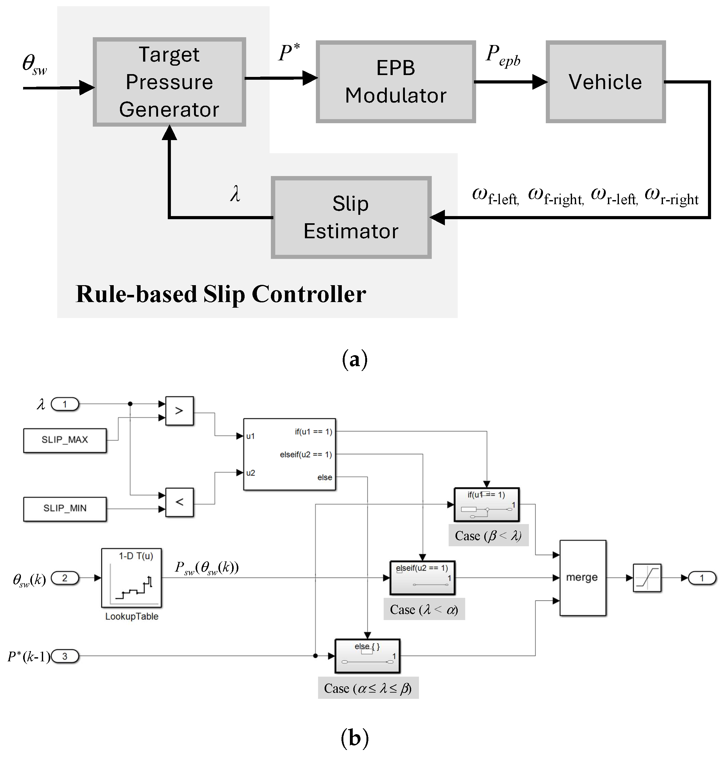
When the anti-lock braking system (ABS) malfunctions or cannot accept braking requests from other systems, the EPB enters dynamic braking mode to function as an emergency brake. The EPB can perform wheel slip control provided that all wheel speed sensors are operating normally. The proposed rule-based wheel-slip-control strategy considers the angle of the EPB switch (
) and the slip ratio (
), as shown in
Figure 4a. Based on Equation (
1),
is calculated from the wheel speed measured by the wheel speed sensor [
30]:
where
is the average speed of the front-left and front-right wheels,
is the speed of the rear-left wheel, and
is the speed of the rear-right wheel.
The internals of the “Target Pressure Generator” block in
Figure 4a are detailed in
Figure 4b. Equation (
2) presents an algorithm for generating the target pressure in three cases, depending on the magnitude of
, when the EPB operates in secondary braking mode:
subject to
bar.
Case (): The pressure commanded in the previous control step, , is increased by . This increment was experimentally tuned to provide effective slip recovery within the dynamic response limits of the modulator. If is too small, the chamber pressure increases too slowly, compromising slip-control performance; however, if it is too large, the modulator cannot accurately track the command due to its response limitations, which may cause instability. The tuned value of , thus, represents a trade-off, ensuring timely wheel slip recovery while maintaining stable braking control.
Case (): The pressure commanded in the previous control step, , is maintained.
Case (): The pressure command is generated as a function of the EPB switch actuation angle () using a one-dimensional lookup table. This lookup table defines an inversely proportional relationship between and the commanded pressure, with flat interpolation applied to ensure smooth transitions. To prevent overly sensitive responses, the mapping is designed such that small variations in do not cause abrupt or excessive changes in brake pressure. The breakpoints of the table were derived from MIL simulations and refined through experimental data. Although the exact numerical breakpoints cannot be disclosed due to confidentiality constraints related to the industry–academia collaboration, this configuration ensures that the commanded braking force increases in a controlled manner as the driver pulls the EPB switch, thereby enabling stable braking without abrupt variations.
In dynamic braking mode, the target pressure is limited to a value between 1 bar and 4.5 bar. When the vehicle is determined to be stationary, the pressure command is switched to 0 bar. At pressures exceeding 4.5 bar, the braking force is released because such pressures correspond to the fully disengaged state of the parking brake chamber. Additionally, at the boundary values of the slip ratio ( or ), the pressure command is maintained at the value in the previous step , which prevents abrupt transitions between regions. This approach avoids sudden pressure changes at the transition points, thereby preventing oscillations and ensuring stable braking behavior.
Additionally, the values of
and
were determined with reference to the general characteristics of the tire–road friction curve and calibrated through iterative full-scale vehicle tests. Research has shown that the peak longitudinal friction coefficient is generally achieved at slip ratios of 10–20% on dry asphalt, while much lower values are obtained on wet, snowy, and icy roads [
31,
32]. Accordingly, the values of
and
were selected from within the stable, rising segment of the tire-road friction curve to ensure reproducible slip control performance under various road conditions.
The proposed rule-based slip-control strategy represents a simple but effective approach to stabilizing vehicle behavior. By dividing into three control domains, the system adaptively adjusts the braking pressure to either maintain the current pressure, increase the pressure to restore , or follow the user-intended deceleration through a lookup table based on . This design ensures that slip is controlled without abrupt pressure changes, enabling stable modulation of the slip controller based on driver input.
4. MBD Validation
The MBD methodology was employed to validate the proposed control logic for EPB systems in commercial vehicles. The validation procedure progressed through MIL, SIL, PIL, and HIL simulation stages. This section describes the configuration of the validation environment in each stage.
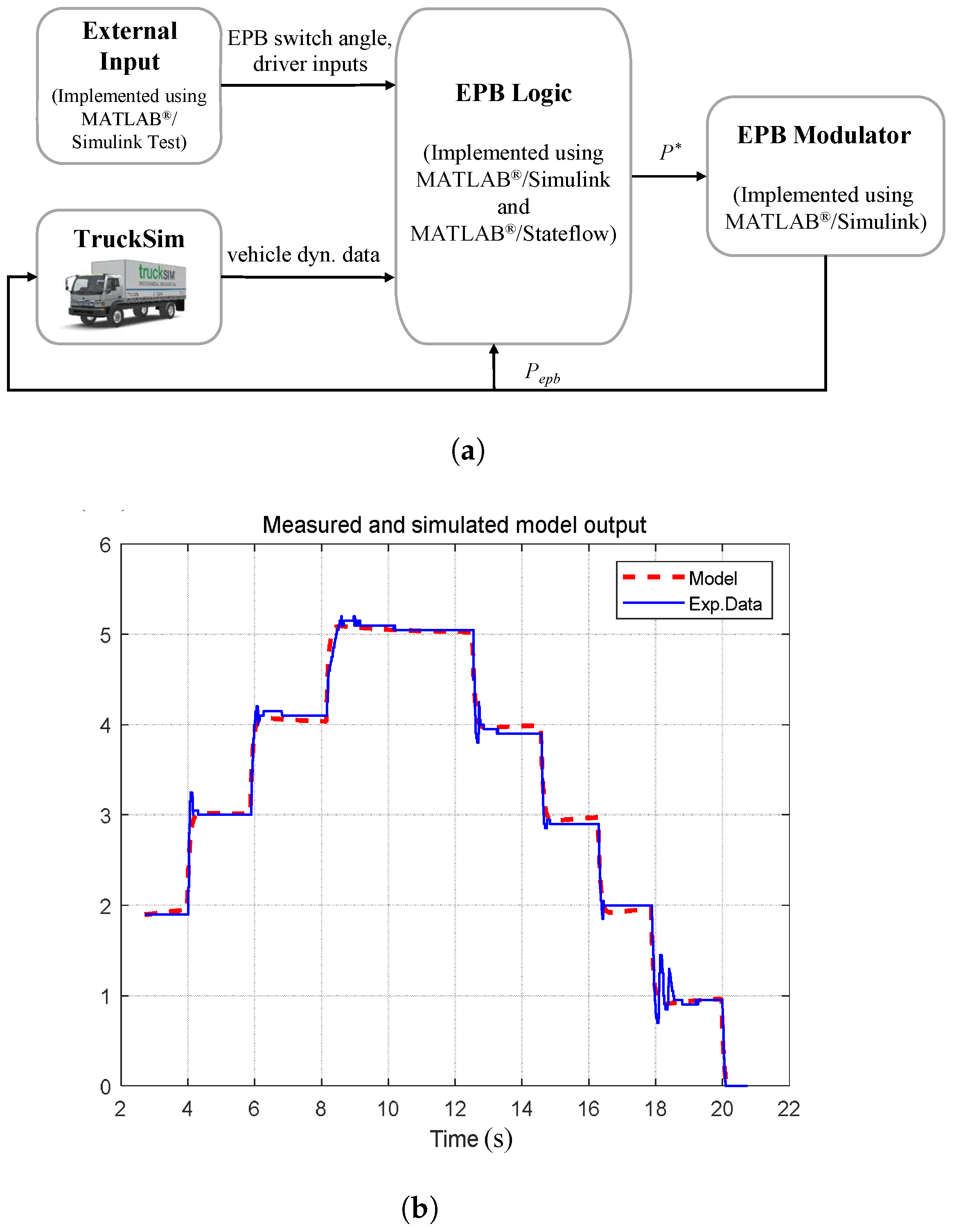
As shown in
Figure 5a, the MIL and SIL validation environments were built using MATLAB
® (version 23.2, R2023b) integrated with TruckSim (version 2017.1), while the EPB logic and modulator were implemented using Simulink and Stateflow. Based on the experimental results, the EPB modulator was modeled as a second-order system using the MATLAB
®/System Identification Toolbox (version 23.2, R2023b). The model’s consistency was verified by comparing the simulated modulator pressure output with the corresponding experimental data, as shown in
Figure 5b. The vehicle model (representing a medium-sized commercial vehicle), braking system (which altered its behavior according to the applied braking pressure), and road surface conditions were modeled in TruckSim (version 2017.1). This simulation environment enabled a pre-evaluation of the braking performance according to the road friction, thereby reducing the time required for controller tuning in the HIL simulation and real-vehicle test.
The dynamic test of the control logic was conducted using the MATLAB
®/Simulink Test (version 23.2, R2023b) [
20], which generated a test harness and provided external input and output interfaces. All input signals were predefined using Excel or Simulink Test Sequence blocks for requirement-based test-case generation, as well as test repetition and automation. Additionally, to simulate and receive real-time feedback on the vehicle’s dynamic characteristics using TruckSim (version 2017.1), we configured an environment for controlling the EPB switch and monitoring the output signal using a panel.
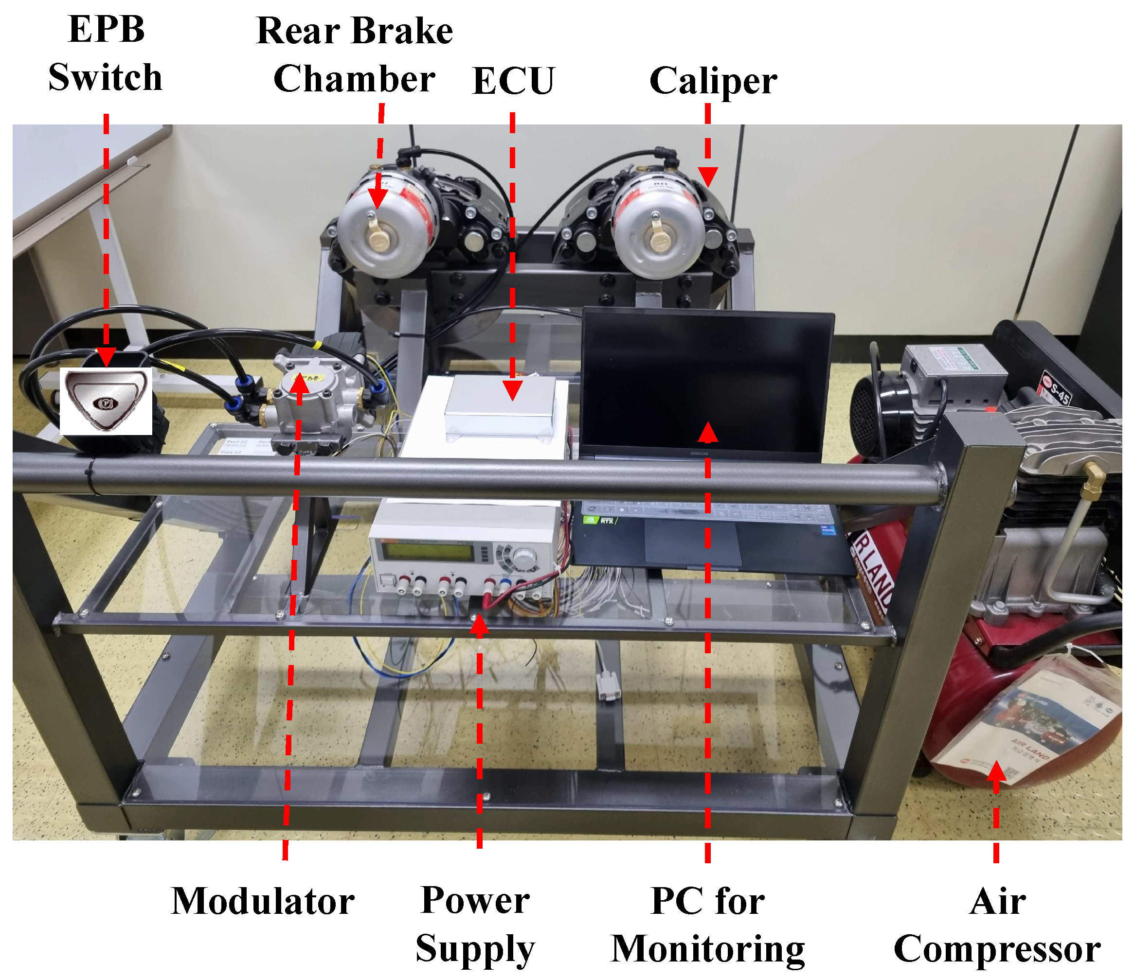
To validate the control logic in a real-time embedded environment, we constructed PIL and HIL simulation environments (
Figure 6) comprising an EPB switch, a rear brake chamber, a caliper, a dedicated ECU, a power supply, a monitoring PC, a modulator, and an air compressor that emulates a pneumatic system. However, a limitation of this setup is that the wheels could not physically rotate.
In the PIL stage, we executed the compiled control software on the target ECU to evaluate its accuracy and timing under realistic constraints. Then, during the HIL test, we connected the ECU to actual brake components to verify the EPB functions, including the modulator response. This integrated test environment enabled us to validate all aspects of the control system, from software logic to physical operation, across various input scenarios and environmental conditions.
5. Experimental Validation
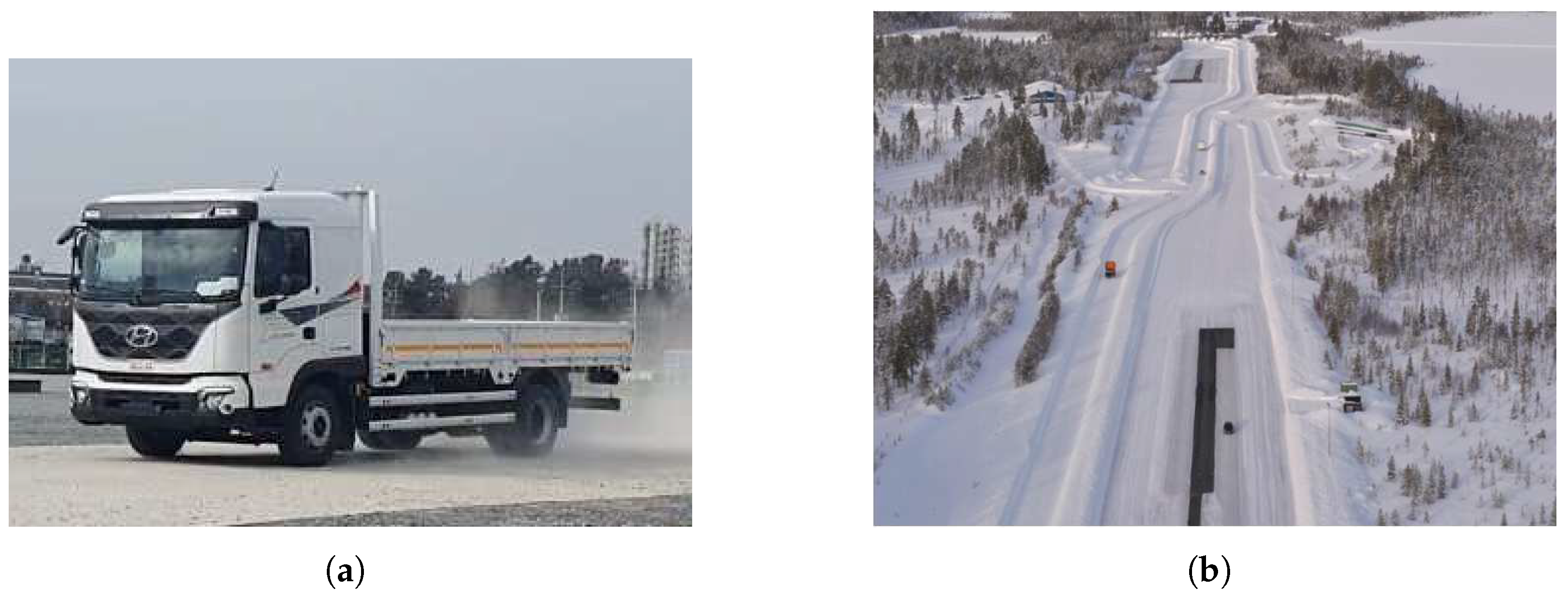
This section outlines the experimental validation of the proposed rule-based slip-control strategy for pneumatic EPB systems under various road and loading conditions. The developed pneumatic EPB system was tested after being installed in a commercial vehicle, which was a medium-duty truck with a curb weight of 5.5 tons (
Figure 7a). The real-vehicle tests were performed on dry asphalt, snow, ice, and split-
surfaces (
Figure 7b) under both unladen and 5-ton-loaded conditions. The initial braking speeds and road surfaces were selected to reflect the intent of international regulatory practices for braking tests [
33,
34,
35], while respecting safety constraints specific to EPB-only braking. Accordingly, very low-
conditions (ice and split-
) were evaluated at 30 km/h to provoke slip while avoiding destabilizing yaw, whereas snow was tested at an initial speed of 50 km/h to examine performance under low-
conditions. The adhesion coefficient ranges were
–
for asphalt,
–
for snow,
–
for ice, and
–
(wet asphalt) with
–
(ice) for the split-
surface.
If the main brakes failed while the vehicle was in motion, the dynamic braking function of the EPB would be activated when the driver indicated their intention to stop the vehicle by pulling the EPB switch, which would apply the braking force required to stop the vehicle. The experiment involved recording the wheel speed, yaw rate, and longitudinal acceleration to evaluate the control performance.
5.1. Experimental Results on Asphalt Road Under Unladen Conditions
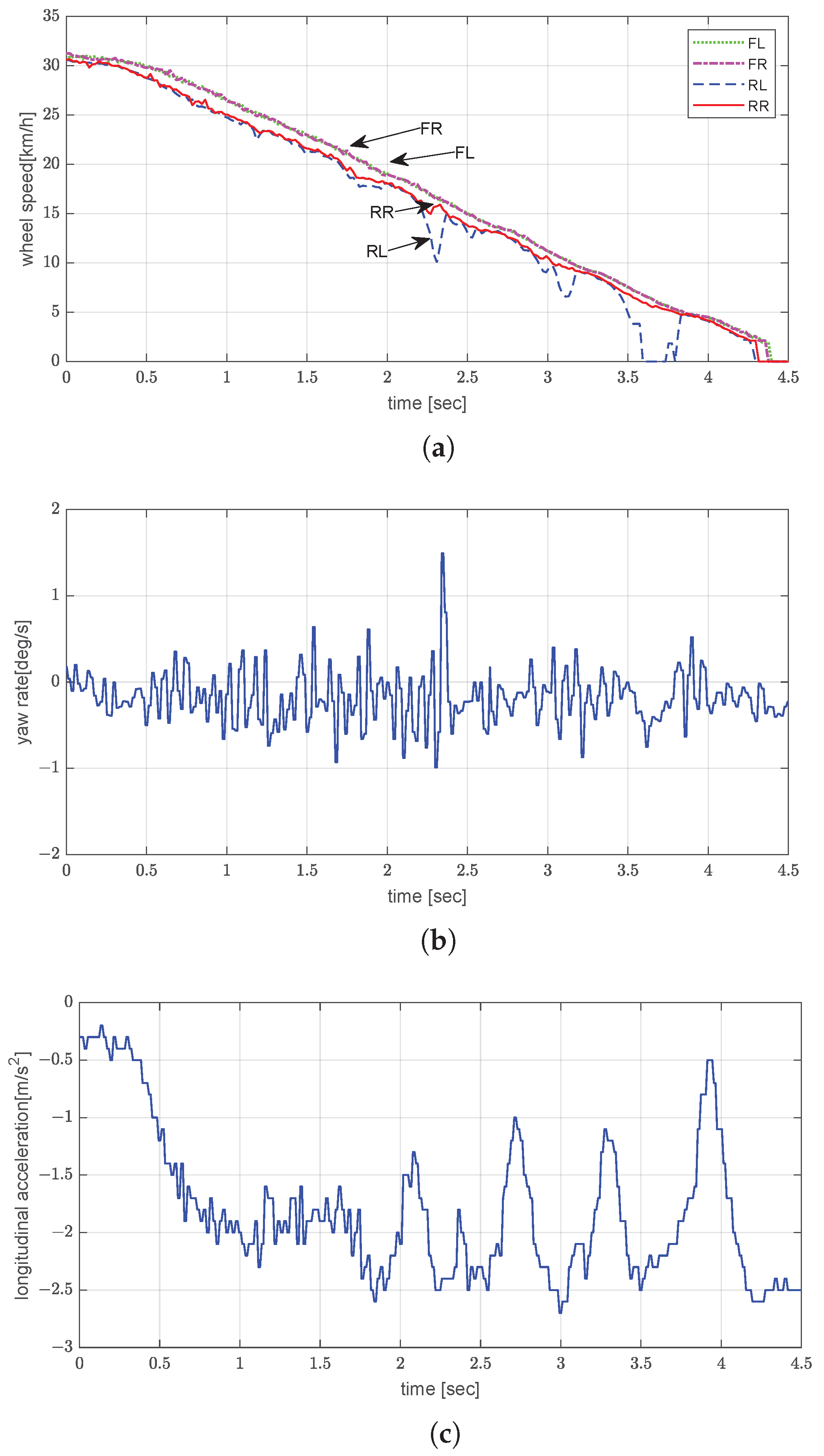
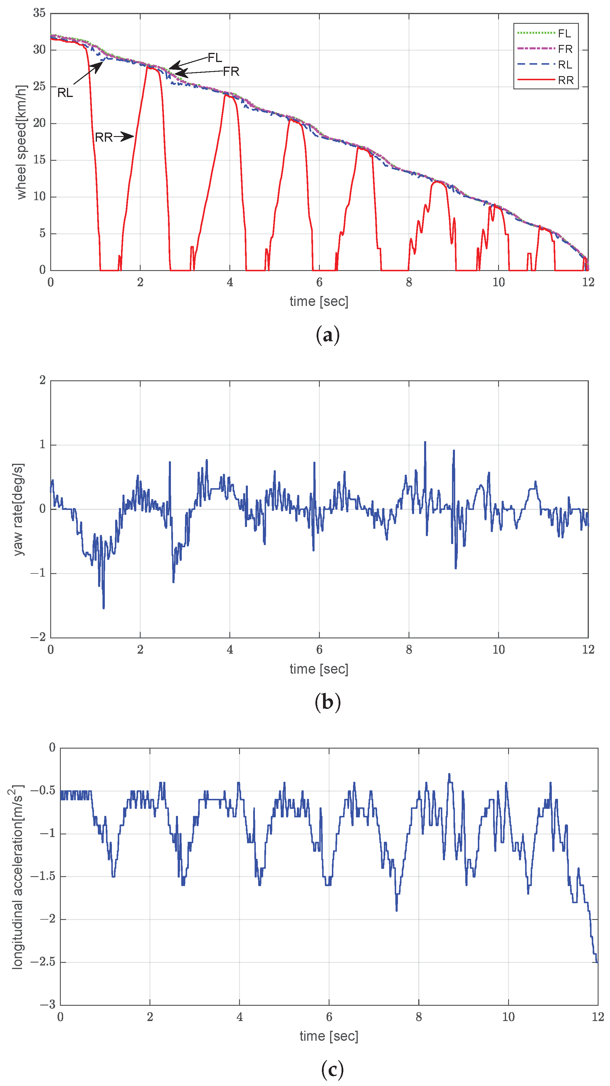
The asphalt test was performed with the vehicle unladen and being driven at an initial speed of approximately 30 km/h.
Figure 8 illustrates the EPB’s performance in this scenario. All four wheels decelerated uniformly and remained closely synchronized, with no evidence of premature locking or speed divergence between axles (
Figure 8a). The total stopping distance, estimated by integrating the wheel speed profile over the braking time, was approximately 17.9 m, which aligns with the expected deceleration behavior on high-friction asphalt under unladen conditions. The yaw rate oscillated around zero with a peak-to-peak amplitude of
, indicating stable yaw behavior (
Figure 8b). The longitudinal acceleration profile (
Figure 8c) indicates that the average acceleration achieved was approximately −1.8 m/s
2, with transient oscillations occurring at the same frequency as in the pressure control cycle.
Overall, the results on asphalt demonstrate that the EPB system can produce stable, controllable braking performance using only rear axle actuation, with effective slip management and minimal yaw disturbance under high-friction conditions.
5.2. Experimental Results on Snowy Road Under Unladen Conditions
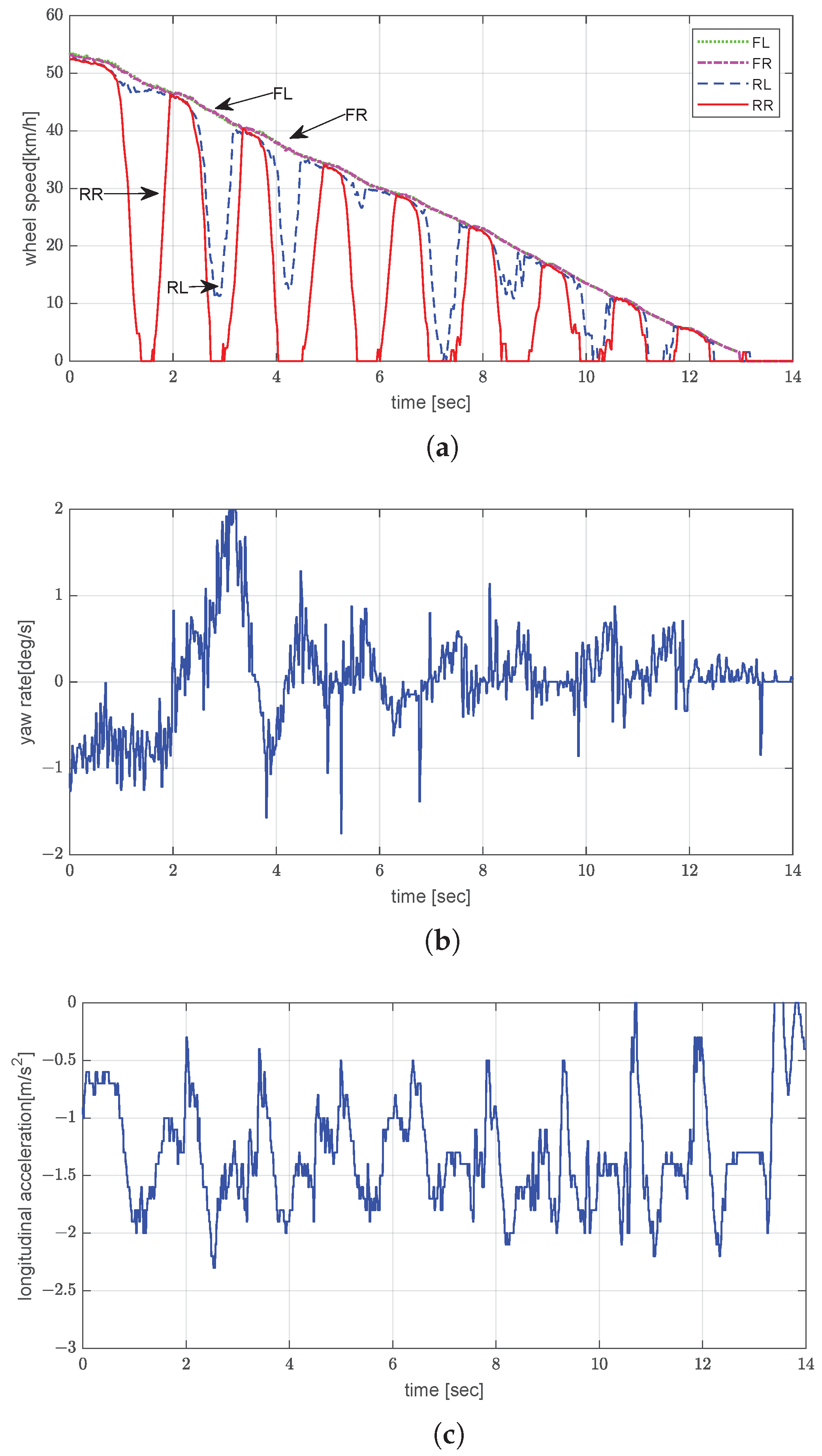
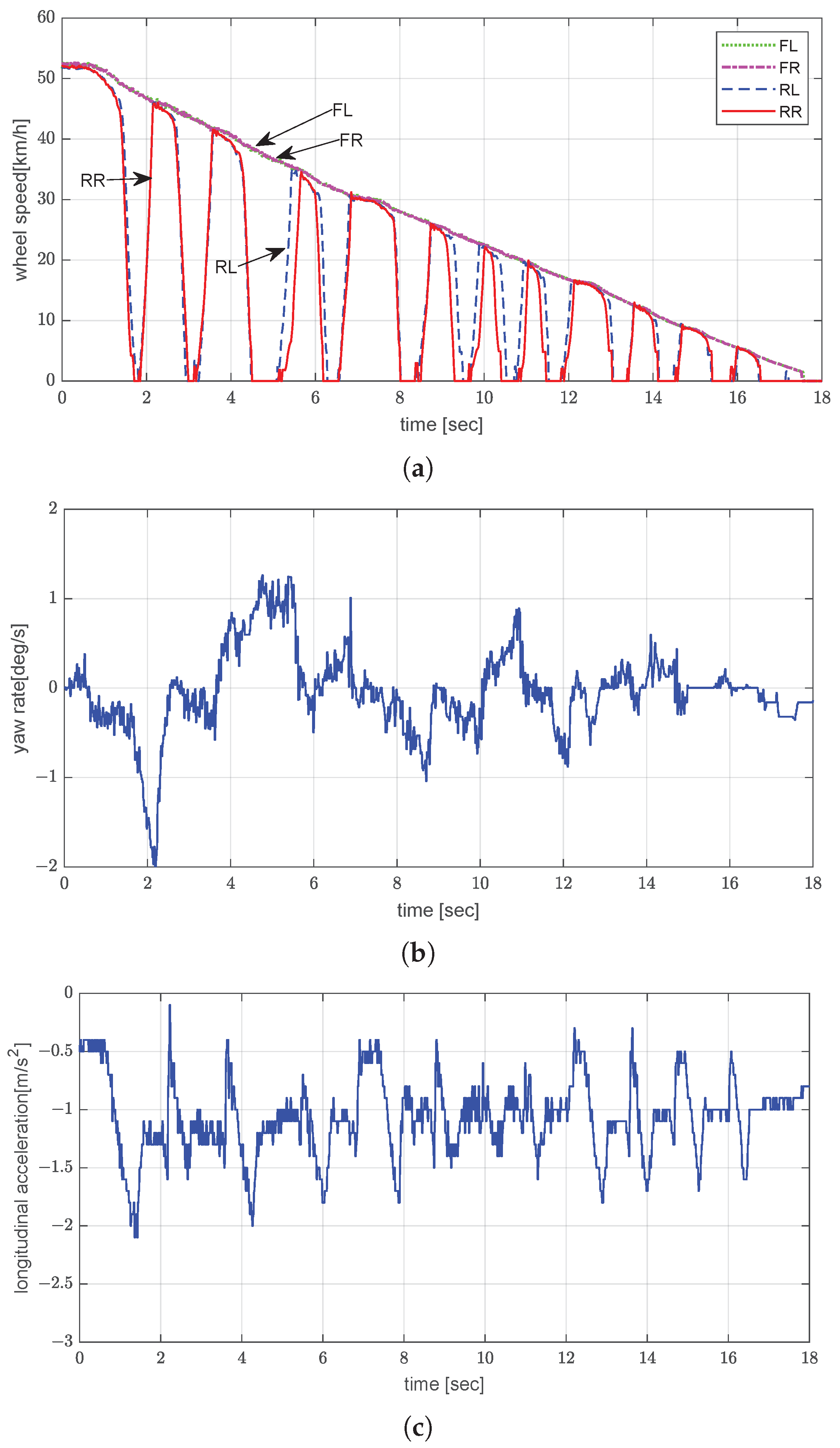
The snowy-road test was conducted with the vehicle unladen and being driven at an initial speed of approximately 50 km/h. As shown in
Figure 9a, the vehicle experienced frequent slip events on the low-friction surface, reflected in the oscillatory behavior exhibited by both the wheel speed and the yaw rate. The total stopping distance was approximately 116.7 m. The observed wheel-locking events lasted less than 1 s and are attributed to the exceedingly low surface friction of the test road. The yaw rate fluctuated within ±2°/s (
Figure 9b), which indicates marginal but controlled lateral instability. The deceleration profile (
Figure 9c) indicates an average longitudinal acceleration of approximately −1.4 m/s
2, with evident micro-lock and release cycles. These patterns demonstrate that even under snowy conditions, the EPB slip-control logic could maintain effective braking without triggering wheel lock.
5.3. Experimental Results on Icy Road Under Unladen Conditions
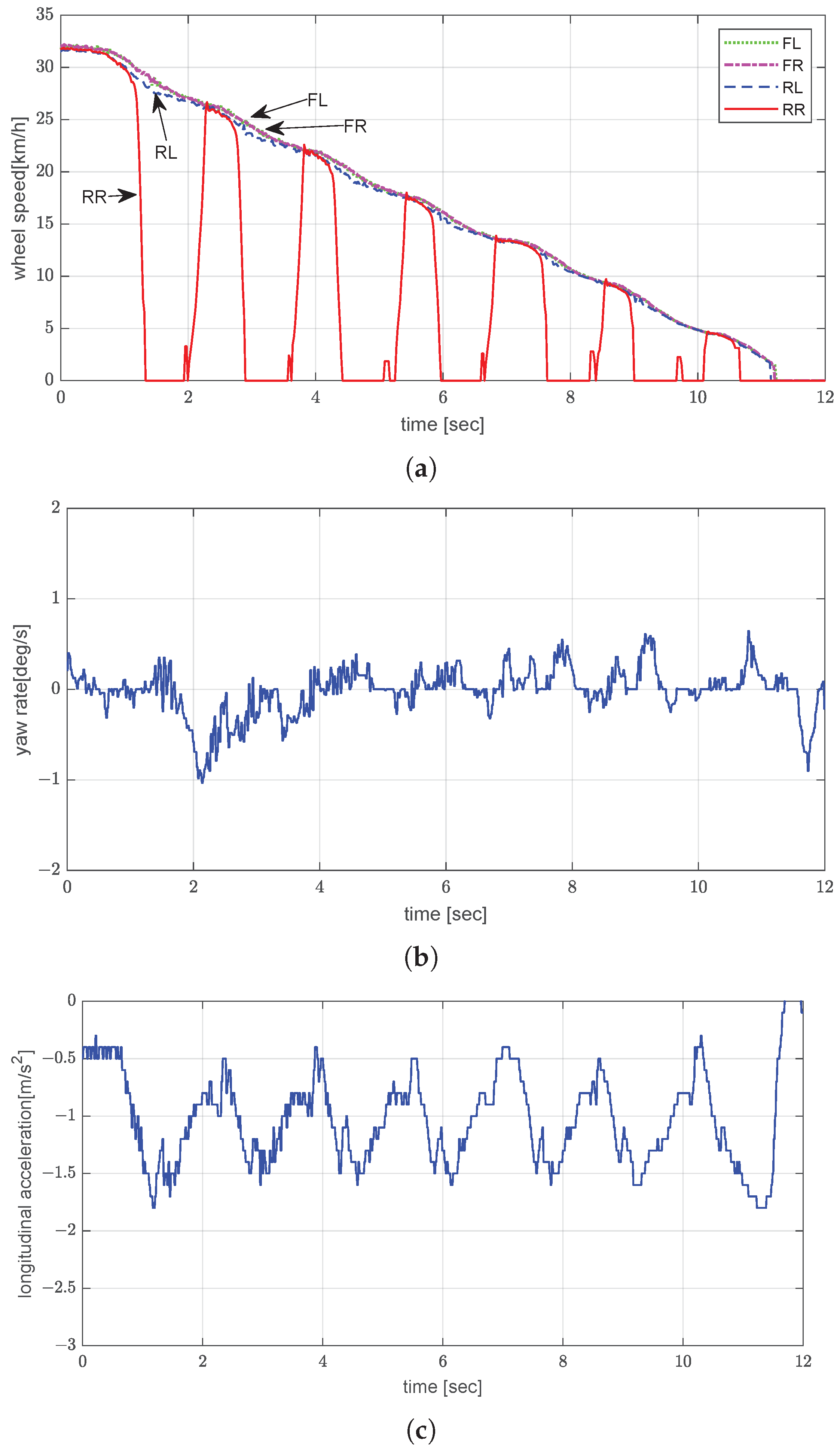
The icy-road test was performed with the vehicle unladen and being driven at an initial speed of 30 km/h. Significant wheel slip was observed to persist until approximately t = 13 s (
Figure 10a). This uncontrolled slip is attributed to the insufficient friction between the tire and the icy road surface, which hindered wheel slip recovery even when the braking force was temporarily reduced. Additionally, since only the rear wheels were being actively braked, the inertial torque of the vehicle body under unladen conditions may not have been sufficiently redistributed to promote quick slip recovery. The combination of these factors resulted in longer braking times despite the slip-control intervention. The total stopping distance under these conditions was estimated to be approximately 75.0 m. The amplitude of the yaw rate reached about 4.9°/s, which indicates lateral instability (
Figure 10b). Despite the low surface friction, the vehicle achieved a consistent but low acceleration rate of approximately −0.67 m/s
2 (
Figure 10c), which verifies that the controller can prevent complete wheel lock under extremely low-
conditions.
5.4. Experimental Results on Split-µ Road Under Unladen Conditions
On the split-
road, the unladen vehicle was braked from an initial speed of 30 km/h. The right side of the road was icy, while the left side was wet asphalt. As seen in
Figure 11a, the left and right wheels exhibited a divergence in speed during the early phase. The stopping distance was estimated to be approximately 72.9 m. The yaw rate reached a peak magnitude of 1.54°/s but quickly stabilized thereafter (
Figure 11b). The average acceleration was approximately −1.2 m/s
2 (
Figure 11c). These results confirm that the EPB controller can maintain acceptable directional stability, even on surfaces with varying friction conditions.
5.5. Experimental Results on Snowy Road Under Laden Conditions
On the snow-covered road, the vehicle, with a 5-ton load, was braked from an initial speed of 50 km/h. Compared with the unladen case, the wheels displayed smoother deceleration and smaller oscillations due to the increased normal force on the tires (
Figure 12a). Moreover, the stopping distance was estimated to be approximately 145.8 m due to the higher momentum and longer release modulation. As shown in
Figure 12b, the yaw rate varied from −2.1°/s to 1.3°/s. The peak-to-peak yaw rate was lower under the laden condition. The increased mass led to a higher yaw moment of inertia [
37], which inherently reduced the vehicle’s rotational sensitivity during braking. This increase in inertia suppressed the yaw response to the naturally occurring asymmetries in the braking force, such as those caused by uneven surface friction or rear-only braking; this resulted in a more damped yaw behavior in the laden condition. Additionally, the greater vertical load on the tires enhanced ground adhesion, reducing lateral slip and improving directional stability. The average longitudinal acceleration was around −1.1 m/s
2 (
Figure 12c). Even though the vertical tire load increased with the additional weight, the effective braking force per unit mass was reduced. Therefore, the vehicle exhibited a lower average longitudinal deceleration under the laden condition than under the unladen condition [
38].
Laden-vehicle tests on icy road were not carried out because preliminary trials indicated repeated yaw-instability events; consequently, for safety reasons, the icy road evaluation was limited to the unladen configuration.
5.6. Experimental Results on Split-µ Road Under Laden Conditions
In the split-
test under laden conditions (5 tons), the vehicle was braked from an initial speed of approximately 30 km/h. The right side of the road was icy, while the left side was wet asphalt. Under EPB control, the rear-right wheel, which was on the icy part of the road, exhibited severe vibration and was locked up multiple times, while the remaining wheels displayed relatively smooth deceleration (
Figure 13a). The calculated stopping distance under this condition was approximately 52.7 m, which highlights an improvement in braking efficiency due to increased tire load. As shown in
Figure 13b, the yaw rate oscillated between −1.2°/s and 0.8°/s. The average longitudinal acceleration was about −1.0 m/s
2 (
Figure 13c). In the split-
test, the average deceleration under the laden condition was not lower than that under the unladen condition. This result is attributed to differences in surface friction between test days. Thus, the control logic demonstrated robust slip-control performance under various load and surface conditions.
5.7. Comparison Experiment on Snowy Road Under Unladen and Laden Conditions Using ABS Control
To benchmark the EPB control strategy, a conventional ABS-controlled braking test was conducted with the vehicle driven on a snowy road in both unladen and laden configurations, with an initial speed of 60 km/h. Unlike the EPB-based slip-control strategy, which utilizes pneumatic actuation applied only to the rear axle, the tested ABS could independently regulate slip at all four wheels. This enabled precise compensation for wheel slip and lateral stability under varying surface conditions. The ABS logic dynamically adjusted the brake pressure at each wheel based on the instantaneous slip ratios. Notably, the ABS controller used in this study was not a commercially produced unit but a development-stage system utilized only for comparative analysis. The results are, therefore, intended to serve as a reference baseline, not as a direct evaluation of any existing mass-produced product.
As shown in
Figure 14a, all four wheels exhibited synchronized deceleration trends. However, in the laden case (
Figure 14d), more pronounced oscillations were observed, particularly in the rear wheels. The increased vertical load on the tires under the laden condition affected the transient slip response and tire deformation behavior, which can lead to amplified oscillations during slip-recovery cycles under ABS modulation [
38]. The yaw rate of the unladen vehicle under ABS control generally remained within ±1.2°/s (
Figure 14b). In the laden configuration (
Figure 14e), the yaw rate exhibited more significant fluctuations, occasionally exceeding ±2.0°/s and reaching momentary peaks of approximately −4.0°/s. The corresponding longitudinal accelerations were approximately −3.2 m/s
2 (unladen) and −2.4 m/s
2 (laden), as shown in
Figure 14c,f. When dynamic braking was performed using the EPB, the average deceleration was smaller than when ABS was used, which led to a longer braking distance; however, no significant difference in lateral stability was observed.
Table 1 summarizes the average decelerations and peak-to-peak yaw rates on various road surfaces across the two loading configurations. These experimental data demonstrate that the proposed rule-based EPB controller can ensure stable braking on various low-
surfaces and under different loading conditions. The EPB’s control performance in regulating wheel slip confirms its feasibility as a fault-tolerant emergency braking system for commercial vehicles.
6. Discussion
The proposed controller’s performance was evaluated based on the following regulatory criteria:
Stopping distance requirement: In the experimental evaluation, the unladen vehicle was braked from an initial speed of 30 km/h and reached a complete stop within approximately 4.3 s, which corresponds to a stopping distance of about 17.9 m (
Figure 8). Although NHTSA stipulates stopping distance requirements for initial speeds of 48 km/h [
35], the associated explanatory documents [
39] also provide reference values corresponding to 32 km/h for technical assessment. According to these reference data, the maximum emergency braking distance at 32 km/h is 25.3 m. Considering this benchmark, our results indicate that the EPB can ensure safe and effective stopping performance, demonstrating feasibility for secondary braking applications.
Wheel-locking requirement: While stringent requirements regarding wheel locking are not imposed on emergency braking systems for commercial vehicles, service brake standards stipulate that the rear wheels must not lock before the front wheels and that any locking event should not last longer than 1 s [
35]. In all test cases, the rear wheel lock durations remained under 1 s, with no loss of vehicle control.
Lateral stability requirement: In accordance with electronic stability control standards for passenger vehicles, the yaw rate should remain within ±3 to ±5°/s to ensure lateral stability. The proposed EPB slip controller maintained yaw rates well within this range across all scenarios, including surfaces with varying friction conditions [
40].
7. Conclusions and Future Work
This study introduced a rule-based slip-control strategy for pneumatic EPB systems in medium-duty commercial vehicles, the effectiveness of which was verified through both simulations and full-scale real-vehicle testing. The controller was developed within an MBD framework and validated across multiple stages, namely MIL, SIL, PIL, and HIL testing. Based on the experimental results, the proposed system achieved adequate stopping performance and maintained lateral stability even on low-friction surfaces such as snowy and icy roads. The findings also demonstrate that the pneumatic EPB system can ensure stable braking in the event of primary brake failure.
Building upon these results, future research will focus on the following directions:
Improving the EPB modulator’s responsiveness to reduce system reaction time, thereby enhancing slip recovery and stability during rapid transitions, especially on low-friction surfaces, such as icy roads.
Developing robust control algorithms to improve braking performance under heavy load on slippery roads, where the current rule-based logic exhibits limitations [
41].
Expanding HIL testing to cover diverse scenarios and exploring integration with other systems for cooperative and fault-tolerant braking control.
Author Contributions
Conceptualization, Y.S.S., J.S.C. and M.C.K.; methodology, Y.O.L. and Y.S.S.; software, Y.O.L. and S.K.; validation, Y.O.L. and Y.S.S.; formal analysis, Y.O.L., S.K., J.S.C. and M.C.K.; investigation, Y.O.L., J.S.C. and M.C.K.; resources, J.S.C., M.C.K. and Y.S.S.; data curation, Y.O.L.; writing—original draft preparation, Y.O.L.; writing—review and editing, Y.O.L. and S.K.; visualization, Y.O.L.; supervision, Y.S.S.; project administration, Y.O.L.; funding acquisition, Y.S.S. All authors have read and agreed to the published version of the manuscript.
Funding
This work was supported in part by Hyundai Motor Company through an industry–academia collaboration project (2021–2024). The funder supported requirements definition, provision of test vehicle and HIL resources, and assistance with experimental setup and data analysis but had no role in the decision to publish the results or in the writing of the manuscript. Additional support was provided by the Technology Innovation Program (No. 20014121, “Development of integrated Minimal Risk Maneuver technology for fallback system during autonomous driving”) funded by the Ministry of Trade, Industry and Energy (MOTIE, Republic of Korea), and by the Information Technology Research Center (ITRC) support program (IITP-2024-RS-2024-00437756) funded by the Ministry of Science and ICT (MSIT, Republic of Korea) supervised by the Institute for Information & Communications Technology Planning & Evaluation (IITP).
Data Availability Statement
Data are contained within the article.
Conflicts of Interest
Author Jae Seol Cho and Author Mu Chan Kwon are employed by Hyundai Motor Company. The remaining authors declare that they have no commercial or financial relationships that could be construed as potential conflicts of interest.
Abbreviations
The following abbreviations are used in this manuscript:
| ABS | Anti-lock braking system |
| ECU | Electronic control unit |
| EPB | Electronic parking brake |
| FL | Front left |
| FR | Front right |
| RL | Rear left |
| RR | Rear right |
| MBD | Model-based design |
| MIL | Model-in-the-loop |
| SIL | Software-in-the-loop |
| PIL | Processor-in-the-loop |
| HIL | Hardware-in-the-loop |
| Wheel slip ratio |
| EPB switch actuation angle |
| Commanded brake pressure at step k |
| Measured pneumatic pressure at step k |
| Pressure command mapped to EPB switch actuation angle at step k |
| Incremental pressure term for slip recovery |
| Average speed of front-left and front-right wheels |
| Speed of rear-left wheel |
| Speed of rear-right wheel |
| Yaw rate |
References
- Lee, Y.O.; Lee, C.W.; Chung, H.B.; Chung, C.C.; Son, Y.S.; Yoon, P.; Hwang, I. A Nonlinear Proportional Controller for Electric Parking Brake (EPB) Systems; SAE Technical Paper 2007-01-3657; SAE International: Warrendale, PA, USA, 2007. [Google Scholar] [CrossRef]
- Lee, Y.O.; Son, Y.S.; Chung, C.C. Clamping force control for an electric parking brake system: Switched system approach. IEEE Trans. Veh. Technol. 2013, 62, 2937–2948. [Google Scholar] [CrossRef]
- Chen, F.; Fu, Z.; Qiu, B.; Chen, G.; Mao, L.; He, Q.; Yang, L.; Mo, X.; Sun, X. Design and experimental research of a new bistable electronic parking brake system for commercial vehicles. Actuators 2025, 14, 195. [Google Scholar] [CrossRef]
- Dias, F.G.; Minutti, C.J.; Menezes, F.O. Vehicle System Integration (Electric Parking Brake); SAE Technical Paper 2021-36-0414; SAE International: Warrendale, PA, USA, 2021. [Google Scholar] [CrossRef]
- Barbieri, G.; Fantuzzi, C.; Borsari, R. A model-based design methodology for the development of mechatronic systems. Mechatronics 2014, 24, 833–843. [Google Scholar] [CrossRef]
- Mudhivarthi, B.R.; Saini, V.; Dodia, A.; Shah, P.; Sekhar, R. Model based design in automotive open system architecture. In Proceedings of the 2023 7th International Conference on Intelligent Computing and Control Systems (ICICCS), Madurai, India, 17–19 May 2023; pp. 1211–1216. [Google Scholar] [CrossRef]
- MathWorks. Simulink Design Verifier. 2025. Available online: https://www.mathworks.com/products/simulink-design-verifier.html (accessed on 22 February 2025).
- TRW Automotive. Develops and Tests Electric Parking Brake—Model-Based Design Case Study. 2015. Available online: https://www.mathworks.com/company/user_stories/trw-automotive-develops-and-tests-electric-parking-brake.html (accessed on 3 August 2025).
- Palanivelu, S.; Patil, J.; Jindal, A. Modeling and Optimization of Pneumatic Brake System for Commercial Vehicles by Model Based Design Approach; SAE Technical Paper 2017-01-2493; SAE International: Warrendale, PA, USA, 2017. [Google Scholar] [CrossRef]
- Wang, B.; Guo, X.; Zhang, C.; Xiong, Z.; Xia, H.; Zhang, J. Slide mode control for integrated electric parking brake system. Math. Probl. Eng. 2013, 2013, 216982. [Google Scholar] [CrossRef]
- Wang, B.; Guo, X.; Zhang, W.; Chen, Z. A study of an electric parking brake system for emergency braking. Int. J. Veh. Des. 2015, 67, 315–346. [Google Scholar] [CrossRef]
- Jing, H.; Liu, S.; Lin, Q.; Guan, Y. Backup control of vehicle braking system based on electronic parking brake actuator. In Proceedings of the 2023 7th CAA International Conference on Vehicular Control and Intelligence (CVCI), Changsha, China, 27–29 October 2023; pp. 1–6. [Google Scholar] [CrossRef]
- Soudagar, I.A.K.; Tota, P.D. Modelling and Simulation of Electro-Pneumatic Parking Brake System for Real Time Estimation of Pressure Inside Parking Brake Chamber. Master’s Thesis, Chalmers University of Technology, Gothenburg, Sweden, 2022. [Google Scholar]
- Zhang, Z.; Sun, N.; Chen, Y.; Ahmadian, M. Detailed modeling of pneumatic braking in long combination vehicles. SAE Int. J. Commer. Veh. 2021, 14, 245–258. [Google Scholar] [CrossRef]
- Ontario.ca. Spring (Parking and Emergency) Brake Subsystem|The Official Air Brake Handbook. 2022. Available online: https://www.ontario.ca/document/official-air-brake-handbook/spring-parking-and-emergency-brake-subsystem (accessed on 9 July 2025).
- MathWorks. Requirements Toolbox. 2025. Available online: https://www.mathworks.com/products/requirements-toolbox.html (accessed on 13 July 2025).
- MathWorks. Simulink. 2025. Available online: https://www.mathworks.com/products/simulink.html (accessed on 13 July 2025).
- MathWorks. Stateflow. 2025. Available online: https://www.mathworks.com/products/stateflow.html (accessed on 13 July 2025).
- MathWorks. Embedded Coder. 2025. Available online: https://www.mathworks.com/products/embedded-coder.html (accessed on 22 February 2025).
- MathWorks. Simulink Test. 2025. Available online: https://www.mathworks.com/products/simulink-test.html (accessed on 13 July 2025).
- MathWorks. Simulink Check. 2025. Available online: https://www.mathworks.com/products/simulink-check.html (accessed on 13 July 2025).
- Friedman, J. MATLAB/Simulink for automotive systems design. In Proceedings of the Design, Automation and Test in Europe Conference and Exhibition, Munich, Germany, 6–10 March 2006; pp. 1–2. [Google Scholar] [CrossRef]
- Shaout, A.; Pattela, S. Model based approach for automotive embedded systems. In Proceedings of the 2021 22nd International Arab Conference on Information Technology (ACIT), Muscat, Oman, 21–23 December 2021; pp. 1–7. [Google Scholar] [CrossRef]
- ISO 26262; Road Vehicles—Functional Safety. International Organization for Standardization: Geneva, Switzerland, 2018.
- Automotive Special Interest Group. Automotive SPICE Process Assessment Model, Version 4.0; Automotive Special Interest Group (SIG): Stuttgart, Germany, 2023. [Google Scholar]
- Peng, P.; Wang, H.; Wang, X.; Wang, W.; Pi, D.; Jia, T. Research on the hill start assist of commercial vehicles based on electronic parking brake system. Strojn. Vestn.-J. Mech. Eng. 2019, 65, 50–60. [Google Scholar] [CrossRef]
- Wu, L.; Wang, H.; Pi, D.; Wang, E.; Wang, X. Hill-start of distributed drive electric vehicle based on pneumatic electronic parking brake system. IEEE Access 2020, 8, 64382–64398. [Google Scholar] [CrossRef]
- Liu, Z.; Zhang, W.; Zhao, F. Impact, challenges and prospect of software-defined vehicles. Automot. Innov. 2022, 5, 180–194. [Google Scholar] [CrossRef]
- Saini, V.; Jain, A.; Meduri, P.; Verolt Technology Solutions GmbH. Revolutionizing Commercial Vehicles: Integrating Software-Defined Vehicle Architecture for Enhanced Electrical and Electronic Systems; SAE Technical Paper 2025-01-8138; SAE International: Warrendale, PA, USA, 2025. [Google Scholar] [CrossRef]
- Rajamani, R. Vehicle Dynamics and Control; Springer: Boston, MA, USA, 2006. [Google Scholar] [CrossRef]
- Guan, H.; Zhao, W.; Guo, K. Identification of maximum road friction coefficient and optimal slip ratio based on road type recognition. Chin. J. Mech. Eng. 2014, 27, 725–734. [Google Scholar] [CrossRef]
- Shahabi, A.; Kazemian, A.H.; Farahat, S.; Sarhaddi, F. Wheel slip ratio regulation for investigating the vehicle’s dynamic behavior during braking and steering input. Mech. Ind. 2021, 22, 17. [Google Scholar] [CrossRef]
- United Nations Economic Commission for Europe (UNECE). UN Regulation No. 13-H: Uniform Provisions Concerning the Approval of Passenger Cars with Regard to Braking, Annex 6—Adhesion Utilization and ABS Performance Tests; United Nations Economic Commission for Europe (UNECE): Geneva, Switzerland, 2023. [Google Scholar]
- Ministry of Land, Infrastructure and Transport. Regulation on the Performance and Standards of Motor Vehicles and Motor Vehicle Parts, Annex 7-4: Braking Performance Standards for Vehicles Equipped with Antilock Braking Systems; Ministry of Land, Infrastructure and Transport: Sejong, Republic of Korea, 2021. [Google Scholar]
- National Highway Traffic Safety Administration (NHTSA). Federal Motor Vehicle Safety Standards No. 121: Air Brake Systems; National Highway Traffic Safety Administration (NHTSA): Washington, DC, USA, 2009. [Google Scholar]
- COLMIS. COLMIS—Test Tracks. 2025. Available online: https://colmis.com/ (accessed on 13 July 2025).
- Schramm, D.; Hiller, M.; Bardini, R. Vehicle Dynamics Modeling and Simulation; Springer: Berlin/Heidelberg, Germany, 2014. [Google Scholar] [CrossRef]
- Gillespie, T.D. Fundamentals of Vehicle Dynamics; SAE International: Warrendale, PA, USA, 2021. [Google Scholar]
- National Highway Traffic Safety Administration (NHTSA). Federal Motor Vehicle Safety Standards no. 121: Air Brake Systems—Final Rule and Regulatory Impact Analysis; National Highway Traffic Safety Administration (NHTSA): Washington, DC, USA, 2009. Available online: https://www.govinfo.gov/content/pkg/CFR-2011-title49-vol6/xml/CFR-2011-title49-vol6-sec571-121.xml (accessed on 3 August 2025).
- National Highway Traffic Safety Administration (NHTSA). Federal Motor Vehicle Safety Standards No. 126: Electronic Stability Control for Light Vehicles; National Highway Traffic Safety Administration (NHTSA): Washington, DC, USA, 2007. Available online: https://www.govinfo.gov/content/pkg/CFR-2022-title49-vol6/xml/CFR-2022-title49-vol6-sec571-126.xml (accessed on 3 August 2025).
- Kwon, S.; Lee, Y.O.; Han, K.; Son, Y.S. Fuzzy PD controller design for wheel slip control via an electronic parking brake in commercial vehicle: Experimental study. Veh. Syst. Dyn. 2025. submitted for publication. [Google Scholar]
| Disclaimer/Publisher’s Note: The statements, opinions and data contained in all publications are solely those of the individual author(s) and contributor(s) and not of MDPI and/or the editor(s). MDPI and/or the editor(s) disclaim responsibility for any injury to people or property resulting from any ideas, methods, instructions or products referred to in the content. |
© 2025 by the authors. Licensee MDPI, Basel, Switzerland. This article is an open access article distributed under the terms and conditions of the Creative Commons Attribution (CC BY) license (https://creativecommons.org/licenses/by/4.0/).
