Article

Adaptive Learning Gain-Based Robust Attitude Control for Satellites with Time-Varying External Disturbances

Department of Electrical Engineering, Keimyung University, Daegu 42601, Republic of Korea
Electronics 2025, 14(16), 3298; https://doi.org/10.3390/electronics14163298
Submission received: 17 July 2025 / Revised: 6 August 2025 / Accepted: 17 August 2025 / Published: 19 August 2025

Abstract

Accurate and robust satellite attitude control is essential for a wide range of scientific and commercial space missions, including Earth observation, communication, and navigation. However, maintaining consistent tracking performance remains challenging when external disturbances are unknown, time-varying, or difficult to model accurately. This paper proposes an adaptive learning gain (ALG)-based nonlinear control framework for satellite attitude control under such uncertain conditions. The proposed method integrates a backstepping design with an ALG mechanism that dynamically adjusts control gains in real time according to the actual tracking error, without requiring prior knowledge of disturbance characteristics or extensive gain tuning. Unlike conventional adaptive or disturbance observer-based approaches, the controller guarantees that tracking errors remain within user-defined performance bounds while reducing excessive control effort. The effectiveness of the proposed scheme is validated through detailed simulations of a Multibody satellite model implemented in MATLAB/Simulink(R2024a),demonstrating improved tracking accuracy, adaptability, and control efficiency under significant disturbance variations. The results suggest that the proposed framework offers a systematic and practical solution for attitude control in aerospace applications where disturbance environments are highly uncertain.

1. Introduction

Satellite attitude control has been widely studied due to the growing demand for precise and robust orientation in scientific and commercial missions, such as Earth observation, interplanetary exploration, satellite navigation, and large-scale satellite constellations, including SpaceX’s Starlink program [1,2]. These missions require maintaining accurate pointing performance over long durations under various operational conditions. In satellite navigation systems, attitude stability is critical to ensure reliable signal coverage and precise orbit determination [2]. Small satellite missions, such as those designed to monitor space weather effects in low Earth orbit, also rely on high-performance attitude control to achieve their measurement objectives despite limited onboard resources [1,3]. In addition, Earth observation platforms with high-resolution optical sensors depend on precise attitude stabilization to avoid image degradation caused by micro-vibrations and external disturbances. As satellite systems become more complex, ensuring reliable attitude control has become a critical challenge. The increasing trend toward satellite miniaturization and large constellations further imposes constraints on available computational resources and actuator capabilities. Moreover, satellites operating under periodic dynamic conditions—such as those in Sun-synchronous orbits or with cyclic thermal effects—require attitude control strategies that remain robust against time-varying dynamics and parametric uncertainties [4]. At the same time, the need for autonomous operation requires control systems that can adapt to time-varying environments and uncertain disturbances while minimizing operator intervention.
To improve attitude control performance under these conditions, various advanced control strategies have been proposed. Nonlinear backstepping control and robust finite-time control methods have been widely used to achieve accurate tracking under bounded disturbances by constructing Lyapunov functions and designing stabilizing feedback laws [5]. These techniques can guarantee convergence and robustness, but their performance often depends on conservative gain selection to account for worst-case uncertainties. Optimal control and feedback linearization approaches have been applied to enhance transient response and steady-state accuracy by exploiting model information and minimizing control effort [6,7,8]. However, these methods require precise system modeling and may be sensitive to parameter variations or unmodeled dynamics. Adaptive and hybrid adaptive control techniques have been developed to compensate for parameter uncertainties and actuator faults by updating control parameters in real time [9,10]. While these approaches improve adaptability, they often rely on tuning adaptation gains and ensuring persistent excitation conditions, which can be difficult to guarantee in practical satellite missions. Recently, nonlinear MPC schemes have been applied to satellite attitude control for handling nonlinear dynamics and actuator constraints [11]. Sliding mode control has also been applied due to its strong robustness against matched disturbances and its ability to reject bounded uncertainties through discontinuous control laws, and recent studies have further developed adaptive gain strategies within this framework to enhance robustness under time-varying conditions [12,13]. Nevertheless, this approach frequently suffers from chattering issues that can induce wear or saturation in actuators. In addition, nonlinear dynamic inversion and model predictive control frameworks have been investigated to handle constraint satisfaction and performance optimization in real time [14]. These methods offer to enforce input and state constraints, but they require high computational resources and careful design to maintain stability under time-varying conditions. Although these methods have demonstrated good performance in many applications, they often rely on fixed-gain designs or disturbance observers that require prior knowledge of disturbance characteristics. As a result, their effectiveness can degrade significantly when the disturbances are time-varying, exceed expected bounds, or include high-frequency components. In such cases, control performance becomes strongly dependent on disturbance magnitude and model accuracy, and maintaining consistent tracking accuracy without excessive control effort remains challenging [15,16,17,18,19].
Although conventional nonlinear and adaptive controllers have improved attitude tracking performance, they often require high-gain feedback or extensive gain tuning to achieve satisfactory robustness. High-gain observers and adaptive control techniques have been widely used to estimate disturbances and improve transient response, particularly in systems with matched uncertainties and rapidly changing dynamics [20,21]. However, these methods can significantly amplify measurement noise and generate large control inputs when the disturbances are time-varying, unmodeled, or contain high-frequency components. This amplification can excite unmodeled dynamics, cause actuator saturation, or degrade stability. Barrier Lyapunov function (BLF) and prescribed performance function (PPF) control frameworks have been proposed to enforce explicit transient and steady-state error constraints under bounded disturbances [22,23,24,25,26,27]. These approaches guarantee convergence within predefined bounds but typically require careful parameter selection and rely on fixed or increasing gains to satisfy performance constraints. As a result, the control effort often becomes conservative and excessive when actual disturbances are smaller than worst-case assumptions. The tuning of BLF and PPF parameters is usually based on empirical trial-and-error procedures. However, in practical scenarios where disturbance intensity may vary over time, it is desirable for the control gain to both increase and decrease based on the tracking error dynamics. Such adaptability prevents excessive control effort under mild disturbances and mitigates the risk of feedback gain overestimation that often arises in conventional adaptive and prescribed performance control schemes. To eliminate the singularity issue commonly observed in PPC-based control laws, a logarithmic error transformation function is employed, ensuring the control input remains bounded near the prescribed performance boundaries [25]. Appointed-time convergence has been achieved using time-scheduled gain adaptation techniques [26]. These methods focus on enforcing convergence within a predefined time interval. In another approach, command-filtered tracking control has been employed to handle time-varying parameters and input delays [27]. However, this method requires additional dynamic filters, which increase the number of design parameters and can complicate controller tuning. Disturbance observer-based control methods have also been developed to estimate and compensate for external disturbances in real time [28]. Although these observers improve robustness, their performance depends strongly on the accuracy of disturbance modeling and the appropriate selection of observer gains. When disturbance characteristics change rapidly or deviate from the assumed models, estimation errors can degrade tracking accuracy. Self-tuning and variable PID strategies have been used to improve adaptability and reduce manual tuning effort [29,30]. These methods dynamically adjust control gains based on real-time error signals but still require multiple design parameters and often lack rigorous guarantees on transient error bounds. Despite these advances, maintaining consistent tracking performance without excessive control effort remains challenging when disturbances are unknown, time-varying, or exceed expected levels. Therefore, there is still a need for control schemes that can automatically adjust gains according to the actual tracking error, avoid unnecessarily high gains, reduce dependence on prior disturbance knowledge, and simplify the tuning process.
While significant progress has been achieved in adaptive and disturbance observer-based control approaches, many existing methods still require extensive gain tuning or rely on prior disturbance information that may not be available in practice. To address these limitations, this paper proposes an adaptive learning gain (ALG)-based nonlinear control framework that integrates a backstepping design with a self-updating gain mechanism to regulate satellite attitude dynamics. The proposed method adaptively adjusts the control gains in real time according to the actual tracking error without requiring disturbance estimation or manual gain mapping procedures. Compared to conventional high-gain adaptive control strategies, the presented approach enables the tracking error to remain within user-defined performance bounds while reducing unnecessary control effort. Furthermore, the effectiveness of the proposed framework is demonstrated through MATLAB/Simulink simulations using a detailed Multibody satellite model.
The main contributions of this paper can be summarized as follows:
  • An ALG-based attitude control method is developed for nonlinear satellite dynamics subject to unknown and time-varying external disturbances.
  • The proposed controller guarantees that tracking errors remain within prescribed performance bounds without requiring any prior knowledge of disturbance magnitudes or extensive gain tuning.
  • A self-updating gain mechanism is introduced that dynamically increases the control gain in the presence of large tracking errors and reduces it as errors decrease, thereby preventing excessive control input and improving efficiency.
The remainder of this paper is organized as follows. Section 2 describes the problem formulation and the mathematical model of the satellite attitude dynamics. Section 3 presents the design of the proposed ALG-based control scheme. Section 4 provides the simulation setup and results using a detailed Multibody satellite model implemented in MATLAB/Simulink to validate the effectiveness of the proposed method. Finally, Section 5 concludes the paper and discusses potential directions for future research.

2. Satellite Dynamics

In this study, we focus on a class of small rigid-body satellites commonly used in attitude control research. The satellite is actuated by three orthogonal reaction wheels, and its dynamics are subject to time-varying disturbances, including interaction effects between the wheels themselves. Specifically, the torque applied along one axis may indirectly affect the other axes due to mechanical coupling and internal dynamics, which act as unstructured and time-varying internal disturbances. This scenario underscores the necessity of a robust adaptive control framework. The modeling assumes a symmetric and constant inertia matrix, and the satellite’s motion is governed by Euler’s equations for rigid-body rotation. The modeling framework and assumptions are described in this section, while the specific numerical values for mass, inertia, and geometrical parameters are provided later in Section 4.
The unit quaternion q is expressed as
q = [ q η q ϵ T ] T = [ q η q ϵ 1 q ϵ 2 q ϵ 3 ] T R 4 × 1
where q η = cos ( θ / 2 ) and q ϵ = ϵ sin ( θ / 2 ) , with θ representing the Euler angle and ϵ = [ ϵ 1 ϵ 2 ϵ 3 ] T R 3 denoting the Euler axis. The unit quaternion adheres to the following constraint:
q η 2 + q ϵ T q ϵ = 1 .
The kinematic equation for satellite attitude dynamics is given by
q ˙ = 1 2 ω q = 1 2 H ( q ) ω
where the matrix H ( q ) is defined as
H ( q ) = q ϵ 1 q ϵ 2 q ϵ 3 q η q ϵ 3 q ϵ 2 q ϵ 3 q η q ϵ 1 q ϵ 2 q ϵ 1 q η
Here, ω = [ ω p , ω q , ω r ] T R 3 is the angular velocity vector of the spacecraft expressed in the body-fixed frame with respect to the orbital frame, and ⊗ denotes the quaternion multiplication operator.
The rotational dynamics of the satellite, governed by Euler’s rotational equations, are described as
ω ˙ = J 1 ( ω × J ω ) + J 1 u + J 1 d = J 1 ( J r J q ) ω q ω r ( J p J r ) ω r ω p ( J q J p ) ω p ω q = CF + J 1 τ p τ q τ r = u + J 1 d p d q d r = d
where CF = [ C F p , C F q , C F r ] is the Coriolis force term, and J = diag ( J p , J q , J r ) R 3 × 3 is the inertia matrix of satellite. × indicates the symbol of the cross product. u R 3 is the control torque, and d R 3 is the external disturbance injected in the satellite. The external disturbance satisfies following assumption.
 Assumption 1. 
The external disturbance has an upper limit δ i m a x , i [ p , q , r ] such that | d i | = | δ i | δ i m a x .

3. Control Methodology

3.1. Conventional Quaternion Controller

The quaternion-based attitude error is defined as
e q = [ e η e ϵ T ] T = q q ¯ d R 4 × 1
where e η R and e ϵ R 3 represent the scalar and vector components of the quaternion error, respectively. The reference quaternion is given by q d = [ q η d ( q ϵ d ) T ] T R 4 , and its conjugate is denoted as q ¯ d = [ q η d ( q ϵ d ) T ] T .
The dynamics of the quaternion error are expressed as
e ˙ q = 1 2 ω e q = 1 2 e ϵ T e η I 3 × 3 + S ( e ϵ ) ω .
To simplify the representation, the error is reformulated as z = [ 1 | e η | e ϵ ] T . The time derivative of z is given by
z ˙ = 1 2 G T ( e q ) ω
where
G T ( e q ) = s i g n ( e η ) e ϵ T e η I 3 × 3 + S ( e ϵ ) R 4 × 3 .
A Lyapunov candidate function for stability analysis is chosen as
V z = z T z
and its time derivative is derived as
V ˙ z = z T G T ( e q ) ω = z T G T ( e q ) ( e ω + ω d ) .
The desired angular velocity ω d is designed using a feedback term as follows:
ω d = K G ( e q ) z = [ ω p d , ω q d , ω r d ] T
where K = diag ( k 1 , k 2 , k 3 ) is a diagonal matrix of positive control gains, with k i > 0 for i { 1 , 2 , 3 } .

3.2. Proposed Angular Velocity Controller with Adaptive-Learning Gain

The angular velocity tracking error between the actual angular velocity ω and the desired value ω d is defined as
e i = ω i ω i d , i { p , q , r } .
Based on (5), the dynamics of the angular velocity error can be derived as
e ˙ i = 1 J i ( C F i + τ i + d i ) ω ˙ i d , i { p , q , r } .
To compensate for the tracking error, the control torque is designed as
τ i = C F i + J i ( k ^ i e i + ω i d )
where k ^ i is an ALG to be specified.
Substituting (15) into (14), the closed-loop tracking error dynamics becomes
e ˙ i = k ^ i e i + d i J i , i { p , q , r } .
 Assumption 2. 
There exists an unknown time-varying ideal positive gain K i * ( t ) satisfying the following conditions:
K i * ( t ) > k ^ i ( t ) K ̲ i * K i * ( t ) K ¯ i * sup t | K ˙ i * ( t ) | = κ i , i { p , q , r }
where K ̲ i * , K ¯ i * , and κ i are unknown positive constants. When k ^ i replaces K i * in (16), the ideal gain K i * adapts according to the disturbance effect to keep e i within the desired bound ε i .
The adaptive update law for the learning gain is formulated as
k ^ ˙ i = α ( k ^ i ) γ i e i 2 2 π arctan ( M ( | e i | ε i ) ) + ( 1 α ( k ^ i ) ) μ
where
0 α ( k ^ i ) = 1 2 2 π arctan ( M ( k ^ i k i   min ) ) + 1 1
where γ i is the learning rate, such that γ i > 1 , M is a large positive constant for approximating the signum function using the inverse tangent function, such that 2 π arctan ( M x ) sign ( x ) , ϵ i is a small positive constant representing the magnitude of the desired bound, α is a smooth function operating such that, when k ^ i is larger than k i min , α can approximate one, α 1 , and, when k ^ i is close to k i min , α can approximate zero, α 0 , with 0 < α < 1 , k i min is a positive constant, and μ is a positive constant larger than μ > γ i ε 2 i . The initial value of k ^ i is defined as k ^ i ( 0 ) > k i min . Therefore, the lower bound of k ^ i can be determined using (18) as inf | k ^ i ( t ) | = k i min .
 Remark 1. 
In the proposed adaptive update law (18), the learning gain k ^ i increases until the error magnitude | e i | is reduced below the threshold ε i . Once the error remains within the bound, k ^ i is allowed to decrease, maintaining the minimum necessary control effort to ensure accuracy. This prevents the unnecessary growth of control gains and enhances efficiency.
 Theorem 1. 
Consider the closed-loop tracking error dynamics described in (16), under the conditions stated in Assumptions 1 and 2. With the adaptive update law defined in (18), both the tracking errors and the estimation errors of the adaptive gains are uniformly ultimately bounded, and the Lyapunov function V ( t ) satisfies the following inequality:
lim t V ( t ) Δ p + Δ q + Δ r min ( a p , a q , a r )
where
V = V p + V q + V r , V i = 1 2 e i 2 + 1 2 k ˜ i 2 , i { p , q , r } , a i = min 2 ( K ̲ i * 1 η i ) , 2 c i ε i 2 , i { p , q , r } , Δ i = c i ε i 2 k ˜ i   max 2 + k ˜ i   max ε i 2 β i + η i 4 J i δ i 2 + k ˜ i   max κ i , i { p , q , r }
Here, c i , β i , and η i are positive constants defined in the subsequent proof.
Proof. 
Each Lyapunov candidate function is defined as
V i = 1 2 e i 2 + 1 2 k ˜ i 2 , i [ p , q , r ]
where k ˜ i , i [ p , q , r ] denotes the gain estimation error, i.e., k ˜ i = K i * k ^ i . If k ^ i converges to k i   min , the tracking error is already constrained within the desired bound ε i , and α ( k ^ i ) = 0 . Thus, for analyzing the behavior of the ALG, we consider the case where α ( k ^ i ) 1 . The derivative of (22) yields
V ˙ i = e i ( d i J i k ^ i e i ) + k ˜ i K ˙ i * k ˜ i k ^ ˙ i = e i d i J i k ^ i e i 2 + k ˜ i K ˙ i * γ i e i 2 2 π arctan ( M ( | e i | ε i ) ) , i [ p , q , r ]
When M is sufficiently large, 2 π arctan ( M x ) sign ( x ) . We consider two cases based on the value of | e i | ε i .
Case 1:  | e i | > ε i
In this case, (23) becomes
V ˙ i = e i d i J i k ^ i e i 2 k ˜ i γ i e i 2 + k ˜ i K ˙ i * = k ^ i e i 2 k ˜ i γ i e i 2 + K i * e i 2 K i * e i 2 + c i e i 2 k ˜ i 2 c i e i 2 k ˜ i 2 + e i d i J i + k ˜ i K ˙ * = K i * e i 2 c i e i 2 k ˜ i 2 k ˜ i e i 2 ( γ i 1 c i k ˜ i ) + e i d i J i + k ˜ i K ˙ i * , i [ p , q , r ] .
Here, c i is a positive constant and γ i is selected such that γ i > 1 + c i k ˜ i   max .
Thus, (24) is simplified as
V ˙ i K ̲ i * e i 2 c i e i 2 k ˜ i 2 k ˜ i e i 2 ( γ i 1 c i k ˜ i ) > 0 + e i d i J i + k ˜ K ˙ i * K ̲ i * e i 2 c i e i 2 k ˜ i 2 + 1 η i e i 2 + η i 4 J i δ i 2 + k ˜ i   max κ i ( K ̲ i * 1 η i ) e i 2 c i ε i 2 k ˜ i 2 + η i 4 J i δ i 2 + k ˜ i   max κ i a i V i + Γ i , i [ p , q , r ]
Case 2:  | e i | ε i
V ˙ i = e i d i J i k ^ i e i 2 + k ˜ i γ i e i 2 + k ˜ i K ˙ i * = K i * e i 2 c i e i 2 k ˜ i 2 + k ˜ i e i 2 ( γ i + 1 + c i k ˜ i ) + e i d i J i + k ˜ i K ˙ i * , i [ p , q , r ] .
V ˙ i a i V i + Δ i , i [ p , q , r ] .
Summing over all i { p , q , r } ,
V = V p + V q + V r , V i = 1 2 e i 2 + 1 2 k ˜ i 2
Then,
V ˙ min ( a p , a q , a r ) V + Δ p + Δ q + Δ r
lim t V ( t ) Δ p + Δ q + Δ r min ( a p , a q , a r )
This completes the proof. □
 Remark 2. 
(Design parameter selection guide). In the implementation of the proposed adaptive learning gain (ALG)-based controller, proper tuning of design parameters significantly influences the closed-loop performance. Below are general guidelines for selecting the key parameters:
  • Initial gain  k ^ i ( 0 ) , i { p , q , r } : Choose a small positive value to avoid excessive control input at startup. If the initial tracking error is expected to be large, a slightly higher initial gain may improve transient behavior while avoiding instability.
  • Lower gain bound: A strictly positive lower bound is required to maintain controllability even under mild disturbances. It should reflect the minimal feedback needed to regulate the system dynamics.
  • Desired bound  ε i : This constant value defines the steady-state bound for each tracking error. It should be selected based on the resolution and physical limits of the system (e.g., sensor accuracy and actuator bandwidth). If chosen too small, the gain may diverge due to infeasibility. Practical selection often involves trial runs using fixed-gain controllers or user-defined specifications provided by industrial clients.
  • Gain adaptation rate γ: The parameter γ governs the responsiveness of the gain update when the tracking error exceeds the desired bound. A larger value of γ leads to faster adaptation but may induce chattering or aggressive control. It should be selected by considering the trade-off between responsiveness and control smoothness.
These parameters were tuned through iterative simulations and physical reasoning to achieve a desirable balance between robustness, tracking accuracy, and control efficiency.

4. Simulation Results and Discussion

To verify the effectiveness of the proposed control scheme, three-dimensional simulations were performed using a six-DOF satellite model implemented via MATLAB/Simulink’s Multibody toolbox. The simulation focuses on rotational motion (attitude dynamics), with three rotational degrees of freedom (roll, pitch, and yaw) modeled in the body-fixed frame. The satellite’s rotational dynamics are modeled to ensure physically realistic simulation of torque interactions and inertial coupling. The Multibody model includes a central satellite body and three orthogonally mounted reaction wheels. As illustrated in Figure 1, reaction wheels were installed on each face of the servicing satellite, with two wheels forming a pair to generate control torque along each principal axis. Each reaction wheel is modeled as a separate rigid body connected via revolute joints, allowing the simulation to capture the internal coupling effects between axes, such as gyroscopic precession and dynamic cross-axis interactions. The main satellite body is modeled as a rigid cube with a mass of 20 kg . Each reaction wheel has a cylindrical shape with radius 0.18 m , height 0.06 m , and mass 1 kg . The maximum torque output for each pair was limited to 1 Nm. Time-varying external disturbances were applied as sinusoidal torques along each axis to evaluate the robustness of the proposed controller. The simulation was run with a fixed-step solver at a sampling time of 0.01 s to ensure numerical stability. To clarify the modeling assumptions and notations used throughout the manuscript, the key satellite parameters along with their physical meanings and values are summarized in Table 1.
The true inertia matrix J of the servicing satellite used in the simulation is defined as
J = 55.74 0 0.3452 0 13.96 0 0.3452 0 48.55
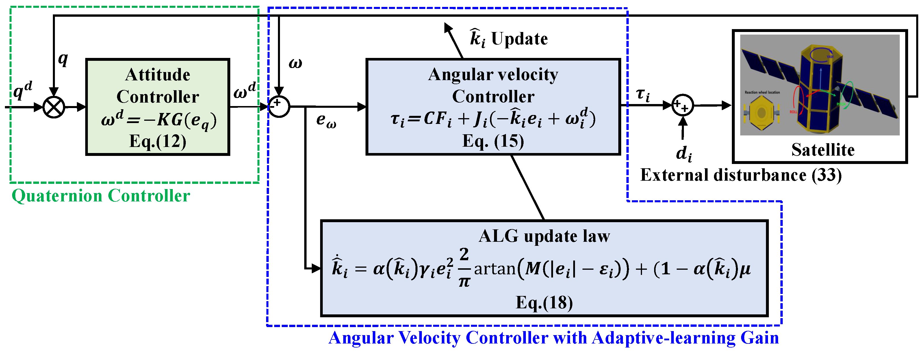
Meanwhile, the nominal inertia used for controller design is given by J p = 55 , J q = 14 , and J r = 49 . The overall simulation structure of the proposed control method is illustrated in Figure 2, where the interaction between the adaptive learning gain, controller, and satellite dynamics is systematically organized. The control system is composed of two main parts: a quaternion-based attitude controller that generates the desired angular velocity and an angular velocity controller with an adaptive learning gain (ALG) mechanism that compensates for time-varying external disturbances. Each component of the control loop is mathematically formulated and explicitly represented in the diagram, including the feedback signals, control torque, and the update law of the learning gain.
Two cases were tested in simulations to evaluate the performance of the proposed controller:
  • Case 1: Conventional controller with fixed gains. This case uses a well-tuned control strategy with fixed and relatively high gain values, which serve as a performance benchmark. The control gains were configured as k p = 400 , k q = 400 , and k r = 400 .
  • Case 2: Proposed ALG-based controller. In this case, the control gains k ^ i ( t ) are adaptively adjusted in real time according to the magnitude of the tracking error. The following parameter settings were used:
    Initial gains: k ^ p ( 0 ) = k ^ q ( 0 ) = k ^ r ( 0 ) = 200 ;
    Learning rates: γ p = 25 , γ q = 15 , γ r = 15 ;
    Slope factor for arctan: M = 10,000 ;
    Desired tracking performance bounds: ε p = ε q = ε r = 0.01 ;
    Minimum gain values: k p   min = k q   min = k r   min = 3 ;
    Residual gain increment: μ = 10 .
The performance of both control cases was evaluated under the presence of unknown time-varying external disturbances acting on all rotational axes. In the simulation, sinusoidal reference trajectories with identical amplitude and frequency were assigned to all three attitude axes (roll, pitch, and yaw), defined as
r i ( t ) = 20 π 180 sin ( 0.15 t + π ) , i = 1 , 2 , 3 .
This setting allows us to evaluate the controller’s tracking performance under coupled multi-axis command signals and time-varying disturbance scenarios. The satellite dynamics were computed using the Simulink Multibody simulation environment. Meanwhile, the control algorithm, including the observer, operated at a discrete sampling interval of 0.01 s. In both simulation scenarios, external disturbances and sensor noise were simultaneously injected into the system. The external disturbances applied to each rotational axis are time-varying and defined over three intervals as follows:
d ( t ) = 10 2 · n ( t ) , for 0 t < 100 s , 0.45 sin ( 2 π t ) + 0.06 0.45 sin ( π t ) + 0.06 0.45 sin ( π t ) + 0.06 + n ( t ) , for 100 t < 200 s , 0.1 sin ( 2 π t ) + 0.01 0.1 sin ( π t ) + 0.01 0.1 sin ( π t ) + 0.01 + n ( t ) , for 200 t 300 s .
Here, n ( t ) = [ n p ( t ) , n q ( t ) , n r ( t ) ] T represents band-limited Gaussian white noise with an effective variance of 9 × 10 5 , applied independently to each rotational axis. The time-varying external disturbances injected in the simulations are shown in Figure 3.
The high-level attitude control law responsible for generating the desired angular velocity was identically implemented in both Case 1 and Case 2. It is given by
ω d = k 1 G ( e q ) z = [ ω p d , ω q d , ω r d ] T ,
where k 1 = diag ( 0.2 , 0.2 , 0.2 ) is a proportional gain matrix, and G ( e q ) is a transformation matrix defined by the unit quaternion error e q and its associated vector part z . This outer-loop controller ensures that the attitude error dynamics are steered toward the origin in both control cases, providing a consistent reference to the inner-loop angular velocity controller.
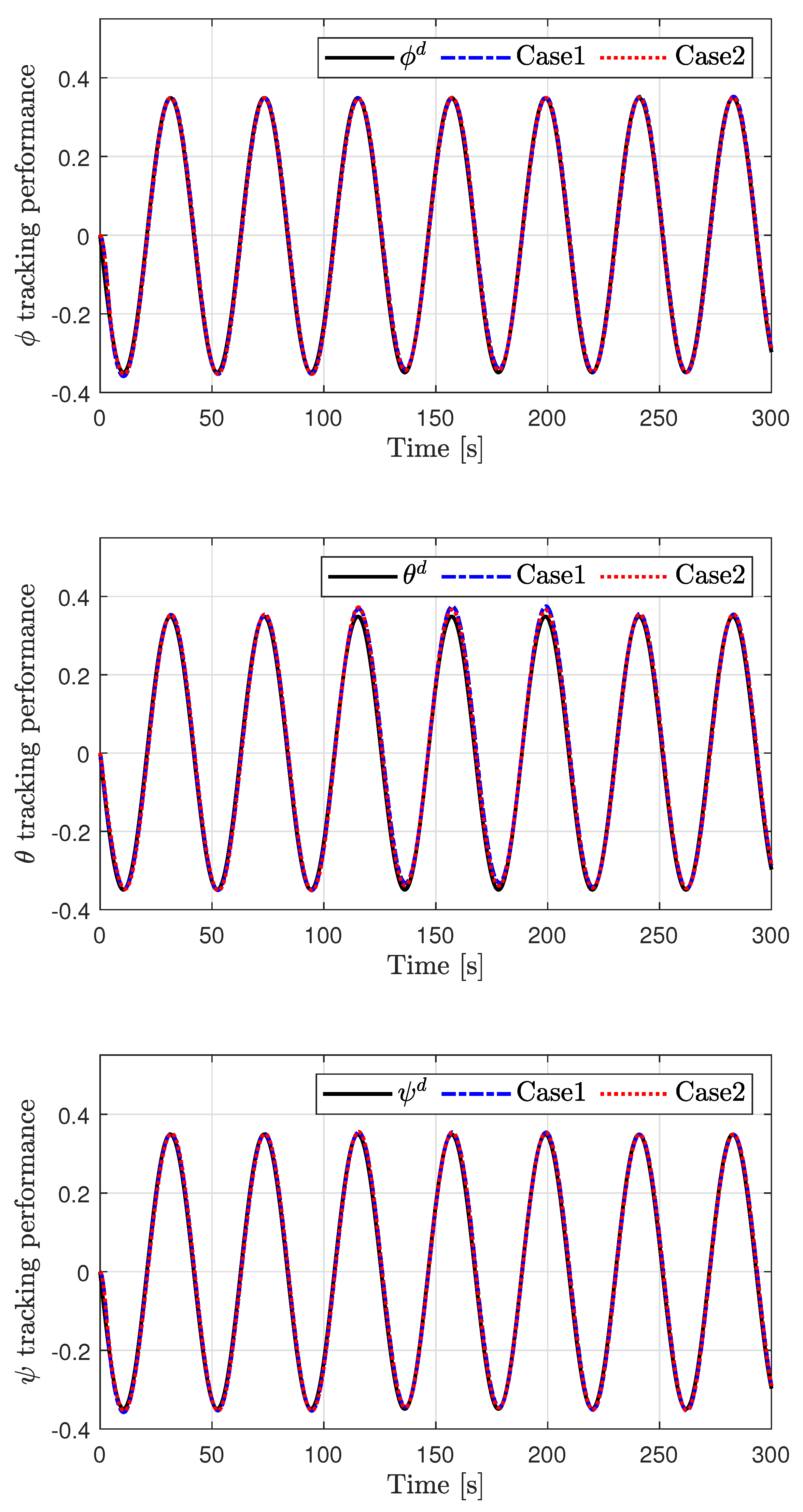
As shown in Figure 4, the attitude tracking performance for both the conventional controller (Case 1) and the proposed ALG-based controller (Case 2) was satisfactory overall. The reference trajectory was accurately followed in both cases, demonstrating that the baseline control performance met the requirements. Table 2 summarizes the RMS tracking errors for e p , e q , and e r across the three simulation scenarios. In all phases, Case 2 consistently achieves lower or comparable tracking errors compared to Case 1. Particularly during the high-disturbance phase ( t = [ 100 , 200 ] ), the proposed controller demonstrates superior robustness, significantly reducing the tracking errors on all three axes. This validates the effectiveness of the ALG in maintaining tight tracking despite disturbance variations.
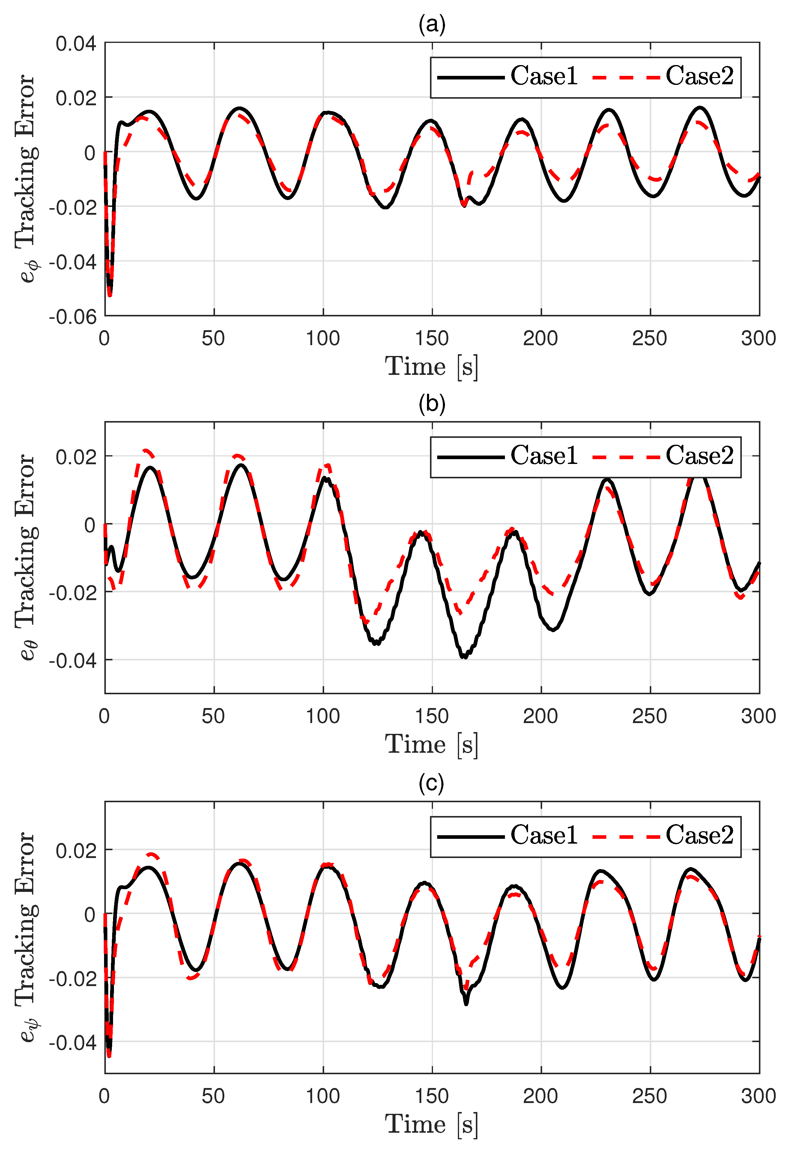
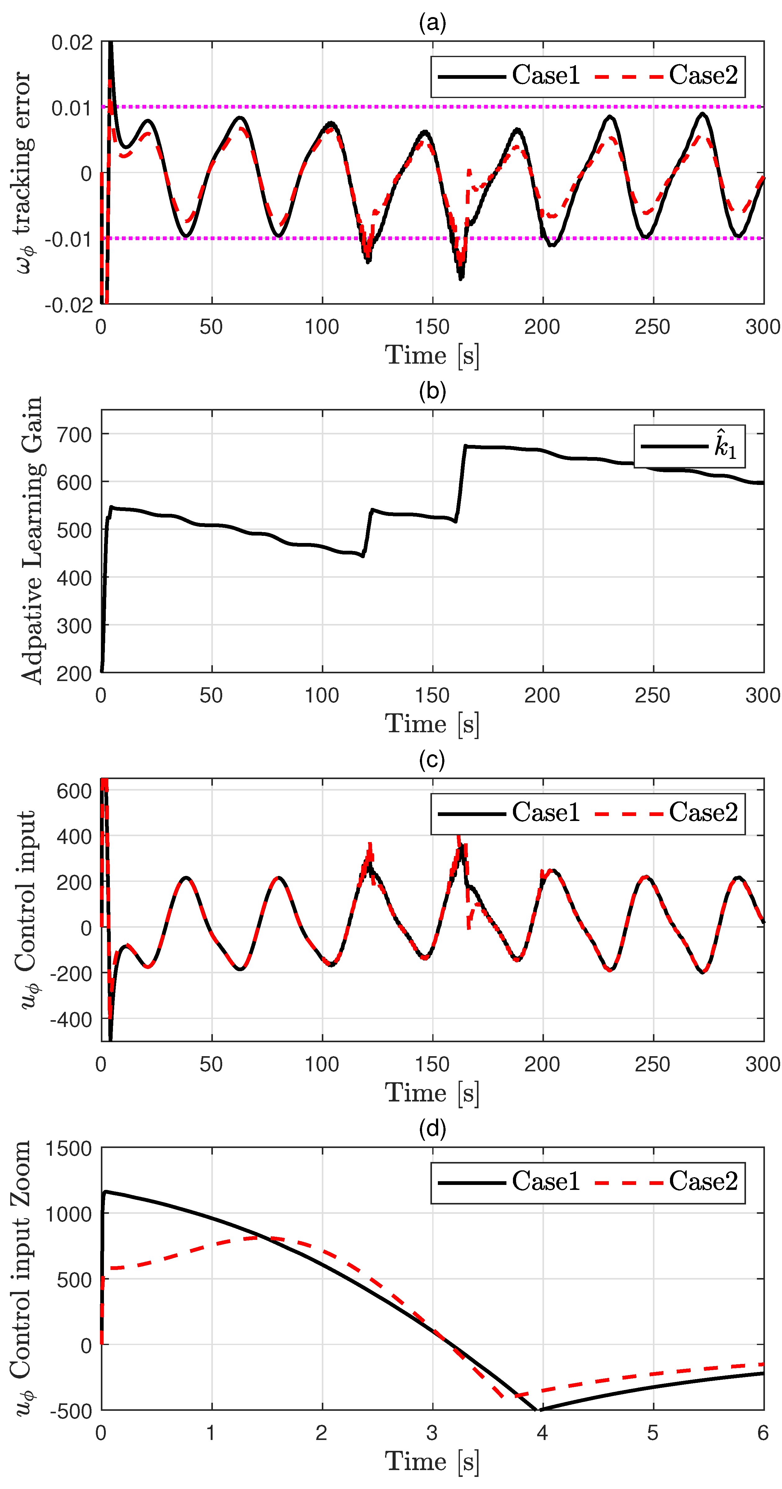
In addition, Figure 5 shows that, especially after 100 s, when large disturbances were injected, Case 2 achieved consistently smaller tracking errors compared to Case 1. To analyze this improvement more closely, Figure 6, Figure 7 and Figure 8 provide detailed views of the internal state and error dynamics. In these figures, the magenta dashed line represents the desired performance bound, ε i , i = [ p , q , r ] , defined earlier in the control design.
The proposed controller (Case 2) effectively constrained the tracking errors within this bound by dynamically adjusting the learning gains. In particular, Figure 7 shows that, between 100 s and 200 s, it can be observed that the system was strongly affected by the external disturbance. Despite having no prior information about this disturbance and without any explicit estimation or compensation process, the estimated gain k ^ 2 increased adaptively to drive the tracking error back into the desired bound. Furthermore, as shown in Figure 7b, when the disturbance subsequently decreased, the controller recognized that the gain was unnecessarily high relative to the error magnitude. Therefore, the ALG autonomously adapted and reduced the gain magnitude to prevent generating excessive control input, which can be observed in Figure 7c. Consequently, the ALG decreased automatically, improving efficiency by reducing control effort without manual retuning. Similar behavior was also consistently observed in Figure 6 and Figure 8. Although the tracking error in Figure 6, Figure 7 and Figure 8 may resemble chattering behavior, the control input remains smooth and continuous. This is because the gain adaptation law uses an arctangent-based function that ensures gradual and bounded updates, and the adaptive gain is applied through integration. Therefore, the observed fluctuations are more likely attributed to strong time-varying sine wave disturbances injected during those intervals.
It is also noteworthy that, in Figure 6, Figure 7 and Figure 8, subfigure (d) consistently shows that the control inputs began with smaller initial values compared to Case 1. The pink dashed line represents the predefined error bound ε i , i [ p , q , r ] used in the control design. Table 3 summarizes the maximum control input required by each axis during Scenario 1, which corresponds to the initial phase of the simulation. This behavior indicates that the proposed method was effective in mitigating the so-called peaking phenomenon, which often arises when large constant gains are applied to ensure robustness. By starting with smaller gains and increasing them only when necessary, the controller suppressed excessive initial transients while maintaining robust tracking. Table 4 reports the average control input magnitudes per axis across all three scenarios. Notably, the proposed method (Case 2) maintains comparable average control effort to the baseline (Case 1) even in the presence of large disturbances ( t = [ 100 , 200 ] ) or when disturbances are reduced ( t = [ 200 , 300 ] ). This indicates that the adaptive learning gain mechanism effectively avoids excessive gain amplification and maintains efficient control regardless of disturbance variations.
Overall, these results confirm that the proposed ALG strategy not only achieves the desired performance bound adaptively but also dynamically balances responsiveness and control efficiency, demonstrating improved tracking accuracy under unknown time-varying disturbances. In addition, the ALG responded rapidly to changes in the disturbance, increasing or decreasing within a short time scale to maintain the desired performance. This capability effectively eliminates the need for extensive gain tuning or manual parameter adjustment, further demonstrating the practical applicability of the proposed method. The simulation video is available at Supplementary Materials https://youtu.be/A8jyAHSF1-Qhttps://youtu.be/A8jyAHSF1-Q (accessed on 16 August 2025).

5. Conclusions

In this paper, an ALG-based attitude control method was proposed to improve the robustness and efficiency of satellite attitude regulation under time-varying external disturbances and model uncertainties. Unlike conventional fixed-gain controllers, the proposed approach dynamically adjusts control gains based on real-time tracking error, ensuring that the error remains within a predefined performance bound without requiring prior knowledge of the disturbance magnitude or extensive gain tuning. The simulation results demonstrate that the proposed controller effectively mitigates the impact of large disturbances while reducing the peaking phenomenon and excessive control inputs often associated with high constant gains. In particular, adaptive gains responded rapidly to changes in disturbance levels, autonomously increasing to suppress large errors and decreasing to maintain efficiency as the errors decreased. The proposed strategy not only achieves reliable tracking performance and robustness against unknown disturbances but also simplifies controller design by eliminating manual parameter adjustments. Future research may extend this approach to more complex satellite models, such as spacecraft equipped with robotic manipulators, experimental validation, and integration with other observer-based disturbance rejection techniques.

Supplementary Materials

The following supporting information can be downloaded at: https://www.mdpi.com/article/10.3390/electronics14163298/s1. A supporting video article is available at https://youtu.be/A8jyAHSF1-Q.

Funding

This research was supported by the Bisa Research Grant of Keimyung University in 2024 (Project No: 20240612).

Data Availability Statement

The data presented in this study are available on request from the corresponding author.

Conflicts of Interest

The authors declare no conflicts of interest.

References

  1. Fajardo, I.; Lidtke, A.A.; Bendoukha, S.A.; Gonzalez-Llorente, J.; Rodríguez, R.; Morales, R.; Faizullin, D.; Matsuoka, M.; Urakami, N.; Kawauchi, R.; et al. Design, Implementation, and Operation of a Small Satellite Mission to Explore the Space Weather Effects in LEO. Aerospace 2019, 6, 108. [Google Scholar] [CrossRef]
  2. Hein, G.W. Status, perspectives and trends of satellite navigation. Satellite Navig. 2020, 1, 22. [Google Scholar] [CrossRef]
  3. Soufi, O.; Belouadha, F.Z. An intelligent deep learning approach to spacecraft attitude control: The case of satellites. J. Franklin Inst. 2024, 361, 107078. [Google Scholar] [CrossRef]
  4. Yang, C.; Fan, Z.; Lu, W.; Gao, H. Uncertain iterative optimal attitude control method for periodic satellite with reliability constraint. IEEE Trans. Aerosp. Electron. Syst. 2024, 60, 6461–6473. [Google Scholar] [CrossRef]
  5. Li, Y.; Ye, D.; Sun, Z. Robust finite time control algorithm for satellite attitude control. Aerospace Sci. Technol. 2017, 68, 46–57. [Google Scholar] [CrossRef]
  6. Hu, Q.; Li, B.; Zhang, Y. Robust attitude control design for spacecraft under assigned velocity and control constraints. ISA Trans. 2013, 52, 480–493. [Google Scholar] [CrossRef]
  7. Wie, B.; Weiss, H.; Arapostathis, A. Quaternion feedback regulator for spacecraft eigenaxis rotations. J. Guid. Control Dyn. 1989, 12, 375–380. [Google Scholar] [CrossRef]
  8. Zhang, Y.; Yang, L.; Cheng, Y.; Ying, K. A performance evaluation approach for satellite attitude control system in tracking mode. Appl. Sci. 2024, 14, 2867. [Google Scholar] [CrossRef]
  9. Jiang, Y.; Hu, Q.; Ma, G. Adaptive backstepping fault-tolerant control for flexible spacecraft with unknown bounded disturbances and actuator failures. ISA Trans. 2010, 49, 57–69. [Google Scholar] [CrossRef] [PubMed]
  10. Hu, J.; Zhang, H.; Wang, Z. Hybrid adaptive control of spacecraft attitude with input saturation and external disturbance. J. Guid. Control Dyn. 2019, 42, 642–649. [Google Scholar] [CrossRef]
  11. Zhou, Y.; Hu, Y.; Ling, K.-V.; Ding, F. Hybrid two-stage identification-based nonlinear MPC strategy for satellite attitude control. IEEE Trans. Aerosp. Electron. Syst. 2025, 61, 1–15. [Google Scholar] [CrossRef]
  12. Zhang, X.; Zong, Q.; Tian, B.; Liu, W. Continuous robust fault-tolerant control and vibration suppression for flexible spacecraft without angular velocity. Int. J. Robust Nonlinear Control 2019, 29, 3915–3935. [Google Scholar] [CrossRef]
  13. Shao, K.; Zheng, J.; Fu, M. Review on the developments of sliding function and adaptive gain in sliding mode control. J. Autom. Intell. 2025. accepted for publication. [Google Scholar] [CrossRef]
  14. Ross, I.M.; Sekhavat, P.; Fleming, A.; Gong, Q. Optimal feedback control: Foundations, examples, and experimental results for a new approach. J. Guid. Control Dyn. 2008, 31, 307–321. [Google Scholar] [CrossRef]
  15. Xiao, B.; Hu, Q.; Zhang, Y. Finite-time attitude tracking of spacecraft with fault-tolerant capability. IEEE Trans. Control Syst. Technol. 2015, 23, 1338–1349. [Google Scholar] [CrossRef]
  16. Li, B.; Hu, Q.; Ma, G. Extended state observer based robust attitude control of spacecraft with input saturation. Aerospace Sci. Technol. 2016, 50, 173–182. [Google Scholar] [CrossRef]
  17. Xiao, Y.; Ye, D.; Sun, Z. Observer-based continuous finite-time attitude control for rigid–flexible coupling satellites. Int. J. Control 2019, 92, 2667–2680. [Google Scholar] [CrossRef]
  18. Zhang, C.; Ma, G.; Sun, Y.; Li, C. Observer-based prescribed performance attitude control for flexible spacecraft with actuator saturation. ISA Trans. 2019, 89, 84–95. [Google Scholar] [CrossRef]
  19. Sun, L.; Zheng, Z. Disturbance-observer-based robust backstepping attitude stabilization of spacecraft under input saturation and measurement uncertainty. IEEE Trans. Ind. Electron. 2017, 64, 7994–8002. [Google Scholar] [CrossRef]
  20. Blanchini, F.; Parisini, T.; Pellegrino, F.A.; Pin, G. High-gain adaptive control: A derivative-based approach. IEEE Trans. Autom. Control 2009, 54, 2164–2169. [Google Scholar] [CrossRef]
  21. Khalil, H.K. High-gain observers in feedback control: Application to permanent magnet synchronous motors. IEEE Control Syst. Mag. 2017, 37, 25–41. [Google Scholar]
  22. Tee, K.P.; Ge, S.S.; Tay, E.H. Barrier Lyapunov functions for the control of output-constrained nonlinear systems. Automatica 2009, 45, 918–927. [Google Scholar] [CrossRef]
  23. Fuentes-Aguilar, R.Q.; Chairez, I. Adaptive tracking control of state constraint systems based on differential neural networks: A barrier Lyapunov function approach. IEEE Trans. Neural Netw. Learn. Syst. 2020, 31, 5390–5401. [Google Scholar] [CrossRef]
  24. Bechlioulis, C.P.; Karras, G.C.; Heshmati-Alamdari, S.; Kyriakopoulos, K.J. Trajectory tracking with prescribed performance for underactuated underwater vehicles under model uncertainties and external disturbances. IEEE Trans. Control Syst. Technol. 2017, 25, 429–440. [Google Scholar] [CrossRef]
  25. Yang, X.; Deng, W.; Yao, J. Neural adaptive dynamic surface asymptotic tracking control of hydraulic manipulators with guaranteed transient performance. IEEE Trans. Neural Netw. Learn. Syst. 2023, 34, 7339–7349. [Google Scholar] [CrossRef]
  26. Yang, X.; Ge, Y.; Zhu, W.; Deng, W.; Zhao, X.; Yao, J. Adaptive motion control for electro-hydraulic servo systems with appointed-time performance. IEEE/ASME Trans. Mechatronics 2024. early access. [Google Scholar] [CrossRef]
  27. Yang, X.; Ge, Y.; Deng, W.; Yao, J. Command filtered adaptive tracking control of nonlinear systems with prescribed performance under time-variant parameters and input delay. Int. J. Robust Nonlinear Control 2023, 33, 2840–2860. [Google Scholar] [CrossRef]
  28. Won, D.; Kim, W.; Shin, D.; Chung, C.C. High-gain disturbance observer-based backstepping control with output tracking error constraint for electro-hydraulic systems. IEEE Trans. Control Syst. Technol. 2015, 23, 787–795. [Google Scholar] [CrossRef]
  29. Jung, J.-W.; Leu, V.Q.; Do, T.D.; Kim, E.-K.; Choi, H.H. Adaptive PID speed control design for permanent magnet synchronous motor drives. IEEE Trans. Power Electron. 2015, 30, 900–908. [Google Scholar] [CrossRef]
  30. Lee, J.Y.; Jin, M.; Chang, P.H. Variable PID gain tuning method using backstepping control with time-delay estimation and nonlinear damping. IEEE Trans. Ind. Electron. 2014, 61, 6975–6985. [Google Scholar] [CrossRef]
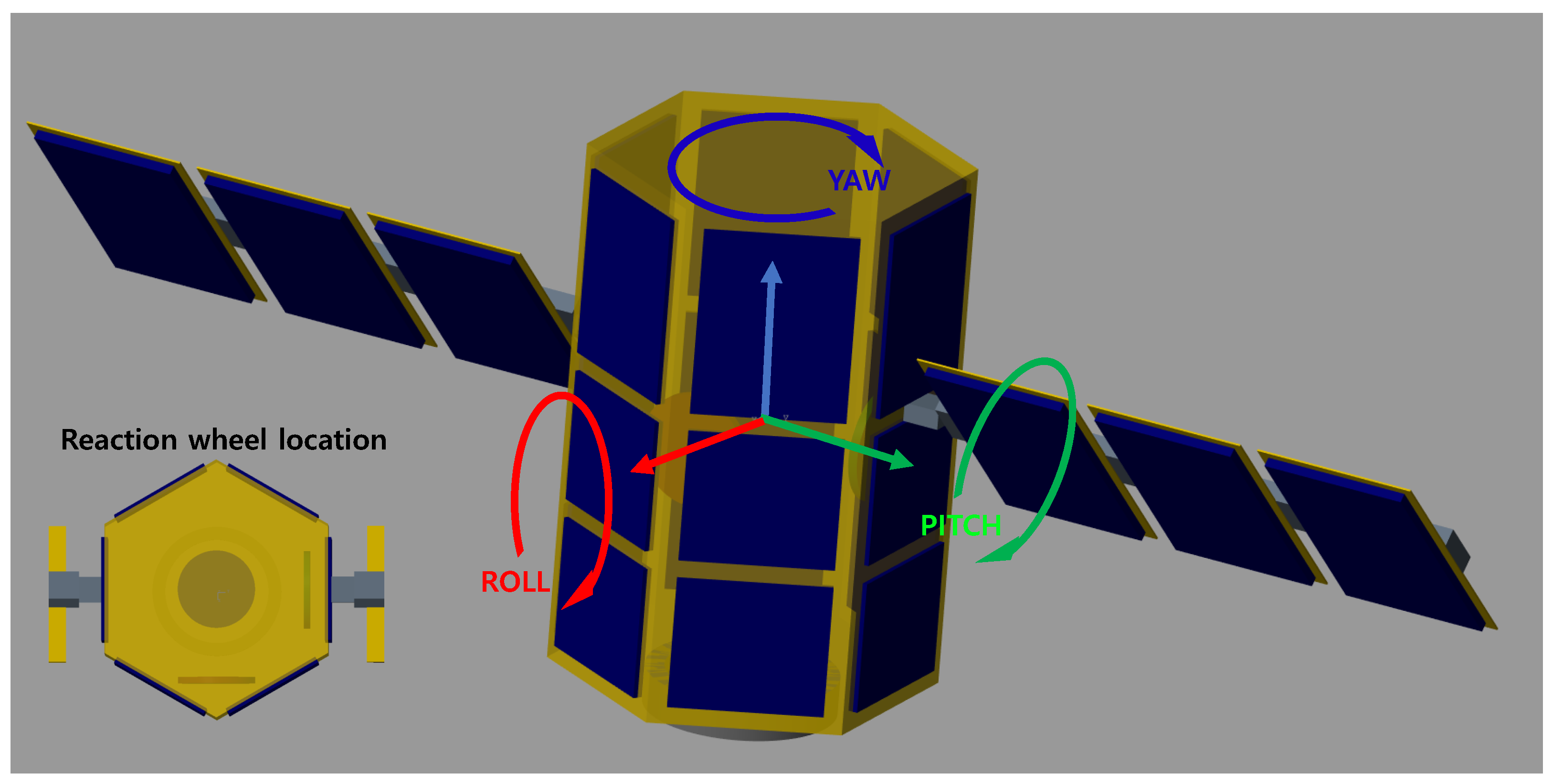
Figure 1. Satellite configuration in MATLAB/Multibody (modify the axis).
Electronics 14 03298 g001
Figure 2. Simulation block diagram of the proposed method.
Electronics 14 03298 g002
Figure 3. Injected disturbance.
Electronics 14 03298 g003
Figure 4. Attitude tracking performance.
Electronics 14 03298 g004
Figure 5. Attitude tracking error. (a) e ϕ tracking error, (b) e θ tracking error, (c) e ψ tracking error.
Electronics 14 03298 g005
Figure 6. ω p tracking performance: (a) tracking error, (b) adaptive learning gain, (c) control input, (d) control input.
Electronics 14 03298 g006
Figure 7. ω q tracking performance: (a) tracking error, (b) adaptive learning gain, (c) control input, (d) control input.
Electronics 14 03298 g007
Figure 8. ω r tracking performance: (a) tracking error, (b) adaptive learning gain, (c) control input, (d) control input.
Electronics 14 03298 g008
Table 1. Satellite parameters.
SymbolDescriptionUnitValue
mMass of the satellite bodykg20
J p Moment of inertia about roll axis (p)kg·m255
J q Moment of inertia about pitch axis (q)kg·m214
J r Moment of inertia about yaw axis (r)kg·m249
I w Moment of inertia of each reaction wheelkg·m20.0029
r w Radius of the reaction wheelm0.18
h w Height of the reaction wheelm0.06
qAttitude quaternion of the satellite--
ω Angular velocity of the satelliterad/s-
ω d Desired angular velocityrad/s-
d i External disturbance torque along axis iNmDefined in Equation (33)
τ i Control torque applied along axis iNmComputed by Equation (15)
T max Maximum torque output of each wheel pairNm1.0
Table 2. Scenario-wise tracking error (RMS) for roll ( e p ), pitch ( e q ), and yaw ( e r ).
ScenarioMethod e p [rad/s] e q [rad/s] e r [rad/s]
1, t = [0, 100]Case 10.02170.00840.0173
Case 20.02040.01140.0167
2, t = [100, 200]Case 10.00560.00760.0055
Case 20.00410.01060.0073
3, t = [200, 300])Case 10.00560.00430.0055
Case 20.00420.00520.0074
Table 3. Maximum control input per axis in Scenario 1 (0–100s).
AxisCase 1 [mNm]Case 2 [mNm]
u p 1161.70811.58
u q 279.40138.41
u r 1008.60503.61
Table 4. Average control input per axis in three scenarios.
ScenarioMethodMean | u p | [mNm]Mean | u q | [mNm]Mean | u r | [mNm]
1, t = [0, 100]Case 1142.7630.80116.44
Case 2135.4230.75105.70
2, t = [100, 200]Case 1121.1354.22106.78
Case 2122.2854.38106.20
3, t = [200, 300]Case 1128.1237.46118.54
Case 2127.1436.61119.53
Disclaimer/Publisher’s Note: The statements, opinions and data contained in all publications are solely those of the individual author(s) and contributor(s) and not of MDPI and/or the editor(s). MDPI and/or the editor(s) disclaim responsibility for any injury to people or property resulting from any ideas, methods, instructions or products referred to in the content.