Article

3D-Printed Circular Horn Antenna with Dielectric Lens for Focused RF Energy Delivery

by
Aviad Michael
and
Nezah Balal
*
Department of Electrical Engineering, Ariel University, Ariel 4076414, Israel
*
Author to whom correspondence should be addressed.
Electronics 2025, 14(16), 3191; https://doi.org/10.3390/electronics14163191
Submission received: 30 June 2025 / Revised: 28 July 2025 / Accepted: 6 August 2025 / Published: 11 August 2025

Abstract

This paper presents the design, simulation, and fabrication of a horn antenna integrated with a dielectric lens for focusing RF energy at 10 GHz. The antenna system combines established electromagnetic principles with 3D printing techniques to produce a cost-effective alternative to commercial focusing antennas. The design methodology employs the lensmaker’s formula and Snell’s law to determine lens curvature for achieving a specified focal length of 100 mm. COMSOL Multiphysics simulations indicate that adding a PTFE lens increases power density concentration compared to a standard horn antenna, with a simulated focal point at approximately 100 mm. Surface roughness analysis based on the Rayleigh criterion supports 3D printing suitability for this application. Experimental validation includes radiation pattern measurements of the antenna without the lens and power density measurements versus distance with the lens, both showing good agreement with simulation results. The measured focal length was 95 ± 5 mm, closely matching simulation predictions. This work presents an approach for implementing focused RF delivery solutions for medical treatments, wireless power transfer, and precision sensing at significantly lower costs than commercial alternatives.

1. Introduction

The manipulation and focusing of electromagnetic waves advance diverse fields including telecommunications, radar systems, medical treatments such as hyperthermia, and wireless power transfer [1,2]. While lens-based focusing techniques are well established in optics, extending these methodologies to radio frequency (RF) waves, particularly in the microwave spectrum, remains an active area with significant practical implications for enhancing precision and efficiency [3,4]. Precise RF energy concentration can improve therapeutic efficacy in medical applications, enhance detection capabilities in radar systems, and increase efficiency in power delivery [5].
Conventional horn antennas are valued for their directional radiation characteristics, relatively high gain, and design simplicity [6,7]. However, these antennas exhibit inherently divergent radiation patterns, especially in their near-field region, limiting their utility for focused energy delivery at specific distances [7,8]. Integrating dielectric lenses presents a practical solution for tailoring wavefronts and enhancing near-field focusing capabilities [9,10].
RF lens design adapts principles from classical optics, including Snell’s law and the lensmaker’s formula [11]. Within the microwave spectrum (1–30 GHz), materials such as polytetrafluoroethylene (PTFE) offer advantages due to their low loss tangents and stable dielectric properties [12,13]. Properly designed dielectric lenses can manipulate electromagnetic wavefront phases to achieve energy convergence at predetermined focal points [14,15].
Commercial focused RF delivery systems, particularly for applications like diathermy and hyperthermia, often utilize proprietary designs with costs exceeding $10,000 [16,17]. This price point restricts accessibility for academic research, education, and smaller-scale industrial applications while typically lacking flexibility for experimental modifications or focal length adjustments [18].
Recent advances in additive manufacturing have transformed RF and microwave component fabrication [19,20,21,22]. 3D printing enables cost-effective creation of complex geometries challenging to produce using conventional methods [23]. When combined with appropriate metallization, 3D-printed structures can yield RF devices with performance comparable to traditionally manufactured counterparts at reduced costs [24,25].
The recent literature demonstrates 3D-printed dielectric lenses achieving 6.9 dB gain improvements with clear cost advantages over conventional machining [26]. However, most published implementations emphasize far-field gain and beam shaping rather than precise near-field focusing at finite distances. Our approach targets controlled focal length with fabrication costs under $500, bridging expensive commercial focusing systems and research prototypes.
This research presents the design, simulation, fabrication, and experimental validation of a circular horn antenna with an integrated dielectric lens operating at 10 GHz. Our approach combines established electromagnetic theory [7] with accessible fabrication techniques—FDM 3D printing for the horn structure and conventional machining for the PTFE lens. The prototype achieves focused RF energy delivery at manufacturing costs under $500, providing an alternative to commercial solutions while maintaining flexibility for focal length customization. This study includes surface roughness analysis relevant to 3D printing, supporting its suitability based on the Rayleigh criterion.
The remainder of this paper is structured as follows: Section 2 presents the theoretical framework and design methodology. Section 3 details simulation setup and results. Section 4 describes the fabrication process. Section 5 outlines experimental validation methodology. Section 6 presents key experimental results. Section 7 discusses overall performance and limitations, and Section 8 concludes with findings and future research directions.

2. Theoretical Framework and Design Methodology

We develop a design for a circular horn antenna integrated with a dielectric lens to focus RF energy at 10 GHz. The proposed system, illustrated in Figure 1, comprises three key components: (1) a circular waveguide exciting the fundamental TE 11 mode, (2) a horn with gradual flare to minimize phase errors across its aperture, and (3) a biconvex dielectric lens (fabricated from PTFE) converting the naturally divergent wavefront into a converging beam. Standard 3D printing resolutions typically satisfy the Rayleigh roughness criterion for the operating wavelength, ensuring surface irregularities do not significantly degrade performance.

2.1. Circular Horn Antenna Design

The antenna begins with a circular waveguide of radius a supporting the TE 11 mode. Its cutoff frequency is:
f c = c χ 11 2 π a ε r ,
where c is the speed of light, χ 11 1.841 is the first zero of the derivative of Bessel function J 1 , and ε r (assumed equal to 1 for air) is the relative permittivity. The free-space wavelength at 10 GHz is:
λ 0 = c f = 30 mm .
Within the waveguide, the guided wavelength is:
λ g = λ 0 1 f c f 2 .
Based on established design principles and simulation optimization, the implemented horn antenna has the following parameters:
  • Waveguide inlet radius: a i n l e t = 11.9125 mm.
  • Circular waveguide length: L w g = 10 mm.
  • Horn flare length: L h o r n = 220 mm.
  • Horn aperture radius: a o u t l e t = 75 mm (aperture diameter = 150 mm, i.e., 5 λ 0 ).
  • Total antenna length: L t o t a l = 230 mm.
  • Operating frequency: f = 10 GHz.
  • Antenna material: metallized 3D-printed structure (modeled as perfect electric conductor).
A gradual flare angle, computed as
ψ = tan 1 a o u t l e t a i n l e t L h o r n 16 ,
ensures minimal phase error across the aperture. This moderate flare angle represents a compromise between directivity and aperture efficiency. The horn directivity can be approximated by:
D 2 π a o u t l e t λ 0 2 η a p ,
where η a p (typically 0.5–0.7) is the aperture efficiency. For our design, we expect approximately 23 dBi directivity.

2.2. Dielectric Lens Design

To enhance horn antenna focusing capability, we designed a dielectric lens based on geometrical optics principles. The lens transforms the divergent wavefront from the horn into a converging wavefront focusing at a predetermined point.
The lens is fabricated from PTFE with material properties adopted from established literature for 10 GHz: relative permittivity ϵ r = 2.2 (refractive index n 2.2 1.483 ) and low loss tangent of approximately 0.0004 [12,13]. The design specifications are:
  • Desired focal length: F = 100 mm.
  • Configuration: symmetrical biconvex lens with 5 mm central gap.
Figure 2 shows the lens geometry.
For a thin lens, the lensmaker’s equation is
1 F = ( n 1 ) 1 R 1 1 R 2 .
For a symmetrical biconvex lens where R 1 = R and R 2 = R , this simplifies to:
1 F = 2 ( n 1 ) R ,
giving the radius of curvature:
R = 2 F ( n 1 ) 2 · 100 mm · ( 1.483 1 ) 96.6 mm .
The surface profile of each convex face is described by the sag equation:
Z ( r ) = R R 2 r 2 ,
which for small r (paraxial approximation) becomes
Z ( r ) r 2 2 R , 0 < r < D 2 .
For a lens with central gap thickness t 0 = 5 mm, the overall thickness profile is:
t ( r ) = t 0 + 2 Z ( r ) = t 0 + 2 R R 2 r 2 .
The phase delay imparted by the lens at radial distance r is:
Δ ϕ ( r ) = k 0 ( n 1 ) t ( r ) ,
with free-space wavenumber k 0 = 2 π / λ 0 .
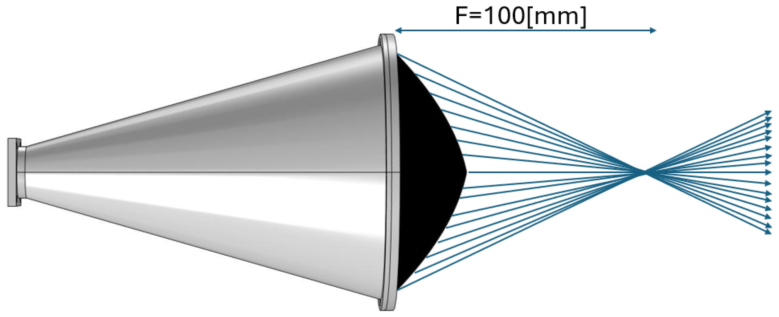
Figure 3 shows the integrated system geometry. While this formula provides a first-order analytical design starting point, final lens optimization was performed using full-wave electromagnetic simulation, which inherently accounts for the horn’s specific wavefront characteristics and associated phase variations.

2.3. Surface Roughness Considerations

Surface quality of both the metallized horn and PTFE lens is crucial for maintaining electromagnetic performance, particularly when using additive manufacturing. The Rayleigh roughness criterion states that root-mean-square (RMS) surface roughness σ should satisfy
σ < λ 0 8
for normal incidence. At 10 GHz ( λ 0 = 30 mm), this requires σ < 3.75 mm, and even the more stringent criterion of λ 0 / 32 ( σ < 0.94 mm) is easily met by conventional 3D-printing processes.
In our implementation, both the metallized surface of the 3D-printed horn and machined PTFE lens exhibit σ < 0.5 mm, ensuring surface roughness does not adversely affect system performance. This analysis suggests modern 3D-printing technologies provide sufficient surface quality for microwave applications at X-band frequencies and below.

3. Simulation Methodology and Results

3.1. Simulation Setup

The electromagnetic performance was numerically analyzed using COMSOL Multiphysics 6.2 (COMSOL AB, Stockholm, Sweden) and CST Studio Suite 2024 (Dassault Systèmes, Vélizy-Villacoublay, France). This dual-simulation approach provided cross-validation and increased confidence in computational outcomes. Both simulations were configured for 10 GHz operation with antenna and lens geometries as specified in Section 2.
Simulation domains were configured with:
  • Excitation: TE 11 mode at waveguide input port.
  • Boundary conditions: Perfect Electric Conductor (PEC) for antenna surfaces.
  • External boundaries: Perfectly Matched Layers (PML) to eliminate reflections.
  • Mesh resolution: minimum λ / 10 element size in critical regions.
  • Dielectric properties: PTFE with ε r = 2.2 and loss tangent tan δ = 0.0004 .
To assess dielectric lens focusing capability, all simulations were performed in pairs: one with horn antenna alone, another with horn antenna coupled to the biconvex PTFE lens. This approach enabled direct quantification of the lens’s contribution to system performance.

3.2. Electric Field Distribution

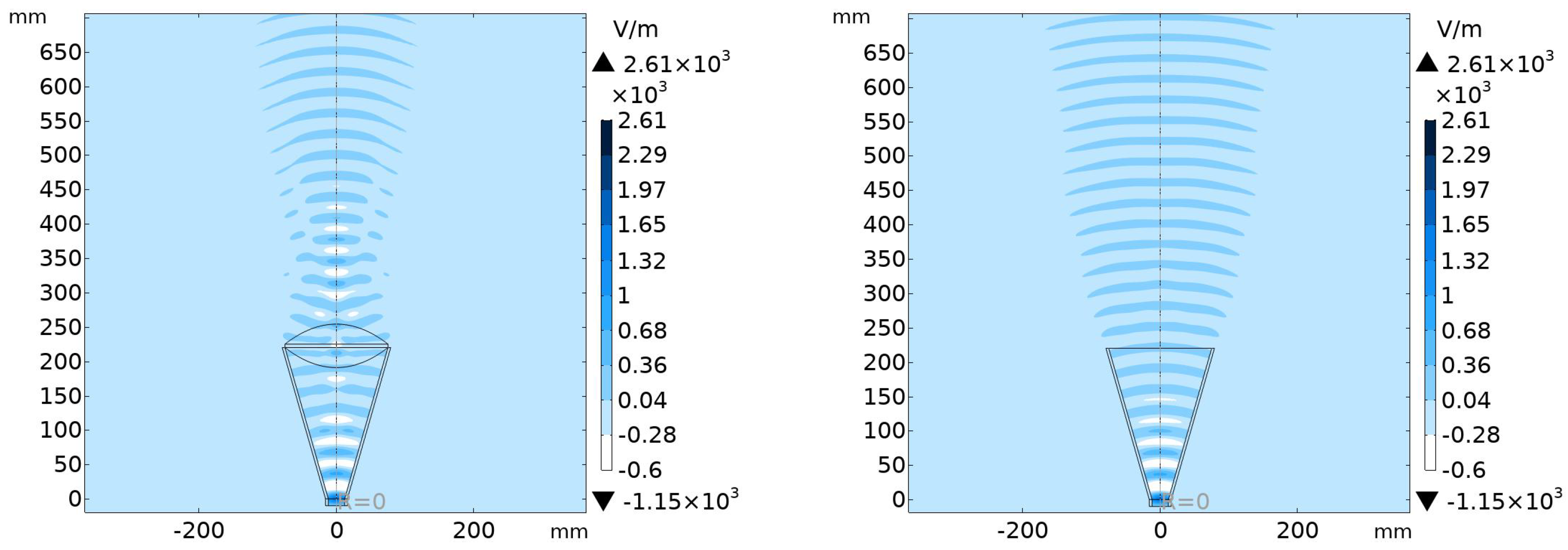
Figure 4 presents simulated electric field magnitude distribution in the x z -plane for both configurations. Figure 4 Right shows the expected divergent pattern for the horn antenna without lens, where field strength diminishes with increasing distance from the aperture. In contrast, Figure 4 Left demonstrates the focusing effect when the dielectric lens is introduced. Field lines converge towards the designed focal point, situated approximately 100 mm from the lens surface, with peak field strength notably higher compared to the lens-free setup at the same location.
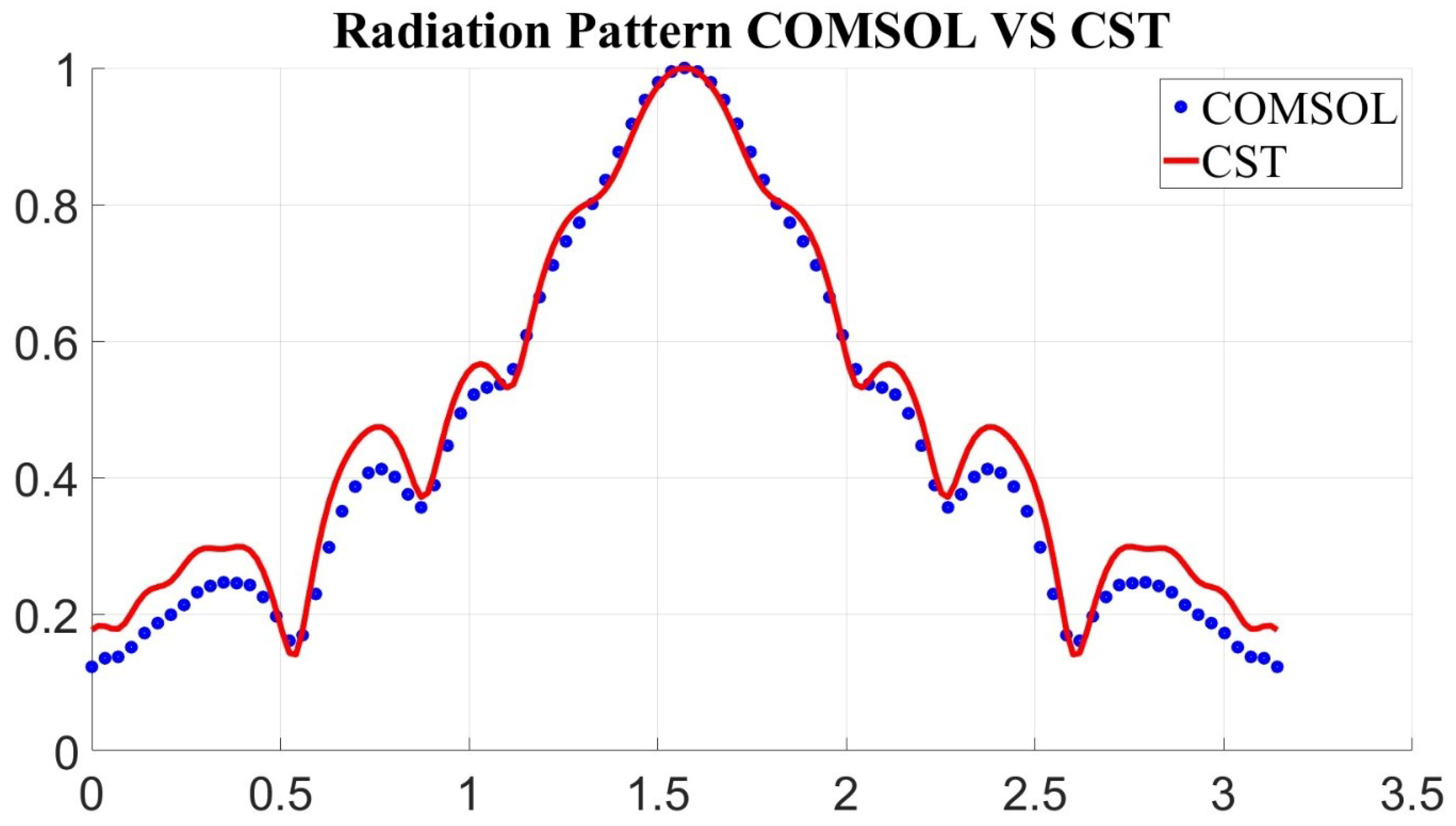
Cross-validation of our computational approach is demonstrated in Figure 5, comparing far-field radiation patterns from COMSOL Multiphysics and CST Studio Suite for the horn antenna without lens. Excellent agreement between simulation tools validates our computational methodology and confirms reliability of subsequent results. Both simulations show the expected symmetrical main beam with moderate directivity and characteristic side lobes.
Adding the dielectric lens significantly alters these radiation characteristics. While the far-field pattern still shows a main lobe and side lobes, the near-field behavior undergoes substantial transformation. The lens converts the spherical wavefront emanating from the horn into a converging wavefront, effectively concentrating energy at the focal point before diverging again in the far field.

3.3. Power Density Distribution

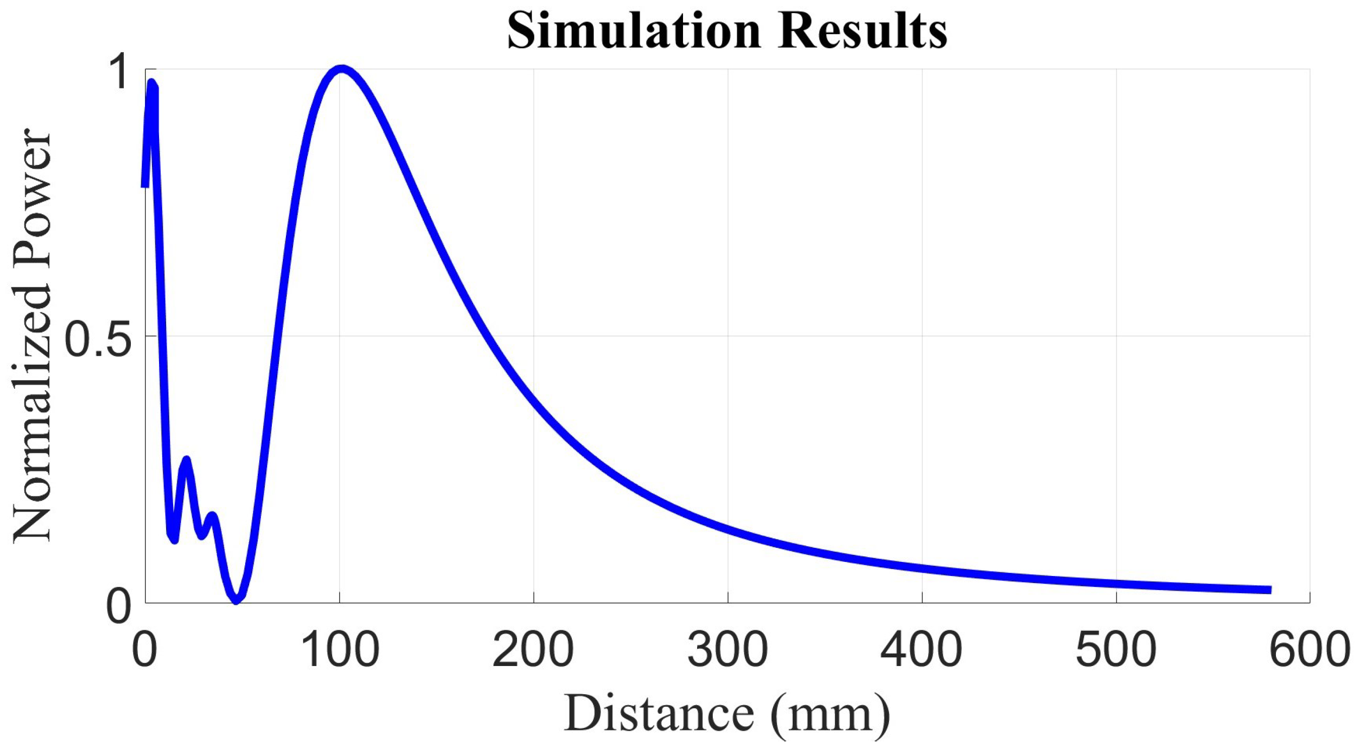
Focusing capability is indicated by power density distribution along the central propagation axis (z-axis). Figure 6 depicts simulated power density versus distance from antenna aperture for the horn antenna with lens. Power density initially decreases slightly from the aperture but then rises sharply to a distinct peak of approximately 950 W/m2 at the focal point, before decreasing at further distances. This peak represents significant energy concentration compared to the unfocused field without the lens; the calculated focusing gain (ratio of peak power density with lens to power density without lens at focal distance) is approximately 3.5.
Two-dimensional power density distribution in the x z -plane at focal distance ( z 100 mm) is shown in Figure 7. Without the lens (Figure 7b), power density exhibits a broad, Gaussian-like distribution. With the lens (Figure 7a), there is a defined focal spot with higher intensity and smaller spatial extent.

3.4. Focal Performance Validation

The simulated focal length was measured by finding peak power density location along the axis in Figure 6. It was found to be 100 ± 0.5 mm from the antenna outlet, in good agreement with the designed value of 100 mm. This small discrepancy (around 0.5%) is within expected limits, considering inherent discretization in numerical simulations and approximations in lens design equations (Section 2.2).
The focal spot size, defined as Full Width at Half Maximum (FWHM) of power density distribution in the focal plane, was approximately 0.8 λ 0 = 24 mm. This value is consistent with the theoretical diffraction limit for the given lens diameter and focal length.

4. Fabrication Process

4.1. Antenna Fabrication

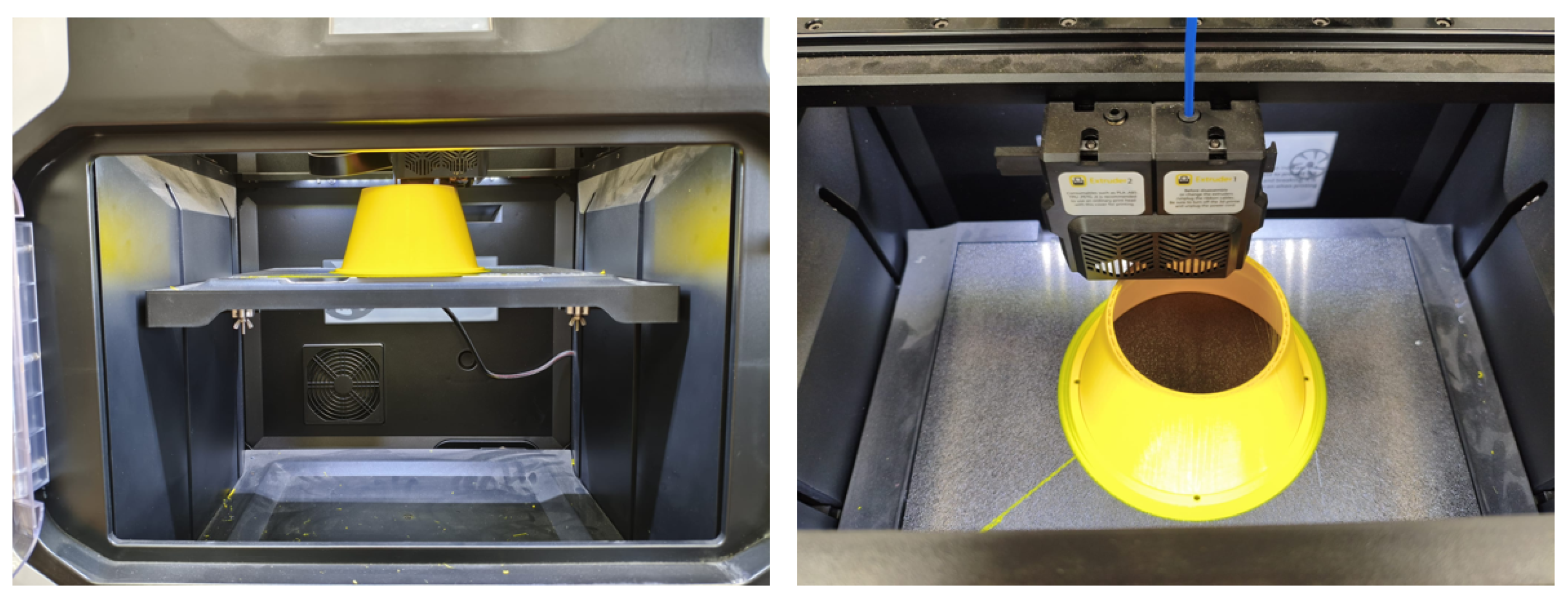
The horn antenna was fabricated using 3D printing with Acrylonitrile Butadiene Styrene (ABS) filament to achieve adequate mechanical strength and temperature resistance. The printing process (illustrated in Figure 8) used a Qidi i Fast 3D printer (Qidi Technology, Zhejiang, China) utilizing Fused Deposition Modeling (FDM) technology, where ABS filament is melted and extruded layer by layer. Printing parameters including layer height, infill density, and printing speed were optimized to balance printing time and structural integrity.
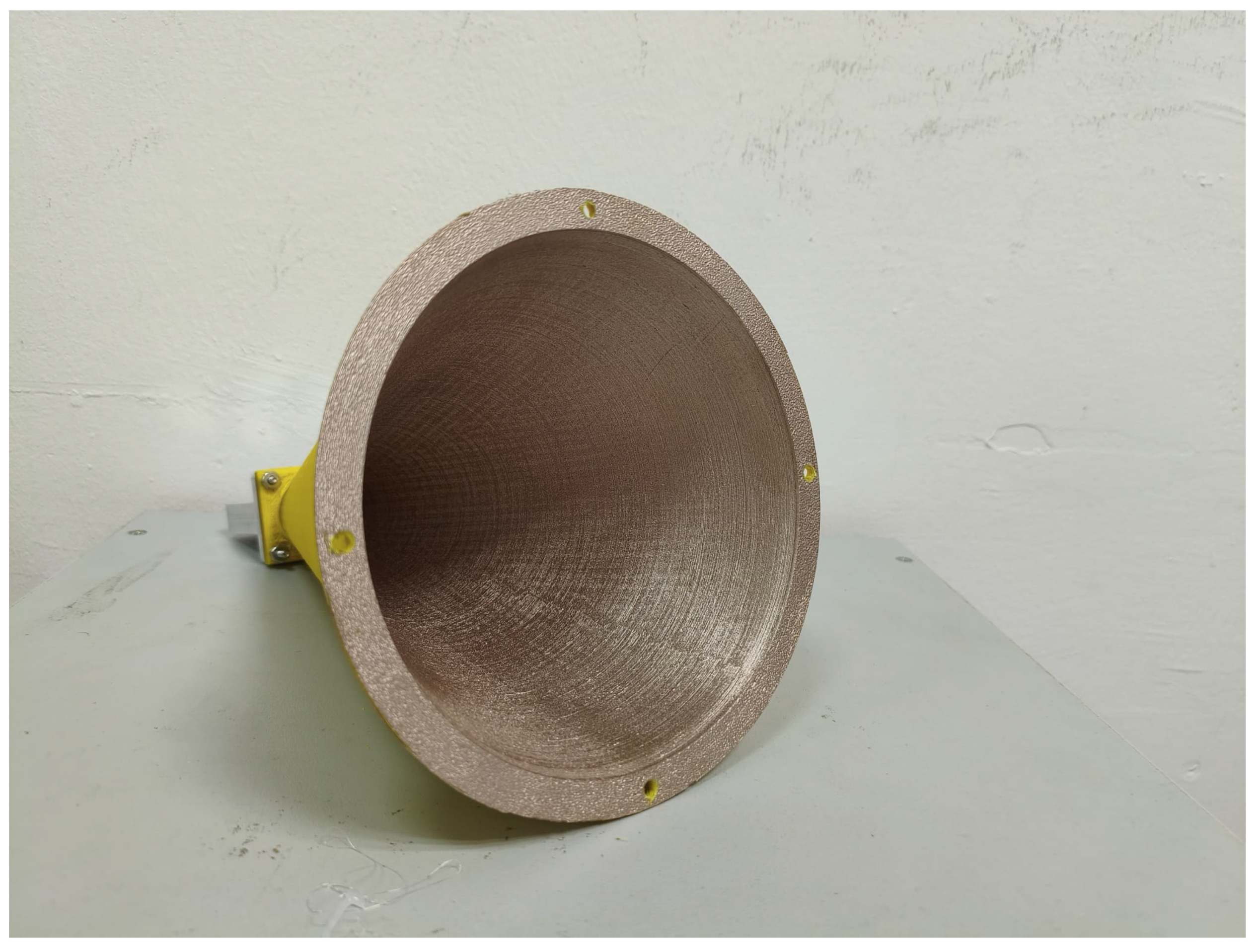
Figure 9 shows the antenna structure prior to metallization. Following printing, the antenna underwent metallization using conductive copper-based spray paint (Conductive Coating Pro). This coating, designed for plastic substrates including ABS, provides an effective conductive layer with thickness less than 25 μ m (1.0 mil). Surface resistance of the applied coating was measured as less than 0.015 Ω / , ensuring suitable conductivity for microwave operation. Light sanding was applied prior to coating application to improve adhesion and surface uniformity.

4.2. Dielectric Lens Fabrication

The dielectric lens was fabricated based on a Computer-Aided Design (CAD) model developed in SOLIDWORKS 2023 (Dassault Systèmes, Vélizy-Villacoublay, France), subsequently translated into machine code for Computer Numerical Control (CNC) milling. Milling operations were performed on a solid cylindrical PTFE block. The biconvex profile, with dimensions specified in Section 2.2, was achieved by machining each convex surface independently. A milling resolution of 0.2 mm ensured adequate surface finish for electromagnetic performance.
Given the lens geometry, a custom aluminum fixture (Figure 10) was fabricated to provide precise and stable positioning of the first milled convex surface during machining of the opposing side. The resulting surface finish was sufficient for target electromagnetic performance, obviating additional polishing or surface treatment. Figure 11 presents the finalized biconvex PTFE lens.

4.3. Assembly

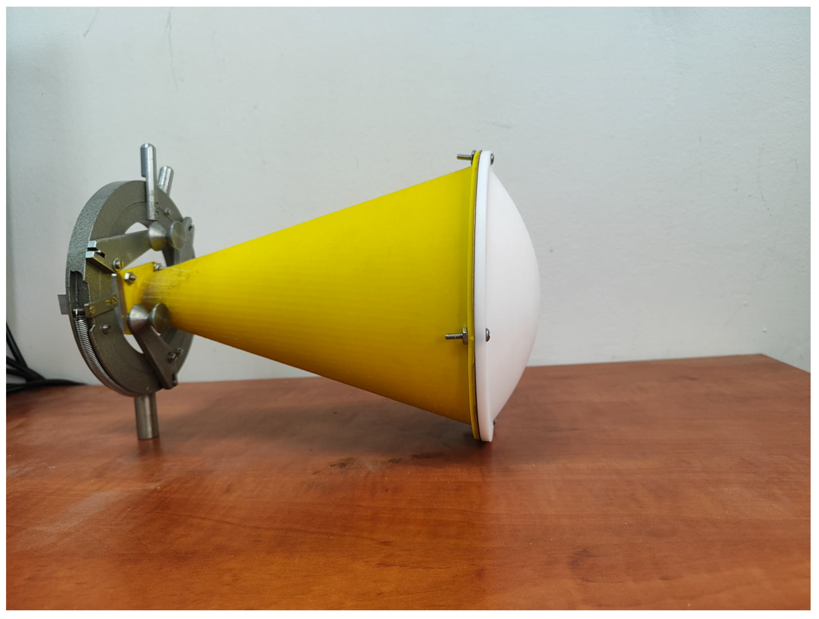
Integration of the dielectric lens with the horn antenna was achieved through a mechanical interlocking mechanism designed directly into the 3D-printed antenna structure and machined lens. The antenna design incorporated precisely located grooves and holes corresponding to matching features on the lens. The lens featured holes aligned with those on the antenna, allowing secure fastening using screws. This method ensured stable and repeatable alignment between antenna and lens, crucial for maintaining desired focusing characteristics. Figure 12 depicts the final assembled prototype.

4.4. Quality Control

Throughout fabrication, basic dimensional measurements verified adherence of the printed antenna and machined lens to design specifications. Calipers and measuring tools checked critical dimensions. Furthermore, fabricated antenna–lens system performance was evaluated through subsequent power measurements (Section 6), providing indirect assessment of fabrication accuracy and quality.

5. Experimental Validation

Experimental validation was divided into two primary procedures: power density measurement as a function of distance and radiation pattern characterization.

5.1. Power Density Measurement as a Function of Distance

The experimental setup used a Continuous Wave (CW) signal source at 10 GHz, with a standard microwave signal generator connected to the transmitting horn antenna (the fabricated and metallized antenna described in Section 4). Transmitted power was controlled and maintained constant throughout the experiment.
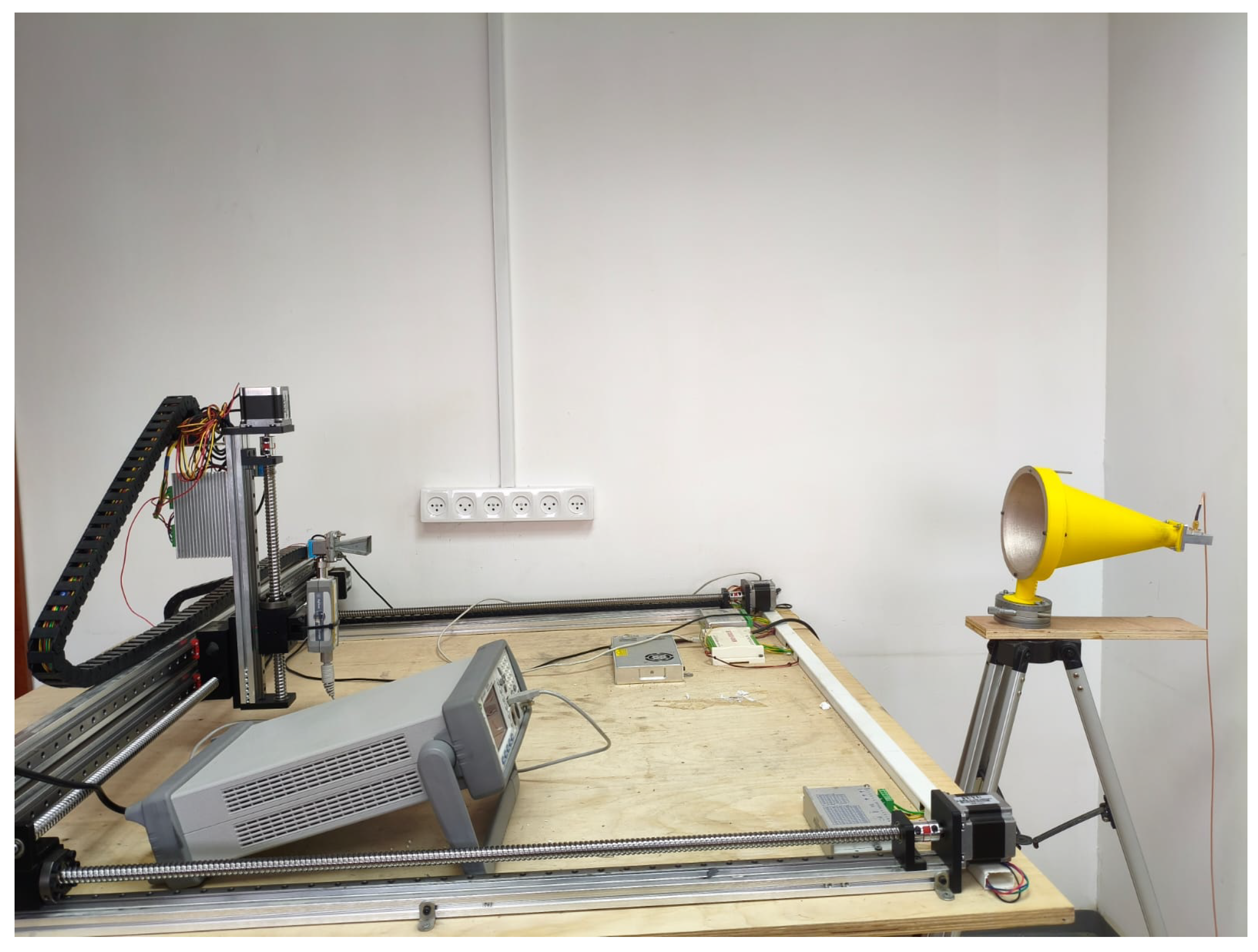
The receiving antenna, identical to the transmitting one, was mounted on a precision XYZ motorized positioning system (model XYZ Linear Stage) with 5 mm resolution incremental movements. The receiving antenna was aligned coaxially with the transmitting antenna and moved along the propagation axis (z-axis) to measure received power versus distance. Power levels were recorded using a calibrated power meter (Keysight N1914A, Keysight Technologies, Santa Rosa, CA, USA) connected directly to the receiving antenna through low-loss coaxial cable. Measurements were conducted in 5 mm incremental steps, covering a range sufficient to capture power density variation near the designed focal point (approximately 100 mm). Figure 13 shows the overall setup.
Collected power data was normalized relative to maximum recorded power to facilitate direct comparison with COMSOL Multiphysics simulation results. This normalization allowed experimental data to be plotted alongside simulated results (presented in Section 6), illustrating correlation between measurement and simulation for lens focusing performance.

5.2. Radiation Pattern Measurement

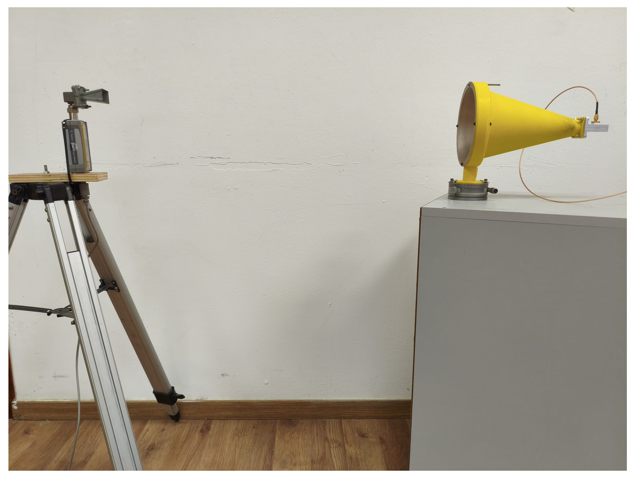
Radiation pattern measurements characterized the antenna’s directional properties, primarily without the dielectric lens for comparison with standard horn theory and simulations. This procedure employed an optical actuator (Thorlabs rotation stage, Thorlabs Inc., Newton, NJ, USA) providing angular control with 0.5 accuracy. The transmitting antenna was fixed at a stationary position, continuously emitting a CW signal at 10 GHz. Figure 14 shows the general setup.
The receiving horn antenna was mounted on the optical actuator at a fixed distance of 2.5 m from the transmitting antenna. This distance satisfies the far-field criterion 2 D 2 λ , where D is antenna aperture diameter and λ is wavelength. For our system with D = 150 mm and λ = 30 mm at 10 GHz, the minimum far-field distance is:
d far-field = 2 D 2 λ = 2 × ( 0.15 ) 2 0.03 = 1.5 m
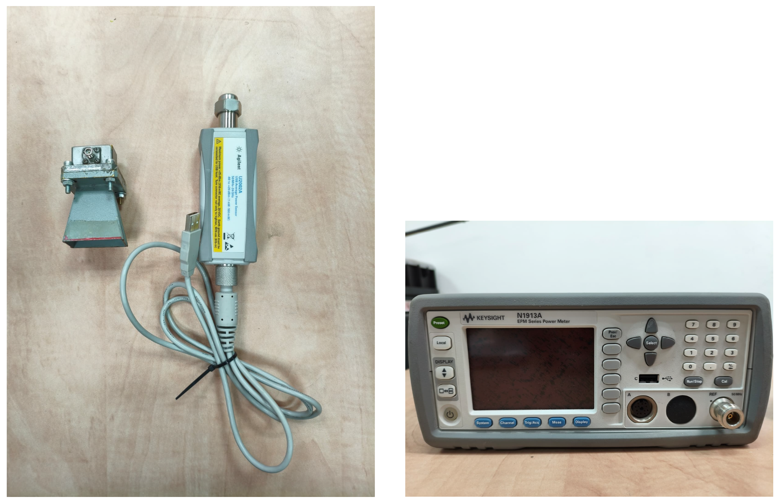
The chosen measurement distance of 2.5 m provides an adequate safety margin, ensuring valid far-field radiation pattern measurements. The receiver was rotated incrementally in 0.5 angular steps, with received power recorded at each position by the same calibrated Keysight N1914A power meter. Figure 15 shows key measurement receiver setup components.
The measured angular power distribution was normalized to maximum power reading, producing a relative radiation pattern for direct comparison with simulated radiation patterns (results in Section 6).

6. Experimental Results

This section presents key experimental results from measurements described in Section 5, focusing on the radiation pattern of the baseline horn antenna and axial power density distribution of the antenna integrated with the dielectric lens.

6.1. Radiation Pattern Measurement Results

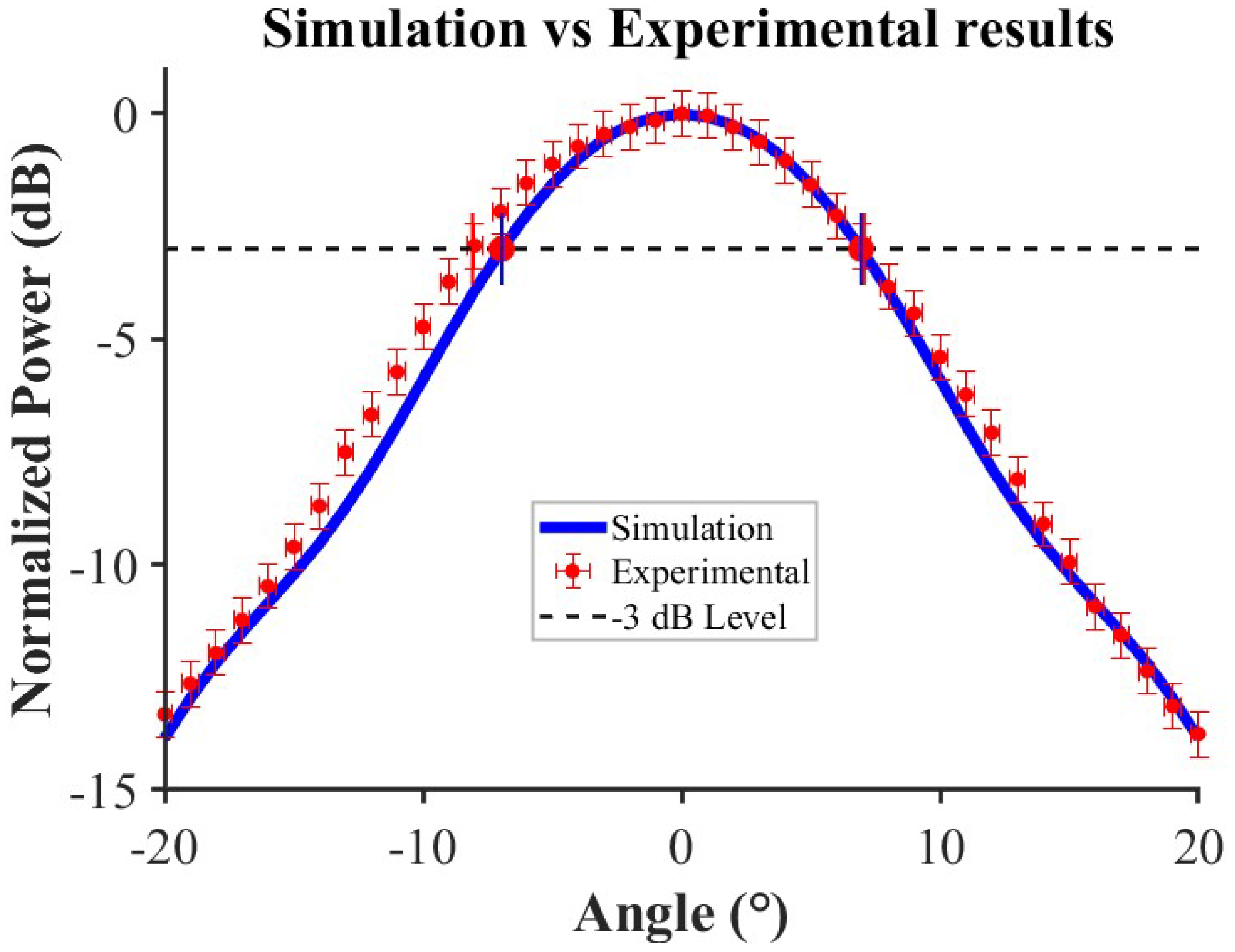
The far-field radiation pattern of the fabricated horn antenna without dielectric lens was measured to characterize baseline performance and compare with the simulation model. Figure 16 presents the comparison between measured normalized power (in dB) versus angle and corresponding COMSOL simulation result.
Good agreement exists between measured data points (red markers with error bars) and the simulated pattern (blue solid line), particularly within the main lobe. The measured Half-Power Beamwidth (HPBW), defined as the angular width where power drops 3 dB from peak, is approximately 16 (from 8 to + 8 ), consistent with simulation predictions. This result supports the fabrication and metallization process and validates the electromagnetic simulation model.

6.2. Axial Power Density Measurement Results

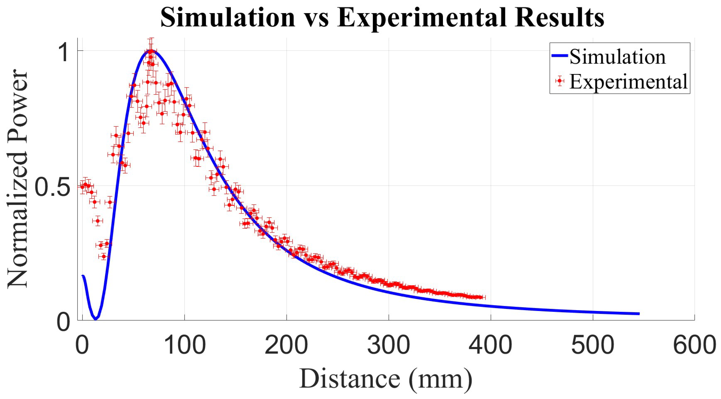
The core experiment measured power density along the central propagation axis (z-axis) for the horn antenna integrated with the fabricated PTFE dielectric lens to evaluate focusing capability. Figure 17 shows measured normalized power versus distance (mm) from antenna aperture, compared with simulated results.
Experimental results demonstrate the predicted focusing effect. Measured power density (red markers with error bars) increases from the initial near-field region, reaches a distinct peak, then decreases at further distances. Peak power density, indicating the focal region, was experimentally observed at approximately 95 ± 5 mm from the antenna aperture. This measured focal length agrees well with the simulated value of 100 mm. The comparison shows reasonable agreement in overall power density profile shape, including decay beyond the focal region.

6.3. Input Impedance Performance (S11)

Input reflection characteristics (S11) of the fabricated antenna system were evaluated to assess impedance matching performance across 8–12 GHz. Figure 18 presents the comprehensive comparison between simulation and measurement results for both antenna configurations.
Figure 18a presents S11 comparison for the complete antenna–lens system. Integrating the dielectric lens introduces some frequency-dependent variations in input impedance characteristics. However, measured results show reasonable correlation with simulation predictions, and the system maintains S11 values better than 15 dB at 10 GHz design frequency. Throughout the analyzed frequency range, both configurations consistently achieve return loss values superior to 10 dB, confirming adequate input matching for the intended RF focusing application.
Figure 18b shows S11 performance for the horn antenna without dielectric lens. Measured S11 demonstrates excellent agreement with simulated values, particularly around 10 GHz where both achieve return loss better than 25 dB. Across the entire frequency band, both simulation and measurement consistently show S11 values better than 10 dB, indicating good impedance matching.
Close agreement between simulated and measured S11 results validates both the electromagnetic modeling approach and fabrication quality of the prototype antenna system.

7. Discussion

7.1. Validation of Baseline Horn Antenna

Characterization of the horn antenna without lens indicated baseline performance. The measured radiation pattern (Figure 16) shows good agreement with simulations, exhibiting a symmetrical main lobe with an approximate Half-Power Beamwidth (HPBW) of 16 , consistent with 23 dBi expected directivity. This agreement supports the electromagnetic model and fabrication/metallization process.

7.2. Focusing Performance with Dielectric Lens

Integration of the dielectric lens achieved RF energy focusing consistent with design goals. Comparison between simulated and measured normalized power density along the propagation axis (Figure 17) shows good focal length agreement. The measured focal point around 95 ± 5 mm aligns well with the simulated prediction of 100 mm, supporting the validity of the lens design methodology and simulation model.
Measured results demonstrate the lens’s ability to concentrate power, exhibiting a distinct peak higher than the horn alone would produce at that distance. Some discrepancies in peak power level ratio or decay shape beyond focus may be attributed to variations in material properties ( ε r of PTFE), fabrication tolerances in lens curvature or horn structure, measurement uncertainties (alignment, scattering), or simulation model limitations (e.g., Perfect Electric Conductor assumption). Nevertheless, focal length agreement supports overall validation of the focusing principle.

7.3. Manufacturing and Cost Considerations

This study demonstrated fabrication of a functional focusing system using cost-effective FDM 3D printing and conventional PTFE machining, followed by spray metallization. Utilizing readily available materials and processes achieved cost reduction compared to commercial systems while retaining design flexibility. The combination of quality checks and demonstrated focusing performance, particularly accurate focal length achievement, supports the viability of this hybrid approach for producing functional prototypes.

7.4. Limitations and Future Work

While the primary goal of achieving accurate focal length was met, certain limitations remain. Current experiments focused on axial power density and the baseline horn radiation pattern. More comprehensive characterization could include detailed 2D focal spot measurements and radiation pattern characterization with lens in place. Additionally, observed discrepancies between simulation and measurement warrant further investigation. Future efforts could focus on refining fabrication tolerances, exploring alternative materials or lens designs (e.g., different focal lengths or frequencies), and characterizing system performance across wider frequency bands or for specific target applications.

8. Conclusions

This paper presented a methodical approach for design, simulation, fabrication, and validation of a circular horn antenna integrated with a biconvex dielectric lens for focused RF energy delivery at 10 GHz. By combining electromagnetic principles with FDM 3D printing for the horn structure and conventional machining for the PTFE lens, we developed a focusing system with manufacturing costs under $500, offering an alternative to expensive commercial solutions.
Simulation results indicated a 3.5-fold increase in peak power density at the focal point compared to horn antenna alone, with a predicted focal length of 100 mm. Experimental measurements demonstrated focusing capability with a measured focal length of 95 ± 5 mm, showing good agreement with simulation predictions. Radiation pattern measurements of the fabricated horn antenna without lens demonstrated consistency with simulation models, supporting baseline antenna performance evaluation.
Observed discrepancies between measured and simulated power density profiles provide direction for future research. These differences likely result from measurement uncertainties, fabrication tolerances, and simulation model limitations.
This approach offers a practical solution for applications requiring localized RF power delivery in medical treatments, wireless power transfer, and specialized sensing, particularly in resource-constrained research and educational settings. Future work could explore comprehensive 2D focal spot characterization, investigate alternative lens designs for different focal properties, and optimize the system for specific frequency bands or applications.

Author Contributions

Conceptualization, N.B.; methodology, N.B.; software, A.M.; validation, A.M. and N.B.; formal analysis, N.B.; investigation, A.M. and N.B.; resources, N.B.; data curation, A.M.; writing—original draft preparation, N.B.; writing—review and editing, N.B.; visualization, A.M.; supervision, N.B.; project administration, N.B.; funding acquisition, N.B. All authors have read and agreed to the published version of the manuscript.

Funding

This research received no external funding.

Data Availability Statement

Data is contained within the article.

Acknowledgments

We thank Moshe Klein for his significant contributions to this research, including technical expertise in experimental setup, assistance with measurements, and valuable feedback throughout development of the measurement system. The authors acknowledge the use of the AI tool Claude (Anthropic) for assistance with English language editing, formatting, and preparing the manuscript in accordance with the publisher’s template. The tool had no role in the scientific content, data analysis, or conclusions of the study.

Conflicts of Interest

The authors declare no conflicts of interest.

References

  1. Zhou, Y.; Liu, C.; Huang, Y. Wireless power transfer for implanted medical application: A review. Energies 2020, 13, 2837. [Google Scholar] [CrossRef]
  2. Khan, A.N.; Cha, Y.O.; Giddens, H.; Hao, Y. Recent advances in organ specific wireless bioelectronic devices: Perspective on biotelemetry and power transfer using antenna systems. Engineering 2022, 11, 50–63. [Google Scholar] [CrossRef]
  3. Nisamol, T.A.; Ansha, K.K.; Abdulla, P. Design of Sub-THz beam scanning antenna using Luneburg lens for 5G communications OR beyond. Prog. Electromagn. Res. C 2020, 99, 179–191. [Google Scholar] [CrossRef]
  4. Bor, J.; Lafond, O.; Merlet, H.; Le Bars, P.; Himdi, M. Foam based Luneburg lens antenna at 60 GHz. Prog. Electromagn. Res. Lett. 2014, 44, 1–7. [Google Scholar] [CrossRef]
  5. Khan, A.N.; Ermakov, A.; Sukhorukov, G. Radio frequency controlled wireless drug delivery devices. Appl. Phys. Rev. 2019, 6, 041301. [Google Scholar] [CrossRef]
  6. Balanis, C.A. Antenna Theory: Analysis and Design, 4th ed.; Wiley: Hoboken, NJ, USA, 2016. [Google Scholar]
  7. Wang, C.; Wu, J.; Guo, Y.-X. A 3-D-printed wideband circularly polarized parallel-plate Luneburg lens antenna. IEEE Trans. Antennas Propag. 2020, 68, 4944–4949. [Google Scholar] [CrossRef]
  8. Rodríguez Pino, M.; González Ayestarán, R.; Nepa, P.; Manara, G. An overview on synthesis techniques for near-field focused antennas. In Wireless Power Transfer Technologies and Applications; IntechOpen: London, UK, 2019. [Google Scholar]
  9. Sivakumar, R.; Azemi, S.N.; Lee, Y.S.; Kok, Y.Y.; Soh, P.J. 3-D Printed Antennas with Dielectric Lens for Free-Space Constitutive Parameters Measurement. Semarak Int. J. Electron. Syst. Eng. 2024, 1, 1–25. [Google Scholar] [CrossRef]
  10. Goulas, A.; Zhang, S.; McGhee, J.R.; Cadman, D.A. Fused filament fabrication of functionally graded polymer composites with variable relative permittivity for microwave devices. Mater. Des. 2020, 191, 108635. [Google Scholar] [CrossRef]
  11. Helena, D.; Ramos, A.; Varum, T.; Matos, J.N. Antenna design using modern additive manufacturing technology: A review. IEEE Access 2020, 8, 177064–177083. [Google Scholar] [CrossRef]
  12. Riddle, B.; Baker-Jarvis, J.; Krupka, J. Complex Permittivity Measurements of Common Plastics over Variable Temperatures. IEEE Trans. Microw. Theory Techn. 2003, 51, 727–733. [Google Scholar] [CrossRef]
  13. Salski, B.; Cuper, J.; Karpisz, T.; Kopyt, P.; Krupka, J. Complex Permittivity of Common Dielectrics in 20–110 GHz Frequency Range Measured with a Fabry–Pérot Open Resonator. Appl. Phys. Lett. 2021, 119, 052902. [Google Scholar] [CrossRef]
  14. Alhassoon, K.; Malallah, Y.; Daryoush, A.S. RF Characterization of 3-D-Printed Material for Antenna Applications. IEEE Trans. Antennas Propag. 2023, 71, 7073–7080. [Google Scholar] [CrossRef]
  15. Shi, C.; Zhao, W.; Chen, S.; Li, W. Multilevel diffractive lenses: Recent advances and applications. Symmetry 2024, 16, 1377. [Google Scholar] [CrossRef]
  16. Lobascio, F.; Di Modugno, R.; Fiore, M.; Clemente, S. Microwave and radiofrequency ablation: A comparative study between technologies in ex vivo tissues. Drugs Drug Candidates 2024, 3, 32. [Google Scholar] [CrossRef]
  17. Adibzadeh, F.; Sumser, K.; Curto, S.; Yeo, D.T.B. Systematic review of pre-clinical and clinical devices for magnetic resonance-guided radiofrequency hyperthermia. Int. J. Hyperth. 2020, 37, 151–172. [Google Scholar] [CrossRef]
  18. Molaei, A.; Bisulco, A.; Tirado, L.; Zhu, A.; Cachay, D.; Dagheyan, A.G.; Martinez-Lorenzo, J. 3D-printed E-band compressive horn antenna for high-sensing-capacity imaging applications. IEEE Antennas Wireless Propag. Lett. 2018, 17, 1639–1642. [Google Scholar] [CrossRef]
  19. Kosamiya, V.; Wang, J. High-k, low-loss ceramic-thermoplastic composite feedstock filaments for fused deposition modeling of microwave and mm-wave devices. In Fused Deposition Modeling; IntechOpen: London, UK, 2024. [Google Scholar]
  20. Maulana, M.F.; Darwis, F.; Desvasari, W. On the use of 3D printing technique for 5G mmWave antenna development. In Proceedings of the 2024 15th Global Symposium on Millimeter-Waves (GSMM), Crete, Greece, 22–24 May 2024; pp. 1–3. [Google Scholar]
  21. Poyanco, J.M.; Baños, G.V.; Rajo-Iglesias, E. Beam steering 3D printed dielectric lens antennas for millimeter-wave and 5G applications. Sensors 2023, 23, 6961. [Google Scholar] [CrossRef]
  22. Atak, A.C.; Frölich, A.; Quint, A.; Zwick, T. AD–band horn antenna made by a proprietary metallization process of photopolymer 3D–prints. In Proceedings of the 2024 54th European Microwave Conference (EuMC), Paris, France, 24–26 September 2024; pp. 1159–1162. [Google Scholar]
  23. Pfeiffer, C.; Massman, J.; Steffen, T. 3-D Printed Metallic Dual-Polarized Vivaldi Arrays on Square and Triangular Lattices. IEEE Trans. Antennas Propag. 2021, 69, 8483–8495. [Google Scholar] [CrossRef]
  24. Chieh, J.C.S.; Dick, B.; Loui, S.; Rockway, J.D. Development of a Ku-band corrugated conical horn using 3-D print technology. IEEE Antennas Wireless Propag. Lett. 2014, 13, 201–204. [Google Scholar] [CrossRef]
  25. Cheng, Y.; Dong, Y. High-Gain All-Metal 3-D Printed Lens-Horn Antenna for Millimeter-Wave Applications. IEEE Antennas Wireless Propag. Lett. 2022, 21, 308–312. [Google Scholar] [CrossRef]
  26. Anwar, M.S.; Abufanas, H.; Bangert, A. 3D printed dielectric lens for the gain enhancement of a broadband antenna. Int. J. RF Microw. Comput.-Aided Eng. 2020, 30, e22115. [Google Scholar] [CrossRef]
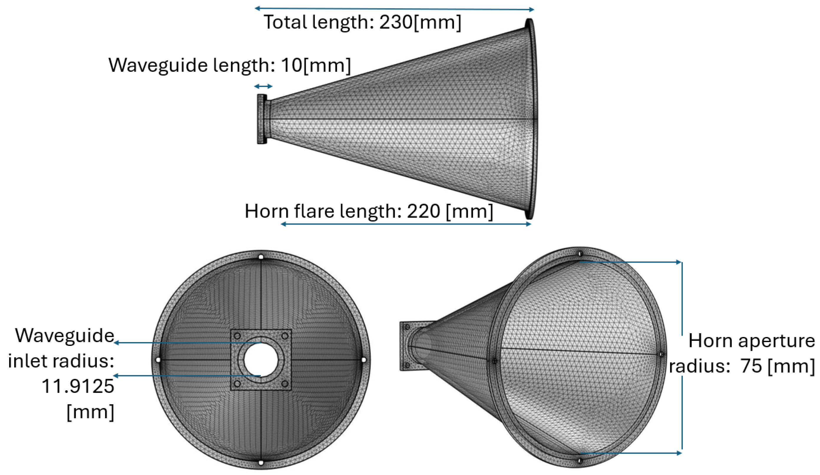
Figure 1. Geometry of the circular horn antenna showing the circular waveguide section, horn flare, and aperture dimensions.
Electronics 14 03191 g001
Figure 2. Geometry of the biconvex PTFE dielectric lens.
Electronics 14 03191 g002
Figure 3. Geometry of the circular horn antenna with integrated dielectric lens. Key dimensions and illustrative ray tracing demonstrate the focusing principle at the focal point (F). Note how divergent rays from the horn aperture are redirected by the lens to converge at the focal point.
Electronics 14 03191 g003
Figure 4. Simulated electric field r-component [V/m] in the x z -plane. (Left): with the dielectric lens. (Right): without the dielectric lens.
Electronics 14 03191 g004
Figure 5. Cross-validation of far-field radiation pattern simulations: comparison between COMSOL Multiphysics and CST Studio Suite results for the horn antenna without dielectric lens at 10 GHz. Excellent agreement validates our dual-simulation methodology.
Electronics 14 03191 g005
Figure 6. Simulated power density [W/m2] along the central propagation axis (z-axis) for the horn antenna with integrated dielectric lens at 10 GHz. The peak indicates the focal region.
Electronics 14 03191 g006
Figure 7. Simulated power density distribution [W/m2] in the x z -plane at the focal distance. Left: with the dielectric lens. Right: without the dielectric lens.
Electronics 14 03191 g007
Figure 8. The circular horn antenna structure during FDM 3D printing using a Qidi i Fast printer.
Electronics 14 03191 g008
Figure 9. The 3D-printed circular horn antenna structure (ABS) after surface metallization.
Electronics 14 03191 g009
Figure 10. Custom aluminum fixture designed to securely hold the partially milled PTFE lens during CNC machining of its second convex surface.
Electronics 14 03191 g010
Figure 11. Photograph of the fabricated biconvex PTFE dielectric lens after machining: (Left): view with scale reference, (Right): profile view.
Electronics 14 03191 g011
Figure 12. Photograph of the final assembled prototype: metallized 3D-printed horn antenna with integrated PTFE focusing lens.
Electronics 14 03191 g012
Figure 13. Illustrative experimental setup for measuring power density along the propagation axis (z-axis) of the lens horn antenna.
Electronics 14 03191 g013
Figure 14. Illustrative experimental setup for measuring the radiation pattern of the fabricated antenna.
Electronics 14 03191 g014
Figure 15. Measurement components for radiation pattern: Left: receiving horn antenna mounted on rotation stage connected to power meter sensor, Right: Keysight N1914A power meter analyzer display.
Electronics 14 03191 g015
Figure 16. Radiation pattern comparison: simulation vs. measurement for the horn antenna without the lens at 10 GHz.
Electronics 14 03191 g016
Figure 17. Axial power density comparison: simulation vs. experimental results for the horn antenna with integrated dielectric lens at 10 GHz.
Electronics 14 03191 g017
Figure 18. S11 performance comparison between simulation and measurement results: (a) complete antenna–lens system, and (b) horn antenna without dielectric lens. Both configurations demonstrate S11 values better than 10 dB across the frequency range, with good agreement between simulation and experimental results.
Electronics 14 03191 g018
Disclaimer/Publisher’s Note: The statements, opinions and data contained in all publications are solely those of the individual author(s) and contributor(s) and not of MDPI and/or the editor(s). MDPI and/or the editor(s) disclaim responsibility for any injury to people or property resulting from any ideas, methods, instructions or products referred to in the content.