Abstract
Fluid Antenna Systems (FASs) have recently emerged as a promising solution to address the demanding performance indicators (KPIs) and scalability challenges of future 6G mobile communications. By enabling agile control over both radiating position and antenna shape, FAS can significantly improve diversity gain and reduce outage probability through dynamic selection of the optimal radiation point, also known as port. Numerous theoretical studies have explored novel FAS concepts, often in conjunction with other wireless communication technologies such as multiple-input multiple-output (MIMO), Non-Orthogonal Multiple Access (NOMA), Reconfigurable Intelligent Surfaces (RIS), Integrated Sensing and Communication (ISAC), backscatter communication, and Semantic communication. To validate these theoretical concepts, several early-stage FAS hardware prototypes have been developed, including liquid–metal fluid antennas, mechanically movable antennas, pixel-reconfigurable antennas, and meta-fluid antennas. Initial measurements have demonstrated the potential advantages of FAS. This article provides a brief review of these early FAS hardware technologies. Furthermore, we share our vision for future hardware development and the corresponding challenges, aiming to fully release the potential of FAS and stimulate further research and development within the antenna research community.
1. Introduction
Mobile communications have dramatically evolved, progressing from basic voice transmission (1G) to sophisticated digital multimedia, culminating in the Internet of Everything (IoE) (5G). The International Telecommunication Union (ITU) forecasts mobile data traffic to reach 5 zettabytes (ZB) monthly by 2030 [1]. This progress faces challenges. Wireless channels are dynamic and unpredictable, causing signal strength fluctuations (fading) due to obstacles and reflections, leading to intermittent connections. Interference occurs when multiple devices use the same frequency, causing signal overlap and performance degradation. These channel variations and interference create significant challenges, demanding innovative solutions for reliable performance. Although 6G development is nascent, its proposed extreme connectivity—Tbps data rates, Kbps/Hz spectral efficiency, and µs latency—exceeds 5G demands.
Traditional mobile networks use adaptive techniques like dynamic frequency allocation and smart scheduling. However, we may have reached the limits of conventional antenna technology, with multiple-input multiple-output (MIMO) antennas representing the last major advancement. MIMO uses multiple spatially separated, fixed antennas to mitigate fading, but its use in mobile devices is limited by space. The fixed antenna positions require many antennas for high-speed, reliable connectivity. Base stations in 5G may have 64 or more antennas, while smartphones typically have fewer than four. This spatial constraint arises because antennas must be separated by at least half a wavelength for sufficient signal diversity.
Crucially, MIMO transmits and receives multiple data streams simultaneously over the same frequency using beamforming and spatial multiplexing. This requires channel state information (CSI), detailing signal propagation for each antenna pair. Extremely large-scale MIMO (XL-MIMO), proposed for 6G, anticipates hundreds of antennas, creating complexities in signal processing and CSI estimation, increasing cost due to numerous radio frequency (RF) chains, and raising power consumption, posing a severe scalability problem.
This leads to Fluid Antenna Systems (FASs), a concept recently proposed by Wong and Tong [2,3,4,5]. FAS envisions a “formless” antenna with a radiating position or/and shape that changes like fluid so the signal can navigate obstacles for reliable connections. Dynamically manipulating radiating positions across numerous closely spaced ports effectively mimics the diversity of countless fixed MIMO antennas [6]. Theoretical results presented in [7] show that a MIMO system in a 0.5λ by 0.5λ space achieves a maximum diversity gain of 16 while combining MIMO with FAS in the same space increases it to 81.
Unlike MIMO, where spatial diversity depends on the number of RF chains at the base stations, FAS introduces a new degree of freedom through position reconfigurability, even with a fixed number of RF chains. In multiuser communications on the same channel, FAS leverages the classical fading phenomenon—where signal strength varies spatially due to multipath propagation—to mitigate interference at the receiver by dynamically adjusting the antenna position. This represents a fundamental shift in interference management. Traditional methods rely on complex signal processing (precoding) at the base station, requiring channel state information (CSI) for all users. The FAS approach, known as Fluid Antenna Multiple Access (FAMA), mitigates the need for CSI estimation, feedback, and complex precoding optimization, addressing interference as it arrives at the receiver. This offers significant potential for improving the scalability of multiuser wireless communications.
Moreover, FAS offers a promising approach to enhancing several cutting-edge wireless technologies. In Simultaneous Wireless Information and Power Transfer (SWIPT), FAS can optimize both communication and power transfer efficiencies, a crucial benefit for mobile devices with limited RF chains [8,9]. For Integrated Sensing and Communications (ISAC), FAS enables dynamic adjustments of antenna properties, improving signal propagation and spatial diversity for both communication and sensing tasks [10,11]. In Non-Orthogonal Multiple Access (NOMA) systems, FAS can enhance user differentiation and mitigate interference, ensuring reliable decoding and preserving NOMA’s rate advantage [12]. FAS also has the potential to transform Reconfigurable Intelligent Surfaces (RIS) by acting as a “space surfer,” activating optimal receiving locations for constructive signal combination and simplifying complex phase shift optimizations [13,14,15,16]. Furthermore, FAS can bolster Physical Layer Security (PLS) by dynamically reconfiguring antenna elements, creating unique and unpredictable channel conditions that reduce the risk of information leakage [17,18,19]. Finally, in Mobile Edge Computing (MEC), FAS can ensure stable and high-quality connections between mobile devices and edge servers, facilitating efficient task offloading and resource distribution, which is essential for minimizing latency in 6G communications [20]. Essentially, FAS provides a versatile and adaptable antenna solution capable of significantly improving the performance of a variety of next-generation wireless communication systems.
When discussing FAS, it is crucial to clarify the nuanced differences between ‘traditional liquid antennas’ and ‘fluid antennas’. Traditional liquid antennas utilize liquids, often conductive ones like liquid metals or ionized water, or dielectric materials, such as pure water and oil, as their radiating or parasitic elements. The primary focus is on leveraging the material properties of the liquid to achieve desired reconfigurability. Historically, research explored how altering the shape or volume of a liquid conductor could modify the antenna’s operating frequency, polarization, and radiation pattern.
‘Fluid antennas’, however, represent a broader and more encompassing system-level approach to antenna design, emphasizing dynamic reconfigurability of the position of the radiating elements. While they may incorporate liquids, fluid antennas are not limited to them. The ‘fluid’ aspect refers to the ability to dynamically change the antenna’s configuration. This can be achieved through the traversal of antenna elements (whether liquid or solid), shape changes using fluidic materials, or reconfiguration via RF-switchable pixels.
The key distinction is that fluid antennas prioritize adaptability to the wireless environment. This involves dynamically optimizing the antenna’s properties to enhance signal reception or transmission. In essence, a fluid antenna system is any system where the antenna’s configuration can be altered. This can be accomplished by traversing a traditional liquid antenna or through numerous other methods, which will be further explained in this paper.
Fluid antennas represent a relatively new antenna concept, originating from techniques designed to mitigate fading and interference in multiuser environments of modern mobile communications. Currently, fluid antennas are not intended for use in all wireless communications, which means that traditional antenna assessment methods may not always be applicable. For instance, a Fluid Antenna System (FAS) does not require an extremely wide bandwidth like those ultra-wideband designs; it only needs to cover the operating bandwidth, which all reported antennas so far successfully do. Different from direction-finding applications such as radar, mobile phone antennas do not necessarily need high gain. If the received signal strength exceeds the noise level, it can be demodulated. Although a higher signal-to-noise ratio (SNR/SNIR) can support a higher data rate, it is not essential.
Although FAS is still in its early stages of development, it has a robust theoretical foundation, with over 150 peer-reviewed journal articles published in 2024 alone. While theoretical studies have shown the promise of FAS, comprehensive experimental validation and a functional FAS prototype have been missing.
While some early attempts at position-flexible antenna systems which are specifically designed for FAS application exist, they fall short of demonstrating the full potential described in the theoretical FAS literature. These attempts can be categorized into four approaches: liquid-metal fluid antennas, mechanically movable antennas, pixel-reconfigurable antennas, and meta-fluid antennas. This paper will briefly discuss these early approaches, outlining their advantages and disadvantages. Finally, we will share some perspectives and explain the technological challenges in developing hardware that can advance the application of FAS in the future.
In the subsequent sections, we will initially present various early attempts at FAS hardware implementations. We will briefly explain their operational mechanisms and demonstrated performance and identify essential areas requiring improvement for their effective utilization in future mobile communications. Subsequently, in the Discussion, we will propose some challenging research topics aimed at realizing the full potential of FAS, drawing upon our experience in this field. Finally, a concise conclusion will be provided.
2. Early Attempts of FAS Implementation
FAS empowers antenna engineers with design freedom by leaving hardware specifications open. Its core concept involves creating antennas capable of dynamically adjusting the radiator’s position, shape, orientation, or spatial dimensions. This versatility enables a diverse range of reconfigurable antenna designs. The primary focus of these early efforts has been to demonstrate the capabilities of radiating position agile and radiating shape-changing technologies. Integration with RF circuits, interoperability with existing devices, cost, and scalability are not top priorities at this stage and were not discussed in this paper.
Currently, four primary approaches exist: liquid-based fluid antennas, mechanically movable antennas, pixel reconfigurable antennas, and meta-fluid antennas. The following discussion explores these state-of-the-art designs in chronological order based on their reported appearance in the literature. We will outline the respective advantages and disadvantages of each approach for FAS hardware development.
2.1. Liquid-Metal Fluid Antennas (LM-FAS)
The use of liquid in antenna design has opened up exciting possibilities for achieving dynamic reconfigurability. Researchers have explored various approaches to manipulate antenna characteristics like frequency, polarization, and radiation patterns using these unique materials [21,22,23,24].
Among different materials in a liquid state, liquid metal is usually preferred because of its high conductivity [25]. One primary method involves altering the physical dimensions of the antenna by controlling the shape or volume of the liquid metal. This directly affects the resonant frequency. Research has demonstrated the use of microfluidic channels to manipulate liquid flow, enabling precise frequency tuning. Studies have shown liquid metal being used in patch antennas, where changing the patch size through liquid metal movement alters the resonant frequency [26].
Liquid metals can also be used as reactive loading elements, where their placement and shape within the antenna structure affect the impedance and resonant frequency. Researchers have integrated liquid metal into slot antennas and other structures to achieve frequency tuning [27,28]. Ref. [29] explores gravity-triggered liquid metal patch antennas to rotate or deform liquid metal structures to switch between different polarization states
Liquid metal can be used to create arrays of radiating elements, where the activation and arrangement of these elements can be dynamically controlled to shape the radiation pattern [30,31].
The development of reliable microfluidic systems is crucial for controlling liquid metal movement. Material compatibility and long-term stability are essential for practical applications, while actuation mechanisms, such as electrowetting and pressure-driven systems, also play a vital role in enabling dynamic reconfiguration. In addition, the fabrication techniques for the leakage-free container are also important. For example, 3D printing technology was used to create the containers [32,33,34]. Nevertheless, the ongoing research in this field is pushing the boundaries of antenna technology, paving the way for highly adaptable and versatile wireless communication systems.
However, it was not until 2020 that the concept of a position-agile LM-FAS prototype was reported [3]. It offers a unique approach to FAS by utilizing the flexibility of liquid metals like gallium alloys to mobilize the radiating position. The measurement setup of a pump-driven LM-FAS is shown in Figure 1. The latest LM-FAS described in [35] comprises a PCB substrate with a conductive ground plane on the bottom, a surface wave launcher connected to a K-type RF connector, a 3D-printed fluid container with embedded fluid channels, and a liquid-metal radiator within the channel. The surface wave launcher pattern is laser-engraved onto one end of a Rogers 5880 microwave dielectric substrate (εr = 2.2, thickness = 0.787 mm, and tan δ = 0.0009 at 10 GHz). The fluid container, fabricated using resin-based projection micro-stereolithography (epoxy resin, εr = 4.0, x-y-z printing resolution = 0.01 mm), contains the fluid channels that guide the liquid-metal radiator’s movement. While metallic or dielectric materials are viable radiator options, Galinstan liquid metal (electrical conductivity = 3.46 × 10⁶ S/m, thermal conductivity = 16.5 W/(K·m), material density = 6440 kg/m3, thermal diffusivity = 8.65578 × 10⁻⁶ m2/s) is chosen for its superior scattering capability. A 3V peristaltic micro-pump (11.9 mm ø × 13.9 mm ø × 32.9 mm3) [34], connected via thin silicon tubes, controls the liquid-metal radiator’s movement by pumping air in or out through the container’s inlets/outlets. For precise control, the inlets/outlets can be connected to a fluid control system designed for lab-on-a-chip devices [35]. Pump-free electrowetting techniques, capable of continuously traversing the fluid radiator at speeds up to 10 mm/s, could also be employed [36]. If the precise control system is available, the radiators in LM-FAS can basically be traversed continuously inside the fluid channels, giving a huge number of radiating positions.
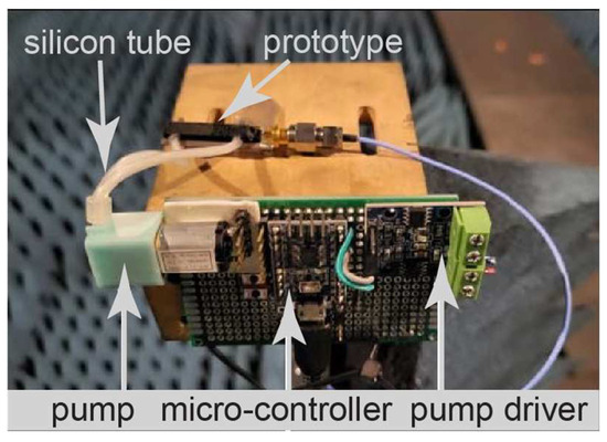
Figure 1.
Measurement setup of LM-FAS in an antenna chamber.
Figure 2 shows the operating principle of a single-channel LM-FAS. When the liquid radiator is in position a, it suffers from the interference caused by user 2. In this case, the liquid radiator will traverse to position b, which is a null in the direction of user 2, to alleviate the problem. Similarly, when the LM-FAS experiences a weak signal-to-noise ratio (SNR) for successful demodulation, the radiator position of LM-FAS can traverse to the one with a higher SNR. It is worth mentioning that, unlike the applications in radar, a high enough SNR for demodulation at the desirable data rate is already acceptable in mobile communication, a sharp and high gain radiation beam is not always necessary. The experimental results provided in [35] demonstrate that LM-FAS significantly improves outage probability and multiplexing gain for mmWave communications. However, several challenges remain. These include reducing temperature sensitivity, achieving precise position control, optimizing the fluid channel configuration, and meeting the faster response times required by future connectivity demands. Furthermore, as shown in Figure 3, a thin layer of gallium oxide forms upon air exposure, reducing its mobility, and residues adhered to the surface occur. Dilute acidic electrolytes, such as HCl, can mitigate this problem and maintain the liquid’s mobility.
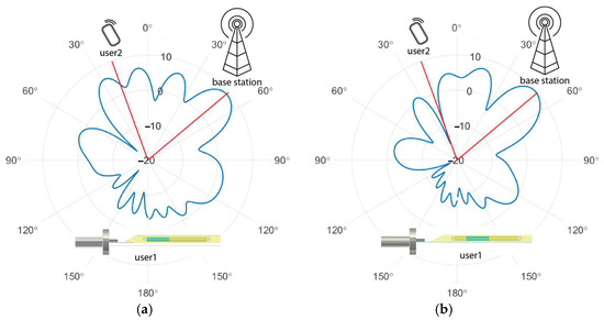
Figure 2.
Radiation patterns of single-channel liquid-metal-based FAS at different radiation positions [36] when the liquid metal radiator is located at (a) 0 mm and (b) 3 mm from the beginning of the liquid channel.
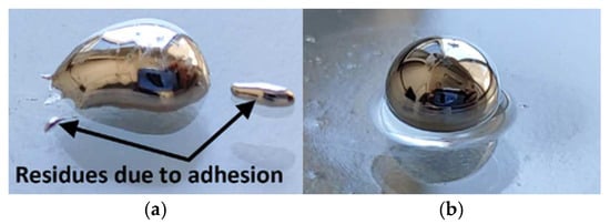
Figure 3.
(a) Residues of oxidized Galinstan, (b) Galinstan in diluted hydrochloric acid.
2.2. Mechanically Movable Antennas (MMA-FAS)
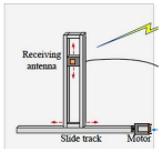
The first prototype of MMA-FAS was demonstrated in 2024 [37]; it is the most obvious way to realize the FAS concept involves using mechanically movable antennas [37,38]. This prototype separates communication functionality from the antenna positioner. The receiver module houses a conventional rigid four-element antenna array connected to RF chains, while the antenna-positioning module uses stepper motors and servo motors mounted on a mechanical slide to change antenna positions and orientation within a Cartesian coordinate system.
A host computer coordinates signal processing, antenna positioning, and motor movements. While this mechanically movable approach demonstrates the advantages of position flexibility of FAS, it faces serious feasibility limitations. The size and weight of the mechanical framework can restrict antenna placement options, while the inherent speed constraint of moving parts impacts responsiveness. Additionally, reliance on mechanical components introduces potential wear and tear, compromising long-term reliability. Exploring alternative methods that address these limitations is crucial for developing truly flexible and adaptable antenna systems.
Extending beyond conventional thinking boundaries, such as ‘liquid’ or ‘movable’, the term ‘fluid antennas’ encompasses any antenna architecture exhibiting dynamically controllable boundary conditions, variable occupied space (or topological structure), adaptive feed schemes, and modifiable eigenmode parity [39]. Material composition is inconsequential in this generalized definition. The following two designs can be considered within this framework.
2.3. Pixel Reconfigurable Antennas (PRA-FAS)
To fully realize the potential of FAS, antenna position/shape must be reconfigured at millisecond speeds or faster. Liquid-based and mechanical reconfiguration methods are inherently limited in their achievable speed. Electronically reconfigurable antennas, which use switches to alter antenna position, geometry or radiation characteristics, offer a viable alternative.
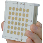
RF switches, such as PIN diodes, enable dynamic antenna shape modification by connecting or disconnecting supplementary metallic structures. A large number of switches theoretically allows for numerous configurations which exhibit useful radiation characteristics. For instance, the pixel reconfigurable antenna (PRA) approach has been explored for FAS [40]. System-level simulations and MIMO testbed experiments show strong agreement between the port correlation of PRA-FAS and traditional methods using mechanical movement or liquids.
A basic PRA-FAS has two layers. The E-slot patch antenna on the bottom layer is probe-fed through the ground plane, while the upper pixel substrate has metallic pixels printed on its top [40]. The E-slot patch serves as the radiation source for the pixel layer. Both the upper and lower layers are made of Rogers 4003C (εr = 3.55 and tan δ = 0.0027). There are 60 possible connections between adjacent pixels. Varying the conduction state of the inter-pixel connections allows for different antenna shapes. Ideally, to create the complete PRA-FAS, all pixel connections should be controlled by RF switches. This would allow for up to 260 configurations and, consequently, 260 pixel-composed patterns. However, in addition to the overly small size of individual pixels for effective radiation on their own, controlling a large number of RF switches requires a complex DC feeding network, which can negatively impact antenna efficiency. To simplify the design, based on the radiation performance and spatial correlation, only a limited number of RF switches are implemented [40]. The remaining inter-pixel connections are either hardwired or opened. After optimization, six switches between pixels are used, representing a good compromise between design flexibility and complexity. With six switches, this configuration can generate up to 26 = 64 pixel patterns. From these, 12 patterns that are well matched and satisfy the spatial correlation requirements are selected. The optimization of inter-pixel connections and spatial correlation of PRA-FAS is challenging due to the vast number of possible subsets and the non-linear nature of the objective function. These limitations, along with the inability to activate multiple states simultaneously, restrict the suitability of PRA-FAS. From this design, we can observe that fluid antennas, whose radiating position and shape are fast-changing and can provide a large number of states, represent a promising direction for future research.
2.4. Meta-Fluid Antennas (M-FAS)
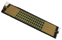
In addition to electronically changing the shape of FAS, the possibility of changing the radiating position of FAS was reported in [41]. The M-FAS consists of a 2D array of 120 elements arranged in 8 rows and 15 columns, as shown in Figure 4. Each element can be dynamically switched between radiating and non-radiating states using PIN diodes. A field-programmable gate array (FPGA) controller governs the elements, enabling selective activation of individual elements or multiple activations of elements to radiate or receive energy from the four parallel substrate-integrated waveguides (SIW) underneath into the air. This architecture integrates 120 individually addressable positions within a single RF chain, allowing the antenna to dynamically change its radiating position. Each element functions as a waveguide-fed magnetic dipole, extracting energy from the SIW and emitting electromagnetic waves into the free space. Given that the lattice size of the meta-element is much smaller than the wavelength, the elements can be considered as sampling points that capture the energy of the guided waves propagating within the SIW at their respective positions. Because the PIN diodes directly control the radiation from the elements, most of the computational resources can be allocated to optimizing the radiating position selection. The radiation performance of the elements is much more independent compared to a PRA-FAS; therefore, all 120 positions are available for optimization. Figure 4 shows the experiment with three transmitters (Tx) and one receiver (Rx) operating between 26 GHz and 27 GHz; it demonstrated that the M-FAS can achieve a high Signal-to-Interference-plus-Noise Ratio (SINR) exceeding 10.0 dB across the frequency band when the receiver switches its radiating position to the optimum at different time depending on the condition of the wireless channel as shown in Figure 5. This flow of radiating position with time realizes the FAS concept. The prototype effectively mitigates interference from the two undesirable transmitters, demonstrating the benefits of Fluid Antenna Multiple Access (FAMA). The M-FAS prototype’s high switching speed of 20 MHz, i.e., less than 0.1 μs per switch, facilitates SINR measurement during the experiment.
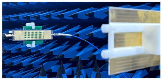
Figure 4.
Meta-fluid antenna system in the 3Tx-1Rx measurement setup.

Figure 5.
Illustration of the flow of the radiating position by switching on specific antenna elements with the best SNIR calculated by the algorithm at different times for best reception.
While the M-FAS uses PIN diodes for reconfiguration, it differs from conventional reconfigurable antennas. Traditional designs focus on optimizing radiation characteristics like operating frequency, polarization, and radiation pattern, but lack the ability to reposition the radiators themselves. This is because antenna experts typically evaluate antenna performance based on established metrics such as S11, radiation pattern, gain, and efficiency and seldom consider the advantages of position agility. However, wireless communication is about more than just antenna efficiency. The precise location of signal reception is more crucial. A fundamental characteristic of wireless communication is the random attenuation of received signals at any given point (due to Rayleigh fading in rich scattering environments), meaning communication performance fluctuates with antenna position. Therefore, the SINR (Signal-to-Interference-plus-Noise Ratio) is a more reliable parameter to consider, particularly in digital wireless communications.
Because the directivity of meta-element is low in the present form, it is desirable to retain the existing advantages of M-FAS while introducing a mechanism for achieving high gain in parallel. The feature is particularly important in millimeter-wave frequency bands. Furthermore, because the source signal is split among the 4 SIWs, the signal propagated in the SIWs without activated meta-elements is wasted. Therefore, a more energy-efficient feed network would further improve the performance of M-FAS.
3. Discussion: Research Opportunities
Recently, [27] explained the fundamental operational principles of fluid antennas from the antenna designers’ point of view by employing eigenmode theory and modal parity as analytical frameworks. A unified mathematical model is developed to elucidate the beam agility mechanism intrinsic to FAS, allowing for a direct comparison with reconfigurable intelligent surfaces (RISs) and time-modulated arrays (TMAs). Analysis reveals distinct radiation beamforming paradigms employed by FAS in contrast to RISs and TMAs.
As pointed out in [27], FAS can be characterized as antennas capable of repositioning their radiation patterns. Their multi-dimensional agility, encompassing eigenmode functions, modal parity, and feed positions, defines their fundamental intrinsic characteristics. Within this framework, smooth eigenmode reshaping is a fundamental property of all fluid antennas.
The authors believe this area warrants further study. A more comprehensive model would benefit not only the antenna community by providing design guidelines but also the wireless systems community for network planning. Such a model would provide the foundation for seamlessly integrating antenna design into wireless channel models, enabling holistic study and the identification of areas for improvement.
LM-FAS and MMA-FAS face limitations in response time, size, weight, and power consumption, raising concerns about their practicality. PRA-FAS offers fast state-switching, but its design complexity and limited spatial diversity pose scalability challenges. M-FAS faces concerns regarding gain and efficiency. These critical challenges must be overcome for FAS to achieve its full potential.
Key research areas include the following:
(i) Effective Element Feeding Network: Because of the dynamic nature of FAS’s radiating positions and/or shapes, traditional transmission line feeding methods may not be applicable. Therefore, a radiating-position-independent feeding method is required to avoid multiple, expensive RF chains. The recently reported programmable surface wave technique [30,31,32] allows the signal from a single RF chain to be guided to different positions on a surface and/or split into smaller signals. This technique shows potential for adaptation to FAS.
(ii) Multiple Radiating Position Activation: While single radiating position FAS have demonstrated impressive improvements, activating multiple radiating positions adds a new dimension. This could significantly improve efficient channel estimation and substantially increase the number of simultaneous connections from hundreds, if not thousands, of users and IoT devices within the same frequency band. This largely unexplored area presents a significant challenge: effectively managing and processing signals received from multiple, spatially separated elements.
(iii) On-demand Radiating Beam-Shaping: Existing FAS use predefined, primarily non-omnidirectional radiating beams. This creates blind spots as the radiator moves, limiting FAS’s ability to fully observe and leverage the full range of fading. Furthermore, after the channel environment is determined, a corresponding high-gain, narrow beam should be generated to optimize communication before the environment changes within milliseconds. This intelligent and adaptive radiation architecture, while promising, remains largely unexplored and has the potential to revolutionize future mobile communications.
(iv) Novel Low-Loss Materials for Transparent FAS: Novel low-loss materials supporting efficient electromagnetic wave radiation in the millimeter-wave (mmW) frequency band are crucial. New thin-film materials offering greater flexibility for reconfiguration are particularly critical for FAS success. These materials will not only ensure reliable performance but also reduce mmW power amplifier requirements. Transparent antennas are a current research focus. Transparent FAS can be seamlessly integrated into glass walls, transforming them into mobile base stations and onto handheld device screens, saving space and improving aesthetics.
4. Conclusions
This review paper introduces fluid antenna systems and their potential applications in future mobile communications in terms of hardware implementation. The objective of FAS is to avoid fading and minimize interference in multiuser scenarios. Distinguishing itself from other reviews of FAS, this paper explains the strengths and areas requiring improvement for various early approaches. Furthermore, to engage with researchers who are interested in this new area, we identify some potential research areas to facilitate the adoption of FAS in real-world applications. Finally, we provide Table 1 comparing the characteristics of the four Fluid Antenna System (FAS) early implementations: liquid–metal fluid antennas (LM-FAS), mechanically movable antennas (MMA-FAS), pixel reconfigurable antennas (PRA-FAS), and meta-fluid antennas (M-FAS) as a conclusion. Please note that some information is yet explicitly available in the literature, so those fields are marked as “Not specified” or “Not applicable”.

Table 1.
Comparison of the four early attempted FAS in the literature.
Author Contributions
Validation, K.-F.T. and B.L.; formal analysis, K.-F.T., B.L. and K.-K.W.; investigation, B.L.; data curation, K.-F.T.; writing—original draft preparation, K.-F.T.; funding acquisition, K.-F.T. and K.-K.W. All authors have read and agreed to the published version of the manuscript.
Funding
This research work of K. F. Tong was partly funded by Hong Kong Research Grants Council under the Area of Excellence Scheme under Grant AoE/E-101/23-N and the Hong Kong Metropolitan University, Staff Research Startup Fund: FRSF/2024/03, the work of Baiyang Liu was funded by Hong Kong Research Grants Council under the Area of Excellence Scheme under Grant AoE/E-101/23-N and the work of Kai-Kit Wong was supported by Engineering and Physical Sciences Research Council (EPSRC) under Grant EP/V052942/1.
Data Availability Statement
No new data were created or analyzed in this study. Data sharing is not applicable to this article.
Conflicts of Interest
The authors declare no conflicts of interest.
References
- Tariq, F.; Khandaker, M.R.A.; Wong, K.K.; Imran, M.A.; Bennis, M.; Debbah, M. A Speculative Study on 6G. IEEE Wirel. Commun. 2020, 27, 118–125. [Google Scholar] [CrossRef]
- Wong, K.; Tong, K.; Zhang, Y.; Zhongbin, Z. Fluid Antenna System for 6G: When Bruce Lee Inspires Wireless Communications. Electron. Lett. 2020, 56, 1288–1290. [Google Scholar] [CrossRef]
- Shen, Y.; Tong, K.F.; Wong, K.K. Beam-steering Surface Wave Fluid Antennas for MIMO Applications. Asia-Pac. Microw. Conf. Proc. APMC 2020, 2020, 634–636. [Google Scholar] [CrossRef]
- Wong, K.K.; Shojaeifard, A.; Tong, K.-F.; Zhang, Y. Performance Limits of Fluid Antenna Systems. IEEE Commun. Lett. 2020, 24, 2469–2472. [Google Scholar] [CrossRef]
- New, W.K.; Wong, K.-K.; Xu, H.; Wang, C.; Ghadi, F.R.; Zhang, J.; Rao, J.; Murch, R.; Ramírez-Espinosa, P.; Morales-Jimenez, D.; et al. A Tutorial on Fluid Antenna System for 6G Networks: Encompassing Communication Theory, Optimization Methods and Hardware Designs. IEEE Commun. Surv. Tutor. 2024. [Google Scholar] [CrossRef]
- Wong, K.K.; Tong, K.F.; Chen, Y.; Zhang, Y. Fast Fluid Antenna Multiple Access Enabling Massive Connectivity. IEEE Commun. Lett. 2023, 27, 711–715. [Google Scholar] [CrossRef]
- New, W.K.; Wong, K.K.; Xu, H.; Tong, K.F.; Chae, C.B. Fluid Antenna System: New Insights on Outage Probability and Diversity Gain. IEEE Trans. Wirel. Commun. 2023, 23, 128–140. [Google Scholar] [CrossRef]
- Zhou, L.; Yao, J.; Wu, T.; Jin, M.; Yuen, C.; Adachi, F. Fluid Antenna-Assisted Simultaneous Wireless Information and Power Transfer Systems. arXiv 2024, arXiv:2407.11307. [Google Scholar]
- Lin, X.; Yang, H.; Zhao, Y.; Hu, J.; Wong, K.-K. Performance Analysis of Integrated Data and Energy Transfer Assisted by Fluid Antenna Systems. arXiv 2023, arXiv:2311.07134. [Google Scholar]
- Zuo, Y.; Guo, J.; Chen, W.; Fan, W.; Sheng, B.; Xiao, F.; Jin, S. Fluid Antenna-enabled Integrated Sensing, Communication, and Computing Systems. arXiv 2024, arXiv:2409.11622. [Google Scholar]
- Zou, J.; Xu, H.; Wang, C.; Xu, L.; Sun, S.; Meng, K.; Masouros, C.; Wong, K.-K. Shifting the ISAC Trade-Off with Fluid Antenna Systems. IEEE Wirel. Commun. Lett. 2024, 13, 3479–3483. [Google Scholar] [CrossRef]
- New, W.K.; Wong, K.K.; Xu, H.; Tong, K.F.; Chae, C.B.; Zhang, Y. Fluid Antenna System Enhancing Orthogonal and Non-Orthogonal Multiple Access. IEEE Commun. Lett. 2024, 28, 218–222. [Google Scholar] [CrossRef]
- Lai, X.; Yao, J.; Zhi, K.; Wu, T.; Morales-Jimenez, D.; Wong, K.K. FAS-RIS: A Block-Correlation Model Analysis. IEEE Trans. Veh. Technol. 2024, 74, 3412–3417. [Google Scholar] [CrossRef]
- Zhu, J.; Luo, Q.; Chen, G.; Xiao, P.; Xiao, Y.; Wong, K.K. Fluid Antenna Empowered Index Modulation for RIS-aided mmWave Transmissions. IEEE Trans. Wirel. Commun. 2024, 24, 1635–1647. [Google Scholar] [CrossRef]
- Ghadi, F.R.; Wong, K.K.; New, W.K.; Xu, H.; Murch, R.; Zhang, Y. On Performance of RIS-Aided Fluid Antenna Systems. IEEE Wirel. Commun. Lett. 2024, 13, 2175–2179. [Google Scholar] [CrossRef]
- Wang, G.; Zhang, J.; Xu, K.; Ni, Y.; Wu, Y. Performance Analysis of Multi-RIS-Aided Fluid Antenna Systems Under Nakagami-m Fading Channels. In Proceedings of the 2024 16th International Conference on Wireless Communications and Signal Processing (WCSP), Hefei, China, 24–26 October 2024; pp. 360–365. [Google Scholar] [CrossRef]
- Chen, Y.; Xu, H.; Xu, T. Enhancing Communication Resilience through Fluid Antenna Index Modulation. In Proceedings of the 2024 IEEE/CIC International Conference on Communications in China, ICCC 2024, Hangzhou, China, 7–9 August 2024; pp. 1304–1309. [Google Scholar] [CrossRef]
- Vega-Sánchez, J.D.; Urquiza-Aguiar, L.F.; Mora, H.R.C.; Garzón, N.V.O.; Osorio, D.P.M. Fluid Antenna System: Secrecy Outage Probability Analysis. IEEE Trans. Veh. Technol. 2024, 73, 11458–11469. [Google Scholar] [CrossRef]
- Ghadi, F.R.; Wong, K.K.; Lopez-Martinez, F.J.; New, W.K.; Xu, H.; Chae, C.B. Physical Layer Security over Fluid Antenna Systems: Secrecy Performance Analysis. IEEE Trans. Wirel. Commun. 2024, 23, 18201–18213. [Google Scholar] [CrossRef]
- Zuo, Y.; Guo, J.; Sheng, B.; Dai, C.; Xiao, F.; Jin, S. Fluid Antenna for Mobile Edge Computing. IEEE Commun. Lett. 2024, 28, 1728–1732. [Google Scholar] [CrossRef]
- Huang, Y.; Xing, L.; Song, C.; Wang, S.; Elhouni, F. Liquid Antennas: Past, Present and Future. IEEE Open J. Antennas Propag. 2021, 2, 473–487. [Google Scholar] [CrossRef]
- Dey, A.; Guldiken, R.; Mumcu, G. Wideband frequency tunable liquid metal monopole antenna. In Proceedings of the 2013 IEEE Antennas and Propagation Society International Symposium (APSURSI), Orlando, FL, USA, 7–13 July 2013; pp. 392–393. [Google Scholar] [CrossRef]
- Paracha, K.N.; Butt, A.D.; Alghamdi, A.S.; Babale, S.A.; Soh, P.J. Liquid Metal Antennas: Materials, Fabrication and Applications. Sensors 2019, 20, 177. [Google Scholar] [CrossRef]
- Motovilova, E.; Huang, S.Y. A Review on Reconfigurable Liquid Dielectric Antennas. Materials 2020, 13, 1863. [Google Scholar] [CrossRef] [PubMed]
- Daeneke, T.; Khoshmanesh, K.; Mahmood, N.; de Castro, I.A.; Esrafilzadeh, D.; Barrow, S.J.; Dickey, M.D.; Kalantar-Zadeh, K. Liquid metals: Fundamentals and applications in chemistry. Chem. Soc. Rev. 2018, 47, 4073–4111. [Google Scholar] [CrossRef] [PubMed]
- Hayes, G.J.; So, J.H.; Qusba, A.; Dickey, M.D.; Lazzi, G. Flexible liquid metal alloy (EGaIn) microstrip patch antenna. IEEE Trans. Antennas Propag. 2012, 60, 2151–2156. [Google Scholar] [CrossRef]
- Saghati, A.P.; Batra, J.S.; Kameoka, J.; Entesari, K. Miniature and Reconfigurable CPW Folded Slot Antennas Employing Liquid-Metal Capacitive Loading. IEEE Trans. Antennas Propag. 2015, 63, 3798–3807. [Google Scholar] [CrossRef]
- Arbelaez, A.; Singh, A.; Saavedra, C. Frequency Tuning of Annular Slot Antenna using Liquid Metal Overlay Line. In Proceedings of the 2020 IEEE International Symposium on Antennas and Propagation and North American Radio Science Meeting, Montréal, QC, Canada, 5–10 July 2020; pp. 405–406. [Google Scholar] [CrossRef]
- Qin, P.; Huang, G.-L.; Liang, J.-J.; Wang, Q.-Y.; Fu, J.-H.; Zhu, X.-Y.; Liu, T.-Y.; Gui, L.; Liu, J.; Deng, Z.-S. A Gravity-Triggered Liquid Metal Patch Antenna with Reconfigurable Frequency. Micromachines 2021, 12, 701. [Google Scholar] [CrossRef]
- AMorishita, M.; Kitamura, C.K.Y.; Ohta, A.T.; Shiroma, W.A. A Liquid-Metal Monopole Array with Tunable Frequency, Gain, and Beam Steering. IEEE Antennas Wirel. Propag. Lett. 2013, 12, 1388–1391. [Google Scholar] [CrossRef]
- CKitamura, K.Y.; Morishita, A.M.; Chun, T.F.; Tonaki, W.G.; Ohta, A.T.; Shiroma, W.A. A liquid-metal reconfigurable Yagi-Uda monopole array. In Proceedings of the IEEE MTT-S International Microwave Symposium Digest, Seattle, WA, USA, 2–7 June 2013. [Google Scholar] [CrossRef]
- Borda-fortuny, C.; Tong, K.-F.; Wong, K.-K. A low-cost fluid switch to reconfigure the operating frequency band of a Vivaldi antenna. IEEE Antennas Wirel. Propag. Lett. 2017, 16, 3151–3154. [Google Scholar] [CrossRef]
- Borda-Fortuny, C.; Cai, L.; Tong, K.F.; Wong, K.-K. Low-Cost 3D-Printed Coupling-Fed Frequency Agile Fluidic Monopole Antenna System. IEEE Access 2019, 7, 95058–95064. [Google Scholar] [CrossRef]
- Li, H.; Fortuny, C.B.; Tong, K.-F.; Wong, K.-K. Coupling-fed frequency agile monopole fluid antenna. In Proceedings of the 2016 IEEE Conference on Antenna Measurements & Applications (CAMA), Syracuse, NY, USA, 23–27 October 2016; pp. 1–3. [Google Scholar] [CrossRef]
- Shen, Y.; Tang, B.; Gao, S.; Tong, K.-F.; Wong, H.; Wong, K.-K.; Zhang, Y. Design and Implementation of mmWave Surface Wave Enabled Fluid Antennas and Experimental Results for Fluid Antenna Multiple Access. arXiv 2024, arXiv:2405.09663. [Google Scholar]
- Shen, Y.; Tong, K.F.; Wong, K.K. Radiation Pattern Diversified Single-Fluid-Channel Surface-Wave Antenna for Mobile Communications. In Proceedings of the 2022 IEEEF—APS Topical Conference on Antennas and Propagation in Wireless Communications, APWC 2022, Cape Town, South Africa, 5–9 September 2022; pp. 49–51. [Google Scholar] [CrossRef]
- Dong, Z.; Zhou, Z.; Xiao, Z.; Zhang, C.; Li, X.; Min, H.; Zeng, Y.; Jin, S.; Zha, R. Movable Antenna for Wireless Communications: Prototyping and Experimental Results. arXiv 2024, arXiv:2408.08588. [Google Scholar]
- Zhu, L.; Ma, W.; Zhang, R. Movable Antennas for Wireless Communication: Opportunities and Challenges. IEEE Commun. Mag. 2024, 62, 114–120. [Google Scholar] [CrossRef]
- Lu, W.-J.; He, C.X.; Zhu, Y.; Tong, K.F.; Wong, K.K.; Shin, H.; Cui, T.J. Fluid Antennas: Reshaping Intrinsic Properties for Flexible Radiation Characteristics in Intelligent Wireless Networks. arXiv 2025, arXiv:2501.02911. [Google Scholar]
- Zhang, J.; Rao, J.; Li, Z.; Ming, Z.; Chiu, C.-Y.; Wong, K.-K.; Tong, K.-F.; Murch, R. A Novel Pixel-Based Reconfigurable Antenna Applied in Fluid Antenna Systems with High Switching Speed. IEEE Open J. Antennas Propag. 2024, 6, 212–228. [Google Scholar] [CrossRef]
- Liu, B.; Tong, K.-F.; Fellow, I.; Wong, K.-K.; Chae, C.-B.; Wong, H. Be Water, My Antennas: Riding on Radio Wave Fluctuation in Nature for Spatial Multiplexing using Programmable Meta-Fluid Antenna. arXiv 2025, arXiv:2502.04693. [Google Scholar]
Disclaimer/Publisher’s Note: The statements, opinions and data contained in all publications are solely those of the individual author(s) and contributor(s) and not of MDPI and/or the editor(s). MDPI and/or the editor(s) disclaim responsibility for any injury to people or property resulting from any ideas, methods, instructions or products referred to in the content. |
© 2025 by the authors. Licensee MDPI, Basel, Switzerland. This article is an open access article distributed under the terms and conditions of the Creative Commons Attribution (CC BY) license (https://creativecommons.org/licenses/by/4.0/).

