Article

Energy Management of Hybrid Electric Commercial Vehicles Based on Neural Network-Optimized Model Predictive Control

1
School of Automotive Studies, Tongji University, Shanghai 201804, China
2
Department of Engineering, University of Cambridge, Trumpington Street, Cambridge CB2 1PZ, UK
3
College of Urban Transportation and Logistics, Shenzhen Technology University, Shenzhen 518118, China
*
Author to whom correspondence should be addressed.
Electronics 2025, 14(16), 3176; https://doi.org/10.3390/electronics14163176 (registering DOI)
Submission received: 16 July 2025 / Revised: 5 August 2025 / Accepted: 7 August 2025 / Published: 9 August 2025

Abstract

Energy management for hybrid electric commercial vehicles, involving continuous power output and discrete gear shifting, constitutes a typical mixed-integer programming (MIP) problem, presenting significant challenges for real-time performance and computational efficiency. To address this, this paper proposes a physics-informed neural network-optimized model predictive control (PINN-MPC) strategy. On one hand, this strategy simultaneously optimizes continuous and discrete states within the MPC framework to achieve the integrated objectives of minimizing fuel consumption, tracking speed, and managing battery state-of-charge (SOC). On the other hand, to overcome the prohibitively long solving time of the MIP-MPC, a physics-informed neural network (PINN) optimizer is designed. This optimizer employs the soft-argmax function to handle discrete gear variables and embeds system dynamics constraints using an augmented Lagrangian approach. Validated via hardware-in-the-loop (HIL) testing under two distinct real-world driving cycles, the results demonstrate that, compared to the open-source solver BONMIN, PINN-MPC significantly reduces computation time—dramatically decreasing the average solving time from approximately 10 s to about 5 ms—without sacrificing the combined vehicle dynamic and economic performance.

1. Introduction

With the escalation of global energy crises and environmental issues, commercial vehicles, as the core carriers of logistics transportation, have attracted significant attention for their energy consumption and emission problems [1,2]. The electrification and intelligence of commercial vehicles provide an important technical path for energy conservation and emission reduction in the transportation sector [3]. Electrification technology significantly reduces the full-life-cycle carbon emission intensity and fuel consumption of commercial vehicles through multi-energy collaborative optimization of power batteries and engines [4,5,6,7]. The introduction of intelligent technology further enhances energy utilization efficiency. Global energy prediction based on vehicle networking (V2X), working condition adaptive control combined with big data analysis, and dynamic planning of energy flow for multi-objective collaborative optimization lay a technical foundation for fine-grained management of EMSs [8,9,10]. In particular, the application of 5G communication and edge computing technologies enables the fusion processing of real-time traffic information and vehicle status data, providing new solutions for dynamic optimization of energy distribution [11].
However, the multi-power-source coupling characteristics of hybrid commercial vehicles significantly increase the design complexity of EMSs [12]. At the energy distribution level, the power splitting of the engine-motor-battery system needs to balance instantaneous efficiency and long-term durability; gear optimization needs to consider discrete variables while coordinating transmission system efficiency and driving smoothness; and the exponential growth of in-vehicle information (including high-precision map data, real-time traffic signals, battery health status, etc.) imposes strict requirements on the computational efficiency of control algorithms [13]. The current mainstream EMS methods mainly include three categories: rule-based [14,15], optimization-based [16,17,18,19], and data-driven and intelligent control strategies [20,21].
Rule-based energy management strategies control the energy distribution of hybrid power systems through pre-defined heuristic rules. These rules typically rely on expert knowledge or engineering experience, offering advantages of simple design and easy real-time implementation. However, due to the lack of consideration for future driving conditions, these strategies have limitations in adapting to different driving cycles and struggle to achieve globally optimal control effects [22,23].
Among optimization-based methods, global optimization (such as dynamic programming (DP), Pontryagin’s minimum principle (PMP), etc.) [24] and real-time optimization (such as model predictive control, MPC) [25,26] have received extensive attention from researchers. Global optimization algorithms require global static road or dynamic traffic information, which is almost impossible to fully obtain throughout the driving process, so they are usually only used as a benchmark for evaluating other algorithms in simulations. For example, Anselma’s slope-weighted dynamic programming algorithm improves computational efficiency by 30% while maintaining fuel economy, but it remains limited to offline scenarios [27]. In contrast, MPC only requires information over a future time or distance and can explicitly consider multi-objective optimization and constraints, making it an effective solution for energy-saving problems. It has been widely applied in energy-saving control, energy optimization, and vehicle planning for trucks and other connected vehicles [28,29]. Hong et al. [30] considered the difference between actual driver operations and optimal energy-saving driving, developing a predictive cruise driving assistance system that optimizes energy-saving driving for electric vehicles while considering driver intent. This system achieves a driving process that balances driving comfort and energy efficiency, and after testing in random traffic environments, it ultimately achieves an energy-saving effect of over 3%. A novel real-time iteration sequential convex programming (RTI-SCP) algorithm has been proposed to solve nonlinear model predictive control with convex–concave constraints. It enhances computational efficiency and overall control performance for real-time implementation, while formulating the eco-driving strategy for autonomous vehicles as a convex–concave programming problem for the first time [31].
In recent years, the rise of data-driven and intelligent algorithms has injected new momentum into EMSs. Deep reinforcement learning (DRL) learns optimal strategies through interactions between agents and the environment, combining model-free properties and adaptability. Li et al. [32] used a deep reinforcement learning method to extract interaction information between vehicles through an attention mechanism and integrate it into energy management strategy optimization. The results show that the difference in energy-saving rate between this method and dynamic programming is reduced from 8.7% to 5.6%. Meanwhile, significant progress has been made in energy-saving optimization control for vehicle platoons using such methods. For example, Zhang et al. [33] used a multi-agent reinforcement learning-based energy management framework to achieve energy-saving optimization control for hybrid vehicle platoons, which achieved a 19.2% energy-saving effect compared with rule-based methods. Although reinforcement learning methods are currently one of the mainstream research directions, their short-term on-vehicle application remains unfeasible due to high data demand and challenges in generalization performance.
Model predictive control (MPC) is highly valued in energy-saving control research for its strengths in handling multi-objective optimization, explicit constraints, and utilization of future finite-horizon information, making it well-suited for vehicle energy management. Although MPC has been widely applied in scientific research on energy-saving control, its large-scale application in actual vehicles remains limited. A major reason is that MPC itself has a heavy computational burden, while in-vehicle control units (VCUs) have weak computational capabilities due to cost constraints. Therefore, how to improve real-time performance while ensuring solution accuracy has become an urgent problem to solve, and many researchers have dedicated themselves to this. Notably, a neural network optimizer with soft-argmax operator was applied to MIMPC for eco-gearshift in 2-speed EVs, achieving comparable energy savings to BONMIN with faster solution speed [34]. Wengtong Shi et al. [35] proposed a neural network optimizer based on the idea of a physics-informed neural network (PINN) to accelerate the solution of MPC problems. This method fully utilizes data and physical constraints, embedding physical laws into the neural network training process to reduce dependence on large-scale labeled data and ensure that network outputs conform to system dynamics. Compared with traditional numerical solution methods, this neural network optimizer only needs to perform a small number of matrix multiplications and additions, greatly reducing the computational burden, achieving a solution time of approximately 0.07 ms per step, which is more than 70% faster than the mainstream nonlinear MPC solver Acados, while not sacrificing control performance. This accelerated solution method combining physical prior and data-driven advantages provides a new technical path for the application of real-time nonlinear MPC in autonomous driving and other high-dynamic systems.
However, although the PINN-based method in this literature has achieved remarkable results in accelerating the solution of MPC problems, this method mainly targets the optimization of continuous variables. In the optimization problem of hybrid heavy commercial vehicles studied in this paper, the variables involved include both continuous and discrete quantities, making it a hybrid system belonging to mixed-integer optimization problems. Due to the coupling relationship between discrete and continuous variables, which need to be optimized simultaneously, this problem faces higher complexity and challenges in solving.
To improve the solution speed of mixed-integer based MPC and ensure its real-time performance in actual commercial vehicles, this paper proposes a PINN considering discrete variables to address the problem of long solution times caused by mixed-integer MPC applications. Overall, the original contributions of this paper are as follows:
  • The minimum fuel energy management strategy for hybrid electric vehicles under a given driving cycle is investigated, with consideration of the influence of transmission gear information, and mixed-integer programming is introduced into problem solving.
  • The energy management strategy is optimized using a model predictive control algorithm, and a PINN is designed to address the issue of long solution time arising from the application of MPC.
  • Hardware-in-the-loop (HIL) simulation tests are conducted. The experimental results demonstrate that under the experimental conditions, the energy consumption optimization effect achieved is nearly consistent with that of the BONMIN mixed-integer solver (with errors of only 0.9% and 0.25%), while the solution time is reduced from an average of 10 s to approximately 5 milliseconds.
The structure of this paper is organized as follows: Section 2 introduces the modeling ideas of each power component model and the vehicle model of the target vehicle, and verifies the simulation model using the target vehicle test data. Section 3 describes in detail the controller design of the model predictive control-based energy management strategy for the P2-type single-shaft parallel hybrid system, and introduces the design of the neural network optimizer and the generation of relevant datasets. Section 4 details the construction details and training ideas of the neural network and presents the online simulation results.

2. Vehicle Modeling

This study focuses on a P2 parallel hybrid heavy-duty commercial vehicle, as illustrated in Figure 1. The engine and motor can operate independently or jointly, with a clutch enabling power coupling or decoupling. The motor functions as both a propulsion source and a regenerative braking unit.

2.1. Vehicle Dynamics

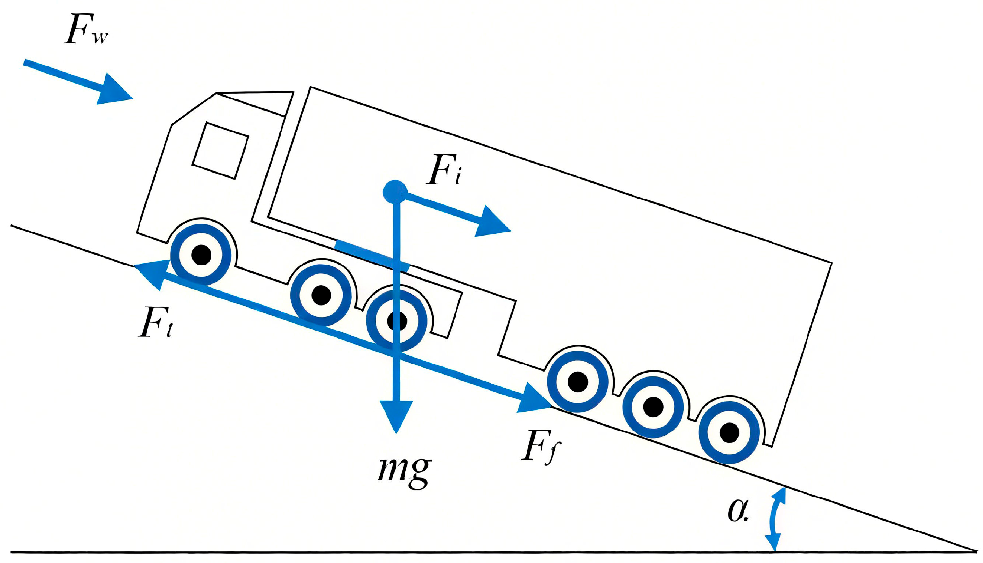
The longitudinal dynamics model is governed by the vehicle resistance equation. The driving force, supplied by the engine and motor, counteracts rolling resistance F f , aerodynamic drag F w , gradient resistance F i , and acceleration resistance F j . The dynamic equilibrium is expressed as
F t = F f + F i + F w + F j ,
( T e + T m ) i g i 0 η t r = m g f cos α + 1 2 C d A ρ v veh 2 + m g sin α + δ m v ˙ veh ,
where F t is the total driving force from engine torque T e and motor torque T m . Key parameters include rolling resistance coefficient f , vehicle mass m , gravitational acceleration g , road gradient α , air density ρ frontal area A , drag coefficient C d , longitudinal speed v , transmission gear ratio i g , final drive ratio i 0 , mechanical efficiency η t , wheel radius r , and equivalent rotational inertia δ . The longitudinal dynamics model is shown in Figure 2.

2.2. Engine Model

The engine fuel consumption model is developed based on experimental data. Using the engine speed n e and torque T e , the universal characteristic map ( f m a p ) is employed to obtain the fuel consumption rate b e . The engine fuel consumption m ˙ f is then determined by the engine power equation and the fuel consumption calculation formula. The universal characteristics of the engine are shown in Figure 3. The dynamic process is expressed as
b e = f map ( T e , n e ) ,
P e = T e n e 9550 ,
m · f = P e · b e 3600

2.3. Motor Model

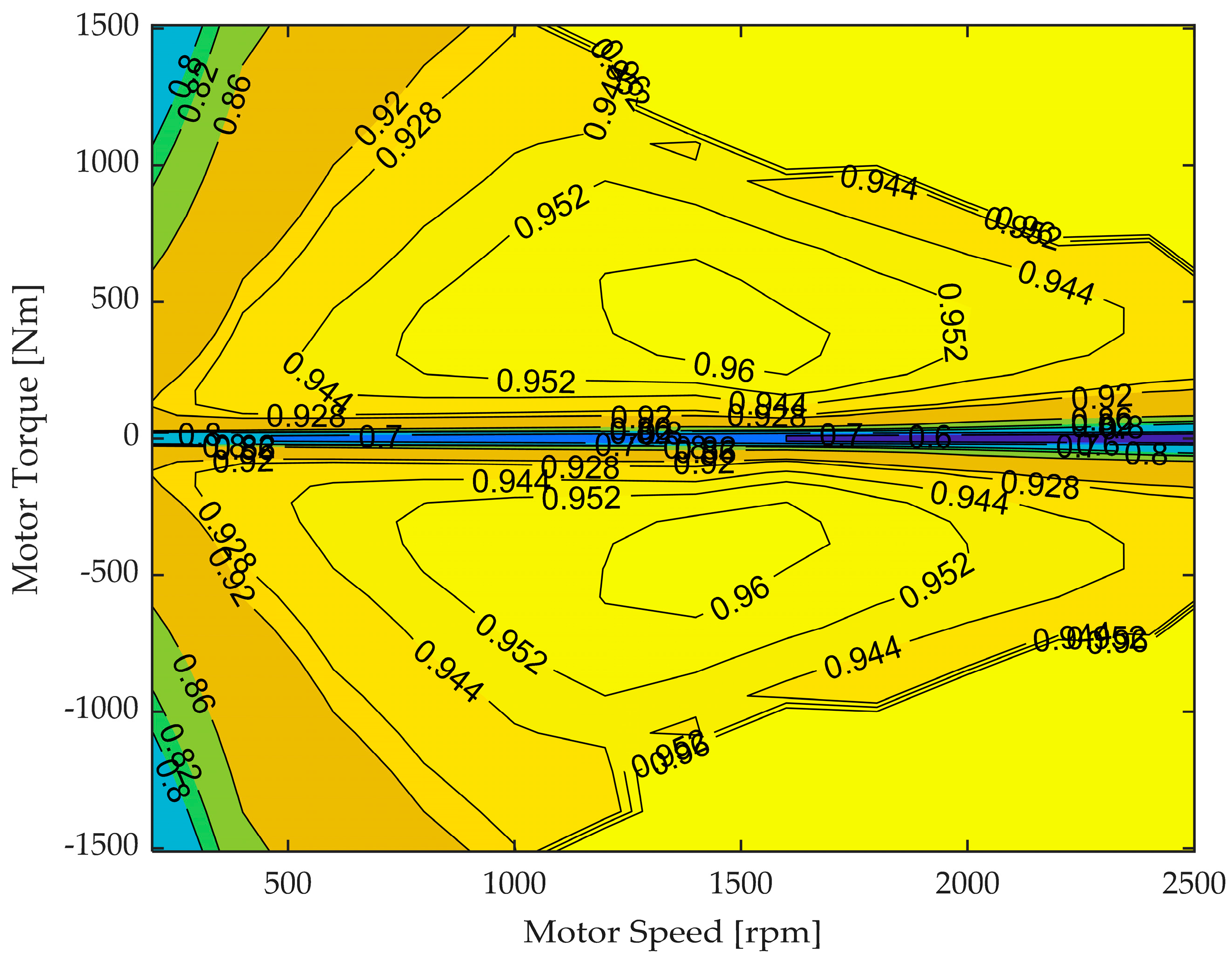
Similarly, the motor model is constructed using experimental data. Based on the motor speed n m and torque T m , the motor’s efficiency η m is obtained by using the universal characteristic map ( g m a p ) for the motor. The motor power P m is computed by the power calculation formula, from which the energy consumption of the motor can be derived. The universal characteristics of the motor are shown in Figure 4. The dynamic process is given by the following expression:
η m = g map ( T m , n m ) ,
P m = T m n m 9550 η m , i f   T m 0 T m n m η m 9550 , o t h e r w i s e ,

2.4. Battery Model

An equivalent internal resistance model is utilized to develop the battery model. In this model, the effect of the battery’s state-of-charge (SOC) on the battery voltage V o c and resistance R int is taken into account. Consequently, the battery current I and the rate of SOC change can be calculated via the motor power computation as
I ( t ) = V oc V oc 2 4 R int P m ( t ) 2 R int ,
S O ˙ C ( t ) = I ( t ) / Q ,
where Q denotes the total charge of the battery.

3. Learning-Based Energy Management Strategy

3.1. Problem Description

To achieve efficient energy management control for the P2-structured hybrid system, this paper formulates an optimization problem based on model predictive control (MPC) that accounts for both the mixed dynamic characteristics and the energy-optimal objectives. The optimization problem seeks the optimal control sequence over a finite prediction horizon while fully considering the evolution characteristics of both continuous and discrete system states and various practical constraints. Specifically, the energy management strategy aims to find the optimal gear selection and torque distribution within a given driving cycle to minimize the objective function. The purpose of the optimization problem is to track a specified reference speed with minimal energy consumption while ensuring that the battery SOC remains close to the given reference value and that both the control inputs and states satisfy the system’s constraints during the cycle.
The following subsections provide a systematic explanation of the system state and control variable modeling, dynamics modeling, cost function formulation, and constraint setting.

3.1.1. System State Equations

The optimal control problem is subject to the following state transition equation:
x ˙ = f ( x ( t ) , u ( t ) ) = ( v ˙ ( t ) , S O ˙ C ( t ) ) T ,
Based on the vehicle model developed in Section 2, the following relationship is derived:
v ˙ ( t ) = ( T e + T m ) i g i 0 η T r ( m g f cos α + m g sin α + C D A u 2 21.15 ) ,
S O ˙ C ( t ) = V o c V O C 2 4 R int P b a t ( t ) 2 R int Q .

3.1.2. Objective Function

The objective function is formulated as the sum of the engine fuel consumption, speed tracking error penalty, and battery SOC deviation penalty:
J = ω 1 t 0 t f m ˙ f ( t ) d t + ω 2 J ( x v ) + ω 3 J ( x S O C ) ,
where ω 1 , ω 2 , ω 3 represent the weighting coefficients for the fuel consumption rate, the speed tracking error penalty, and the battery SOC deviation penalty, respectively. The specific expressions are
J ( x v ) = t 0 t f ( v ( t ) v r e f ( t ) ) 2 d t ,
J ( x S O C ) = t 0 t f ( S O C ( t ) S O C r e f ) 2 d t ,
where v r e f ( t ) denotes the reference vehicle speed over the cycle, and S O C r e f is the reference battery SOC (set as a constant 0.4 in this study, thereby maintaining the battery SOC around 0.4).
In order to assess the total energy consumption during simulation and testing, an equivalent fuel consumption metric is introduced, which integrates both the engine fuel usage and the net energy change of the battery. This is particularly important when the battery SOC exhibits drift during a driving cycle, ensuring a fair comparison between different strategies.
Specifically, the energy change of the battery Δ E = Δ S O C × Q b a t is calculated based on the difference between the terminal and initial SOC values Δ S O C multiplied by the battery’s rated capacity Q b a t (in kWh). This energy is then converted into an equivalent fuel mass M b a t using a conversion factor of 5.36 kWh/L:
M b a t = Δ S O C × Q b a t 5.36 ,
When the SOC decreases (battery discharging), M b a t is positive, representing energy released by the battery; when the SOC increases (charging), M b a t becomes negative, reflecting fuel-equivalent savings from regenerative braking or energy recovery. The final equivalent fuel consumption M e q u is the sum of the engine’s actual fuel consumption M f and the battery’s equivalent fuel mass:
M e q u = M f + M b a t = M f + Δ S O C × Q b a t 5.36 ,
This formula will be used throughout subsequent simulation and hardware-in-the-loop (HIL) testing stages to ensure consistency in the energy consumption evaluation, regardless of SOC drift during operation.

3.1.3. Variables and Constraints

The system state variables x ( t ) = [ v ( t ) , S O C ( t ) ] T include v ( t ) , representing vehicle speed, and S O C ( t ) , representing the battery state-of-charge. The control variables u ( t ) = [ T e ( t ) , T m ( t ) , i g ( t ) ] T include the engine torque, motor torque, and gearbox gear selection. All state and control variables must satisfy predefined constant constraints:
S O C min v min n e , min n m , min T e , min T m , min i g , min S O C ( t ) v ( t ) n e ( t ) n m ( t ) T e ( t ) T m ( t ) i g ( t ) S O C max v max n e , max n m , max T e , max T m , max i g , max ,
where n e , n m denote the engine and motor speeds, respectively.
The gearbox gear command is an integer control variable defined as
i g ( t ) { 1 , 2 , 3 , , 12 } ,

3.2. MPC-Based Controller

For the continuous system, Euler’s method is applied to discretize the system, yielding the following discrete form:
x ( k + 1 ) = f m ( x ( k ) , u ( k ) ) Δ t + x ( k ) ,
where f m denotes the system’s gradient at time k, and Δ t is the sampling time.
Considering that the objective function of the energy management strategy incorporates engine fuel consumption, the system output is defined as the engine fuel consumption rate m ˙ f ( k ) based on the prediction model. This leads to the following specific expression:
y ( k ) = m ˙ f ( k ) = h ( x ( k ) , u ( k ) ) .
Let N c denote the control horizon and N p denote the prediction horizon, with N p N c 1 . At the sampling time k, the system control sequence, and output sequence are represented as
U ( k ) = u ( k ) | k u ( k + 1 ) | k u ( k + N c 1 ) | k , Y ( k ) = y ( k ) | k y ( k + 1 ) | k y ( k + N p 1 ) | k .
At sampling time k, the predicted state of the system is given by
x ( k + 1 | k ) = f m ( x ( k | k ) , u ( k | k ) ) Δ t + x ( k | k ) x ( k + 2 | k ) = f m ( x ( k + 1 | k ) , u ( k + 1 | k ) ) Δ t + x ( k + 1 | k ) x ( k + N c | k ) = f m ( x ( k + N c 1 | k ) , u ( k + N c 1 | k ) ) Δ t + x ( k + N c 1 | k ) .
The system output sequence is represented as
y ( k | k ) = h ( x ( k | k ) , u ( k | k ) ) y ( k + 1 | k ) = h ( x ( k + 1 | k ) , u ( k + 1 | k ) ) y ( k + N p 1 | k ) = h ( x ( k + N p 1 | k ) , u ( k + N p 1 | k ) ) .
According to Equation (10), the objective function for the discretized system can be expressed as
minimize   x ( . ) , u ( . ) Y ( k ) ω 1 + X 1 ( k ) V k ω 2 2 + X 2 ( k ) S O C k ω 3 2 .
s u b j e c t   to   : x ( k + 1 ) x ( k ) f m ( x ( k ) , u ( k ) ) Δ t = 0 , S O C min v min n e , min n m , min T e , min T m , min i g , min S O C ( k ) v ( k ) n e ( k ) n m ( k ) T e ( k ) T m ( k ) i g ( k ) S O C max v max n e , max n m , max T e , max T m , max i g , max .
where X 1 ( k ) and X 2 ( k ) denote the vehicle speed sequences V ( k ) and battery SOC sequences S O C ( k ) over the prediction horizon, V k and S O C k denote the reference sequences for speed and SOC, respectively.

3.3. Neural Network Optimizer

The previous section constructed a multi-objective optimization control problem based on model predictive control theory, which is a complex optimization problem with nonlinear dynamic constraints, mixed-integer variables, and path constraints. In traditional MPC methods, solving such problems usually relies on mixed-integer programming (MIP) or heuristic optimization methods, which result in high computational overhead and difficulty in ensuring real-time performance.
In designing the neural network optimizer, a key consideration raised is the need to clarify its core differences from existing mixed-integer model predictive control (MIP-MPC) algorithms and the underlying reasons for its performance advantages. Traditional MIP-MPC solvers (such as BONMIN) typically adopt branch-and-bound as the core framework. Depending on the problem attributes (convexity, linearity, etc.), they integrate relaxation techniques, quadratic approximation, or direct branching strategies, and collaborate with nonlinear programming solvers (e.g., Ipopt) to handle continuous variable relaxation. To improve efficiency, they also employ cutting-plane methods and heuristic rules. In contrast, the PINN optimizer proposed in this paper establishes a mapping relationship between system states and mixed-integer control variables through an offline-trained neural network, with the solution process relying on matrix operations.
A detailed comparison of the two approaches is shown in Table 1:
This structural distinction is the fundamental reason why the proposed method can achieve significant acceleration while maintaining optimization performance. By embedding physical constraints and optimization objectives into the neural network during offline training, it avoids the repeated iterative processes required by traditional solvers for online computation.
Therefore, this section introduces the PINN to achieve fast solving of the optimization problem and enhance the potential of the optimization algorithm for deployment on vehicle hardware.
On the basis of the traditional MPC framework, the neural network optimizer, as an approximate solver, transforms the solution of the control problem into a training process of neural network parameters. That is, physical information (i.e., system dynamics constraints) is embedded into the construction and training of the neural network, thereby ensuring that the network output approximates the optimal control while strictly satisfying the physical laws of the hybrid system. This avoids the high computational burden of online solving in traditional MPC. The following is a detailed introduction to each part.

3.3.1. Extraction of Characteristic Parameters for Driving Scenarios

To construct a training dataset suitable for the PINN, it is necessary to extract key characteristic parameters from vehicle driving scenarios, which directly affect the generation of control decisions. Specifically, the input features include the current state of the vehicle (initial speed v 0 and battery SOC) and the driver’s demand at future moments (target speed sequence v r e f ).
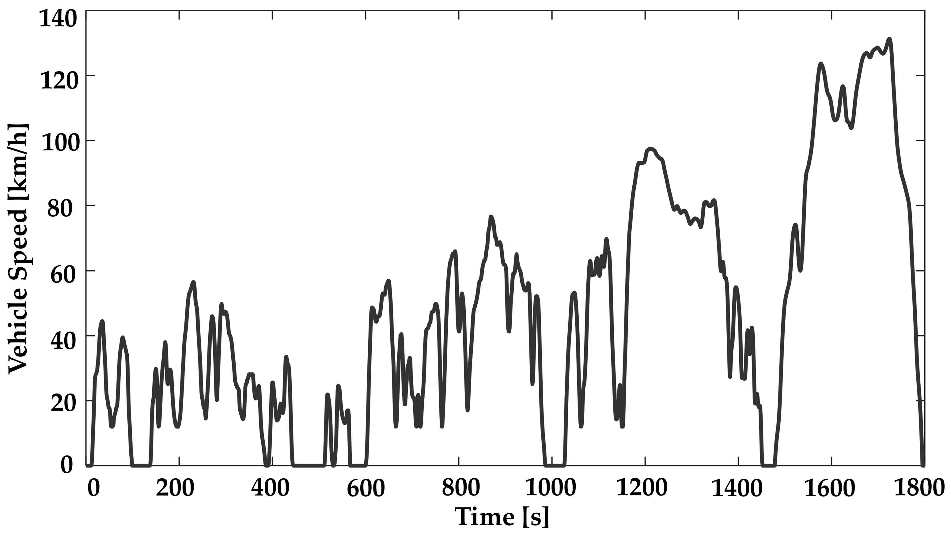
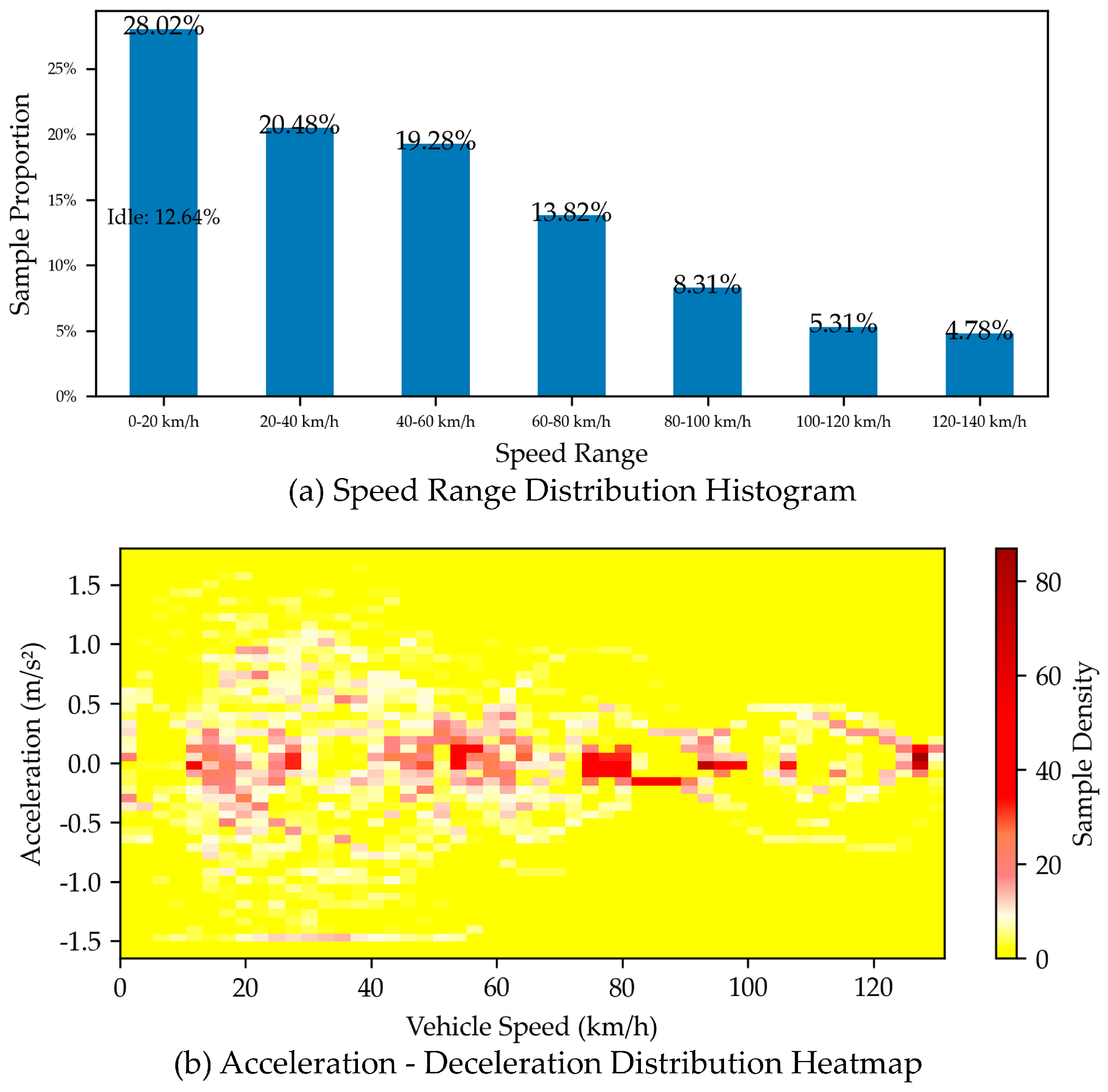
To fully train the neural network optimizer and enable it to possess strong generalization ability to adapt to complex and variable actual working conditions, the vehicle speed training data in the input features of this study are mainly collected from the WLTC (as shown in Figure 5). The WLTC (Worldwide Harmonized Light Vehicles Test Cycle), developed under the leadership of the United Nations Economic Commission for Europe, is an internationally widely adopted standard test cycle for evaluating vehicle emissions and energy consumption, and its test results are closer to real road driving conditions. To intuitively present the coverage characteristics of this cycle as training data, the numerical characteristics of the relevant data are shown in Table 2, and the visualization content is shown in Figure 6, including a speed interval distribution histogram and an acceleration–deceleration distribution heatmap, so as to clearly display the diversity of the data and the coverage range of dynamic characteristics.
In the speed interval distribution histogram of Figure 6a, the horizontal axis is divided into intervals such as 0–20 km/h and 20–40 km/h, up to 120–140 km/h, and the vertical axis represents the proportion of samples in each interval. It allows for an intuitive observation of the coverage of low-speed, medium-speed, high-speed, and idle conditions (with the proportion of idle conditions marked separately), fully reflecting that it is closer to real road driving states. The acceleration-deceleration heatmap in Figure 6b uses the horizontal axis to represent vehicle speed and the vertical axis to represent acceleration (including negative values for deceleration). The density of samples for different (speed-acceleration) combinations is reflected through the depth of colors, clearly showing the rich dynamic operation characteristics in the WLTC. These visualization results further verify the comprehensiveness of the WLTC in terms of vehicle speed range and acceleration-deceleration processes, providing high-quality data support for neural network training.
Sliding window processing (e.g., 6 s window) is mainly used for training data collection to ensure temporal continuity, enabling the network to learn dynamic change trends. Figure 7 shows the specific data extraction method.
The collection of training data is mainly based on the following aspects:
  • Sampling frequency setting: Under the WLTC, the initial state speed is sampled every 0.2 s to ensure the time resolution of the data; the reference speed sequence is sampled continuously for 10 steps with a time step of 0.6 s to capture the speed change trend during vehicle driving; meanwhile, the sampling interval for the initial state of battery SOC is set to 0.1 to ensure that changes in energy state are fully recorded.
  • Data extraction window: As shown by the gray box in the figure, the position of the data extraction window is determined according to vehicle speed information. Each window not only extracts the initial speed but also synchronously extracts the reference speed sequence within the future prediction horizon. This method ensures the temporal consistency of the data and enables the feature dimensions to fully reflect the dynamic characteristics of the vehicle.
  • Data integration and matching: After sampling each individual data stream, the speed, reference speed sequence, and initial state of battery SOC are integrated uniformly. During data integration, outliers and noise interference are removed, and interpolation and smoothing processing are adopted to ensure the temporal continuity and accuracy of the data, ultimately constructing a high-quality training dataset.
In addition, this study also introduces data normalization and standardization techniques to eliminate differences in dimensions between speed and battery SOC, and expands the data scale through data augmentation techniques to improve the robustness of the model.

3.3.2. Neural Network Architecture Design

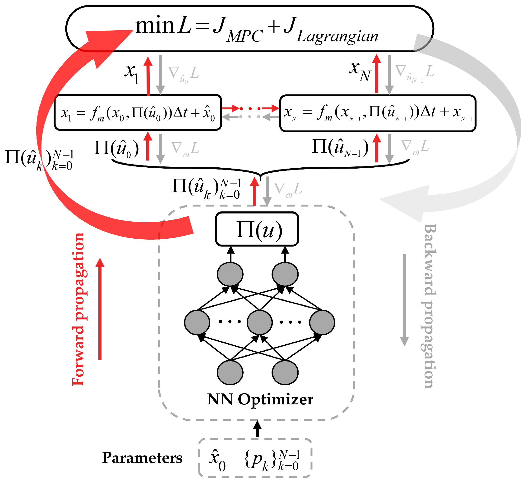
The network architecture is designed as shown in Figure 8, where red arrows represent the forward propagation path of the network, and gray arrows correspond to the backpropagation process based on the constructed objective function. The network input is the aforementioned driving scenario characteristic parameters { p k } k = 0 N 1 and initial state x ^ 0 . After forward propagation of the network, the control sequence u within the future prediction horizon is output. Through post-processing steps for the differentiability of control quantities, the network output sequence is mapped to the constraint space of control quantities. According to the aforementioned optimization problem and system dynamics equations, accurate prediction of the state quantities within the future prediction horizon is achieved. Based on this, the corresponding optimization problem is further constructed, including the original optimization problem and the soft penalty considering constraints. Finally, the network’s backpropagation mechanism is used to optimize the objective function, enabling network parameters to adapt to the corresponding optimization problem, thereby realizing the embedding of physical knowledge of the optimization problem. The network can achieve accurate prediction and optimization of control quantities based on a small amount of data.
Mapping relationship between network input and output: Based on the aforementioned MPC controller, the network input-output mapping relationship is constructed. The output of the network includes engine torque, motor torque, and transmission gear. The input of the network includes the current state variables of the system (such as speed v and battery SOC) and the reference speed sequence v r e f within the future prediction horizon. The specific relationship is
{ u ^ k } k = 0 N c 1 = f n n ( x ^ 0 , { p k } k = 0 N p 1 ) ,
where { u ^ k } k = 0 N c 1 is the output of the network, representing the control variables output by the MPC controller, and x ^ 0 , { p k } k = 0 N p 1 is the inputs of the network.
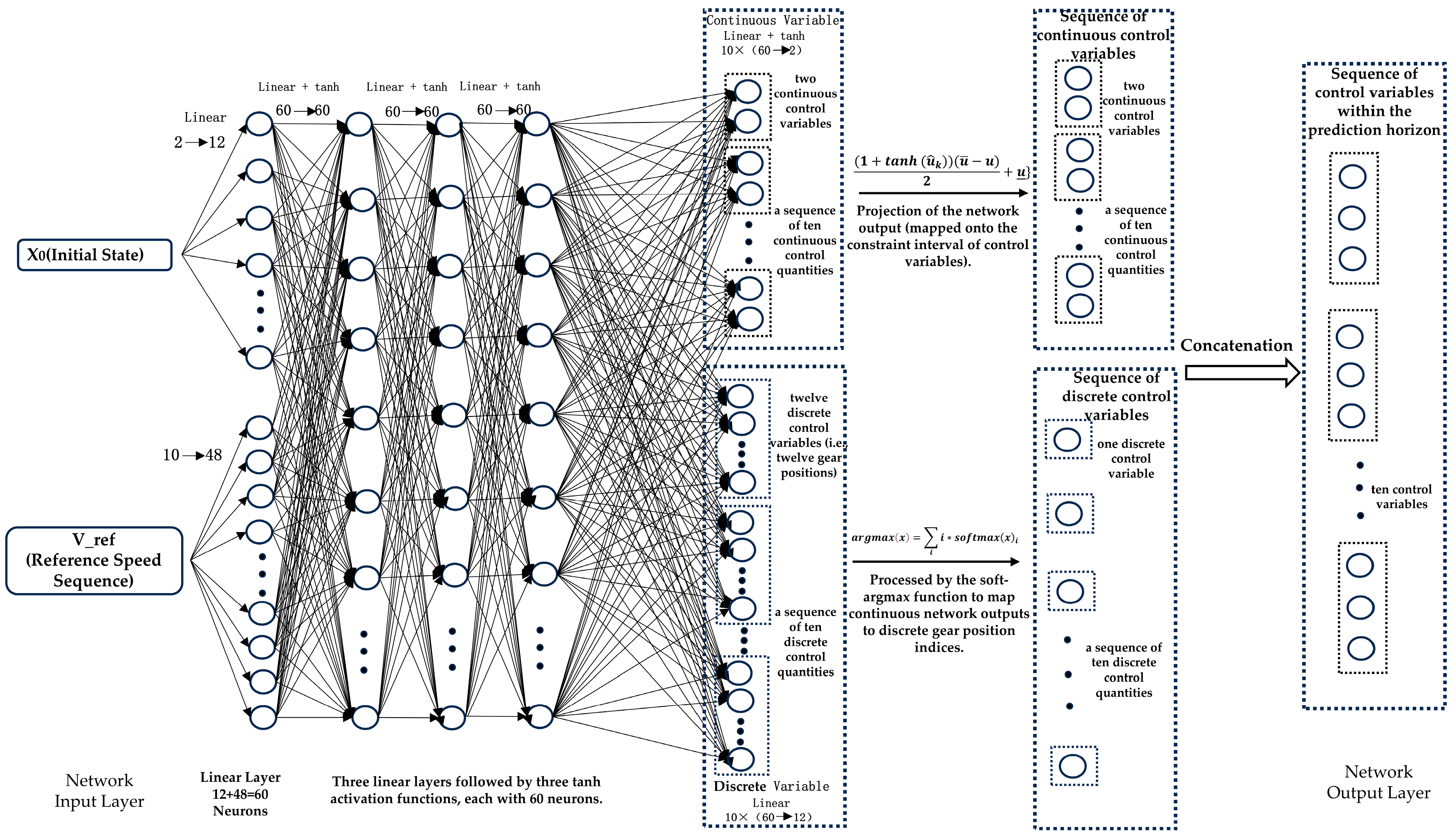
To fully capture the dynamic characteristics of the system, the network structure adopts a multi-layer fully connected neural network and introduces the nonlinear activation function tanh in the hidden layer to enhance the model’s ability to approximate complex nonlinear relationships. Meanwhile, a branch structure is designed to distinguish the processing of continuous and discrete control quantities.
Processing of network output control quantities: To meet actual physical and engineering constraints, the network output must be specially processed. According to the aforementioned MPC controller, the control quantities are engine torque, motor torque, and transmission gear. For continuous control variables (engine torque and motor torque), the network output sequence is mapped to the allowable interval of control quantities U = { u | u _ u u ¯ } through a nonlinear mapping function, as follows:
{ ( u ^ k ) } k = 0 N c 1 = 1 + tanh ( u ^ k ) ( u ¯ u ) 2 + u _ k = 0 N c 1 .
For the discrete variable of the gear, to maintain the differential differentiability of the entire network, this study introduces the soft-argmax function in the output layer to map continuous output values to integer gear information. This design not only ensures the differentiability of network output but also converts the discrete optimization problem into a continuous optimization problem using a smoothed approximation method, facilitating the solution of gradient descent algorithms. The specific processing method is as follows:
y = a r g m a x ( x ) = i i s o f t m a x ( x ) i .
System state update: The forward Euler method is used to realize state update within the prediction range. The obtained network output is sequentially applied to the system to obtain the state variable sequence within the prediction horizon. The state update process strictly satisfies the dynamic equation constraints
x k + 1 = x k + f ( x k , ( u ^ k ) ) Δ t ,
where f(⋅) represents the system state transition function, and Δ t is the prediction step.
Objective function: The construction of the PINN loss function needs to address two core demands.
L = J M P C + J L a g r a n g i a n ,
On one hand, it must deeply integrate the loss function defined in the MPC-based controller in Section 3.2. This function covers items such as fuel consumption, battery SOC deviation penalty, and speed tracking penalty, with the specific expression being
J M P C = ω 1 t 0 t f m ˙ f ( t ) d t + ω 2 J ( x v ) + ω 3 J ( x S O C ) ,
This part ensures the consistency of optimization objectives (e.g., energy saving, state tracking) with the traditional MPC framework, enabling the PINN output to inherit the guidance for the multi-objective optimization of the system.
On the other hand, it is necessary to ensure that the system’s state variables and control variables are within the constraint ranges. Meanwhile, due to the introduction of the neural network, the output of the network may be unreasonable in some cases, so constraints need to be added to the loss function to achieve a guiding effect. In this study, restrictions are mainly imposed on the gears. Simulation results without adding constraints show that the trained neural network controller outputs unreasonable gears at low vehicle speeds, that is, high gears are output at low speeds. To compensate for the transmission ratio corresponding to the high gears, the power system will output a larger torque. Although it can satisfy the dynamic constraints as a whole, it cannot achieve the energy-saving effect. Therefore, constraints are imposed on the gears when constructing the PINN loss function, meaning that the gear output is affected by the vehicle speed-low gears are preferred at low speeds, and high gears are used at high speeds. The specific form is as follows:
J L a g r a n g i a n = ω 4 G ( u g e a r , v r e f ) ,
G ( u g e a r , v r e f ) = u g e a r v r e f .
This constraint term guides the network to learn the physical law of “low gear at low speed and high gear at high speed” by penalizing the mismatch between high gear and low vehicle speed. Eventually, the augmented Lagrangian function can simultaneously achieve objective tracking and constraint satisfaction during the optimization process, reflecting the unique advantages of PINN in the optimization of hybrid systems.
Network parameter update: During training, the update of neural network parameters depends not only on the gradient information of the objective function but also on the gradient of physical constraint terms. Through automatic differentiation technology, the gradient of the loss function with respect to network parameters is calculated. As neural network parameters are updated, their output gradually converges to the optimal value of the optimization problem under given constraints. The following describes the process of updating neural network parameters and their impact on neural network output.
ω ( n + 1 ) = ω ( n ) η ω ( n ) L ,
where ω denotes the network parameters, η represents the learning rate, L is the objective function, and ω ( n ) L is the gradient of the objective function with respect to the network parameters.
Expressing the network output as u ^ ( θ ; ω ) , we have
u ^ ( θ , ω ( n + 1 ) ) = u ^ ( θ ; ω ( n ) + Δ ω ( n ) ) ,
where θ is the input to the neural network, and Δ ω ( n ) = η ω ( n ) L represents the change in the neural network parameters.
Expanding the above equation using a Taylor series, retaining only the first-order derivatives,
u ^ ( θ , ω ( n + 1 ) ) = u ^ ( θ ; ω ( n ) ) + J u ^ Δ ω ( n ) ,
where J u ^ is the Jacobian matrix with elements given by
( J u ^ ) i j = u ^ i ω j .
It can be inferred that, ω ( n ) L = J u ^ T u ^ L ,
u ^ ( θ , ω ( n + 1 ) ) = u ^ ( θ ; ω ( n ) ) η J u ^ J u ^ T u ^ L .
This matrix J u ^ J u ^ T can be regarded as a linear transformation of u ^ L .
Since x is a function of u ^ , u ^ L includes J x T x L , This implies that physical information is embedded into the neural network during the parameter update, where ( J x ) i j = x i x j .
In summary, the PINN-based neural network optimizer not only inherits the advantages of conventional MPC controllers in terms of objective tracking and constraint satisfaction but also enhances the characterization of the dynamic behavior of mixed systems by integrating physical information. This approach demonstrates higher robustness and accuracy in solving the optimization problem, thereby providing solid theoretical and methodological support for the implementation of energy management strategies in mixed systems.

3.3.3. Network Training (Offline Implementation Issues)

To facilitate understanding and verification of the network structure, Figure 9 shows a visual display of the network construction, which intuitively reflects the mapping relationship and information transmission process from the input layer, each hidden layer to the output layer.
In the network training phase, the current state of the vehicle (speed v and battery SOC) and the future reference speed sequence are first normalized, then concatenated and integrated after linear mapping to form the network initialization layer. Linear transformation and normalization techniques are used in this mapping process to ensure that each input signal can be effectively expressed on the same scale.
The overall network structure includes three hidden layers and one output layer. Each hidden layer consists of 60 neurons and uses the hyperbolic tangent (tanh) activation function to introduce nonlinear features, gradually abstracting the deep-level features of vehicle operation. The output layer is responsible for generating continuous and discrete control variable sequences within the prediction horizon, which are finally integrated to form the final control signal.
Since the input data do not contain explicit label information, the entire network is trained using an unsupervised learning method. During training, every 500 pieces of driving scenario feature data form a batch, and 4000 iterations are performed in total, making the cost function gradually converge and finally reach the expected training accuracy.

4. Simulation Verification and Discussion

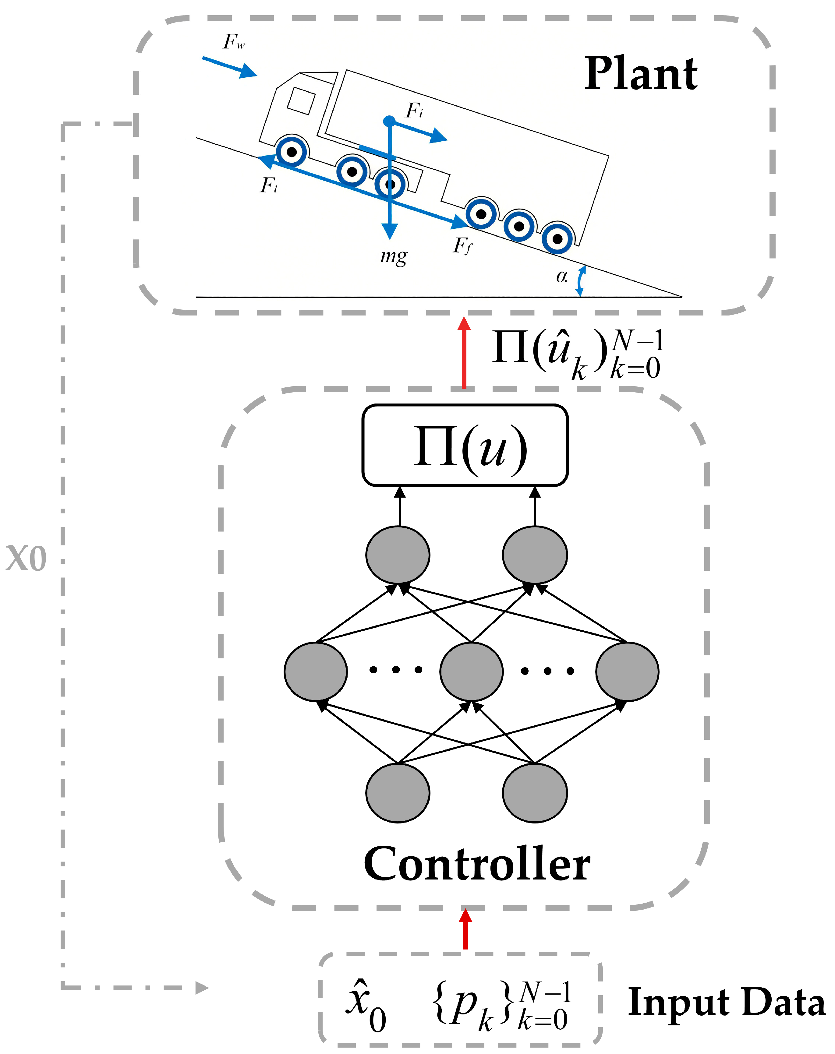
To verify the effectiveness of the proposed control algorithm, the neural network trained under the PyTorch (version 3.10) framework is used as a closed-loop controller for online simulation verification in the MATLAB/Simulink (version 2022a) environment. The neural network optimizer serves as the control core, and the vehicle model built in Simulink acts as the carrier for simulation verification. By inputting the initial state and the reference speed sequence within the prediction horizon, the network outputs corresponding control actions to reproduce the actual vehicle operation process, thereby evaluating the response and performance of the control strategy under different working conditions. The deployment form of the network is shown in Figure 10.

4.1. Online Simulation and Analysis

Our verification dataset is independent of the training dataset, and two segments of real vehicle data conditions are used for test verification. The objective function set by PINN is consistent with that defined by the MPC algorithm, and the trained neural network optimizer is compared with the open-source mixed-integer solver BONMIN (version casadi 3.6.7).
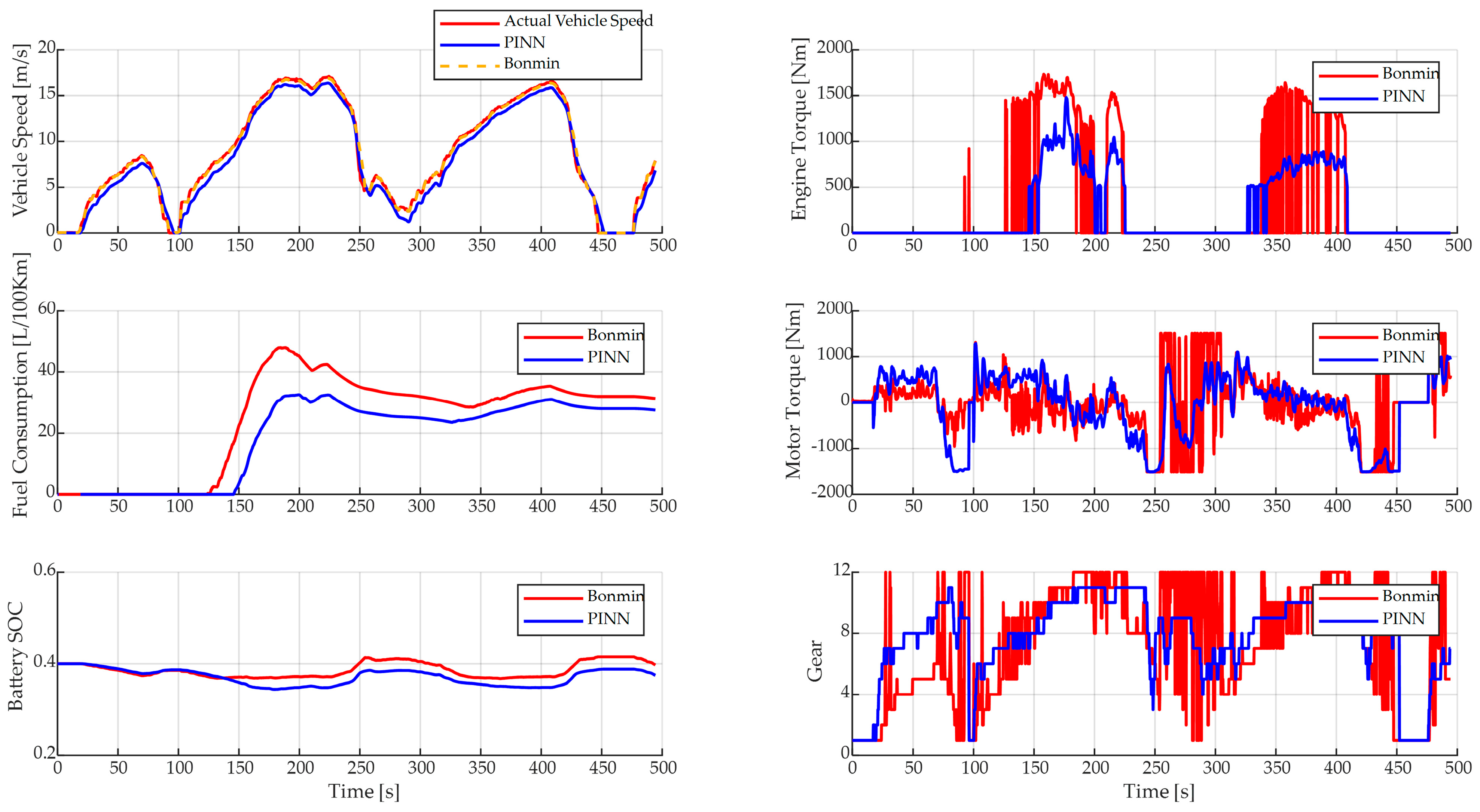
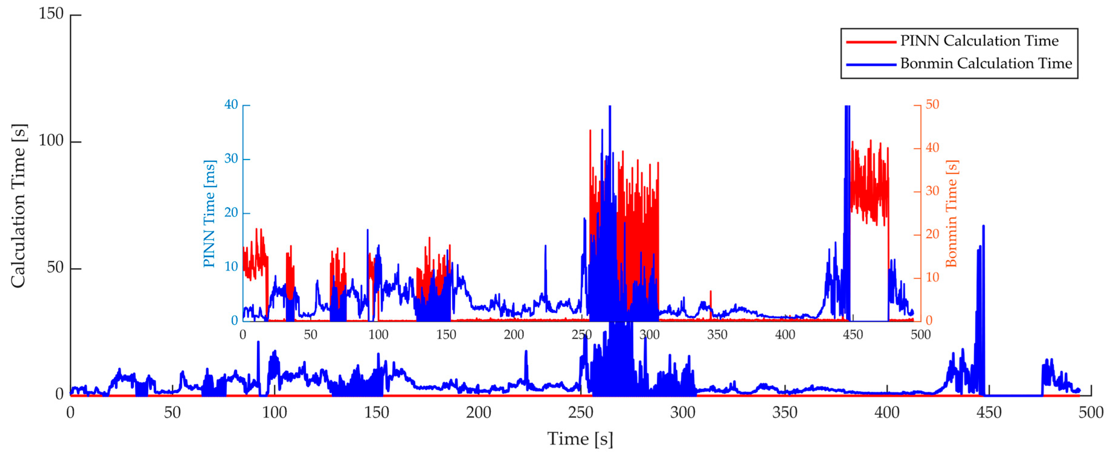
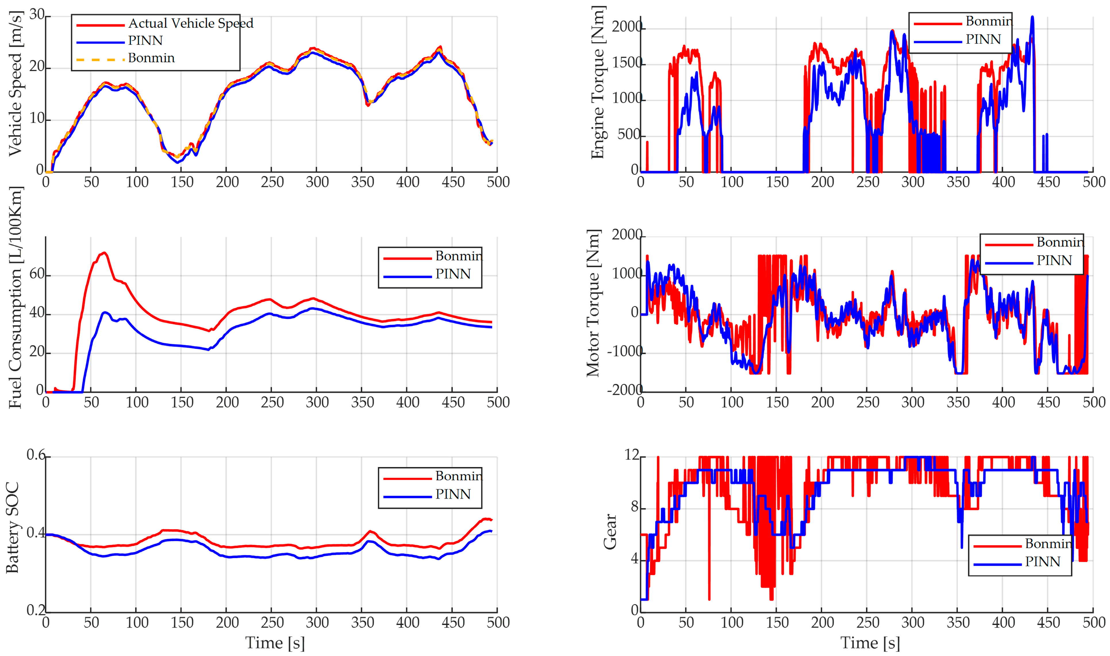
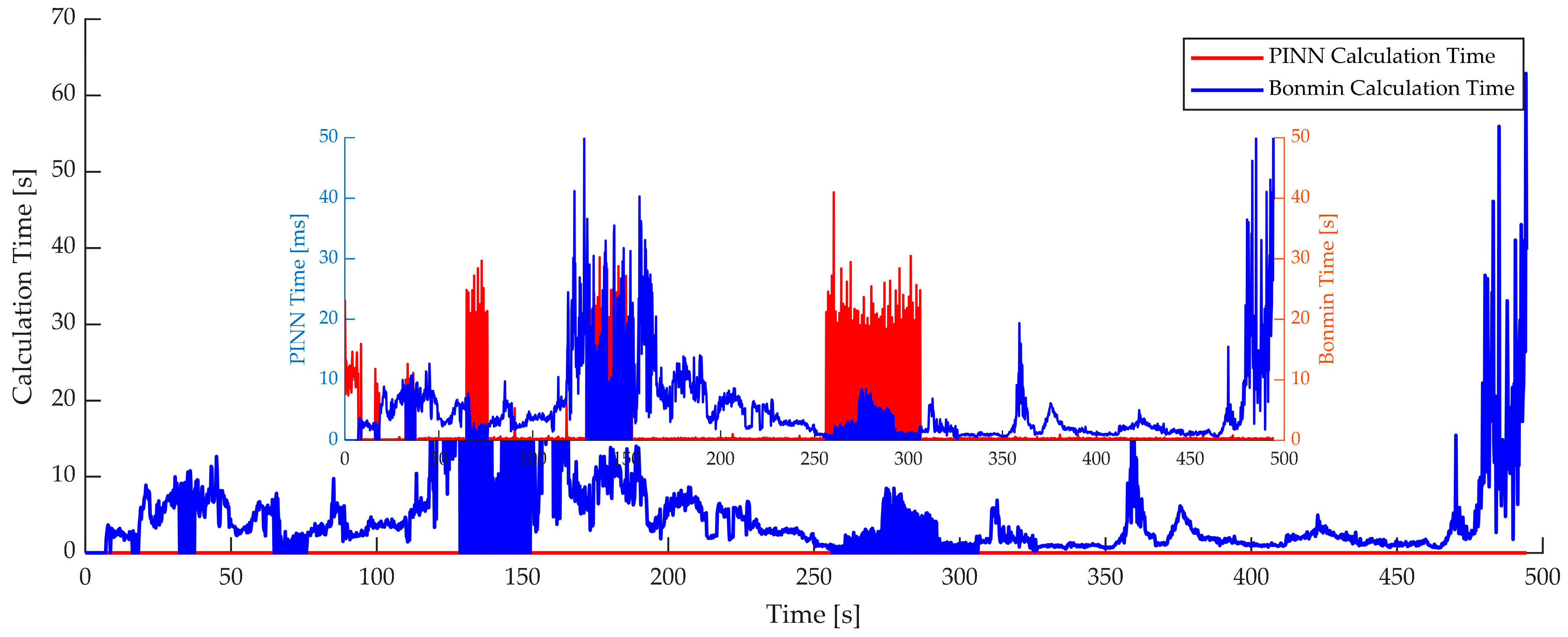
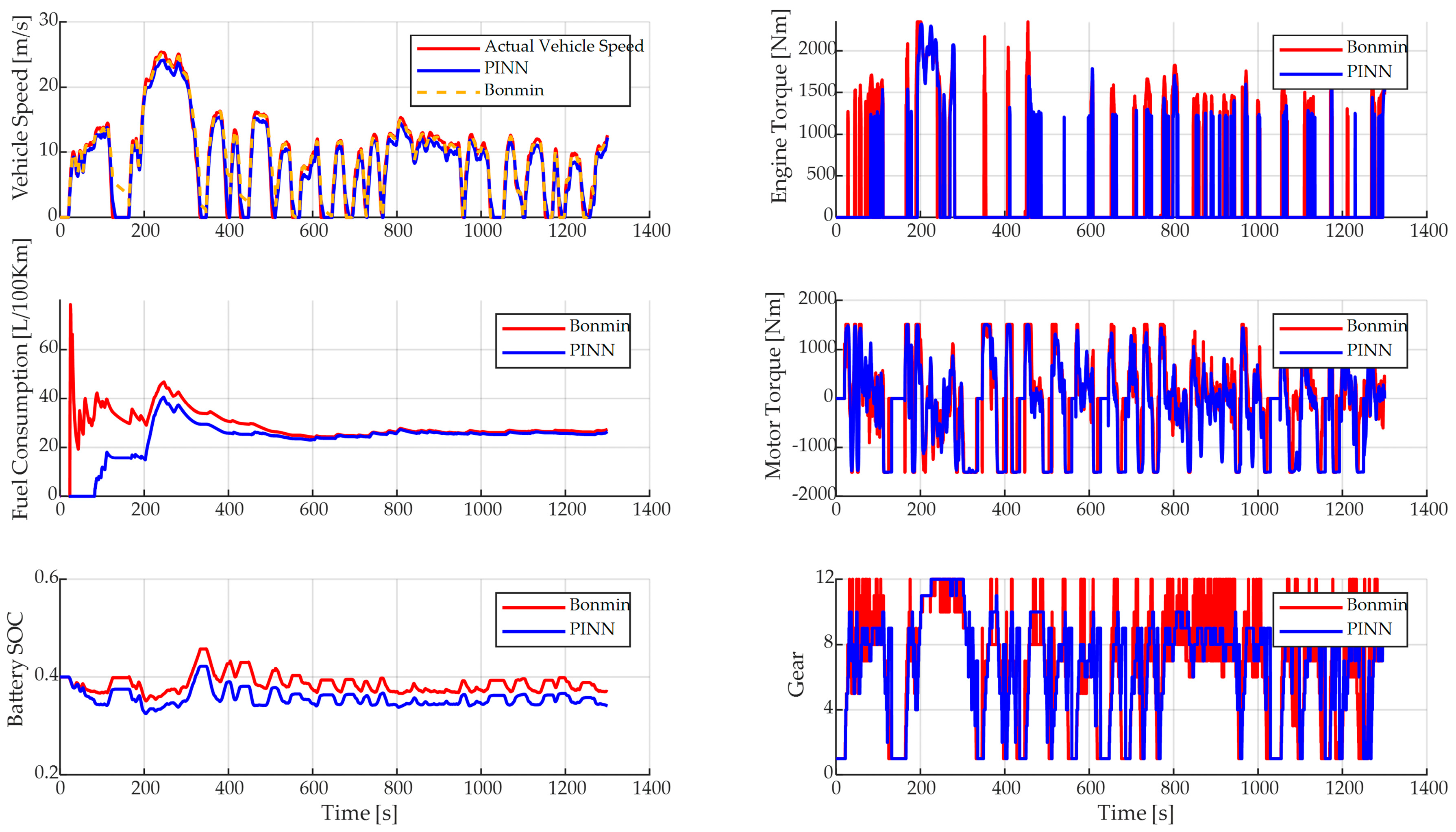
In the two segments of test data, the initial speed is 0, and the average speeds are 8.49 m/s and 15.24 m/s, respectively. Each segment of the working condition includes acceleration, deceleration, and parking, fully verifying the control effect of the network optimizer. Comparisons and analyses are conducted in terms of speed tracking, energy consumption, control performance, and computation time. Figure 11, Figure 12, Figure 13 and Figure 14 and Table 3 show the verification results under the two real vehicle working conditions.
It can be found that the solving effect of the neural network optimizer is similar to that of BONMIN, with similar torque fluctuation ranges and gears, small differences in SOC curve changes, and good speed tracking effect. And the simulation results reveal that the PINN-based controller achieves energy consumption deviations of only 0.9% and 0.25% under two distinct real-world driving conditions when compared with the BONMIN solver, which is regarded as a benchmark for theoretical optimal performance. These minor deviations indicate that the proposed method exhibits strong approximation accuracy while significantly reducing computational overhead.
The major reason for this computational efficiency is that the PINN optimizer, being trained offline, replaces iterative solving procedures with direct matrix operations such as multiplications and additions during online inference. Once the vehicle state is acquired from sensors, the neural network can rapidly output control decisions through feedforward computation, eliminating the need for repeated evaluations of Jacobian or Hessian matrices as required by traditional solvers like BONMIN.
This reduction in algorithmic complexity allows the PINN controller to operate at millisecond-level response times (approximately 2 ms), compared to several seconds for BONMIN (averaging 4–5 s), thereby fully satisfying the real-time requirements of in-vehicle control systems. In practical terms, the small energy deviation translates to marginal fuel consumption differences, yet brings substantial gains in computational efficiency and feasibility for embedded deployment in hybrid electric commercial vehicles.
To further evaluate the robustness and adaptability of the proposed control strategy, we conducted an additional online simulation under UDDS (urban dynamometer driving schedule) working condition. Unlike the previous driving scenarios, the UDDS is characterized by high-frequency power fluctuations, rapid acceleration and deceleration, and a higher proportion of idling periods, making it a more challenging test for control algorithms. Figure 15 and Table 4 show the verification results under the UDDS working conditions.
The results show that the equivalent fuel consumption of the PINN-MPC strategy under the UDDS is 29.626 L/100 km, with an error of only 1.91% compared to 29.0694 L/100 km for the BONMIN solver-well within the acceptable deviation threshold of 2%. Even under long-term, high-frequency dynamic demands, the optimization accuracy remains stable.
In terms of computational efficiency, the PINN-MPC method maintains real-time capability, with an average solution time of 3.3 ms and a maximum delay of 43 ms, significantly outperforming BONMIN’s average 3.135 s and maximum 111.2 s.
Overall, this robustness test under the UDDS cycle demonstrates that the proposed controller not only adapts well to complex and unseen driving profiles, but also retains its computational and optimization advantages. These results further reinforce the potential of PINN-MPC for deployment in practical engineering scenarios involving diverse vehicle operations.

4.2. HIL Test

The hardware-in-the-loop (HIL) test is conducted on two real-time target machines (Speedgoat platforms), as shown in the figure. Firstly, all algorithm models, commercial vehicle object models, and driving scenarios are built in MATLAB/SIMULINK. Secondly, the algorithm is downloaded to Speedgoat 1, and the commercial vehicle object model and driving scenarios are downloaded to Speedgoat 2. The two Speedgoat devices realize interactive transmission of input and output variables between the controller and the vehicle model through CAN communication. Correspondingly, two personal computers (PCs) are connected to the two Speedgoat devices for observing and recording test results. The HIL test platform is shown in Figure 16.
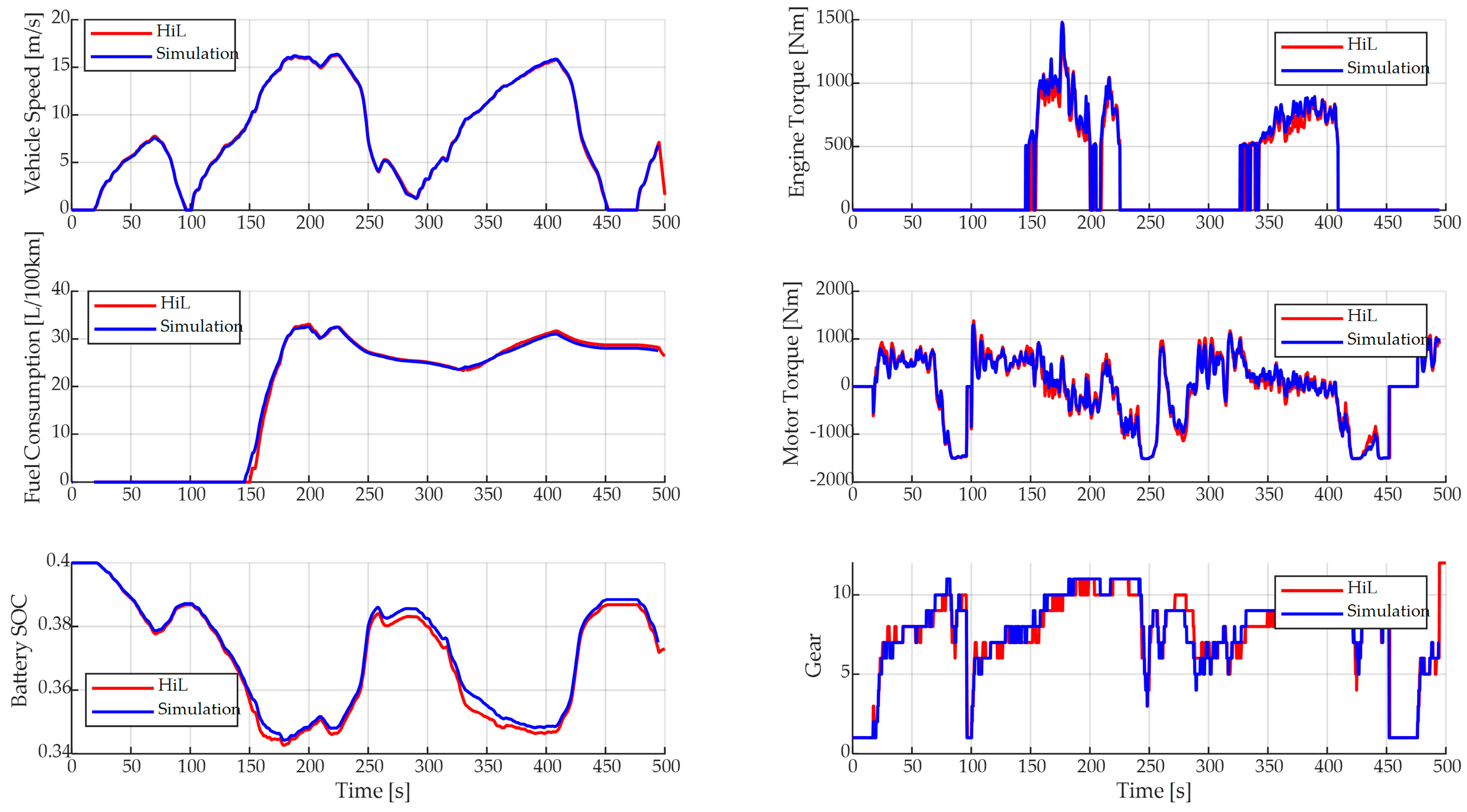
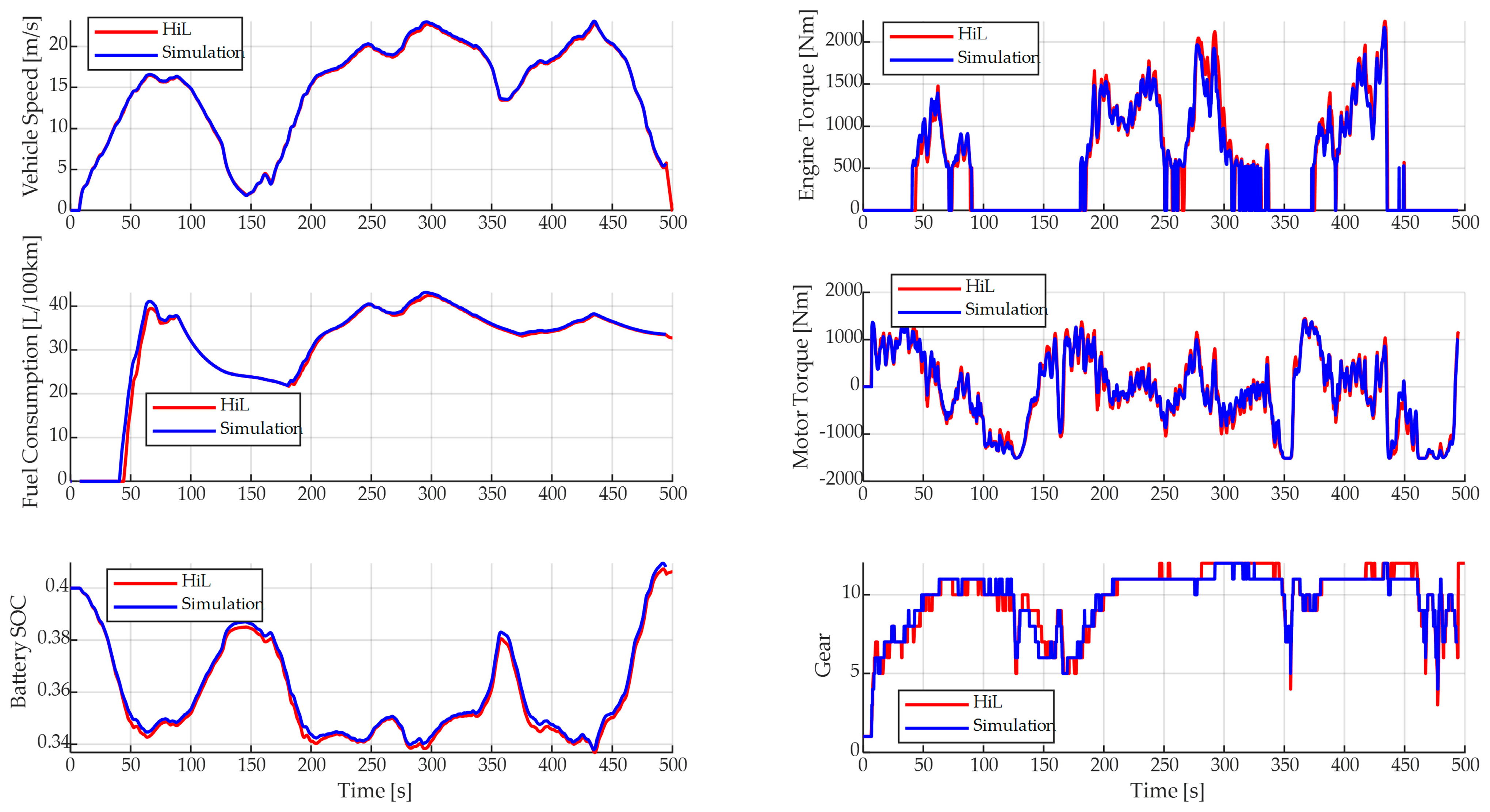
The HIL tests conducted in this study are based on the two real-world driving conditions described in Section 4.1, which were collected from actual vehicle operations. These driving cycles include acceleration, deceleration, and idle phases, and serve as representative scenarios for validating the real-time control capability of the proposed strategy in realistic traffic environments.
The HIL results are shown in Figure 17 and Figure 18. By comparing the HIL test results with the online simulation results, it is found that the control effect of the HIL test is basically consistent with that of the online simulation, further verifying that the neural network optimizer can be implemented on vehicle-grade controllers, meeting real-time requirements without sacrificing energy-saving effects.
To further verify the consistency and real-time applicability of the proposed controller, we conducted a detailed quantitative comparison between the HIL test and the online simulation results. Table 5 summarizes key metrics including average vehicle speed, equivalent fuel consumption, computation time, and energy consumption error under two real-world driving conditions. The results demonstrate that the HIL test closely aligns with the simulation, with fuel consumption deviations of less than 0.25% and control cycle response times within a few milliseconds. This confirms the reliability and stability of the controller across testing environments.
Additionally, the performance of the deployed controller on a Speedgoat real-time platform (Intel i7 CPU, 16 GB RAM) was profiled to assess its resource utilization. The manufacturer of Speedgoat equipment is Speedgoat GmbH, with its headquarters located in Bern, Switzerland. As presented in Table 6, the controller operates with a CPU usage of approximately 30% and memory usage of 1–2 GB, and maintains a 100% control cycle execution rate without overflow or delay. These results indicate that the PINN-MPC method demonstrates excellent computational efficiency and stability, and is well-suited for deployment on resource-constrained embedded systems in practical commercial vehicles.

5. Conclusions

In this work, an energy management strategy based on neural network-optimized model predictive control (NN-MPC) is proposed, and a series of in-depth investigations are conducted to address the challenges of real-time control and computational efficiency in energy management strategies for hybrid commercial vehicles. The study demonstrates that the NN-MPC method, by embedding physical information into the neural network and employing a soft-argmax function to handle discrete gear variables, not only achieves efficient solution of mixed-integer programming problems but also significantly reduces online solution time, thereby remarkably enhancing the system’s real-time response capability.
Results from online simulations and HIL experiments validate that under two real vehicle driving conditions, compared with traditional mixed-integer solvers, the fuel economy remains nearly identical, while the solution time is reduced from an average of 10 s to approximately 5 ms. This clearly highlights the application advantages of NN-MPC in real-time energy management, providing an efficient and precise solution for online control of hybrid commercial vehicles.
Overall, this work demonstrates the great potential of the NN-MPC method in addressing real-time control issues of complex systems. It not only offers new research insights for the development of energy management technologies for hybrid vehicles but also lays a solid foundation for the future engineering implementation of this technology. Future research will further expand the adaptability of the method under various operating conditions and explore its integration with other advanced control strategies to achieve higher-level energy management performance.
In terms of comparative evaluation, this study primarily validates the accuracy and efficiency of the proposed PINN-based method by comparing it with the mature mixed-integer programming solver BONMIN. While most existing neural network-based strategies focus on continuous control or a single discrete variable, the proposed approach explicitly addresses the challenge of mixed-integer optimization in hybrid energy management. Simulation and HIL test results show that the PINN method achieves comparable fuel economy and control performance (with an error less than 1%) while significantly reducing the average computation time from seconds to milliseconds.
In future work, we plan to extend the comparison to other neural network-based optimization frameworks, particularly those designed for real-time applications with discrete variables. If relevant models become available or can be adapted for this problem class, we will conduct additional comparative studies to further verify the performance and robustness of the proposed PINN approach.

Author Contributions

Conceptualization, J.H.; Methodology, X.L.; Software, F.Y.; Validation, F.Y., X.L. and X.N.; Formal analysis, X.N. and H.C.; Investigation, H.C. and M.T. All authors have read and agreed to the published version of the manuscript.

Funding

This work was partly supported by the National Natural Science Foundation of China under Grants 62473291, Guangdong Basic and Applied Basic Research Foundation under Grant 2022A1515110591, Shenzhen Stable Supporting Project under Grant 20220718111409001 and Fundamental Research Funds for the Central Universities.

Data Availability Statement

The original contributions presented in this study are included in the article. Further inquiries can be directed to the corresponding author.

Conflicts of Interest

The authors declare no conflicts of interest.

References

  1. Letnik, T.; Farina, A.; Mencinger, M.; Lupi, M. Božičnik, S. Dynamic management of loading bays for energy efficient urban freight deliveries. Energy 2018, 159, 916–928. [Google Scholar] [CrossRef]
  2. Kast, J.; Vijayagopal, R.; Gangloff, J.; Marcinkoski, J. Clean commercial transportation: Medium and heavy duty fuel cell electric trucks. Int. J. Hydrogen Energy 2017, 42, 4508–4517. [Google Scholar] [CrossRef]
  3. Ard, T.; Guo, L.; Han, J.; Jia, Y.; Vahidi, A.; Karbowski, D. Energy-Efficient Driving in Connected Corridors via Minimum Principle Control: Vehiclein-the-Loop Experimental Verification in Mixed Fleets. IEEE Trans. Intell. Veh. 2023, 8, 1279–1291. [Google Scholar] [CrossRef]
  4. Anselma, P.G.; Kollmeyer, P.J.; Feraco, S.; Bonfitto, A.; Belingardi, G.; Emadi, A.; Amati, N.; Tonoli, A. Economic payback time of battery pack replacement for hybrid and plug-in hybrid electric vehicles. IEEE Trans. Transp. Electrific. 2023, 9, 1021–1033. [Google Scholar] [CrossRef]
  5. Zhang, Y.; Chen, Z.; Li, G.; Liu, Y.; Huang, Y. A novel model predictive control based co-optimization strategy for velocity planning and energy management of intelligent PHEVs. IEEE Trans. Veh. Technol. 2022, 71, 12667–12681. [Google Scholar] [CrossRef]
  6. Herrera, V.I.; Milo, A.; Gaztañaga, H.; Ramos, J.; Camblong, H. Adaptive and non-adaptive strategies for optimal energy management and sizing of a dual storage system in a hybrid electric bus. IEEE Trans. Intell. Transp. Syst. 2019, 20, 3435–3447. [Google Scholar] [CrossRef]
  7. Shi, C.; Wang, T.; Liao, X.; Qie, B.; Yang, P.; Chen, M.; Wang, X.; Srinivasan, A.; Cheng, Q.; Ye, Q.; et al. Accordion-like stretchable Li-ion batteries with high energy density. Energy Storage Mater. 2019, 17, 136–142. [Google Scholar] [CrossRef]
  8. Hadjigeorgiou, A.; Timotheou, S. Real-Time Optimization of FuelConsumption and Travel-Time of CAVs for Cooperative Intersection Crossing. IEEE Trans. Intell. Veh. 2023, 8, 313–329. [Google Scholar] [CrossRef]
  9. Fayaz, M.; Khan, J.; Bilal, M. Effectual Energy Consumption and User Comfort Optimization Based on Dynamic User Set Parameters in Electric Vehicles. IEEE Trans. Intell. Veh. 2023, 9, 178–189. [Google Scholar] [CrossRef]
  10. Ghandriz, T.; Jacobson, B.; Murgovski, N.; Nilsson, P.; Laine, L. Real-time predictive energy management of hybrid electric heavy vehicles by sequential programming. IEEE Trans. Veh. Technol. 2021, 70, 4113–4128. [Google Scholar] [CrossRef]
  11. Sehla, K.; Nguyen, T.M.T.; Pujolle, G.; Velloso, P.B. Resource allocation modes in C-V2X: FromLTE-V2X to 5G-V2X. IEEE Internet Things J. 2022, 9, 8291–8314. [Google Scholar] [CrossRef]
  12. Hou, S.; Chen, H.; Yin, H.; Zhao, J.; Xu, F.; Gao, J. Energy Management Based on Mixed-Integer Nonlinear Model Predictive Control for Hybrid Electric Vehicles. IEEE Trans. Intell. Transp. Syst. 2024, 25, 17432–17451. [Google Scholar] [CrossRef]
  13. Zhang, F.; Xi, J.; Langari, R. Real-Time Energy Management Strategy Based on Velocity Forecasts Using V2V and V2I Communications. IEEE Trans. Intell. Transp. Syst. 2017, 18, 416–430. [Google Scholar] [CrossRef]
  14. Peng, J.; He, H.; Xiong, R. Rule based energy management strategy for a series–parallel plug-in hybrid electric bus optimized by dynamic programming. Appl. Energy 2017, 185, 1633–1643. [Google Scholar] [CrossRef]
  15. Phan, D.; Bab-Hadiashar, A.; Fayyazi, M.; Hoseinnezhad, R.; Jazar, R.N.; Khayyam, H. Interval type 2 fuzzy logic control for energy management of hybrid electric autonomous vehicles. IEEE Trans. Intell. Veh. 2020, 6, 210–220. [Google Scholar] [CrossRef]
  16. Kamal, E.; Adouane, L. Intelligent energy management strategy based on artificial neural fuzzy for hybrid vehicle. IEEE Trans. Intell. Veh. 2018, 3, 112–125. [Google Scholar] [CrossRef]
  17. He, Y.; Zhou, Q.; Makridis, M.; Mattas, K.; Li, J.; Williams, H.; Xu, H. Multiobjective co-optimization of cooperative adaptive cruise control and energy management strategy for PHEVs. IEEE Trans. Transp. Electrif. 2020, 6, 346–355. [Google Scholar] [CrossRef]
  18. Hu, Q.; Amini, M.R.; Kolmanovsky, I.; Sun, J.; Wiese, A.; Seeds, J.B. Multihorizon model predictive control: An application to integrated power and thermal management of connected hybrid electric vehicles. IEEE Trans. Control. Syst. Technol. 2022, 30, 1052–1064. [Google Scholar] [CrossRef]
  19. Dong, S.; Chen, H.; Gao, B.; Guo, L.; Liu, Q. Hierarchical Energy-Efficient Control for CAVs at Multiple Signalized Intersections Considering Queue Effects. IEEE Trans. Intell. Transp. Syst. 2022, 23, 11643–11653. [Google Scholar] [CrossRef]
  20. Mei, P.; Karimi, H.R.; Xie, H.; Chen, F.; Huang, C.; Yang, S. A deep reinforcement learning approach to energy management control with connected information for hybrid electric vehicles. Eng. Appl. Artif. Intell. 2023, 123, 106239. [Google Scholar] [CrossRef]
  21. Cui, N.; Cui, W.; Shi, Y. Deep reinforcement learning based PHEV energy management with co-recognition for traffic condition and driving style. IEEE Trans. Intell. Veh. 2023, 8, 3026–3039. [Google Scholar] [CrossRef]
  22. Hou, S.; Yin, H.; Xu, F.; Benjamín, P.; Gao, J.; Chen, H. Multihorizon predictive energy optimization and lifetime management for connected fuel cell electric vehicles. Energy 2023, 266, 126466. [Google Scholar] [CrossRef]
  23. Ali, A.M.; Moulik, B.; Söffker, D. Intelligent real-time power management of multi-source HEVs based on driving state recognition and offline optimization. IEEE Trans. Intell. Transp. Syst. 2023, 24, 247–257. [Google Scholar] [CrossRef]
  24. Maamria, D.; Gillet, K.; Colin, G.; Chamaillard, Y.; Nouillant, C. Computation of ECO-driving cycles for hybrid electric vehicles: Comparative analysis. Control Eng. Pract. 2018, 71, 44–52. [Google Scholar] [CrossRef]
  25. Chowdhri, N.; Ferranti, L.; Iribarren, F.S.; Shyrokau, B. Integrated nonlinear model predictive control for automated driving. Control Eng. Pract. 2021, 106, 104654. [Google Scholar] [CrossRef]
  26. Wang, H.; Liu, B.; Ping, X.; An, Q. Path Tracking Control for Autonomous Vehicles Based on an Improved MPC. IEEE Access 2019, 7, 161064–161073. [Google Scholar] [CrossRef]
  27. Anselma, P.G. Dynamic programming based rapid energy management of hybrid electric vehicles with constraints on smooth driving, battery state-of-charge and battery state-of-health. Energies 2022, 15, 1665. [Google Scholar] [CrossRef]
  28. Liu, Q.; Wei, J.; Sun, H.; Lin, Y.; Xu, S.; Liu, D. Smulation study on predictive cruise control strategy for an electric heavy duty trucks. In Proceedings of the 2021 IEEE Sustainable Power and Energy Conference, Nanjing, China, 23–25 December 2021; pp. 3593–3597. [Google Scholar]
  29. Shen, M.H.; Dollar, R.A.; Molnar, T.G.; He, C.R.; Vahidi, A.; Orosz, G. EnergyEfficient Reactive and Predictive Connected Cruise Control. IEEE Trans. Intell. Veh. 2023, 9, 944–957. [Google Scholar] [CrossRef]
  30. Hong, J.; Luo, X.; Wu, H.; Na, X.; Chu, H.; Gao, B.; Chen, H. Energy-Saving Driving Assistance System Integrated With Predictive Cruise Control for Electric Vehicles. IEEE Trans. Intell. Veh. 2024, 9, 4518–4528. [Google Scholar] [CrossRef]
  31. Dong, S.; Ghezzi, A.; Harzer, J.; Frey, J.; Gao, B.; Chen, H.; Diehl, M. Real-Time NMPC With Convex–Concave Constraints and Application to Eco-Driving. IEEE Trans. Control. Syst. Technol. 2025, 33, 807–814. [Google Scholar] [CrossRef]
  32. Li, Y.; Zhao, Z.; Wu, J.; Huo, W.; He, H.; Chen, Y. Multi-Vehicle InteractionAware Energy Management for Connected Hybrid Electric Vehicles via Deep Reinforcement Learning. In Proceedings of the 2024 IEEE 14th International Conference on CYBER Technology in Automation, Control, and Intelligent Systems (CYBER), Copenhagen, Denmark, 16–19 July 2024; pp. 434–439. [Google Scholar]
  33. Zhang, H.; Peng, J.; Dong, H.; Ding, F.; Tan, H. Integrated velocity optimization and energy management strategy for hybrid electric vehicle platoon: A multi-agent reinforcement learning approach. IEEE Trans. Transp. Electrif. 2023, 10, 2547–2561. [Google Scholar] [CrossRef]
  34. Luo, X.; Dong, S.; Hong, J.; Wang, X.; Gao, B.; Chen, H. Online Ecological Gearshift Strategy via Neural Network with Soft-Argmax Operator. IFAC-PapersOnLine 2024, 50, 415–420. [Google Scholar] [CrossRef]
  35. Shi, W.; Luo, X.; Hong, J.; Zhao, C.; Gao, B.; Chen, H. Accelerating Model Predictive Control with Neural Network Optimizer. In Proceedings of the 2023 7th CAA International Conference on Vehicular Control and Intelligence (CVCI), Changsha, China, 27–29 October 2023; pp. 1–7. [Google Scholar]
Figure 1. P2 configuration hybrid electric vehicle.
Electronics 14 03176 g001
Figure 2. Longitudinal vehicle dynamic.
Electronics 14 03176 g002
Figure 3. Engine universal characteristic map.
Electronics 14 03176 g003
Figure 4. Motor universal characteristic map.
Electronics 14 03176 g004
Figure 5. WLTC.
Figure 5. WLTC.
Electronics 14 03176 g005
Figure 6. Visualization of WLTC working condition data.
Electronics 14 03176 g006
Figure 7. The specific data extraction method.
Electronics 14 03176 g007
Figure 8. The network architecture.
Electronics 14 03176 g008
Figure 9. The visual display of the network construction.
Electronics 14 03176 g009
Figure 10. The deployment form of the network.
Electronics 14 03176 g010
Figure 11. Simulation results of first driving cycle.
Electronics 14 03176 g011
Figure 12. Calculation time of first driving cycle.
Electronics 14 03176 g012
Figure 13. Simulation results of second driving cycle.
Electronics 14 03176 g013
Figure 14. Calculation time of second driving cycle.
Electronics 14 03176 g014
Figure 15. Calculation time of UDDS driving cycle.
Electronics 14 03176 g015
Figure 16. HIL test platform.
Electronics 14 03176 g016
Figure 17. HIL results of first driving cycle.
Electronics 14 03176 g017
Figure 18. HIL results of second driving cycle.
Electronics 14 03176 g018
Table 1. Comparison between the General MIP-MPC Algorithm and the PINN-MPC Algorithm.
State Update MethodLoss FunctionSolution Method
General MIP-MPC AlgorithmSystem state equationDetermined by control objectivesBranch and bound
PINN-MPC
Algorithm
System state equationDetermined not only by control objectives, but also with the addition of restrictions on state variables and control variables to guide trainingUsing neural network parameters for matrix operations
Table 2. WLTC characteristics.
ParameterValue
Total Duration1800 s
Total Distance23.27 km
Average Speed46.5 km/h
Maximum Speed131.3 km/h
Idling Time Ratio13.40%
Frequency of Acceleration/DecelerationSimilar to real traffic conditions
Table 3. Comparison of simulation results of two real vehicle working condition data.
The First Condition
Average speed
(actual vehicle speed, 8.489 m/s)
Equivalent fuel consumption (L/100 km)Average calculation time (s)Maximum calculation time (s)Energy consumption error
BONMIN solver8.47831.73384.456142.80.90%
PINN solver8.20232.0192.83 × 10−30.0354
The Second Condition
Average speed
(actual vehicle speed, 15.33 m/s)
Equivalent fuel consumption (L/100 km)Average calculation time (s)Maximum calculation time (s)Energy consumption error
BONMIN solver15.2632.69815.03762.920.25%
PINN solver14.9732.77941.27 × 10−30.041
Table 4. Comparison of simulation results of UDDS working condition.
Average Speed (m/s)Equivalent Fuel
Consumption
(L/100 km)
Average
Calculation Time (s)
Maximum
Calculation Time (s)
Energy
Consumption
Error
BONMIN solver8.9829.0693.135111.21.91%
PINN solver8.7729.6263.3 × 10−30.043
Table 5. Comparison between the HIL test and the online simulation results.
The First Condition
Average speed (m/s)Equivalent fuel consumption (L/100 km)Average calculation time (s)Maximum calculation time (s)Energy consumption error
Online Simulation8.20232.0190.00280.03540.60%
HIL Test8.18832.2380.00320.0038
The Second
Condition
Average speed (m/s)Equivalent fuel consumption (L/100 km)Average calculation time (s)Maximum calculation time (s)Energy consumption error
Online Simulation14.9732.77940.00130.0410.14%
HIL Test14.8432.82520.00350.004
Table 6. Hardware resource usage.
IndicatorValueDescription
CPU UtilizationAround 30%Maximum load within a single control cycle
Memory Usage1–2 GBIncludes neural network weights and cache
Control Cycle Execution Rate100%Successfully executed per cycle, no overflow or lag
Disclaimer/Publisher’s Note: The statements, opinions and data contained in all publications are solely those of the individual author(s) and contributor(s) and not of MDPI and/or the editor(s). MDPI and/or the editor(s) disclaim responsibility for any injury to people or property resulting from any ideas, methods, instructions or products referred to in the content.