Abstract
This article presents a comprehensive modeling and simulation framework for a capacitive MEMS accelerometer integrated with a sigma-delta analog-to-digital converter (ADC), with a focus on applications in wearable health and motion monitoring devices. The accelerometer used in the system is connected to a smartphone equipped with dedicated software and will be used to assess the risk of falling, which is crucial for patients with balance disorders. The authors designed the accelerometer with special attention paid to the specification required in a system, where the acceleration is ±2 g and the frequency is 100 Hz. They investigated the sensor’s behavior in the DC, AC, and time domains, capturing both the mechanical response of the proof mass and the resulting changes in output capacitance due to external acceleration. A key component of the simulation is the implementation of a second-order sigma-delta modulator designed to digitize the small capacitance variations generated by the sensor. The Simulink model includes the complete signal path from analog input to quantization, filtering, decimation, and digital-to-analog reconstruction. By combining MEMS+ modeling with MATLAB-based system-level simulations, the workflow offers a fast and flexible alternative to traditional finite element methods and facilitates early-stage design optimization for MEMS sensor systems intended for real-world deployment.
1. Introduction
Smart electronic systems are currently one of the most growing branches of electronics. They are used in smartphones, tablets, drones, etc. They control everyday things such as lighting, window blinds, garage doors, etc., creating the Internet of Things (IoT) [1]. We can find them also in specialized equipment such as medical devices that make life easier for patients with various diseases at home. We can also find them in healthcare applications used by medical personnel in health centers. They use rapidly developing microelectromechanical systems (MEMSs), especially in activity sensors, biosensors, chemical sensors, microfluidic diagnostics, drug delivery devices, gene analyzers, etc. [2,3]. Thanks to them, medical diagnostic is faster and easier compared to previously used devices. The small medical devices used by patients are usually connected to smartphones that collect data and send it to health centers, where doctors can monitor the patient’s health in real time and provide appropriate treatment immediately.
We may find many interesting usages of the MEMS sensors in wearable applications. In [4] the authors presented a wearable gait recognition system used in clinical medicine and other fields. More advanced sensors can be used for monitoring blood pressure and heart rate [5]. The authors describe here the strain sensor used for continuous monitoring of blood pressure. In turn, work [6] is related to the wearable system for monitoring human motion and posture, where the authors presented a review through the mentioned systems. Another author presented in their work [7] a wearable human attitude tracking and visualization system based on MEMS sensors. Inertial sensors used in medical applications related to movement monitoring can also be found in [8,9].
In this article, the authors describe the operation of a MEMS sensor that can be used in a small device called Medipost (Figure 1), which is used for patient movement monitoring [10,11]. The device is a small autonomous system mounted on the patient’s belt (fifth lumbar vertebra (L5) of the patient back). It collects data during its operation and sends it to a smartphone with a dedicated application installed. The main aim of Medipost is to monitor patients with balance disorders. For this purpose, we can distinguish several methods. From a medical point of view, the most important is posturography, which can be performed at medical centers only. The second most important thing is the patient’s fall risk assessment, which can be conducted at home. This led to the design of the Medipost system, in which the main part consists of inertial sensors. The MEMS accelerometer used in the system should have an acceleration range of ±2 g and a sampling rate of no more than 100 Hz. It communicates with a smartphone equipped with a dedicated application via Wi-Fi or Bluetooth. Another important consideration is the power supply, which should be as small as possible, since the system is powered by a single rechargeable battery, enabling it to work for at least 2 h) [12].
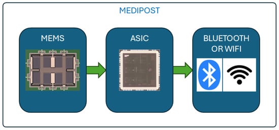
Figure 1.
Block diagram of the Medipost system.
While development of the device is still in progress, this article presents an analysis focused on one of the system’s key components—the MEMS accelerometer. For this purpose we use a model obtained from MEMS+ and simulate it in MATLAB v. R2024a Simulink. This analysis provides many information regarding the sensor’s operation.
In the following sections, the authors describe the idea of the MEMS accelerometer responsible for measuring acceleration. The simulation results of the MEMS and its interaction with the analog-to-digital converter (ADC) are discussed further in the text.
2. Materials and Methods
2.1. Accelerometer Sensor—Principle of Operation
In this section, the authors describe an acceleration sensor designed using MEMS technology. A three-axis sensor is designed by placed it on a single substrate. During the analysis, the authors focused on the performance of the single-axis sensor. The sensors operating in the X and Y planes have the same design. They are placed on a plane of silicon at 90 degrees to each other to measure the corresponding acceleration. Only the Z-axis sensor has a different design, as it operates out of plane. Some interesting information about this sensor can be found in [13].
Returning to X-axis sensors, their operation is based on differential mode. This means that the sensors contain two capacitors that operate in different ways. In the equilibrium state, both capacitances (top and bottom) have the same value. When acceleration in the X-axis occurs, the value of one capacitance increases and the other decreases (Figure 2). Therefore, the sensitivity of the sensor is better in comparison to the single capacitance.
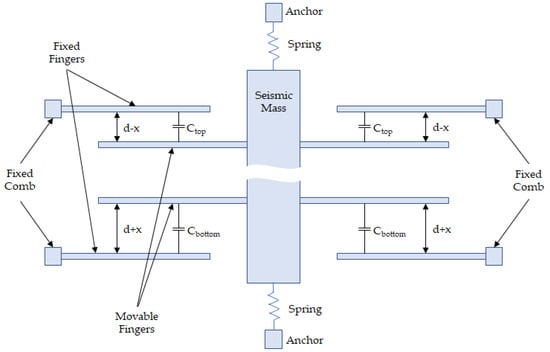
Figure 2.
The principle of operation of the capacitive accelerometer acting in the X- and Y-axes (not to scale) [13].
The sensor works in an open loop, where the response is proportional to the capacitance change (the movement of the seismic mass is proportional to the inertial force). This results in lower power consumption compared to closed-loop systems, where seismic mass must be kept in equilibrium.
2.2. Technology Used for Manufacturing the Sensor
To manufacture a MEMS sensor, it is necessary to use dedicated micromachining technology. In general, the two most commonly used technologies are surface micromachining and bulk micromachining [14,15,16]. All of them have some advantages and disadvantages. In surface micromachining, it is possible to produce sensors and other structures by depositing thin layers on the top surface of a wafer. Among the others, the sacrificial layers were deposited, which are eventually removed to obtain the released structures. This produces some inertial sensors or other structures with moving parts, such as micromotors [17,18]. The second technology is based on the removal of some of the silicon from the silicon substrate. Here, we may produce sensors that are suspended above the cavity. For example, we are able to produce pressure sensors, accelerometers, and other structures [19]. On the other hand, there also exists LIGA (ger. Lithographie, Galvanoformung, Abformung) technology, in which we can obtain small parts of microsystems using a molding process. We prepare a stamp mold using, i.e., polymethylmethacrylate (PMMA). After exposure it to X-rays, we remove the superfluous part of the material, and then deposit a layer of metal through an electroplating process. Finally, we obtain small fragments of the mechanical parts of microsystems such as tooth wheels, etc. [20].
In our case, we used X-FAB MEMS technology with a characteristic dimension of 1.0 m (XMB10 IC process) [21]. This technology allows us to design and manufacture inertial sensors with seismic mass and combs. We designed a triaxial accelerometer with movable seismic mass and fixed combs. However, manufacturing the X- and Y-axis accelerometer was not a very complicated process, compared to the Z-axis accelerometer which was a really huge challenge. We had to use two types of combs (normal and reduced-height) in this sensor to correctly detect the change in acceleration.
We chose to combine this technology with the application-specific integrated circuit (ASIC), which was also manufactured using X-FAB technology (180 nm IC process), Erfurt, Germany. We used two different technologies (one for the MEMS and one for the ASIC) that were provided by the same vendor so that they could be easily connected in a single package. More interesting information about this structure can be found at [13].
2.3. Sensor Model and Design
The design of the accelerometer was conducted in the Coventor MEMS+ v. 6.2 software [22]. It is a computer-aided design/electronic design automation (CAD/EDA) software that allows users to design a prototype using a library of sensor components. It is a very useful tool that allows us to quickly design a prototype sensor. It contains a library of components such as combs, beams, anchors, frames, etc. Using these components, it is possible to design a parametrized structure that can be simulated to find the optimal structure. All components were prepared using the technology mentioned above and were used in the model. Once designed, it was possible to simulate the sensor in the same software as well in DC and AC domains to find the optimal structure. Unfortunately, it is not possible to simulate the model in the time domain in MEMS+. We could simulate it in MATLAB Simulink [23], where we imported the sensor model from MEMS+. In order to speed up the simulation, the reduced-order model (ROM) was imported. This was a huge advantage as it directly influenced the simulation time. The design automation flow used in the project is shown in Figure 3. The model of the sensor designed in MEMS+ and the photo of it are presented in Figure 4.
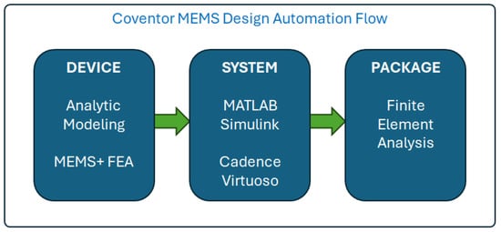
Figure 3.
Design flow of the MEMS and ASIC.
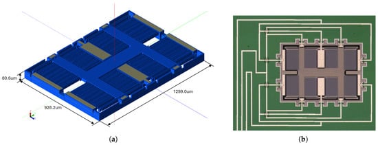
Figure 4.
MEMS accelerometer: (a) model in MEMS+ Innovator. (b) Photo under a microscope [13].
3. Results
The first simulation models were created in the MEMS+ software [22]. In this software we used a dedicated process design kit (PDK) provided by the technology’s vendor. It is a MEMS 1.0 m micromachining technology.
It was then possible to create a model that can be used in the CADENCE IC Design environment [24] to prepare the structure layout. This model was created using the Verilog-A language and could be simulated in an analog environment [24]. After successful simulation results, a layout mask was generated. The technology uses a small number of steps to produce the sensor. It is worth emphasizing that such simulations and layouts were performed, and finally the triaxial accelerometer was fabricated at the X-FAB silicon foundry [13].
Another method of designing and simulating the sensor was to develop a model that could be used in MATLAB Simulink [23]. This made it possible to simulate the sensor’s response to input signals in the time domain. Due to the complexity of the model, a ROM was used in MATLAB Simulink [25]. This is necessary to reduce the simulation time, as the simulations of the full-complexity model can take many hours or more. The reduced-order model was tuned to the first resonant frequency, which reduced the number of internal components required to reflect the behavior of the sensor in finite time. The results of the simulation of such a model are presented and discussed in this article.
The accelerometer model imported into the MATLAB Simulink environment (Figure 5) has three acceleration inputs for each axis. It also has three electrical inputs to which we applied electrical signals. For VEcapTop and VEcapBottom, we applied the square wave, but with the phase reversed. For VEcapMass we applied 2.5 volts. This was necessary to obtain optimal input conditions for the operation of the accelerometer. At the outputs of the model we have two capacitances (Ctop and Cbottom). Their variation is proportional to the input signal.
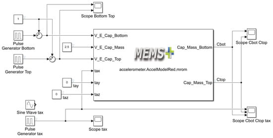
Figure 5.
Accelerometer model in MATLAB Simulink.
We present a complete analysis in the DC, AC and time domains further in this section. From the DC analysis we can obtain information about the change in capacitance as a function of acceleration. This dependence is linear as presented in Figure 6. As we are using a variant of two capacitances of the sensor’s construction (differential mode), we can see that for the acceleration in the range between g, the top capacitance value decreases whereas the bottom capacitance value increases.
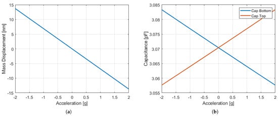
Figure 6.
Simulation results for g acceleration in MEMS+ for the X-axis accelerometer: (a) seismic mass displacement. (b) Capacitance change (Cbottom—blue line and Ctop—red line).
The next simulation was the modal analysis of the accelerometer. This was necessary to find the resonant frequency of the seismic mass of the sensor. The results of the simulations can be found in Table 1. From these results we may conclude that the correct operating range for the sensor is below the first resonant frequency, which is equal to kHz. The same information can be obtained from the AC analysis. The results of it are shown in Figure 7. We can see the resonance for the kHz frequency, which is very close to the modal analysis performed in MEMS+. This confirmed the limit of the operating range of the sensor to one kHz, which is below 6 kHz.

Table 1.
The eigenfrequencies of the X-axis accelerometer model.
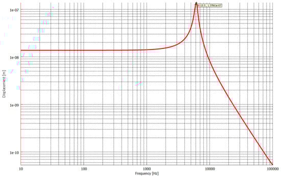
Figure 7.
Frequency response of the X-axis accelerometer in MEMS+.
The aforementioned simulations can also be performed in MEMS+; however, the transient simulation must be conducted in MATLAB Simulink. Further in this section we present the simulations for some different input signals applied to the inputs of the model.
At equilibrium, where all accelerations are zero, the two capacitances are also equal, and their value is pF. If we force the acceleration in the x-axis direction from 0 to 1 g, we see that the capacitance changes are equal to pF and pF (Figure 8). This is only a change of 10 fF for each capacitance. Importantly, we observe an oscillation in the sensor response of almost 2 ms. After this time, outputs of the sensor settle into equilibrium. These oscillations are related to the lower pressure inside the sensor, which is 800 Pa, meaning that it is very sensitive. In a real sensor, we have small differences in the top and bottom capacitance in the equilibrium state, which have to be trimmed by the ASIC. Only in this way can the achieved optimal state of the sensor for 0 g acceleration be achieved.
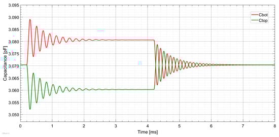
Figure 8.
Simulation results of the X-axis accelerometer for input acceleration equal to a pulse of 1 g in MATLAB Simulink. Capacitance change (Cbottom—red line and Ctop—green line).
The next simulation results show the response of the sensor to a sinusoidal input signal representing external acceleration. The amplitude of the signal was equal to g, and the frequency is equal to 100 Hz. As can be seen in Figure 9, the response of the sensor is very good. The output capacitance changes along with a sine wave with an amplitude of 40 fFp-p. A total of V has been applied to the seismic mass pin to polarize this part of the structure and eliminate the possibility of oscillations in the sensor response.
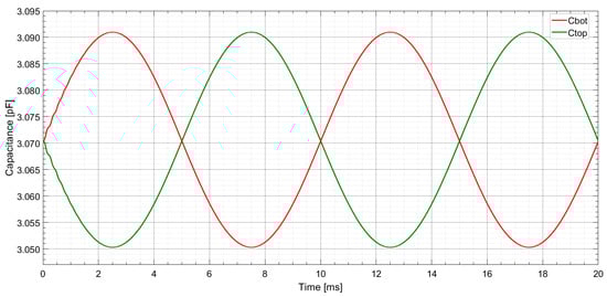
Figure 9.
Simulation results of the X-axis accelerometer for sinusoidal acceleration equal to an amplitude of 2 g and a frequency of 100 Hz in MATLAB Simulink. Capacitance change (Cbottom—red line and Ctop—green line).
To test the behavior of the accelerometer in the system, we added an electronic circuit whose main task is to convert the input signal to digital. We created two models in the Simulink system. The first one is a delta modulator, and the second one is the demodulator (Figure 10 and Figure 11).
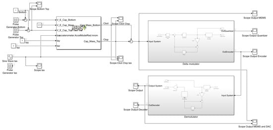
Figure 10.
Accelerometer model with a delta modulator and demodulator in MATLAB Simulink.
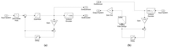
Figure 11.
Accelerometer with the processing part model in MATLAB Simulink: (a) delta modulator; (b) delta demodulator.
Figure 12 shows the simulation results of the MEMS accelerometer output and the reconstructed signal from the delta modulator. The input to the system is a sinusoidal acceleration signal with an amplitude of 2 g and a frequency of 80 Hz. The vertical axis represents capacitance in femtofarads and the horizontal axis represents time in milliseconds. The red curve labeled MEMS represents the actual output of the simulated MEMS accelerometer which responds to the applied acceleration by producing a changing capacitance signal. The green curve labeled DAC shows the output of the digital-to-analog conversion process after the signal has been quantized, processed, and reconstructed. At the beginning of the plot the DAC signal slightly lags and differs in amplitude compared to the MEMS output. This initial deviation is likely due to system startup effects or delay introduced by the delta converter and filtering stages. As time progresses the DAC output more closely follows the MEMS signal in both amplitude and phase. The overall trend shows that the system is capable of accurately reconstructing the original analog signal after processing through the delta modulator and demodulator stages with only minor transient mismatches. This indicates a high level of fidelity in the signal conversion process and confirms the effectiveness of the implemented simulation model in capturing the dynamic behavior of the sensor.
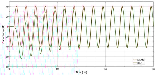
Figure 12.
Simulation results of the input acceleration equal to an amplitude of 2 g and a frequency of 80 Hz in MATLAB Simulink (MEMS accelerometer output (red line) and and digital-to-analog converter output (green line)).
Figure 13 shows the top-level Simulink model of an accelerometer system with a sigma-delta analog-to-digital converter. At the center is a MEMS accelerometer model labeled accelerometer.AccelModelRed.mrom which simulates the behavior of a capacitive sensor using pre-defined reduced-order models. The model receives excitation signals in the form of voltages applied to the bottom, top, and central sensing electrodes. These voltages come from a combination of constant values and pulse generators, simulating dynamic conditions or electrical excitation. A sine wave input labeled tax is used to simulate acceleration along the X-axis, which serves as the primary mechanical stimulus for the sensing system.
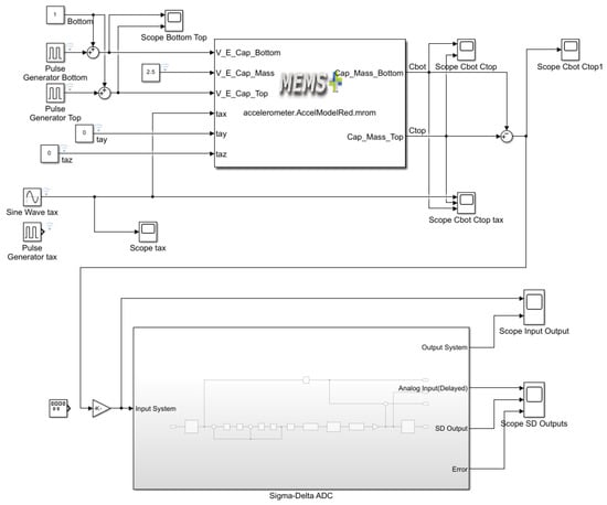
Figure 13.
Accelerometer model with the sigma-delta ADC in MATLAB Simulink.
The accelerometer outputs changing capacitances Ctop and Cbot, corresponding to the top and bottom sensing electrodes. These capacitances change depending on the displacement of the proof mass due to the acceleration applied. These two signals are visualized separately and then subtracted to create a differential capacitance signal that is more sensitive to motion and less affected by noise or common-mode disturbances. This differential capacitance signal is then fed into a subsystem representing the sigma-delta ADC, which is shown in detail in Figure 14. Inside this ADC block the analog signal is processed through modulation, quantization, filtering, and decimation stages to produce a digital output. The model also includes a path that delays the analog signal to align it with the digital output, allowing accurate calculation of the error between the original and reconstructed signals. Several scope blocks are used throughout the model to monitor important signals such as the input acceleration, individual capacitance values, the differential signal, and both the analog and digital outputs of the ADC. The complete system demonstrates a realistic simulation of a MEMS accelerometer signal chain from physical excitation through capacitive sensing to digital conversion and error analysis.
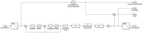
Figure 14.
Sigma-delta analog-to-digital converter model in MATLAB Simulink.
In Figure 15, we can see the input and output signals obtained from the sigma-delta ADC. The top plot shows the input capacitance signal over time. It is a smooth sinusoidal waveform ranging from nF to nF with a period of about 10 ms, representing an ideal analog signal. The middle plot shows the output from the sigma-delta converter, which attempts to reproduce the input signal in a quantized digital form. Although it follows the general shape of the input, the signal is visibly stepped or quantized, indicating limited resolution during digital conversion. The bottom plot represents the error, which is the difference between the input and output signals. The error signal fluctuates in a periodic and oscillatory manner, reaching peaks of about nF. The largest deviations appear during the steep slopes of the sine wave where the rate of change is highest. This behavior is typical of quantization noise and imperfections in the digital conversion process. In summary, the system reproduces the general behavior of the input signal but introduces quantization artifacts, resulting in small but noticeable errors, particularly during fast transitions. Despite this its performance appears acceptable and within expected limits for a sigma-delta-based system.
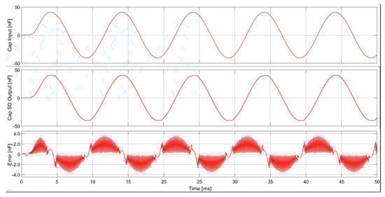
Figure 15.
Simulation results of the capacitance change as an input signal (top), quantized output capacitance change (middle), and signal error (bottom).
Figure 16 shows the input and output signals of the accelerometer connected to the sigma-delta ADC. The acceleration for this case was equal to 2 g in amplitude and a frequency equal to 80 Hz. The output signal is the same as the input but with a small delay. It is related to the usage of the input low-pass filter with the cut-off frequency equal to 400 Hz. It is possible to tune the output signal by using the last filter in the system. The usage of the second-order sigma-delta ADC allowed us to reduce the noise in the output signal because it is shifted to higher frequencies. This is the main advantage of using a sigma-delta ADC.
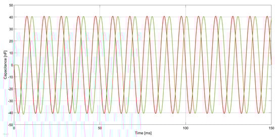
Figure 16.
Simulation results of the input acceleration equal to an amplitude of 2 g and a frequency of 80 Hz in MATLAB Simulink (MEMS accelerometer output (red line) and digital-to-analog converter output (green line)).
Based on the analysis, we determined the main parameters of our ADC. For the second-order sigma-delta converter, we obtained a signal-to-noise ratio (SNR) of dB. We calculated an effective number of bits (ENOB) of . Then, the total harmonic distortion (THD) is equal to dB. We chose this type of converter because of the compromise between its complexity and the obtained parameters. This was influenced, as mentioned earlier, by the goal of obtaining low power consumption of the circuit and a small size.
As a preliminary measurement of the sensor, a static analysis was performed. A MEMS accelerometer with an external readout circuit on a moving lever was mounted. This simple model reflects the patient. Then, static gravitational acceleration was measured. Measurements were taken at four angles (0, 30, 60, and 90 degrees). The results were converted to acceleration and are presented in Figure 17. They show that the MEMS accelerometer is very sensitive to external interference and needs to be connected with a dedicated ASIC in a single package. The current work focuses on dynamic measurements, which will be presented in future articles.
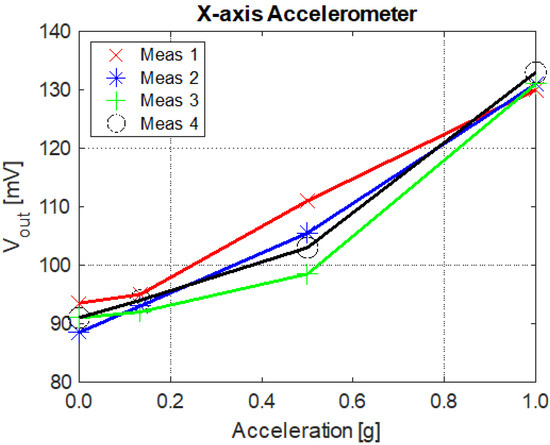
Figure 17.
The measured output voltage of the external readout circuits with the MEMS accelerometer as a function of acceleration. The measured device was positioned at four angles (0, 30, 60, and 90 degrees). The same measurements were repeated four times [13].
Finally, we compared our sensor with other accelerometers available on the market (Table 2). We can see that our structure has very good linearity. This is satisfactory when we talk about monitoring patients’ movement, where a small range of acceleration is required (about g). Note, that its size is comparable to other accelerometers. Its construction, based on the separate design of each axis sensor, reduces the sensitivity to acceleration in other directions. This is crucial when we consider the application our accelerometer to medical purposes.
Table 2.
Parameters of three-axis multiple-seismic-mass accelerometers.
4. Discussion
This article presents the analysis of the MEMS acceleration sensor, which constitutes the continuation of the analysis written in the article [13], which focused mainly on the static analysis of the sensor. We have analyzed the behavior of the sensor in the DC, AC, and time domains.
In the DC and AC domains, we obtained the static sensor behavior and its frequency response. It should be noted that the sensor used in the Medipost device will operate in the range of g. Therefore, the analysis presents the behavior of the sensor in this range of acceleration. The DC response of the sensor is linear in the mentioned range. The first eigenfrequency in the AC domain is also observed near kHz. This is sufficient to meet our requirements.
The time-domain analysis showed that the sensor was very sensitive to acceleration. The low pressure inside the sensor caused the seismic mass to oscillate with a time constant of 3 milliseconds. The size of the sensor gives a small total capacitance of pF with a sensitivity of about 10 fF/g according to MATLAB Simulink simulations. This requires a dedicated readout circuit to be connected to the sensor.
We tested the behavior of the sensor with the delta modulator and the sigma-delta ADC. In both cases the system works correctly. However, it is not so simple to setup proper simulation solver conditions for such a complex system. After many analyses we find the optimal simulation condition, which is the Simulink solver with a fixed number of steps.
The performed analysis showed that the acceleration sensor operates correctly for the small frequencies of the input signal. For the input signal we assumed that the signal is equal to g with a frequency of about 100 Hz. Such parameters are interesting for the Medipost device, which is used for patient movement monitoring. Such a device is connected to a smartphone with a data analysis system installed. In the future we will present further simulations and measurements results related to that sensor.
To summarize, we use a model generated in the MEMS+ software and analyze it in MATLAB Simulink. One of the important advantage of this approach is to design a scalable model with predefined components in the MEMS+ software. The design is faster in comparison to the standard approach with the usage of the finite element model (FEM) in ANSYS 15.0 [33] or COMSOL 5.2a Multiphysics [34] software. Another advantage is that in MEMS+, the PDK is presented with the design rules checked. These rules have to be met in the layout of the sensor, which is then sent to the silicon foundry for manufacturing. The link with another software such MATLAB or CADENCE 6.1.7 is also an advantage of the MEMS+ software. Despite many advantages, there are also some disadvantages. One of them is the lack of the time-domain analysis of the structure. We need to use external software to perform such an analysis. However, the complex analysis of the structure of the sensor has to be performed with, e.g., MATLAB Simulink, so that we can obtain in a short time the full analysis of our design.
5. Conclusions
This work presents an extended dynamic analysis of a MEMS capacitive accelerometer, complementing the static evaluation discussed in earlier studies. While the previous work focused primarily on static characteristics and the frequency response, this study explores the time-domain behavior, digital signal processing performance, and system integration with a sigma-delta analog-to-digital converter (ADC). The accelerometer model was developed using the MEMS+ software, which enabled rapid system-level modeling with built-in design rule checking (DRC) and parametric component libraries. The model was then imported into MATLAB Simulink, where full-system simulations—including mechanical excitation, capacitive sensing, and analog-to-digital conversion—were performed. DC and AC analyses confirmed that the sensor operates linearly within the g acceleration range, which matches the expected operational range for Medipost wearable devices. The first resonance frequency was observed at approximately kHz, indicating sufficient bandwidth for low-frequency physiological signal acquisition, such as human motion, gait, or posture. Time-domain simulations show that the sensor is highly responsive to applied acceleration, with a time constant of about 3 ms due to the low-pressure damping environment. The resulting signal exhibits relatively low capacitance variation (on the order of 10 fF/g), which requires highly sensitive and noise-resilient readout circuitry. To digitize the signal, a second-order sigma-delta ADC was designed in Simulink, as shown in Figure 14. The ADC was tested using synthetic acceleration signals ( g at 80 Hz and 100 Hz), which are representative of the target application domain. The modulator and decimator chain within the ADC effectively captured the analog input, and its digital output was validated against the original signal.
The use of MEMS+ and MATLAB Simulink enabled efficient, multi-domain modeling of a capacitive MEMS accelerometer with integrated signal processing. The simulations confirm that the sensor exhibits linear and stable behavior within its operational range and that the designed sigma-delta ADC can accurately digitize and reconstruct dynamic signals with high resolution and low noise. This modeling workflow offers several advantages over conventional FEM approaches, such as faster prototyping, a DRC-compliant design, and streamlined simulation integration with software environments like MATLAB. While MEMS+ lacks direct time-domain simulation capabilities, coupling it with Simulink allows full behavioral analysis, including signal fidelity and ADC performance. The analysis confirms that the proposed sensor–ADC system is well-suited for wearable applications involving human motion monitoring. Future work will involve validation against physical measurements and further optimization of the readout circuitry for ultra-low-power embedded systems.
Author Contributions
Conceptualization, M.S. and J.N.; methodology, M.S.; validation, M.S. and J.N.; formal analysis, M.S.; investigation, M.S.; writing—original draft preparation, M.S.; writing—review and editing, M.S. and J.N.; visualization, M.S. All authors have read and agreed to the published version of the manuscript.
Funding
The results presented in the paper are supported by the project STRATEGMED2/266299/19NCBR/2016, which is funded by The National Centre for Research and Development in Poland.
Institutional Review Board Statement
Not applicable.
Informed Consent Statement
Not applicable.
Data Availability Statement
The original contributions presented in this study are included in the article. Further inquiries can be directed to the corresponding author.
Acknowledgments
The authors would like to express their deep gratitude to the late Andrzej Napieralski from Lodz University of Technology for their support and deep commitment during the implementation of the STRATEGMED project.
Conflicts of Interest
The authors declare no conflicts of interest.
References
- Sundmaeker, H.; Guillemin, P.; Friess, P.; Woelfflé, S. Vision and challenges for realising the Internet of Things. Clust. Eur. Res. Proj. Internet Things Eur. Commision 2010, 3, 34–36. [Google Scholar]
- Napieralski, A.; Napieralska, M.; Szermer, M.; Maj, C. The evolution of MEMS and modelling methodologies. COMPEL-Int. J. Comput. Math. Electr. Electron. Eng. 2012, 31, 1458–1469. [Google Scholar]
- Bryzek, J. MEMS Tornado to Challenge Next Generation Packaging. Addit. Conf. (Device Packag. HiTEC HiTEN CICMT) 2012, 2012, 000417–000456. [Google Scholar] [CrossRef]
- Li, W.; Lu, W.; Sha, X.; Xing, H.; Lou, J.; Sun, H.; Zhao, Y. Wearable Gait Recognition Systems Based on MEMS Pressure and Inertial Sensors: A Review. IEEE Sens. J. 2022, 22, 1092–1104. [Google Scholar] [CrossRef]
- Jiang, X.; Shokouhmand, A.; Ebadi, N.; Ayazi, F. Fingertip Plethysmography Using A Sensitive Wafer-Level-Packaged Capacitive MEMS Strain Sensor. In Proceedings of the 2024 IEEE 37th International Conference on Micro Electro Mechanical Systems (MEMS), Austin, TX, USA, 21–25 January 2024; pp. 348–351. [Google Scholar] [CrossRef]
- Huang, X.; Xue, Y.; Ren, S.; Wang, F. Sensor-Based Wearable Systems for Monitoring Human Motion and Posture: A Review. Sensors 2023, 23, 9047. [Google Scholar] [CrossRef] [PubMed]
- Xu, T.; Wang, J.; Yu, J.; Fu, Y.; Bai, R. Wearable Human Attitude Visualization Tracking System Based on MEMS Inertial Sensors. In Proceedings of the 2025 6th International Conference on Electrical, Electronic Information and Communication Engineering (EEICE), Shenzhen, China, 18–20 April 2025; pp. 1467–1472. [Google Scholar] [CrossRef]
- Alessandrini, M.; Micarelli, A.; Viziano, A.; Pavone, I.; Costantini, G.; Casali, D.; Paolizzo, F.; Saggio, G. Body-worn triaxial accelerometer coherence and reliability related to static posturography in unilateral vestibular failure. J. Vestib. Res. 2017, 37, 231–236. [Google Scholar] [CrossRef] [PubMed]
- Kim, S.C.; Kim, M.J.; Kim, N.; Hwang, J.H.; Han, G.C. Ambulatory balance monitoring using a wireless attachable three-axis accelerometer. J. Vestib. Res. Equilib. Orientat. 2013, 23, 217–225. [Google Scholar] [CrossRef] [PubMed]
- Tylman, W.; Kotas, R.; Kamiński, M.; Marciniak, P.; Woźniak, S.; Napieralski, J.; Sakowicz, B.; Janc, M.; Józefowicz-Korczyńska, M.; Zamysłowska-Szmytke, E. Fully Automatic Fall Risk Assessment Based on a Fast Mobility Test. Sensors 2021, 21, 1338. [Google Scholar] [CrossRef] [PubMed]
- Jankowski, M.; Szermer, M.; Amrozik, P. Concept of an Electronic Device Dedicated to Imbalance Disorders Monitoring. In Proceedings of the 2019 IEEE 15th International Conference on the Experience of Designing and Application of CAD Systems (CADSM), Polyana, Ukraine, 26 February–2 March 2019; pp. 23–26. [Google Scholar] [CrossRef]
- Kotas, R.; Janc, M.; Kamiński, M.; Marciniak, P.; Zamysłowska-Szmytke, E.; Tylman, W. Evaluation of Agreement Between Static Posturography Methods Employing Tensometers and Inertial Sensors. IEEE Access 2019, 7, 164120–164126. [Google Scholar] [CrossRef]
- Szermer, M.; Zając, P.; Amrozik, P.; Maj, C.; Jankowski, M.; Jabłoński, G.; Kiełbik, R.; Nazdrowicz, J.; Napieralska, M.; Sakowicz, B. A Capacitive 3-Axis MEMS Accelerometer for Medipost: A Portable System Dedicated to Monitoring Imbalance Disorders. Sensors 2021, 21, 3564. [Google Scholar] [CrossRef] [PubMed]
- Maluf, N.; Williams, K. Introduction to Miroelectromechanical Systems Engineering, 2nd ed.; Artech: Singapore, 2004. [Google Scholar]
- Zhu, X. Post-CMOS Micromachining of Surface and Bulk Structures. Ph.D. Thesis, Carnegie Mellon University, Pittsburgh, PA, USA, 2002. [Google Scholar]
- French, P.J.; Sarro, P.M. Surface versus bulk micromachining: The contest for suitable applications. J. Micromech. Microeng. 1998, 8, 45. [Google Scholar] [CrossRef]
- Leinenbach, C.; Kattelus, H.; Knechtel, R. Chapter 19—Surface micromachining. In Handbook of Silicon Based MEMS Materials and Technologies, 3rd ed.; Tilli, M., Paulasto-Krockel, M., Petzold, M., Theuss, H., Motooka, T., Lindroos, V., Eds.; Micro and Nano Technologies; Elsevier: Amsterdam, The Netherlands, 2010; pp. 503–517. [Google Scholar] [CrossRef]
- Esteve, D.; Alderman, J.; Cane, C.; Ciurtois, B.; Glesner, M.; Napieralski, A.; Rencz, M.; Samitier, J.; Troccaz, J.; Cinquin, P.; et al. Basic Research for Microsystems Integration; Cepadues-Editions: Toulouse, France, 1997. [Google Scholar]
- Rao, A.V.N.; Pal, P.; Pandey, A.K.; Menon, P.K.; Tanaka, H.; Sato, K. High Speed Silicon Wet Bulk Micromachining of Si111 in KOH Based Solution. In Proceedings of the 2020 Symposium on Design, Test, Integration and Packaging of MEMS and MOEMS (DTIP), Lyon, France, 15–26 June 2020; pp. 1–5. [Google Scholar] [CrossRef]
- Menz, W. Liga And Related Technologies For Industrial Application. In Proceedings of the International Solid-State Sensors and Actuators Conference—TRANSDUCERS’95, Stockholm, Sweden, 25–29 June 1995; Volume 1, pp. 552–555. [Google Scholar] [CrossRef]
- X-FAB Prototyping Support. 2025. Available online: https://www.xfab.com/manufacturing/prototyping (accessed on 18 March 2025).
- A Lam Research, C. Introduction to MEMS+. 2025. Available online: https://www.coventor.com/courses/introduction-to-mems/ (accessed on 18 March 2025).
- MathWorks. MATLAB Simulink. 2025. Available online: https://www.mathworks.com/products/simulink.html (accessed on 18 March 2025).
- CADENCE IC Design Suite. 2025. Available online: https://www.cadence.com/en_US/home/tools/custom-ic-analog-rf-design.html (accessed on 18 March 2025).
- MathWorks. MATLAB Simulink—Reduced Order Modeling. 2025. Available online: https://www.mathworks.com/discovery/reduced-order-modeling.html (accessed on 18 March 2025).
- Lemkin, M.; Boser, B. A three-axis micromachined accelerometer with a CMOS position-sense interface and digital offset-trim electronics. IEEE J. Solid-State Circuits 1999, 34, 456–468. [Google Scholar] [CrossRef]
- Matsumoto, Y.; Nishimura, M.; Matsuura, M.; Ishida, M. Three-axis SOI capacitive accelerometer with PLL C-V converter. Sens. Actuators A Phys. 1999, 75, 77–85. [Google Scholar] [CrossRef]
- Chae, J.; Kulah, H.; Najafi, K. A monolithic three-axis micro-g micromachined silicon capacitive accelerometer. J. Microelectromech. Syst. 2005, 14, 235–242. [Google Scholar] [CrossRef]
- InvenSense. MPU-6000 and MPU-6050 Product Specification Revision 3.3. 2012. Available online: https://invensense.tdk.com/wp-content/uploads/2015/02/MPU-6000-Datasheet1.pdf (accessed on 13 May 2025).
- Liu, Y.; Tsai, M.; Li, S.; Fang, W. A Fully-Differential, Multiplex-Sensing Interface Circuit Monolithically Integrated with Tri-Axis Pure Oxide Capacitive CMOS-MEMS Accelerometers. In Proceedings of the 17th International Conference on Solid-State Sensors, Actuators and Microsystems, Barcelona, Spain, 16–20 June 2013. [Google Scholar]
- Tez, S.; Aykutlu, U.; Torunbalci, M.; Akin, T. A Bulk-Micromachined Three-Axis Capacitive MEMS Accelerometer on a Single Die. J. Microelectromech. Syst. 2015, 24, 1264–1274. [Google Scholar] [CrossRef]
- Devices, A. ADXL345 Data Sheet. 2022. Available online: https://www.analog.com/media/en/technical-documentation/data-sheets/adxl345.pdf (accessed on 13 May 2025).
- ANSYS, a CAD Software Suite. 2025. Available online: https://www.ansys.com/ (accessed on 9 June 2025).
- COMSOL Multiphysics. 2025. Available online: https://www.comsol.com/ (accessed on 9 June 2025).
Disclaimer/Publisher’s Note: The statements, opinions and data contained in all publications are solely those of the individual author(s) and contributor(s) and not of MDPI and/or the editor(s). MDPI and/or the editor(s) disclaim responsibility for any injury to people or property resulting from any ideas, methods, instructions or products referred to in the content. |
© 2025 by the authors. Licensee MDPI, Basel, Switzerland. This article is an open access article distributed under the terms and conditions of the Creative Commons Attribution (CC BY) license (https://creativecommons.org/licenses/by/4.0/).