1. Introduction
The fifth generation (5G) of mobile communication offers three primary categories of services: enhanced mobile broadband (eMBB), massive machine-type communications (mMTCs), and ultra-reliable low-latency communications (URLLCs). Mobile Network Operators (MNOs) typically deploy these services through public 5G networks, utilizing Quality-of-Service (QoS) and network-slicing mechanisms to differentiate and manage them. Given the diverse requirements of various use cases, such as secure communication and full control over network infrastructure, private 5G [
1,
2], also referred to as non-public networks by the 3rd Generation Partnership Project (3GPP), has emerged as a promising solution. It allows companies and institutions to independently customize, deploy, and manage their own infrastructure to meet specific demands. Despite these benefits, the high costs of building and operating such networks remain a major concern. Consequently, reducing deployment and operational expenses has attracted significant attention in recent studies [
3,
4,
5].
In private 5G architectures, edge computing is a critical component. It enables the deployment of local User Plane Function (UPF) and applications closer to end devices, thereby reducing latency, enhancing network performance, improving data security, and facilitating real-time data processing [
6]. Hence, the future is expected to see an increasing deployment of small edge computing sites to extend coverage, enhance network responsiveness, and improve the scalability and performance of edge-enabled applications [
7]. Such an approach also enables flexible deployment of edge services across multiple sites, allowing requests to be dynamically routed to the most appropriate location based on demand and context. Despite its many advantages, edge computing poses several critical challenges. In this work, we focus on two key aspects of it in a private 5G network.
The first challenge lies in the resource constraints of edge computing environments, which often have a limited Central Processing Unit (CPU), memory, and storage capacity. To optimize cost and fully utilize available resources, edge applications and UPF are typically deployed on the same edge server using virtualization technologies [
5], particularly containers. Compared to traditional virtual machines, containers not only reduce overhead and improve resource utilization but also enable faster application startup times, enhancing responsiveness and deployment flexibility. Additionally, using multiple edge computing sites is essential to increase overall resource availability; however, managing workloads across multiple distributed edge sites introduces complexity. Therefore, efficient workload orchestration mechanisms across multiple edge sites are required to manage deployment efficiently.
The second challenge comes from the inherently unreliable nature of edge computing environments [
8,
9], which are susceptible to factors such as power outages, hardware or software failures, and operating system updates. These issues can lead to service interruptions and failed request processing. To mitigate these risks, highly available and resilient mechanisms must be implemented for both applications and local UPFs. For the application services, a common approach is to deploy multiple replicas across different edge sites, allowing requests to be redirected to active instances elsewhere. For the UPF, redundancy methods [
10,
11], such as 1:1 or N:M configurations, are widely used in traditional core networks by launching standby UPF instances. This setup enables quick traffic redirection in the case of failure, minimizing service disruption. However, these redundancy strategies can be inefficient and waste resources, as backup UPF instances often remain idle and infrequently used, leading to resource underutilization and reduced scalability of co-located applications on the same edge server [
12].
To address these challenges, in this paper, we propose a novel design and implementation of failover mechanisms for container-based UPF deployed across clusters: for example, distributed edge sites. Our approach significantly improves resource efficiency by eliminating the need for idle backup instances while ensuring high resilience in resource-constrained edge environments. Moreover, the solution enables seamless UPF failover across clusters, minimizing service disruption and supporting continuous operation. Our main contributions can be summarized as follows:
Failover Container-Based UPF Within a Cluster: A mechanism that enables the recovery of a containerized UPF either on a different node or on the original node within the cluster, depending on conditions such as resource availability.
Failover Container-Based UPF Across Multiple Clusters: A mechanism that supports the recovery of a containerized UPF across different clusters, even when network configurations and other environmental conditions differ.
We implement the proposed mechanisms on a testbed and conduct a comprehensive evaluation, comparing their performance with state-of-the-art approaches from the literature.
Further details are presented throughout this paper, which is organized as follows:
Section 2 provides background information and reviews related work about the state-of-the-art of failover UPFs.
Section 3 introduces our proposed design and architecture for enhancing the resilience of container-based UPF.
Section 4 describes the testbed and implementation details.
Section 5 presents the evaluation results and discussion, and
Section 6 concludes this paper with key findings and future directions.
2. Background and Related Works
2.1. Private 5G Network
As its name suggests, a private 5G network is a dedicated internal wireless network that utilizes similar network components as public 5G networks but is deployed to operate independently or in partial coordination with public cellular infrastructure [
13]. Typically implemented by enterprises or organizations, private 5G is designed to meet stringent service requirements in terms of reliability, low latency, dynamic resource reconfiguration, and rapid redeployment [
2].
According to [
1], in the 3GPP Release 16 standard, private 5G networks are generally classified into two main deployment models: standalone deployment and integrated public network deployment. In the standalone model, the private 5G network is fully isolated and operates independently of any public network, offering maximum control and customization. In contrast, in the integrated public network model, the private 5G system shares resources with the public network mainly through the network slicing mechanism [
14], reducing deployment costs, but it may have less customization, control, and security. Regardless of the deployment approach, edge computing plays a pivotal role in private 5G, enabling ultra-low-latency and high-bandwidth connectivity between devices and applications [
15,
16].
By positioning computation resources closer to the end devices, such as in multi-access edge computing (MEC) sites near Radio Access Network (RAN) base stations or housing compounds, retail centers, or even at the edge of the mobile operator’s core network [
17], data processing can occur with fewer network hops and also increased reliability. Each edge node typically includes a local UPF, which allows user devices to directly connect to applications running on edge servers, thereby enhancing performance and supporting critical real-time use cases.
2.2. Migrate a Running Application
Edge computing can bring many benefits to users, but it is still hampered by reliability concerns. One of the main limitations is the constrained computational resources at edge nodes [
18]. When these resources are fully utilized or insufficient for incoming requests, processing delays increase, and the quality of service may degrade. Additionally, the physical infrastructure of edge environments is often less stable and more vulnerable to external factors. Power outages, caused by extreme weather events, climate change [
9], hardware failures, or software malfunctions, can lead to complete shutdowns of edge sites. In such cases, all applications running on the affected edge node may be disrupted. As a result, the ability to migrate applications from one edge node to another is not just beneficial but a necessary requirement to ensure service continuity and reliability.
Checkpoint/Restore In Userspace (CRIU) [
19] is a powerful tool that enables application migration at the system level. As its name suggests, CRIU allows a running process, or even a group of processes, to be checkpointed from userspace into a set of image files stored on disk. These checkpointed images can later be restored either on the same machine or on a different host, effectively resuming execution from the exact state at the time of checkpointing. By leveraging CRIU, systems can significantly reduce downtime and eliminate the need to restart applications from scratch. These reasons make CRIU an important tool for live migrating container-based applications in edge computing environments, where ensuring uninterrupted service is essential due to resource constraints and the risk of system unreliability.
2.3. User-Plane Function 5G
Within the 5G Core Network, a UPF is a critical data-plane component designed to handle user traffic with high efficiency, enabling core functions such as traffic routing, policy enforcement, and real-time data forwarding across multiple network interfaces. Architecturally, the UPF consists of two primary sub-modules: the control sub-module and the forwarding sub-module [
20].
The control sub-module operates based on instructions received from the Session Management Function (SMF) via the N4 interface and is responsible for orchestrating the behavior of the UPF by handling tasks such as node status reporting, Packet Forwarding Control Protocol (PFCP) message processing, and session management. In contrast, the forwarding sub-module is responsible for the real-time processing of user-plane traffic and related data, particularly at the N3, N6, and N9 interfaces. Its responsibilities include GPRS Tunneling Protocol–User Plane (GTP-U) data analysis and encapsulation for the N3 interface, maintaining GPRS Tunneling Protocol (GTP) channels, and managing forwarding forms with fast indexing mechanisms. Additionally, it has essential routing and packet-forwarding capabilities while enforcing various policy rules, such as the Packet Detection Rule (PDR), Forwarding Action Rule (FAR), QoS Enforcement Rule (QER), and Usage Reporting Rule (URR), to handle traffic behaviors and measurement reporting.
In private 5G deployments, edge computing environments often operate under resource constraints. To optimize cost-efficiency and resources, the UPF is typically deployed alongside applications on the same edge server, utilizing container-based virtualization technologies [
5]. Furthermore, a container-based UPF not only enables deployment on commercial off-the-shelf (COTS) hardware but also inherits the key advantages of cloud-native designs, including dynamic scaling, rapid deployment, and improved operational efficiency.
2.4. Related Works
Ensuring high availability and reliability is paramount in 5G UPF deployments. A common mechanism to achieve this is redundancy, typically implemented via active-standby configurations. These can manifest as 1:1 UPF redundancy, where each active UPF is paired with a dedicated standby instance, or N:M configurations, where a shared pool of N standby UPFs supports M active UPFs. The choice between these configurations is generally driven by Service-Level Agreements (SLAs) and the criticality of the services being supported: for example, 1:1 redundancy is often used for mission-critical use cases such as the Internet Protocol Multimedia Subsystem (IMS) or emergency calls, while N:M redundancy is more suitable for less critical data and internet services.
In a 1:1 setup [
10,
21,
22], the standby UPF can assume the active role immediately upon detecting a failure due to hardware faults, Operating System (OS) upgrades [
23], or other disruptive events [
9]. By leveraging pre-allocated session contexts, this mechanism ensures seamless user-plane continuity. However, dedicating one standby per active UPF leads to significant resource overhead, as these standby instances remain idle for long periods. On the other hand, N:M UPF redundancy [
11] can significantly reduce the deployment cost compared to a 1:1 setup by allowing multiple active UPFs to share a smaller pool of standby UPFs. Even so, these standby instances must still be provisioned and maintained, consuming capacity even when not in use, and failover times may be slightly longer due to the need to restore session states.
In addition, several techniques have been proposed to accelerate fault detection and reduce restoration times for redundancy approaches. For example, leveraging networking protocols such as GTP echo request/response from gnodeB (gNB), packet duplication [
24], or utilizing failure detection by upstream N6 routers can provide rapid identification of UPF failures. However, from a broader perspective, where cost-effectiveness and resource optimization are key considerations, especially in resource-constrained edge computing environments, the redundancy-based approach requires maintaining standby backup instances, which wastes capacity since these instances remain idle most of the time, ultimately conflicting with the primary objective of minimizing overhead at the edge.
Recognizing the inefficiencies of pre-provisioned standby resources, recent work has explored dynamic and on-demand UPF deployment strategies. Leiter et al. [
25] utilize the Open Network Automation Platform (ONAP), an orchestrator, to automate failover in container-based UPF deployments. Upon detecting a failure, the orchestrator dynamically deploys a new UPF instance, eliminating the need for pre-provisioned backups, but the results show a significant delay in achieving the ready container state due to setting up network configurations for the new instance. Tsourdinis et al. [
26] focus on accelerating the restoration process itself and investigate the use of CRIU to facilitate faster UPF restoration. However, the authors acknowledge the challenges inherent in the stateful nature of UPF applications. Therefore, their solution involves running UPF containers inside Virtual Machines (VMs) managed by KubeVirt and using live VM migration to transfer the UPF to a healthy host. While this technique offers potential benefits, the complexity of migrating entire VMs and the requirement for robust network infrastructure during the migration process limit its effectiveness, especially in edge computing scenarios.
In summary, ensuring high availability and resiliency for containerized UPF in edge computing environments, without relying on pre-provisioned backup instances and while enabling rapid recovery, remains an open research challenge. To address this need, in this paper, we propose a novel solution that combines advanced technologies to achieve both fast UPF recovery and resource efficiency by avoiding redundant instances. A detailed explanation of our design architecture is presented in the following section.
3. Design Architecture
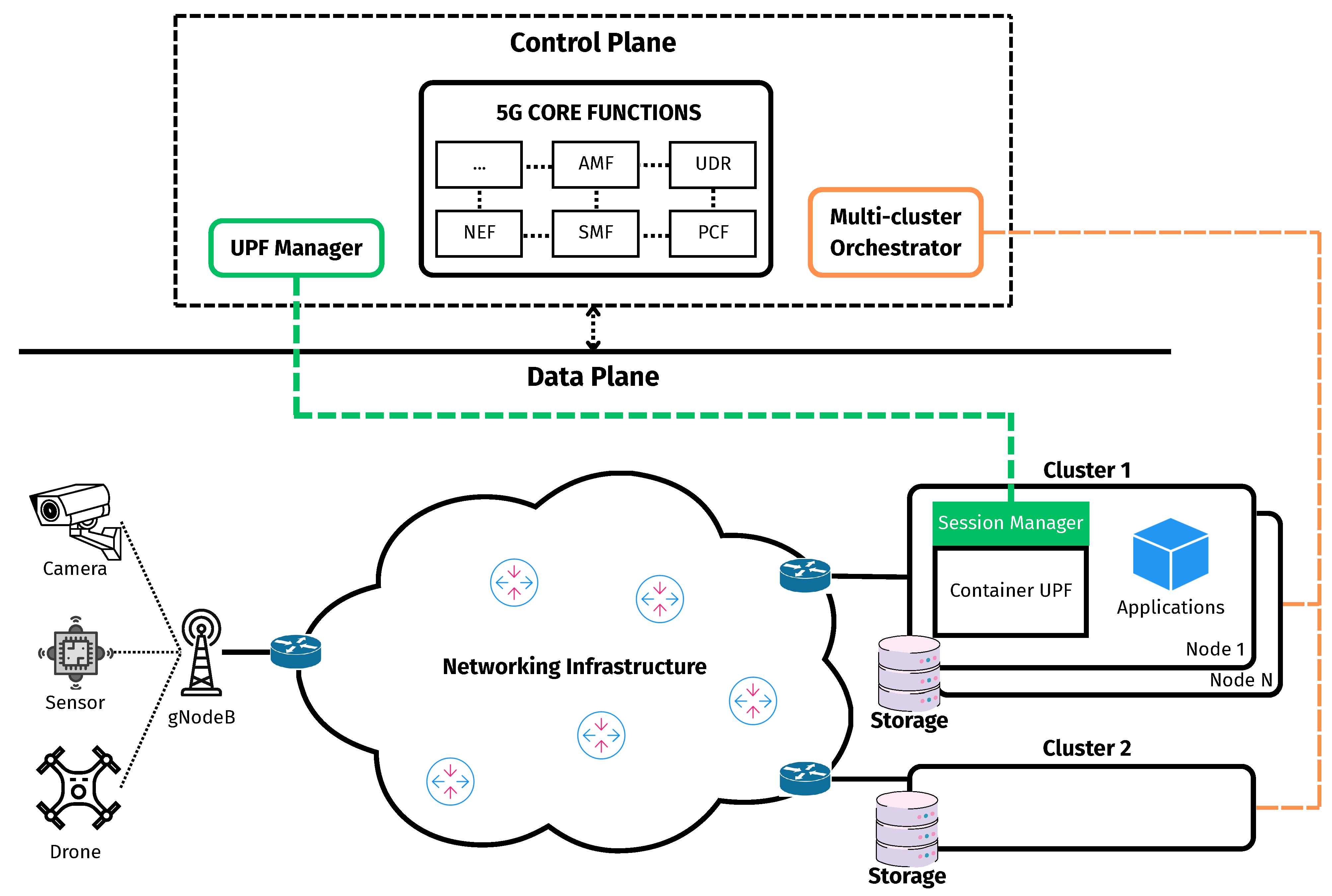
In this section, we present our proposed design architecture specifically for a failover container-based UPFs operating within a cluster, which also hosts other containerized application components. In this work, a cluster is defined as a set of one or more interconnected machines, either physical or virtual, configured to operate under a unified system. At least one node assumes the role of a master, while others, if present, serve as workers. In the case of a single-node cluster, that node may fulfill both roles. These machines must share the same networking setup and be capable of direct communication. The overall design architecture is illustrated in
Figure 1. The architecture comprises two distinct planes: a control plane and a data plane.. The control plane is composed of three main components responsible for centralized management and orchestration: the UPF Manager, the Multi-cluster Orchestrator, and the 5G core network control functions. In contrast, the data plane comprises the networking infrastructure, gNB, and other access network components, along with a set of clusters where UPF containers are deployed and operated to handle user data traffic in real time.
At the heart of the system’s operational oversight lies the control plane, overseeing configuration, monitoring, and failover container-based UPFs. It comprises the following:
Fifth-Generation Core Functions: Represent the suite of control-plane network functions, such as the AMF (Access and Mobility Management Function), SMF, UDR (Unified Data Repository), and PCF (Policy Control Function), which are responsible for session management, user data storage and retrieval, policy enforcement, network slicing, and other essential capabilities within the 5G Core Network.
Multi-cluster Orchestrator: Responsible for the management and monitoring of all clusters in the data plane, including handling the life-cycle management of containers, such as deployment, update, and deletion, and continuously monitoring the health status of clusters, individual nodes, and container instances across the infrastructure.
UPF Manager: Acts as the primary entity responsible for overseeing the failover process of container-based UPFs. It monitors the status of UPF containers by retrieving information from the Multi-cluster Orchestrator, while simultaneously maintaining direct connections with all UPF instances to receive real-time status reports. This dual approach enhances the accuracy and reliability of status detection. Additionally, the UPF Manager interacts with the 5G Core Network by communicating with 5G Core Functions either directly as a trusted Application Function (AF) or indirectly through the Network Exposure Function (NEF) when operating as a non-trusted AF. It also maintains a comprehensive backup repository of session-related information for all UPFs, including PDRs, FARs, and other relevant parameters.
On the data plane, where edge clusters host UPF instances, each UPF is equipped with a Session Manager component, which may be integrated within the UPF itself or deployed as a co-located auxiliary process. This component establishes a direct connection with the UPF Manager and continuously monitors the real-time state of the UPF, including all active sessions, PDRs, FARs, and other relevant parameters. Any changes in session-related data are promptly synchronized with the UPF Manager to ensure consistency.
Any changes in session-related data are promptly synchronized with the UPF Manager to ensure consistency. In addition to session monitoring, the Session Manager also tracks the PFCP associations maintained by the UPF. After PFCP association procedures such as setup, update, or release have been successfully completed, the Session Manager notifies the UPF Manager, which then initiates a checkpoint operation for the corresponding UPF container. This mechanism ensures that, in the event of a failure and the restoration of the UPF container, PFCP heartbeat procedures can resume seamlessly. To enable this, appropriate configurations must be in place to allow the UPF and the corresponding SMF to continue the previously established heartbeat procedure after recovery.
Each cluster is equipped with its own dedicated private storage, which is accessible only by the nodes within that cluster. The storage serves as a persistent repository for the checkpointed state data of UPF containers, written after a successful checkpoint operation. By keeping the state data local and access-restricted, the system achieves both improved security and faster recovery times.
The connection between each RAN and its associated compute cluster is established via the underlying networking infrastructure. Within a given cluster, all nodes share a unified internal network configuration, which may differ from that of other clusters. Moreover, to operate correctly, a UPF must be assigned multiple IP interfaces, such as N3, N4, N6, and N9. When a UPF container is restored from a checkpoint, it inherits the network settings associated with these interfaces. Consequently, the recovery process must ensure that the restored container can reconfigure its networking environment appropriately. Given these requirements, our design introduces two distinct failover mechanisms: (i) failover of a UPF container within the same cluster and (ii) failover across different clusters. Both failover mechanisms are handled by the UPF Manager.
3.1. Failover Container-Based UPF Within a Cluster
In the clustered environment defined earlier, where machines are interconnected and operate under a shared networking configuration, application workloads such as containerized services can be flexibly deployed and migrated across nodes. This capability allows the system to maintain service availability by relocating workloads to healthy nodes in response to failures. Therefore, in this section, we propose a restoration mechanism that ensures the recovery of a UPF container within the same cluster. Depending on the type of failure and the availability of resources, the UPF instance may be recovered either on a different node, for example, when the originally assigned node encounters an issue and becomes unavailable, or reinstated on the same one, such as in cases where it remains operational and resources are sufficient, and the issue may be related to the UPF itself. The detailed procedure is formalized in Algorithm 1.
Upon detecting a failure event, the UPF Manager identifies the affected UPF instance, along with the node and the cluster where the instance was previously operating. It then interacts with the Multi-cluster Orchestration component to assess the health status of the corresponding cluster and node, and it selects an appropriate node within that cluster to perform the restoration. Once a target node is selected, the UPF Manager verifies whether the checkpoint data of the affected UPF is already available on the selected node. If not, it instructs the node to retrieve the checkpoint data from a designated private storage system. After the checkpoint data is prepared, the UPF Manager backs up the networking configuration of the failed UPF container (e.g., N3, N4, N6, N9) and proceeds to remove the faulty container from the cluster. Finally, it restores the UPF container on the selected node by starting a new container with the checkpointed data and reattaches the saved networking configuration using container networking mechanisms such as the Container Network Interface (CNI).
| Algorithm 1 Failover container-based UPF within a cluster |
- 1:
function Main() - 2:
GetUPFInfo() - 3:
GetNodeAndClusterInfo() - 4:
if not IsNodeAvailable(, ) then - 5:
FindAppropriateNodeInCluster() - 6:
end if - 7:
RestoreUPF(, ) - 8:
ReattachInterfaces() - 9:
RestoreState() - 10:
end function
|
|
- 11:
function RestoreUPF(, ) - 12:
if not IsCheckpointImagePresent(, ) then - 13:
PullCheckpointImageFromPrivateStorage() - 14:
end if - 15:
BackupConfigContainer() - 16:
RemoveContainer() - 17:
InstantiateFromCheckpoint(, ) - 18:
return restoredUPF - 19:
end function
|
|
- 20:
function RestoreState() - 21:
while not IsConnectedToUPFManager() do - 22:
/* waiting for connection */ - 23:
end while - 24:
ReinstallSessionData() - 25:
end function
|
Once the UPF container has been restored and its original interface addresses reattached, communication between the Session Manager and UPF Manager is re-established. Upon confirmation of the renewed connection, the UPF Manager transfers the previously backed-up session-related data, including PDRs, FARs, and other parameters, and instructs the Session Manager to reinstall the corresponding state into the restored UPF. This restoration process is performed entirely between the UPF Manager and the UPF itself, without requiring any involvement from 5G control network functions. As a result, the restored UPF is able to continue its operation without initiating Protocol Data Unit (PDU) session re-establishment procedures or repeating PFCP association procedures with the SMF, making the restoration completely transparent to the UE.
3.2. Failover Container-Based UPF Across Multiple Clusters
In a multi-cluster environment, each cluster has different networking configurations. This makes it infeasible to apply the failover procedure described in Algorithm 1, because restoring a checkpointed UPF container requires the same networking interface configuration that existed at the time of checkpointing. When the checkpoint is created on a node in one cluster and restored on a node in another, this requirement cannot be guaranteed due to the heterogeneity of network configurations across clusters. To overcome this limitation, we propose a multi-cluster UPF failover mechanism, as described in Algorithm 2.
Upon detecting a failure event affecting a UPF instance and determining that the cluster hosting the instance has become unavailable, the UPF Manager examines the UPF’s associated policy to check whether a predefined target cluster for failover has been specified. If it exists, the failover proceeds accordingly. Otherwise, the UPF Manager interacts with the multi-cluster orchestrator to select a suitable target cluster, potentially favoring clusters already hosting the same application workload as the one originally served by the failed UPF. Once a target cluster is selected, the UPF Manager obtains the configuration of the selected cluster and initiates the deployment of a new UPF container through the multi-cluster orchestrator. The new UPF is provisioned with networking interfaces that match the destination cluster’s environment, and its operational configuration is replicated from the failed UPF. Once the new UPF container is instantiated, the UPF Manager coordinates with 5G core network functions to instruct the SMF to establish a PFCP association with the new UPF instance and to transfer all UE session contexts previously managed by the failed UPF to the new one. After the session transfer is completed, the UPF Manager proceeds to release the PFCP association with the affected UPF and remove its container from the system. This coordination may involve communication via the PCF if the UPF Manager operates as a trusted AF, or via the NEF in the case of a non-trusted AF.
| Algorithm 2 Failover container-based UPF across multiple clusters |
- 1:
function Main() - 2:
GetUPFInfo() - 3:
GetUPFPolicyFailover() - 4:
if then - 5:
GetPredefinedCluster() - 6:
else - 7:
SelectTargetCluster() - 8:
end if - 9:
GetClusterConfig() - 10:
DeployUPF(, , ) - 11:
CoordinateWith5GCore(, ) - 12:
DeleteUPFContainer() - 13:
RestoreUPFState() - 14:
UpdateRouting(, ) - 15:
end function
|
|
- 16:
function DeployUPF(, , ) - 17:
BuildUPFDeployment(, ) - 18:
CreateUPFContainer(, ) - 19:
return newUPF - 20:
end function
|
|
- 21:
function CoordinateWith5GCore(, ) - 22:
PFCPAssociationEstablishUPF() - 23:
TransferSessionsInSMF(, ) - 24:
PFCPAssociationReleaseUPF() - 25:
end function
|
|
- 26:
function RestoreUPFState() - 27:
while not IsConnectedToUPFManager() do - 28:
/* waiting for connection */ - 29:
end while - 30:
ReinstallSessionData() - 31:
end function
|
Once the new UPF instance becomes operational, its embedded Session Manager component establishes a connection with the UPF Manager. The UPF Manager recognizes that this instance was created as part of a failover recovery. It then transfers the complete set of session-related data from the failed UPF to the Session Manager, allowing it to reinstall the sessions on the new UPF instance. Finally, the UPF Manager updates the routing for the networking infrastructure to redirect traffic flows toward the new UPF instance. The method for updating routing may vary depending on the underlying infrastructure and generally falls into two categories: update routing by following 3GPP procedures and update routing by using external components.
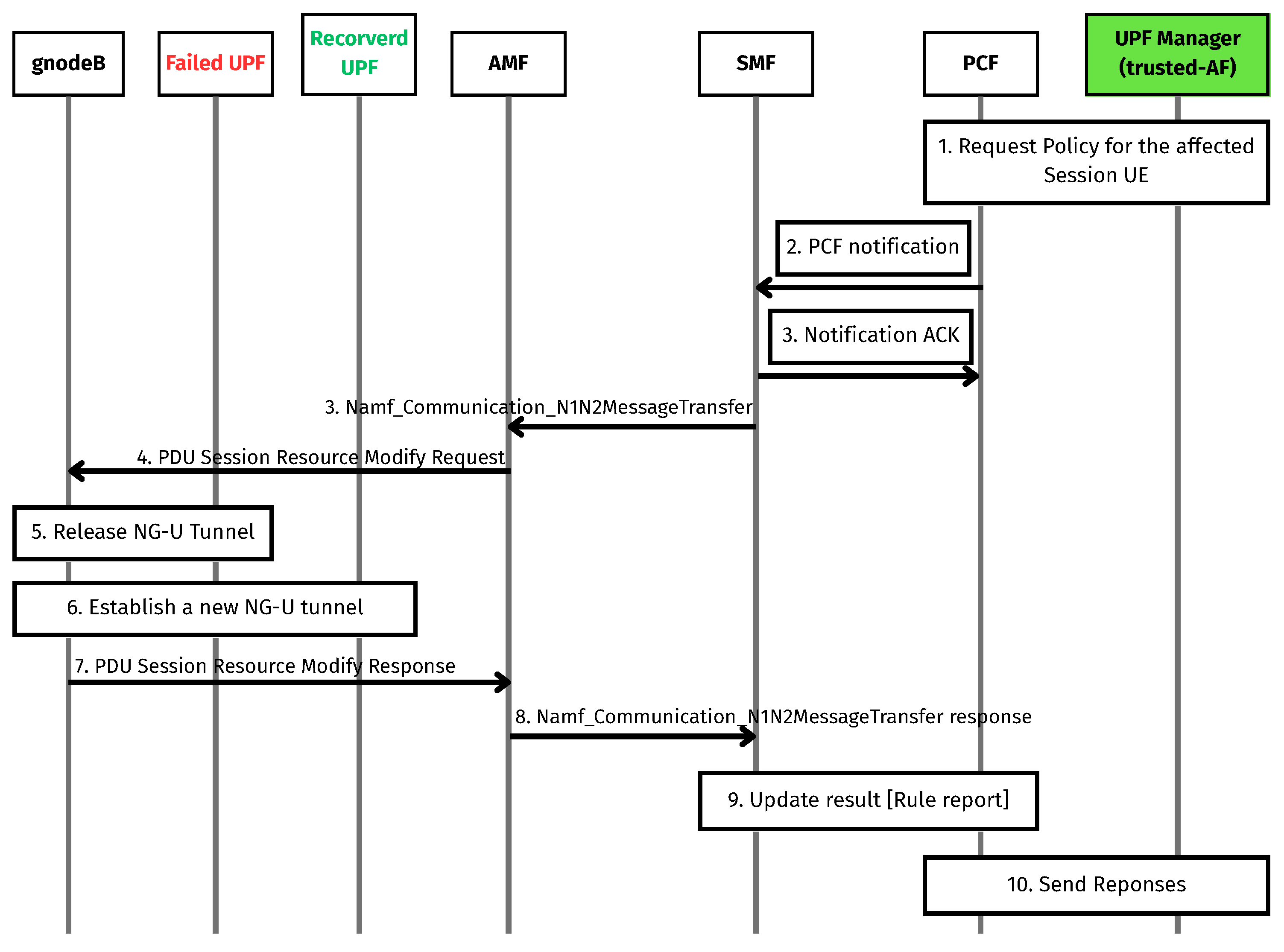
3.2.1. Update Routing by Following 3GPP Procedures
In this section, we present an approach that uses the UPF Manager to interact with 5G core functions to perform the update routing that follows [
27,
28], as illustrated in
Figure 2, which details the procedure that assumes that the UPF Manager acts as a trusted AF. Since the UPF Manager already holds all session data of the failed UPF, it can identify all PDU sessions affected by the failure. Using this information, the UPF Manager initiates or updates policies with PCF regarding the impacted UE PDU sessions, indicating the failure of the old UPF and requesting the serving gNB to switch tunnels to the recovered UPF. Subsequently, PCF sends a notification about these policy updates to SMF. Upon receiving the notification, SMF responds with an acknowledgment back to PCF. The SMF then processes the policy requests for the affected UEs and triggers communication with AMF via the Namf_Communication_N1N2MessageTransfer interface, using N1 and N2 messages. These messages are encapsulated in a PDU Session Resource Modify Request sent to the gNB. The N1 message is left empty, while the N2 message contains the PDU Session Resource Modify Request List IE, which includes all affected PDU sessions represented as individual PDU Session Resource Modify Request IEs. Each request IE includes a User-Plane Failure Indication IE and a UL NG-U UP TNL Information IE, containing the recovered UPF’s IP address and Tunnel Endpoint Identifier (TEID). This information enables the gNB to release the old NG-U tunnel and establish a new one. Upon completion, the gNB replies with a PDU Session Resource Modify Response message, where the Use-Plane Failure Indication Report IE is set to “new transport address allocated”, indicating that the gNB has successfully established the new tunnel. The AMF receives and forwards this response to SMF, which updates rule reports with PCF, and finally, PCF sends a response back to the UPF Manager, completing the update routing procedure.
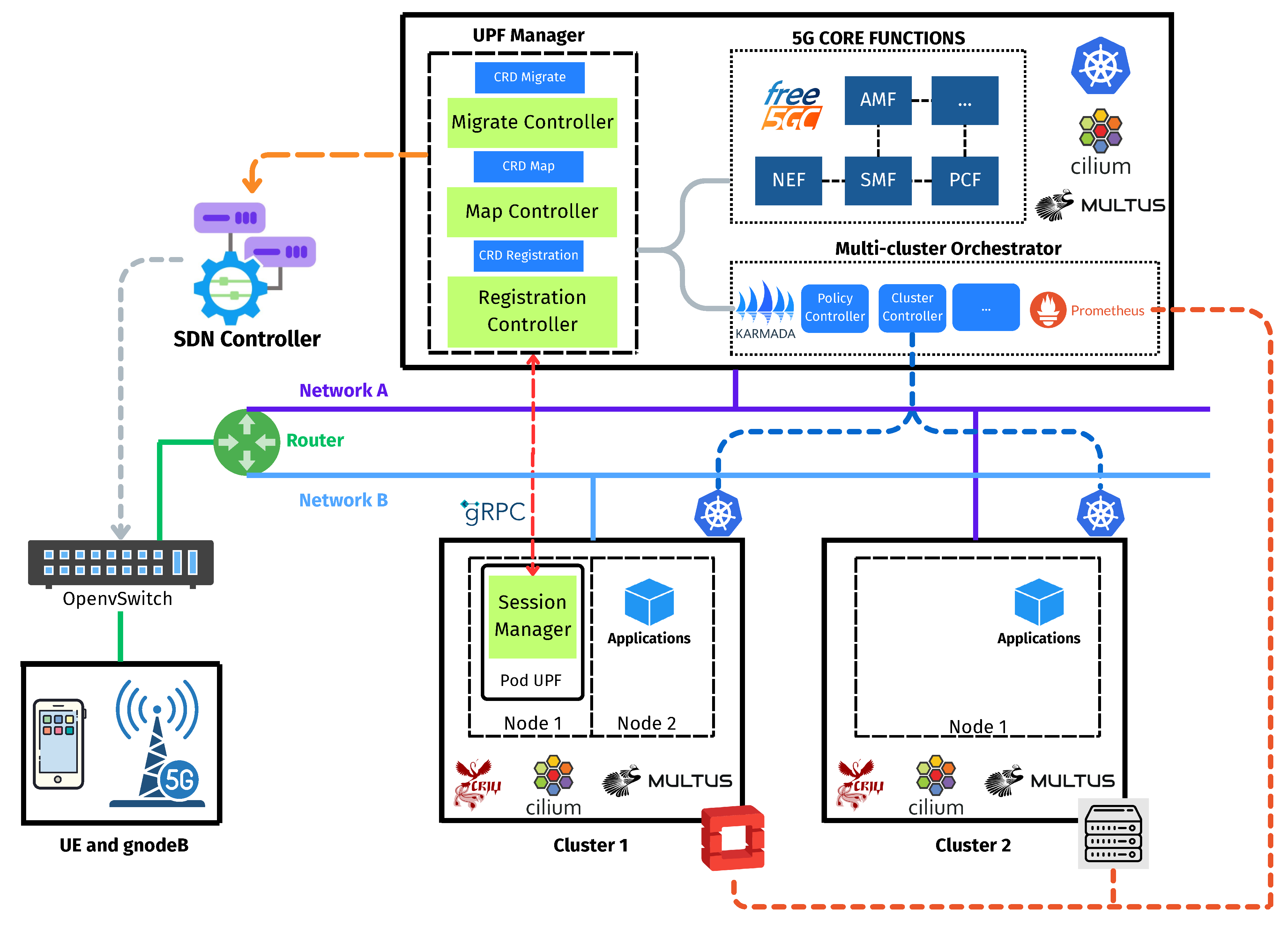
3.2.2. Update Routing by Using External Components
The second approach relies on external components when 3GPP-compliant procedures are unsupported by network elements, such as certain core functions or access nodes, or alternative network management components are available and preferable. In this case, solutions such as Software-Defined Networking (SDN), as depicted in
Figure 3, or dedicated management switches between the gNBs and UPF are usually employed. Upon session restoration, in an SDN-based solution, the UPF Manager communicates with the SDN controller to update traffic-forwarding rules, thereby redirecting GTP traffic to the recovered UPF instance.
5. Results and Discussions
To evaluate the effectiveness of our design on the testbed, we consider two key metrics: UPF Redeployment Time and Service Disruption Time. The UPF Redeployment Time is adopted as a baseline metric, as defined by A. Leiter et al. [
25]. This metric measures the time from UPF failure detection to the creation of a new instance, which is not immediately capable of processing traffic. In our testbed, the metric starts when the UPF Manager detects a faulty UPF and ends when the new UPF Pod, including both the UPF container itself and its Session Manager component, has been fully initialized through Readiness Probes successfully. The Service Disruption Time is defined as the total duration from when a UE becomes disconnected until it successfully regains access to the service. The baseline for this metric is a UPF failure scenario without session continuity.
We evaluate both UPF Redeployment Time and Service Disruption Time under two failure scenarios: (1) failover within the same cluster and (2) cross-cluster failover. Each test case conducts failover procedures 100 times under identical conditions to ensure statistical significance and consistency. Furthermore, before performing the measurements, we ensured that all necessary checkpoint data had already been downloaded and were available in the target to prevent the inclusion of data retrieval time in the evaluation metrics.
In addition to these evaluations, with the Service Disruption Time, we evaluate how cost-effective a system using our proposal is compared to the traditional methods under many reliability level requirements within the same cluster.
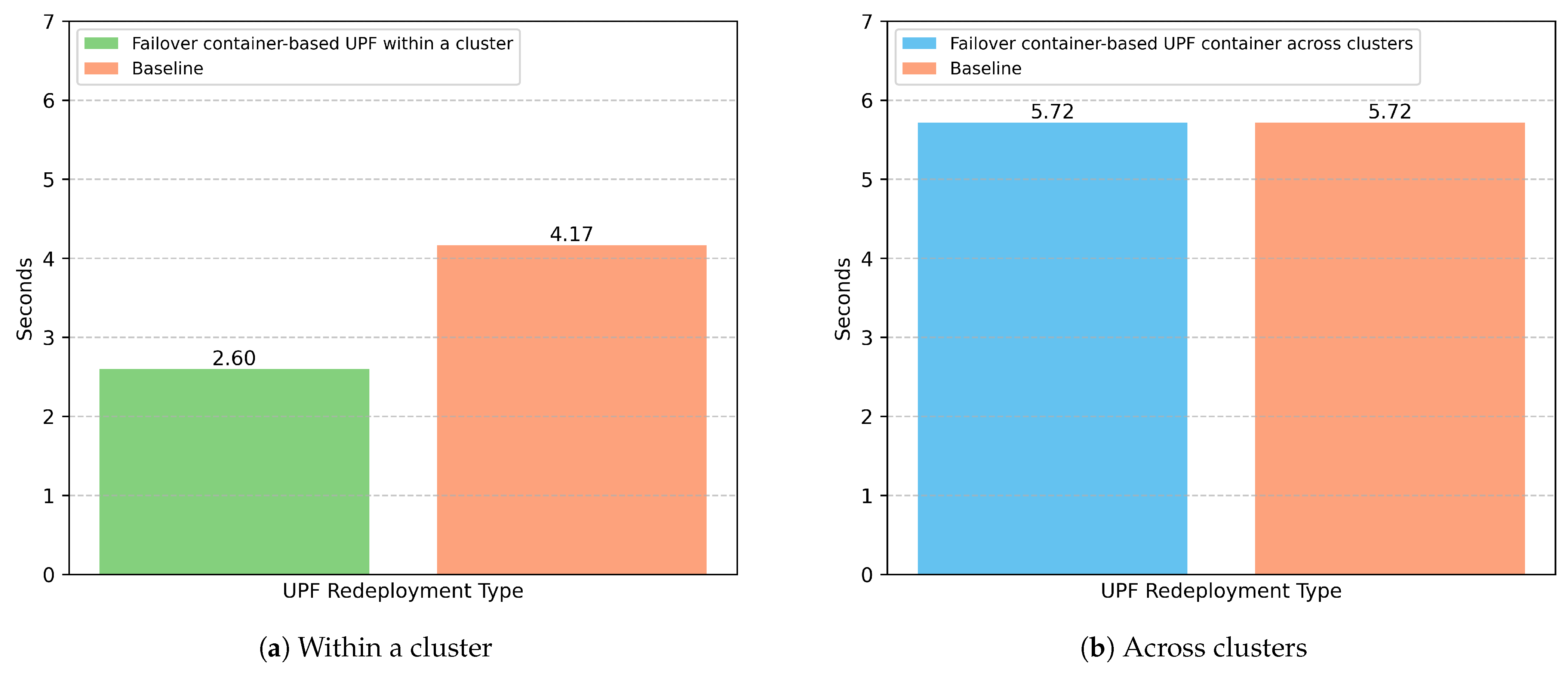
5.1. Performance Evaluation Using UPF Redeployment Time
Figure 5a compares UPF redeployment times within a cluster between our proposed approach and the baseline method. In this comparison, both methods reuse the network interface configuration of the failed UPF pod during restoration. The results show that our approach achieves significantly faster recovery, with a shorter average redeployment time compared to the baseline. This performance gain is mainly due to the fact that our method restores the UPF from a previously saved checkpoint, enabling both the UPF and its associated Session Manager to resume functionality without the need for re-initialization. In contrast, the baseline approach involves redeploying the container from scratch, which entails reinitializing not only the UPF but also its Session Manager component, thereby resulting in a longer overall recovery time. It is worth noting that our testbed utilizes a lightweight open-source UPF. Therefore, the performance gap between our approach and the baseline is expected to widen further when applied to more complex or sophisticated UPF implementations.
Figure 5b shows the UPF redeployment times when the recovered container is launched in another cluster, comparing our proposed approach to the baseline method. In this scenario, both methods exhibit comparable performance, with similar average recovery times. This is expected, as both approaches follow the same strategy: deploying a new UPF instance in a separate cluster, which requires full re-initialization of the UPF and its Session Manager. Unlike the UPF redeployment within a cluster, the restored UPF in this scenario must be assigned a new network interface configuration. As a result, the time required for the UPF to reach the “ready” state is significantly longer. This overhead arises from the additional steps involved in setting up new network interfaces, rather than reusing the previous configuration. This issue has also been discussed in [
25], which highlights the cost of interface provisioning in containerized UPF environments.
In general, by utilizing our UPF Manager as a component for the real-time monitoring of the UPF status, the failure detection and recovery process becomes significantly faster compared to traditional mechanisms such as PFCP heartbeat-based monitoring. Overall, our findings indicate that the failover UPF within a cluster approach offers better recovery performance compared to the other one, but the choice of failover strategy should be made based on the specific failure context, as each method presents different trade-offs in terms of recovery time and system-level requirements.
5.2. Performance Evaluation Using Service Disruption Time
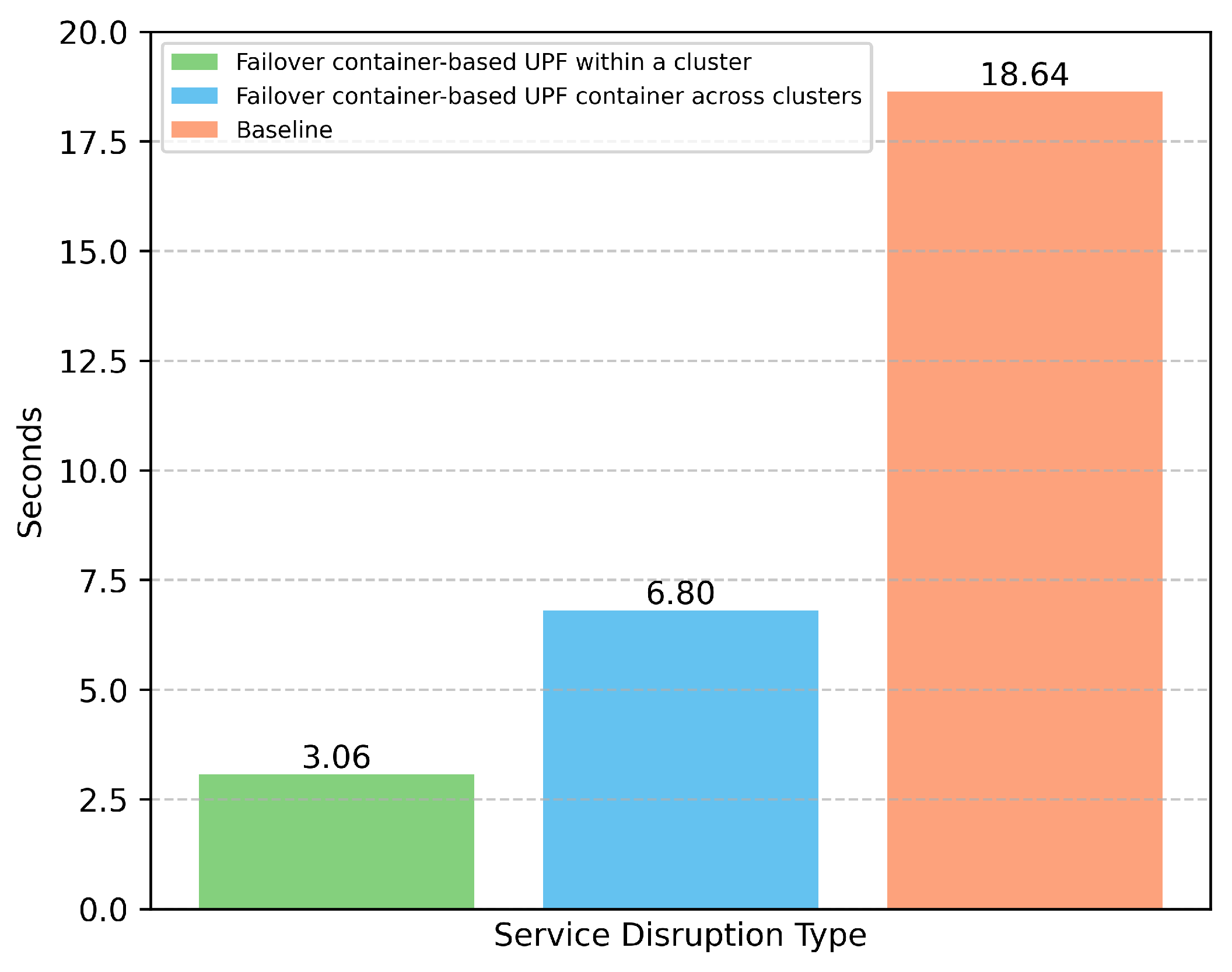
Figure 6 illustrates the comparison of service disruption times between our proposed approaches and the baseline method. Unsurprisingly, the same cluster UPF failover provides the best recovery performance, as the restored UPF only needs to retrieve its session data to resume operation. The other cluster failover, however, takes longer due to the need to not only recover session data but also establish a new N4 PFCP association with the SMF and update routing rules. The baseline method exhibits the longest recovery time, since all affected UEs must re-initiate their PDU sessions from scratch, resulting in a full session re-establishment process. The result of the baseline method is consistent with the findings in [
21].
Regarding the implementation of the 5G Core, the baseline method introduces significant signaling overhead not only between the UE and the core network but also among multiple network functions such as the AMF, SMF, PCF, and others. This issue becomes more critical in private 5G environments, where a large number of connected devices can exponentially increase the number of signaling procedures, placing heavy processing demands on the core network. In contrast, with our proposed failover mechanisms, the UPF is restored rapidly, and in the failover UPF across clusters scenario, the 5G Core only needs to handle routing updates, significantly reducing the signaling burden.
5.3. Evaluation of Cost-Effective Performance Compared with Traditional Methods
To comprehensively evaluate the cost-effectiveness of our proposed approach compared to traditional methods, we introduce a total cost function that captures both the system’s ability to meet the allowed downtime for a given reliability level and the resource usage required to achieve it. The total cost function is defined in Equation (
1):
Here, R denotes the target reliability level, is the overall total cost, represents the resource cost of deploying UPFs, and denotes the downtime penalty cost based on the required reliability level. The coefficients and act as weighting factors that balance the trade-off between resource cost and downtime cost.
The resource cost of UPFs follows the model adopted from [
42,
43] and is expressed in Equation (
2):
where
is the number of containerized UPFs,
is the amount of resources allocated per containerized UPF, and
is the unit price of resource usage.
Similarly, the downtime penalty cost is defined in Equation (
3):
where
is the Service Disruption Time,
represents the maximum allowed downtime according to the target reliability level
R, and
is a penalty coefficient that reflects the cost sensitivity to downtime violations.
To compare and evaluate the cost-effectiveness of our proposed approach against traditional failover methods, we re-implemented two traditional schemes, 1:1 UPF failover and N:M UPF failover, based on their original concepts [
10,
11] in our testbed environment. For the 1:1 UPF failover, the backup UPF is pre-associated with the SMF via the N4 interface before failover occurs, and its PDU sessions are pre-installed manually to mirror the active UPF. In contrast, in the N:M UPF failover scheme, when a failover is triggered, the backup UPF first establishes the N4 association with the SMF; after this, the UPF Manager restores the PDU sessions from the active UPF.
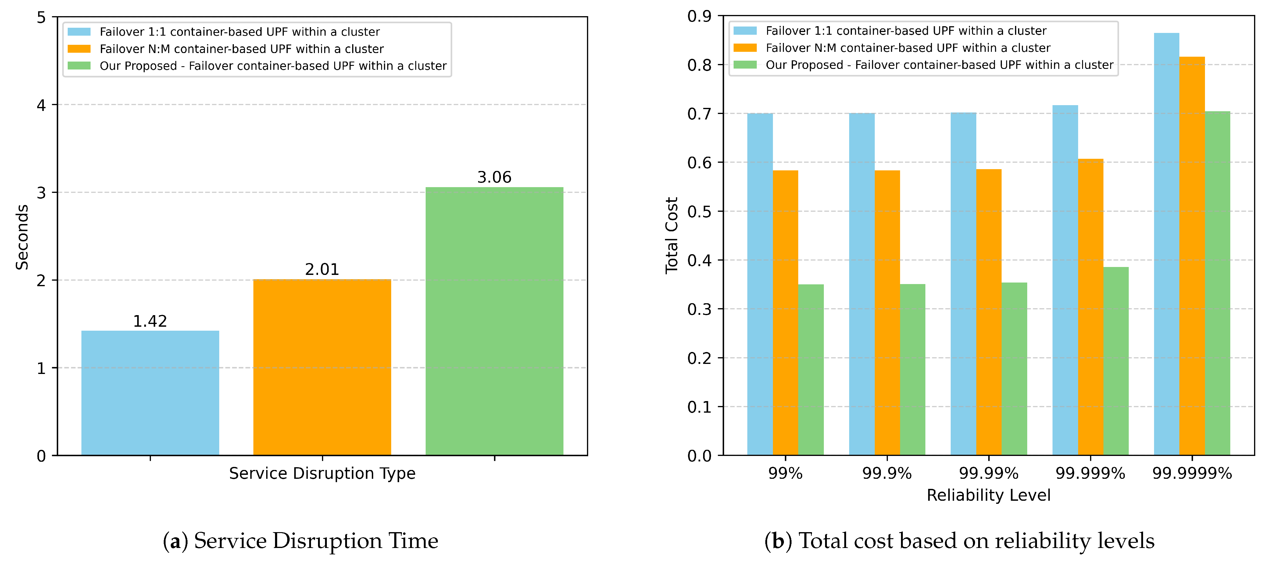
We selected the failover UPF within a cluster method for comparison with traditional approaches because it provides the best service disruption time while avoiding additional delays caused by IP address allocation for the recovered UPF interface. This ensures fairness when compared to traditional methods, where the backup UPF is already pre-launched with an assigned IP address. Although all three methods are deployed within the same cluster, the traditional approaches require the use of OVS to redirect UE’s traffic to the backup UPF because the backup UPF has a different IP address than the active UPF.
Figure 7a presents the results of the Service Disruption Time for our approach compared to traditional methods within the same cluster. Unsurprisingly, our approach exhibits the longest disruption time due to the time required for CRIU to restore the containerized UPF. The 1:1 UPF failover achieves the shortest disruption time since the backup UPF is always ready to serve, followed by the N:M UPF failover, which has the second shortest recovery time. Based on these results, we evaluate the total cost of each method using the cost model defined in Equation (
1). To emphasize resource efficiency, we set
and
, giving higher priority to reducing resource usage. For
, we define
so that the downtime penalty is treated at the same cost scale as operating a single UPF instance. Additionally, for the N:M UPF failover method, we configured the number of backup UPFs to be two-thirds of the number of active UPFs. For
, we define it as the maximum allowed downtime within a one-month period according to the target reliability level.
Figure 7b illustrates the total cost comparison between our approach and the two traditional failover methods. In contrast to the Service Disruption Time results, our approach yields the lowest total cost when the reliability level ranges from 99% to 99.99%. This cost reduction is achieved because our method eliminates the need for pre-running backup instances while still satisfying the required reliability level. As a result, for example, at reliability level 99.99%, our method achieves a 50% cost reduction compared to the 1:1 UPF failover and a 41.5% reduction compared to the N:M UPF failover. When the reliability requirement increases to an ultra-high level of 99.9999%, our approach incurs a higher downtime penalty cost due to longer service disruption time compared to the two traditional methods. However, even under this condition, the overall total cost remains lower than both traditional approaches.
In general, although our proposed method introduces a longer Service Disruption Time compared to the traditional failover mechanisms, it achieves a significantly lower total cost, making it more resource-efficient while still maintaining acceptable reliability trade-offs.
5.4. Research Findings and Limitations
In this paper, we propose a novel design for failover in UPF-containerized deployments that is not only cost-effective but also eliminates the need for traditional redundancy mechanisms, such as continuously running backup instances. Our approach enables real-time fault detection and rapid recovery of UPF containers, which minimizes service disruption and improves overall QoS. The experimental results obtained from our testbed demonstrate that the proposed design fully satisfies the requirements of 3GPP-standardized services and URLLC use cases demanding up to 99.9999% reliability. Accordingly, this design can serve as a complementary alternative to traditional UPF resilience solutions, especially in resource-constrained environments where cost-efficiency is critical.
Additionally, our findings highlight that failover within a single cluster provides faster recovery than cross-cluster failover in terms of both UPF redeployment time and service disruption time, making the first algorithm the preferable choice. Therefore, even in multi-cluster setups, if networking consistency can be ensured (e.g., through VPNs or tunneling), it is feasible to use the first algorithm to achieve quicker recovery with lower complexity.
Despite these promising results, our study has several limitations. First, the feasibility of container-based UPF failover within a cluster depends heavily on the capabilities of CRIU. In production deployments, UPF containers typically leverage data-plane acceleration technologies such as DPDK and VPP to boost throughput and reduce latency by bypassing the kernel and avoiding context-switch overheads. However, CRIU currently lacks support for applications that require these accelerated setups due to diverse setup requirements [
20]. Nevertheless, this limitation does not necessarily imply that CRIU is incompatible with such UPFs. Since CRIU is an open-source project, it can be extended to support checkpointing and restoration for accelerated UPF containers to meet their specialized requirements. Second, our proposed solution assumes stable and reliable communication links between the control-plane and data-plane components. If these connections degrade or fail, incorrect failover actions may be triggered. Third, the UPF Manager acts as a central component for failover operations. This component could introduce a single point of failure and become a scalability bottleneck as the number of UPF instances grows. Moreover, as a central controller, it may become an attractive target for attackers, and any compromise could disable the failover capability of all UPF instances. To address these concerns, future work should explore more advanced solutions, such as high-availability mechanisms and load-balancing strategies.
Although these limitations exist, our proposed failover design provides a promising foundation for future research and practical deployment. It paves the way for more advanced studies and contributes to the ongoing evolution of 5G and beyond infrastructure, where sustainability, resource optimization, and cost-effectiveness are key to delivering next-generation network services.


