Article

Electrical Modeling and Control of a Synchronous Non-Ideal Step-Down Converter Using a Proportional–Integral–Derivative Neural Network Controller

by
Jesús A. Medrano-Hermosillo
1,
Abraham Efraim Rodríguez-Mata
1,*,
Victor Alejandro Gonzalez-Huitron
2,
Francisco-Ronay López-Estrada
3,
Guillermo Valencia-Palomo
4 and
Oscar J. Suarez
5
1
División de Estudios de Posgrado e Investigación, Tecnológico Nacional de México Campus Chihuahua, Instituto Tecnológico de Chihuahua, Ave. Tecnológico #2909, Chihuahua 31310, Mexico
2
División de Estudios de Posgrado e Investigación, Instituto Tecnológico de Querétaro, Tecnológico Nacional de México, Av. Tecnológico s/n esq. Gral. Mariano Escobedo, Colonia Centro Histórico, Querétaro 76000, Mexico
3
TURIX-Dynamics Diagnosis and Control Group, Tecnológico Nacional de México, IT Tuxtla Gutiérrez, Carretera Panamericana km 1080, Tuxtla Gutierrez 29050, Mexico
4
Tecnológico Nacional de México, IT Hermosillo, Av. Tec. 115, Hermosillo 83170, Mexico
5
Facultad de Ingenierías y Arquitectura, Ingeniería Mecatrónica, Universidad de Pamplona, Km. 1 Vía Bucaramanga Ciudad Universitaria Pamplona, Norte de Santander 543050, Colombia
*
Author to whom correspondence should be addressed.
Electronics 2025, 14(2), 357; https://doi.org/10.3390/electronics14020357
Submission received: 29 November 2024 / Revised: 10 January 2025 / Accepted: 13 January 2025 / Published: 17 January 2025
(This article belongs to the Special Issue Advances in Intelligent Systems and Networks, 2nd Edition)

Abstract

:
This article presents a dynamic modeling and control strategy for a non-ideal buck DC–DC (direct current) converter using a PID neural controller. Unlike conventional approaches that rely on fixed-gain PID (Proportional Integral Derivative) controllers, the proposed method dynamically updates the controller’s gain constants to enhance robustness against parametric variations caused by tolerances, wear, or other practical discrepancies. To ensure the neural network’s weight convergence, a Lyapunov-based algorithm is employed, enabling optimal weight adjustments in conjunction with the PID control strategy. The study validates the ANN-based (Artificial Neuronal Network) PID controller under diverse dynamic conditions (input voltage variations, disturbances in voltage sensors, etc.) through numerical simulations, incorporating theoretical derivations and circuit dynamics modeling. The main contribution of this work lies in demonstrating the convergence of the system under the proposed control law, substantiated by Lyapunov stability analysis and comparative simulations against traditional methods in the literature.

1. Introduction

Buck converters are widely used in various applications due to their high efficiency and ability to step-down voltage levels. They are essential in powering portable electronic devices such as smartphones, tablets, and laptops, where efficient power management is crucial to prolong battery life [1]. Additionally, buck converters are employed in renewable energy systems, such as solar photovoltaic systems, to regulate the voltage output from solar panels and optimize energy utilization [2]. In automotive applications, they are used in electric vehicles (EVs) to manage power distribution between the battery, auxiliary systems, and onboard electronics [3]. Furthermore, buck converters play a critical role in industrial automation, telecommunications, and medical devices, ensuring stable voltage levels for sensitive equipment [4]. Other specific applications include parallel converters and multilevel converters. However, a significant challenge in these systems is that each parallel converter possesses its own uncertain parameters. As the number of converters increases, so does the complexity and the number of unaccounted parameters. Consequently, if the converters rely on controllers designed based on the system’s theoretical dynamics, the real-time performance may deviate significantly from the theoretical predictions. As we can see, step-down converters are essential in modern electronics, where maintaining a stable output voltage under varying load conditions is critical. Achieving this stability requires a robust system capable of addressing challenges such as component tolerances, sensor disturbances, and fluctuations in input voltage. The control law plays a pivotal role in overcoming these issues, ensuring the converter operates reliably under diverse conditions. Our proposed solution emphasizes adaptability within the control law, effectively mitigating parametric variations, input disturbances, and other uncertainties to ensure optimal performance. To clarify the diverse definitions in the present approach, see the Table 1.
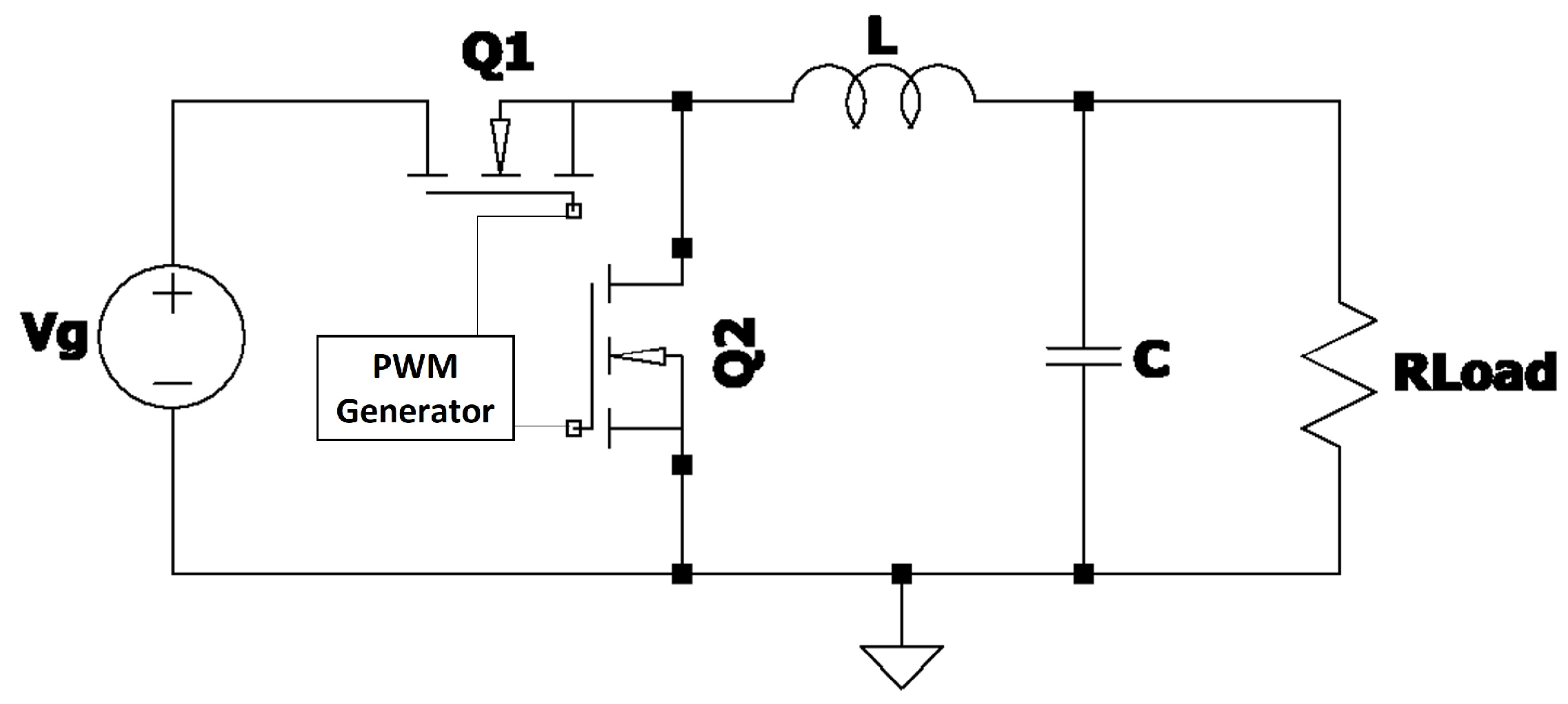
A buck converter is a non-isolated power converter (see Figure 1) that steps down the input voltage to a lower output voltage. It is widely used in cell phone chargers, power systems in electric vehicles, and other applications [5]. The key components of a buck converter include the input voltage ( V g ), switching transistor (Q), diode (D), inductor (L), output capacitor (C), and load ( R Load ). Practical implementations typically fall into two categories: synchronous and non-synchronous models. The synchronous model is preferred for its higher efficiency, achieved by replacing the diode in the nonsynchronous design with a transistor, which enhances performance (see Figure 2) [6].
In order to see the dynamic behavior of the system, this study analyzes and calculates the dynamic equations for the synchronous step-down converter based on the small-signal model, where the small signal analysis is the approach that describes a circuit’s behavior without taking into account the dynamics at high frequencies. Some relevant works using this technique can be seen in [5,7,8]. Where once we have the dynamic model of the system, a control law is implemented to maintain the desired voltage.
A DC–DC converter uses many control techniques to maintain a constant voltage or current, where the method used to maintain a constant output voltage is called voltage mode control [9]. According to [10], the authors describe the performance of the most traditional controllers in recent years, comparing PID, type II, and type III controllers. In their study, type II and type III controllers perform better with the K-factor technique than with PID. Another important topic is the optimal tuning of DC–DC converters, where these approaches are more efficient than traditional tuning methods [11]. Specifically, optimal adaptive gain strategies have been proposed for hybrid power systems to enhance performance and stability [12]. Furthermore, teaching–learning-based optimization methods combined with adaptive fuzzy logic controllers demonstrate significant improvements in frequency control within microgrid applications [13]. The problem with these works is that gains are based on plant models, so tuning is based on exact models, whereas in real life, there are many perturbations such as parametric variations, tolerances, noise, etc. Consequently, other works have decided to update the control gains to guarantee good performance in other conditions.
Paper [14] presents a PID controller for a microgrid that is resilient to load dynamics, harmonics, and unidentified loads. Their methodology illustrates that islanded microgrids can deliver superior tracking performance and secure operation. Alternatively, Ref. [15] introduces a PID controller based on a backpropagation artificial neural network. The artificial neural network computes the requisite gains according to the transient and steady-state components of the step response, contingent upon the system’s desired output. Consequently, PID controllers utilizing artificial neural networks offer an efficient approach for regulating diverse dynamic systems. Additional pertinent studies are presented in [16], which enhances neural network-based PID controllers for second-order mechanical systems; Ref. [17], which amalgamates backpropagation neural networks with gray wolf optimization; Ref. [18], where a deep PID neural network is employed for accurate temperature regulation; and Ref. [19], which implements Lyapunov-based adaptive PID controllers for Buck converters. In contrast to the method presented in [19], which utilizes a Lyapunov-based adaptive PID controller that requires manual re-tuning, our approach combines a PID neural network with a Lyapunov-based learning algorithm for online gain adaptation. This enhances resilience to disturbances, eradicates the need for re-tuning, and optimizes performance amid uncertainties and parameter fluctuations, with possible applications extending beyond Buck converters. Model Reference Adaptive Control (MRAC) improves power electronics performance and reliability. MRAC regulates rectifiers, inverters, DC–DC converter voltage, Buck, and Boost converters [20,21]. It works better in three-phase constant-voltage constant-frequency inverters [22] and single-phase shunt active power filters [23]. DC–DC boost converter PI controllers and photovoltaic maximum power point tracking use MRAC [24,25]. Even power plants use it [26]. These studies demonstrate that MRAC can handle parameter uncertainties, improve transient response, and ensure system stability in power electronics applications.
According to the literature, a neural network coupled to a self-tuned PID controller effectively controls a system. Thus, the proposed work calls for using this methodology in a synchronous non-ideal step-down converter, where the main difference from other works is the use of the Lyapunov stability theory to guarantee convergence in weights and gains between PID controllers. To simplify the weight adaptation equations, selecting the Lyapunov candidate function, which is derived from the Lyapunov stability theory, is essential. Hence, the primary objective of this work is to demonstrate that the proposed algorithm—A PID Neural Network Controller—outperforms traditional fixed-gain methods, such as Type II, Type III, and the widely used PID controller, which is often tuned using the Ziegler–Nichols method. It is important to acknowledge the growing popularity of adaptive methods and advanced control laws in modern applications. These methods, along with advanced control systems, are summarized in Table 2, which highlights techniques used for regulating Buck-type converters. Nonetheless, the central focus remains on showcasing the performance of the proposed algorithm in comparison to the most commonly employed methods in the field today.
The document is organized as follows: Section 2 presents the dynamic modeling of the converter. Section 3 details the stability and analysis of the controller. Section 4 provides the numerical simulation of the Buck converter with the PID neural network controller. Finally, in Section 5, the conclusions and future work are presented.

2. Dynamic Modeling of a Synchronous Non-Ideal Buck Converter

In order to determine the switching converter operation, a small-signal analysis is used to solve it. The following steps must be followed in order to perform this analysis:
(a)
State-space averaging method.
(b)
Perturbation.
(c)
Linearization.
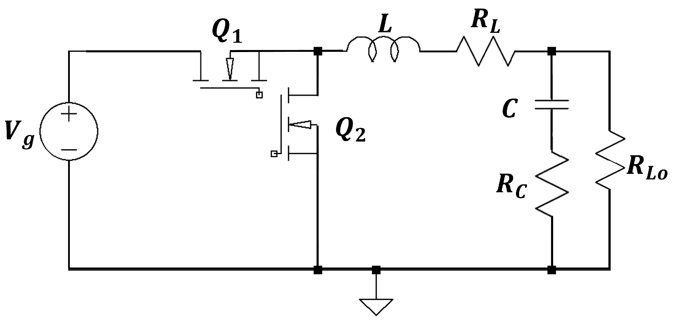
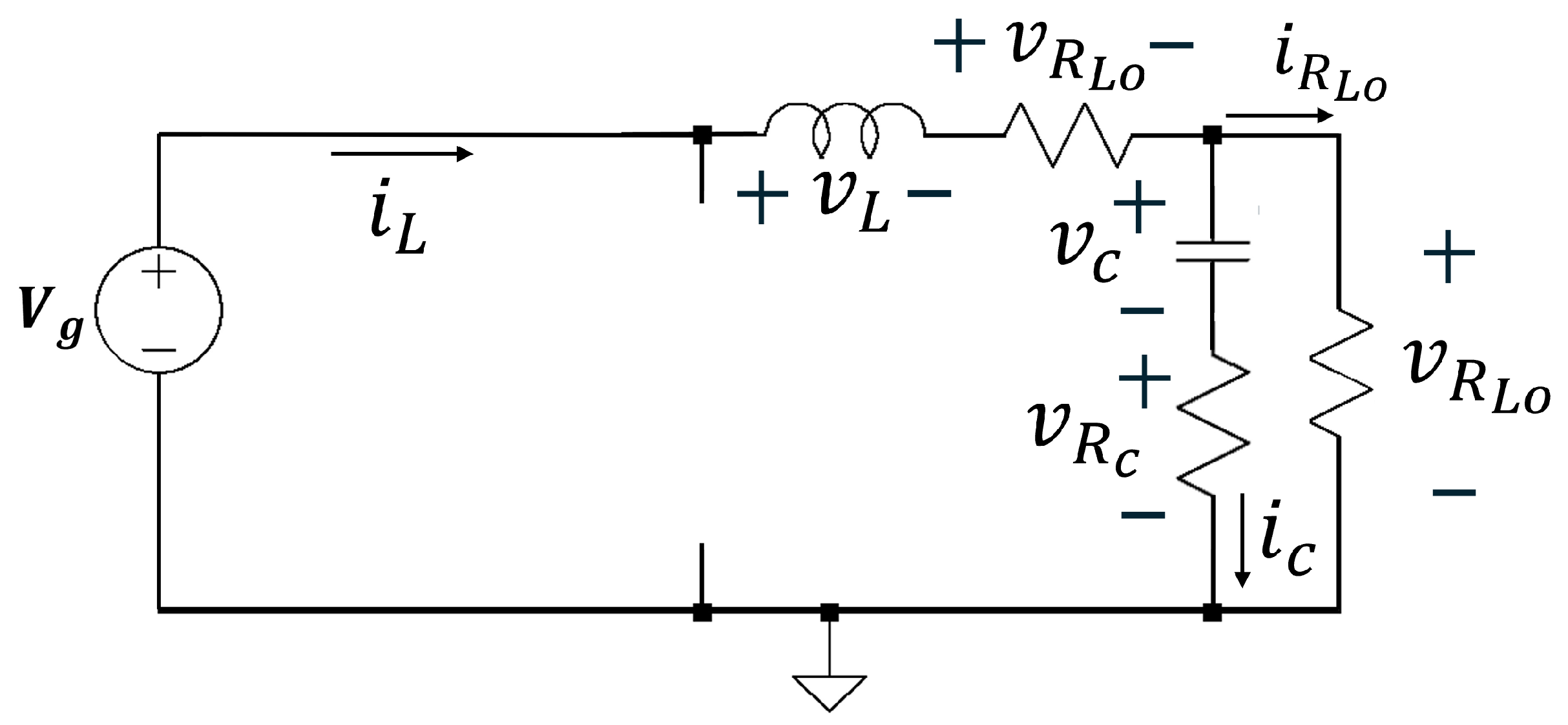
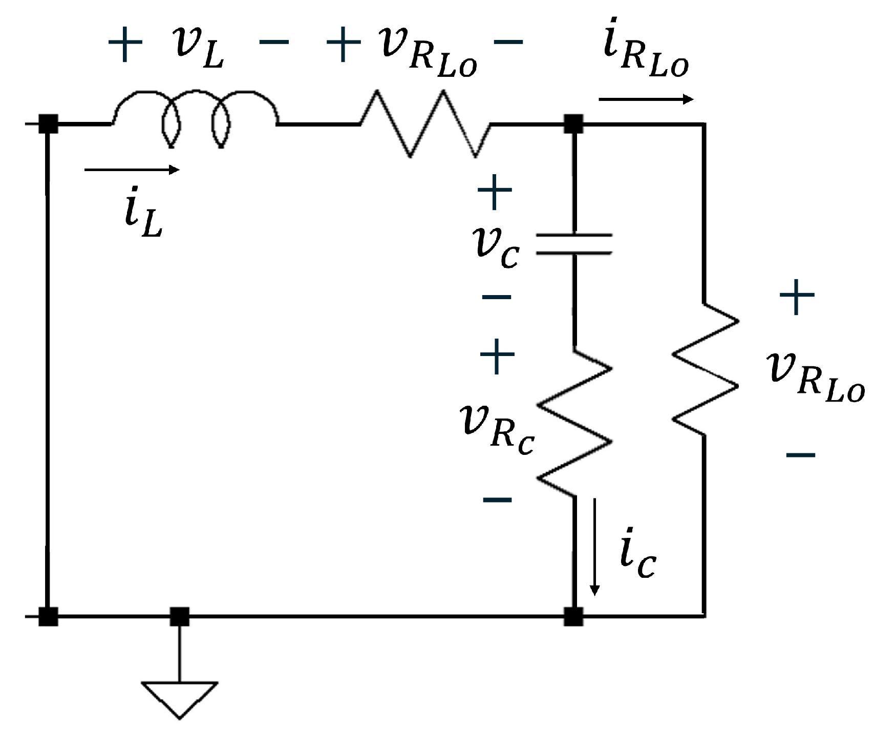
Therefore, the average model in the state space must first be obtained [35]. This can be achieved by first obtaining the different stages of the circuit. The circuit shown in Figure 3 is used to achieve this, where non-ideal terms, such as the internal resistor of the inductor ( R L ) and the internal resistance of the capacitor ( R C ), are displayed in the circuit. In the first stage, when Q 1 is turned on, and Q 2 is turned off, the circuit behaves as in Figure 4. Alternatively, when Q 1 is turned off, and Q 2 is turned on in the second stage, the circuit looks as in Figure 5. Through Kirchhoff’s laws, the following equations are derived from the previous stages, which were calculated based on the load resistance. For the first stage, applying Kirchhoff’s voltage law to the inductor mesh and Kirchhoff’s current law to the load resistor’s voltage node, the resulting equation can be seen in Equation (1).
L d i L d t = v g v c R C i L i R L o R L i L C d v c d t = i L i R L o
On the other hand, the equations for the second stage are expressed as Equation (2).
L d i L d t = v c R C i L i R L o R L i L C d v c d t = i L i R L o
Thus, based on [5,35], the averaged differential equations can be expressed as
L d i L d t = d v g v c R C i L i R L o R L i L C d v c d t = i L i R L o
where d is the duty cycle of the applied PWM. Once the averaged model has been obtained, perturbing the system can be performed in the next step. To carry out this step, it is necessary to consider that every variable has DC and AC terms. Thus, each variable can be expressed as:
i L = I L + i L ˜ v g = V g + v g ˜ v c = V c + v c ˜ i R L o = I R L o + i ˜ R L o d = D + d ˜
where uppercase variables represent DC terms, while AC terms are represented by the values with a tilde. Substituting (4) into (3) gives
L d I L + i L ˜ d t = D + d ˜ V g + v g ˜ V c + v c ˜ R C I L + i L ˜ I R L o + i ˜ R L o R L I L + i L ˜
C d V c + v c ˜ d t = I L + i L ˜ I R L o + i ˜ R L o
Due to the constant state of DC signals, their derivatives will be zero. Based on what was mentioned, and by neglecting the second-order terms from the previous equation (basically, two AC elements multiplied), the steady-state differential equation can be simplified as
L d i L ˜ d t = D v g ˜ + V g d ˜ v ˜ c R C i ˜ L i ˜ R L o R L i ˜ L C d v ˜ c d t = i ˜ L i ˜ R L o
The above equation is a generalized version of the non-ideal Buck converter, where the objective of the proposed work is to maintain the output voltage based on the duty cycle of the transistors. Therefore, the output voltage must first be calculated, which is performed as follows:
v ˜ R L o = v ˜ c + R C i ˜ L i ˜ R L o
To find the transfer function, it is necessary to apply the Laplace transform to Equations (7) and (8), where the transformation and combination result in
v ˜ R L o ( s ) = [ D v ˜ g ( s ) + V g d ˜ ( s ) R L i ˜ L ( s ) s L i ˜ L ( s ) ] R C C s + 1 L C s 2 + C R C + R L s + 1
Finally, according to [5], the small-signal transfer function can be obtained by G v ˜ R L o | d ˜ = v ˜ R L o ( s ) d ˜ ( s ) | v ˜ g ( s ) = i ˜ L ( s ) = 0 . Thus, using (9), the dynamic behavior of the non-ideal Buck converter is computed as
v ˜ R L o ( s ) d ˜ ( s ) = V g R C C s + 1 L C s 2 + C R C + R L s + 1
The derived transfer function captures the parasitic parameters of various components, including the resistances of the capacitor and inductor within the converter. This model extends beyond previous works, such as [19,36,37], by offering a more detailed representation. However, certain parasitic parameters, such as the transistor resistances, are excluded because of their relatively minor impact compared to the larger resistances of other elements, making them less significant. In addition, the proposed algorithm is specifically designed to mitigate such cases effectively. However, if additional parameters need to be included or a control law with fixed gains is intended, it is crucial to address the factors traditionally omitted in the Buck converter model. For example, the traditional Buck converter should account for factors such as the diode’s voltage drop and the MOSFET’s resistance. The following considerations detail these aspects:
  • R o n : on-state resistance of the MOSFET.
  • R o f f : off-state resistance of the MOSFET.
  • V d i o d e : forward voltage drop of the diode.
  • Dead-time distortion: delay between switching transitions of the MOSFETs.
During the first stage (MOSFET Q 1 on, diode off), the updated equations are
L d i L d t = V g V c i L R o n R C i L i R L 0 C d V c d t = i L i R L 0
On the other hand, during the second stage (with MOSFET Q 1 off and the diode on), the equation is similar to Equation (2). However, it requires adding the diode voltage to the first equation, where the threshold voltage for a silicon diode is approximately 0.7 V .
Furthermore, a comprehensive analysis requires considering dead-time distortion, which introduces a brief interval between the two stages, causing a discontinuity in the inductor current. This phenomenon reduces efficiency at low duty cycles, and can be modeled by incorporating a delay term, t dead , into the switching signal. During the dead-time, the inductor current can be approximated as
i L ( t + t d e a d ) i L ( t ) V d i o d e · t d e a d L .
These updated equations and considerations are especially relevant for low duty cycle operation, where the effects of R o n , V d i o d e , and dead-time are magnified, impacting efficiency and steady-state performance. Several approaches to mitigate this issue are discussed in [38,39]. However, it is important to note that, in the specific case of the proposed algorithm, the control law is sufficiently adaptable to mitigate the effects of uncertain parameters, as long as the control law and neural network updates are considerably faster than the system dynamics.

3. PID Neural Network Controller

3.1. Artificial Neural Network

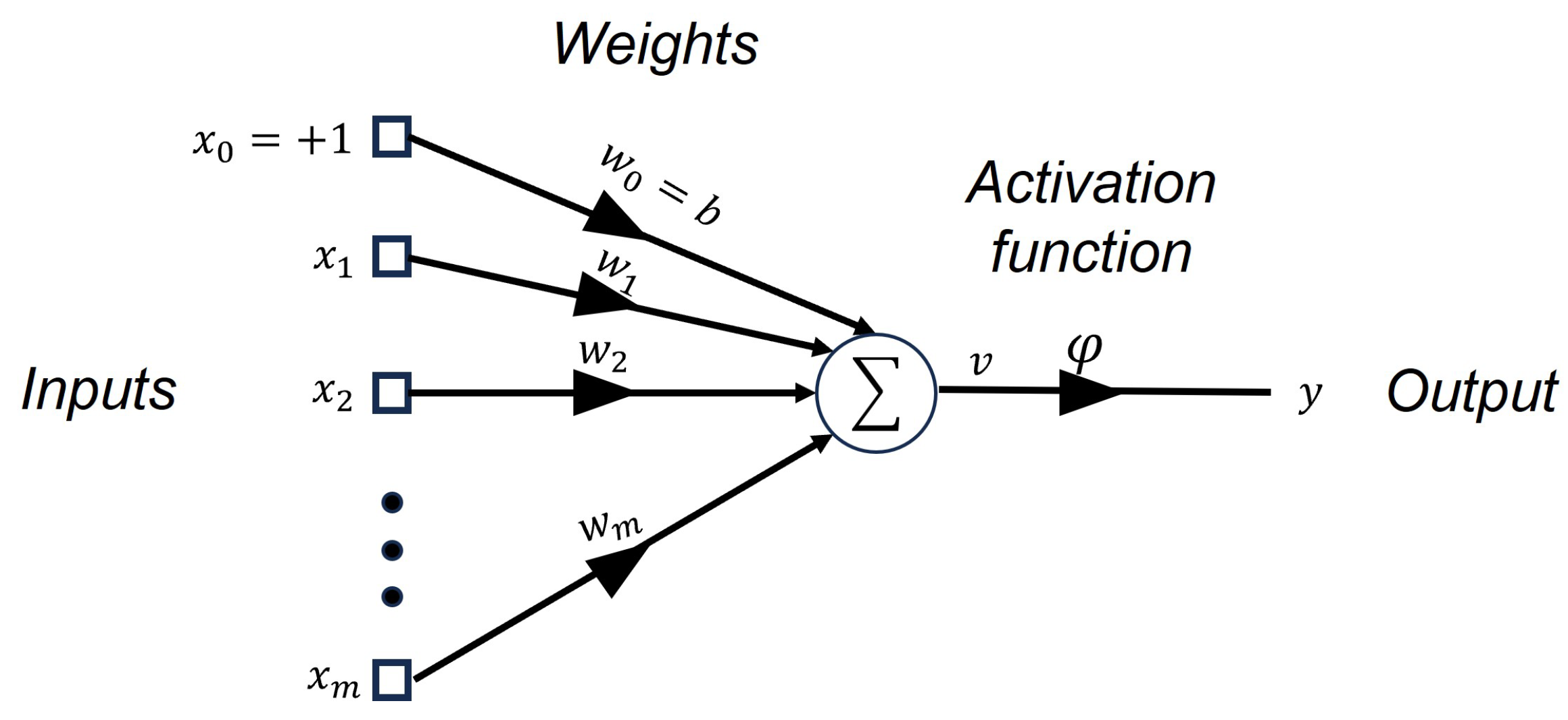
An artificial neural network (ANN) is a machine learning system designed to mimic human neural activity, enabling it to learn and adapt [40]. The architecture of the ANN depends on its application, where a general structure of a single artificial neuron can be seen in Figure 6. Based on the architecture of the ANN, the output of the ANN is computed by y k ( n ) = φ k v k , where v k = φ k k = 0 m x k . In order to learn a neural network, the delta rule algorithm is used where the diverse weights are updated as follows.
w k n + 1 = w k n + Δ w k n
The delta rule algorithm is used to update the different weights of the neural network, where it is essential to know the rate of change of each of the weights. To determine the rate of weight change, gradients are needed, which determine the direction of error between the reference and the neural network output. Considering the above, a negative gradient is necessary to minimize the error (since the delta rule requires a change in weight in the opposite direction). The aforementioned can be applied by Equation (14).
Δ w k n = γ ξ ( n ) w k ( n )
where ξ = 1 2 e k ( n ) 2 = 1 2 d k ( n ) y k ( n ) 2 and γ R + . Therefore, to compute ξ ( n ) w k ( n ) , it is necessary to do the following:
ξ ( n ) w k ( n ) = ξ ( n ) e k ( n ) e k ( n ) y k ( n ) y k ( n ) v k ( n ) v k ( n ) w k ( n )
Thus,
ξ ( n ) w k ( n ) = d k ( n ) y k ( n ) y k ( n ) v k ( n ) v k ( n ) w k ( n )
Finally, the learning algorithm of the artificial neural network can be determined by (14) and (16) in (13),
w k n + 1 = w k n + γ d k ( n ) y k ( n ) y k ( n ) v k ( n ) v k ( n ) w k ( n )

3.2. PID Self-Tuning Algorithm Based on ANN

In the power system industry, DC–DC converter control is a topic of discussion. One of the most famous linear controllers for converters is the PID (as well as lead, lag, and lead-lag compensators), which provides robustness and simplicity when applied in practice [41]. Nevertheless, to enhance performance, an incremental PID algorithm is proposed in this study that solves the problem of accumulating store errors. Using the incremental PID algorithm, the control law can be computed as [42]
u ( n ) = u ( n 1 ) + Δ u ( n ) Δ u ( n ) = k P ( n ) [ e ( n ) e ( n 1 ) ] + k I ( n ) e ( n ) + k D ( n ) [ e ( n ) 2 e ( n 1 ) + e ( n 2 ) ]
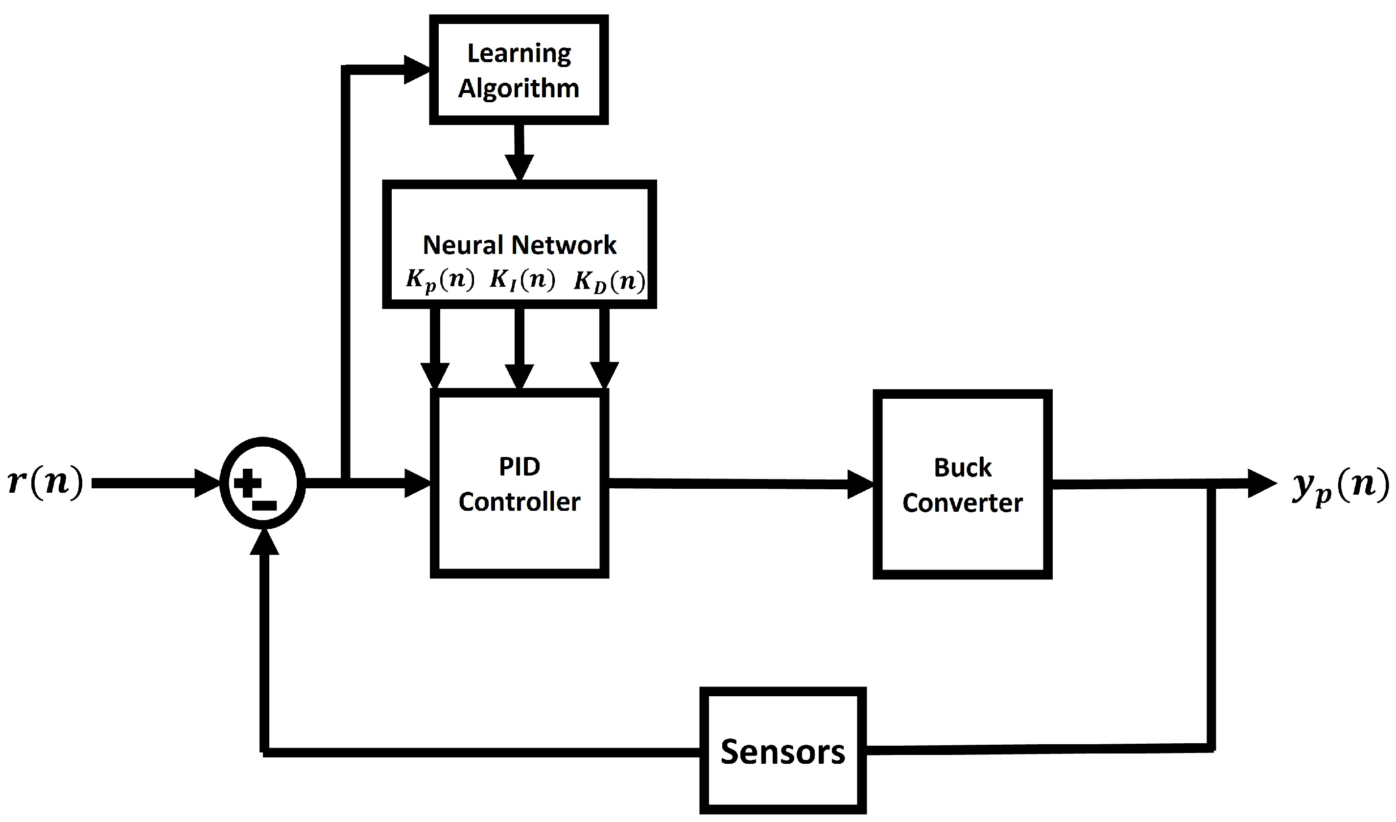
where k P ( n ) , k I ( n ) , k D ( n ) R + . In general, these gains tend to be constant, which creates a problem since the controller must be tuned every time a plant parameter changes. This problem is solved with ANN, where the control block diagram can be seen in Figure 7. To compute the PID gains, the subsequent paragraphs present the theorem for choosing the parameters to update the weight of the ANN.
Theorem 1.
An ANN using the following update of the weights satisfies the convergence of the gains k P ( n ) , k I ( n ) , k D ( n ) of a PID controller:
w k n + 1 = w k n γ δ 2 Ψ k Φ k y k ( n ) v k ( n ) v k ( n ) w k ( n )
where
Ψ k = 2 δ 1 δ 2 e ( n ) + Δ e ( n ) + 2 δ 2 w k ( n ) Φ k = δ 1 2 e ( n ) + Δ e ( n ) + 2 δ 1 δ 2 w k ( n )
Proof. 
The following Lyapunov candidate function is proposed in order to guarantee convergence of both, the error signal and the diverse weights of the ANN:
V k ( n ) = δ 1 e k 2 ( n ) + δ 2 w k 2 ( n ) + 2 δ 1 δ 2 e k ( n ) w k ( n )
where δ 1 , δ 2 R + . According to the delta rule, the above Lyapunov function can be converged by
V k ( n + 1 ) = V k ( n ) + Δ V k ( n )
At steady state, the system can be described as
Δ V k ( n ) = V k ( n + 1 ) V k ( n ) = 0
Taking (21) in (23) gives
[ δ 1 e k 2 ( n + 1 ) + δ 2 w k 2 ( n + 1 ) + 2 δ 1 δ 2 e k ( n + 1 ) w k ( n + 1 ) ] [ δ 1 e k 2 ( n ) + δ 2 w k 2 ( n ) + 2 δ 1 δ 2 e k ( n ) w k ( n ) ] = 0
Suppose that Δ w k ( n ) = w k ( n + 1 ) w k ( n ) and Δ e k ( n ) = e k ( n + 1 ) e k ( n ) . Consequently,
δ 1 Δ e k 2 ( n ) Δ w k ( n ) + Δ e k ( n ) Δ w k ( n ) [ 2 δ 1 e k ( n ) + 2 δ 1 δ 2 w k ( n ) ] + δ 2 Δ w k ( n ) + 2 δ 1 δ 2 [ Δ e k ( n ) + e k ( n ) ] + 2 δ 2 w k ( n ) = 0
It is possible to assume Δ e ( n ) Δ w ( n ) = e ( n ) w ( n ) if the sampling time is too low. As a result,
Δ w ( n ) = 1 δ 2 Ψ k + Φ k e ( n ) w k ( n )
where
Ψ k = 2 δ 1 δ 2 e ( n ) + Δ e ( n ) + 2 δ 2 w k ( n ) Φ k = δ 1 2 e ( n ) + Δ e ( n ) + 2 δ 1 δ 2 w k ( n )
By substituting (26) into (17), (19) is obtained. In this way, the proposed theorem can be used to prove the convergence of the Lyapunov function. □

3.3. Derivation of Partial Derivatives in Theorem 1

The partial derivatives in Equation (19) are derived as follows: 1. Neuron output: The ANN output is given by
y k ( n ) = φ k ( v k ( n ) ) where v k ( n ) = i = 0 m w k i x i ( n ) .
2. Linear activation function: This function depends on the activation function chosen by the user, which can include options such as sigmoid functions, hyperbolic tangent functions, and others. For example, assuming φ k ( v k ) = v k , the derivative becomes
y k ( n ) v k ( n ) = 1 .
with a different activation function, this partial derivative can be expressed as y k ( n ) v k ( n ) = y ˙ k ( n ) .
3. Derivative with respect to weights: from v k ( n ) = w k i x i ( n ) , the partial derivative with respect to w k ( n ) is
v k ( n ) w k ( n ) = x k ( n ) .
Combining these results, the weight update rule in Equation (19) ensures convergence by incorporating the gradient descent mechanism based on Lyapunov stability analysis.
By dynamically updating PID gains k P ( n ) , k I ( n ) , k D ( n ) , Theorem 1 ensures the convergence of ANN weights w k . The proof guarantees the asymptotic stability of both the error signal and the ANN weights using the Lyapunov stability criterion and the candidate function V k ( n ) . Although Theorem 1 is derived for a nonideal Buck converter, its convergence mechanism and stability analysis apply to other dynamic systems with PID structures. The weight update rule is given by
w k ( n + 1 ) = w k ( n ) γ δ 2 Ψ k Φ k y k ( n ) v k ( n ) v k ( n ) w k ( n )
Power electronic systems such as boost converters, inverter controls, and highly non-linear systems that require real-time adaptation to disturbances and parameter variations can benefit from the ANN-based PID controller. Future work will focus on formalizing this approach in various control scenarios to demonstrate its broad applicability.
A real-time single-layer artificial neural network (ANN) dynamically updates the gains of the PID controller k P ( n ) , k I ( n ) , k D ( n ) . The network architecture and its components are detailed as follows:
  • Inputs: The ANN receives three inputs:
    e ( n ) ( current error signal ) , Δ e ( n ) = e ( n ) e ( n 1 ) ( change in error ) , Δ e 2 ( n ) = ( e ( n ) e ( n 1 ) ) 2 ( squared change of error ) .
    The mentioned inputs represent the error between the system’s output and the reference signal. These inputs require only the errors from previous states to be obtained, simplifying the data acquisition process.
  • Outputs: The proposed neural network features three output neurons, which represent the gains K P , K I , and K D of the PID controller, where the control law will be computed as
    Δ u ( n ) = k P ( n ) e ( n ) e ( n 1 ) + k I ( n ) e ( n ) + k D ( n ) e ( n ) 2 e ( n 1 ) + e ( n 2 )
    In other words, each gain of the aforementioned controller will have the architecture shown in Figure 6.
  • Activation function: A linear activation function is employed to ensure stability and simplify gradient calculations during weight updates. The output of the neuron is given as
    y k ( n ) = φ k ( v k ) = v k , where v k = i = 0 m w k i x i ( n ) .
    Here, x i ( n ) are the ANN inputs, and w k i are the network weights.
  • Parameter selection ( δ 1 and δ 2 ): The Lyapunov candidate function V k ( n ) (Equation (21)) includes the parameters δ 1 and δ 2 , which play a critical role in ensuring the asymptotic stability of the ANN weights and error signal. The Lyapunov function is defined as
    V k ( n ) = δ 1 e k 2 ( n ) + δ 2 w k 2 ( n ) + 2 δ 1 δ 2 e k ( n ) w k ( n ) .
    The parameters δ 1 and δ 2 are chosen as small positive real numbers ( δ 1 , δ 2 R + ) to balance the convergence rate of the error e k ( n ) and the weight updates w k ( n ) . Specifically,
    A larger value of δ 1 accelerates the error minimization process.
    δ 2 moderates the weight updates to prevent instability caused by excessive adjustments.
    These parameters are empirically tuned via simulations to achieve fast and stable convergence without overshoot or oscillations.
The ANN dynamically adjusts the PID gains in real-time by utilizing error terms as inputs and a linear activation function. The parameters δ 1 and δ 2 , validated through Lyapunov stability analysis, ensure robust convergence and stability under varying system dynamics and disturbances.
The suggested ANN-based PID controller can be adapted for DC–DC converters functioning in parallel or interleaved arrangements, where load distribution and current equilibrium are essential. In parallel systems, each converter can implement the proposed adaptive PID control strategy to dynamically adjust its output in response to fluctuating load demands and system disturbances, thereby ensuring uniform current distribution. This configuration has practical applications in distributed power systems, data centers, electric vehicle battery chargers, and renewable energy systems, where modular DC–DC converters function synergistically to enhance efficiency and reliability. Future efforts will concentrate on the meticulous execution and verification of this methodology in relevant scenarios to tackle the control complexities arising from interleaving and dynamic load fluctuations.

3.4. Avoiding Natural Resonances

The proposed approach, which employs a neural network-optimized PID controller, demonstrates a rapid time response resembling a quasi-Dirac pulse. This behavior enables swift tracking and minimizes steady-state error. However, it also risks exciting the system’s natural resonances, particularly in converters with lightly damped dynamics. To mitigate this issue, a low-pass filter can be applied to the control signal to smooth sudden transitions and limit high-frequency components that may induce resonances. However, adding this filter could introduce signal phase delays.
An alternative solution is to adjust the neural network parameters to include a damping term or to limit the rate of change of the control action. These adjustments enhance system stability while maintaining effective tracking performance. Future work will focus on implementing these strategies and evaluating their performance in experimental scenarios.

4. Control of a Synchronous Non-Ideal Step-Down Converter Using a PID Neural Network Controller

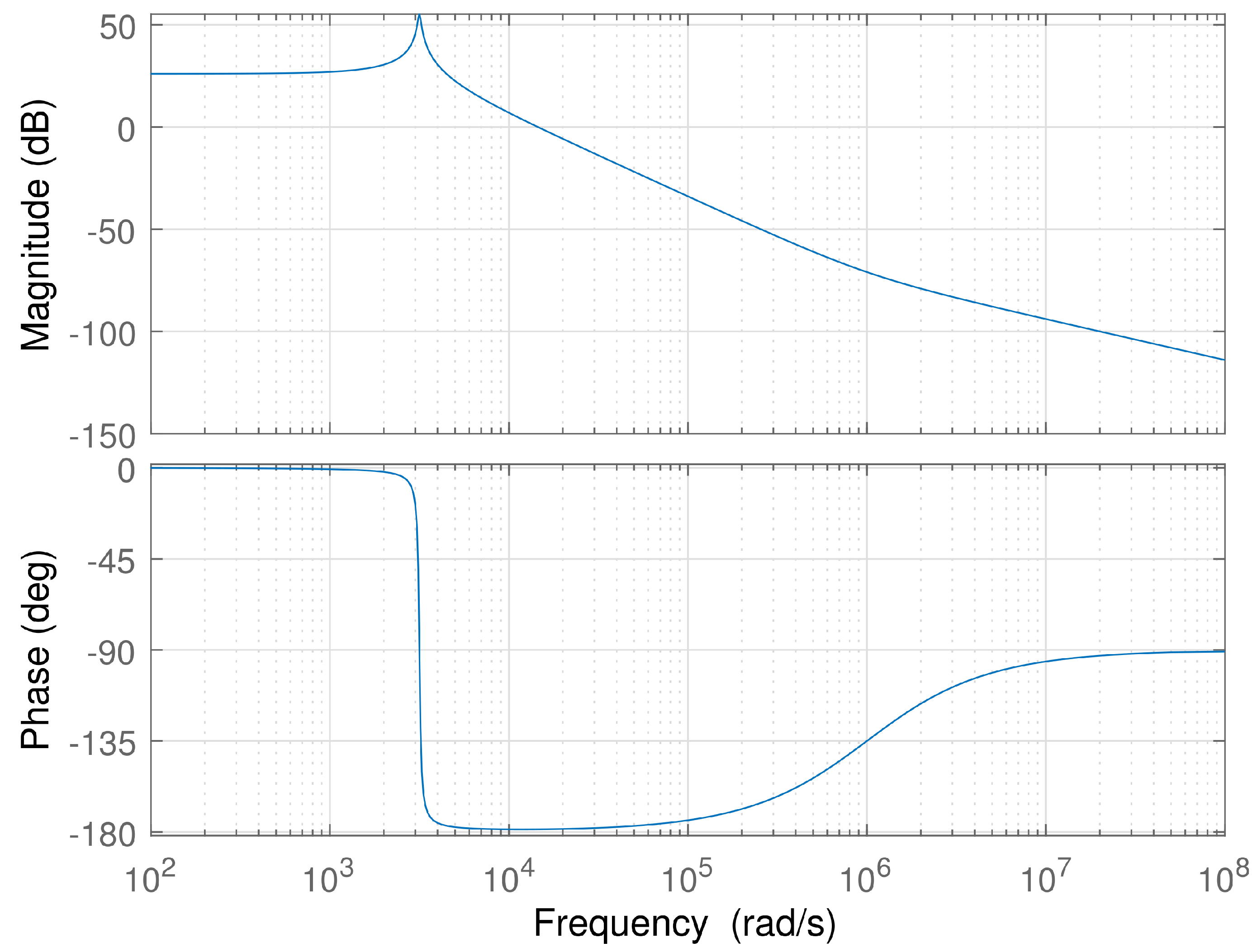
To verify the performance of the proposed algorithm, suppose the non-ideal step-down converter shown in Figure 3, where the parameters of the plant (10) are observed in Table 3. Meanwhile, Figure 8 illustrates the frequency behavior of this example. Analyzing the frequency domain allows one to observe the stability of the system. For this example, the DC–DC converter is stable and has a phase margin of 1.29 degrees in open-loop. In contrast, closed-loop stability cannot be observed using the proposed methodology. This is due to the fact that gains are updated, and therefore, their phase and gain margins are also updated. Hence, a simulation is computed to verify its performance.
This numerical study confirms the efficacy and stability of the proposed ANN-based PID controller, tackling the issues of dynamic adaptation and system uncertainties. Although computational complexity and hardware resource demands are acknowledged as constraints, the numerical simulations illustrate the method’s practical significance for systems necessitating adaptive control. These findings establish a basis for future experimental applications, where optimizations can be investigated to guarantee viability in hardware-limited settings. This step is essential for connecting theoretical contributions with practical applications.
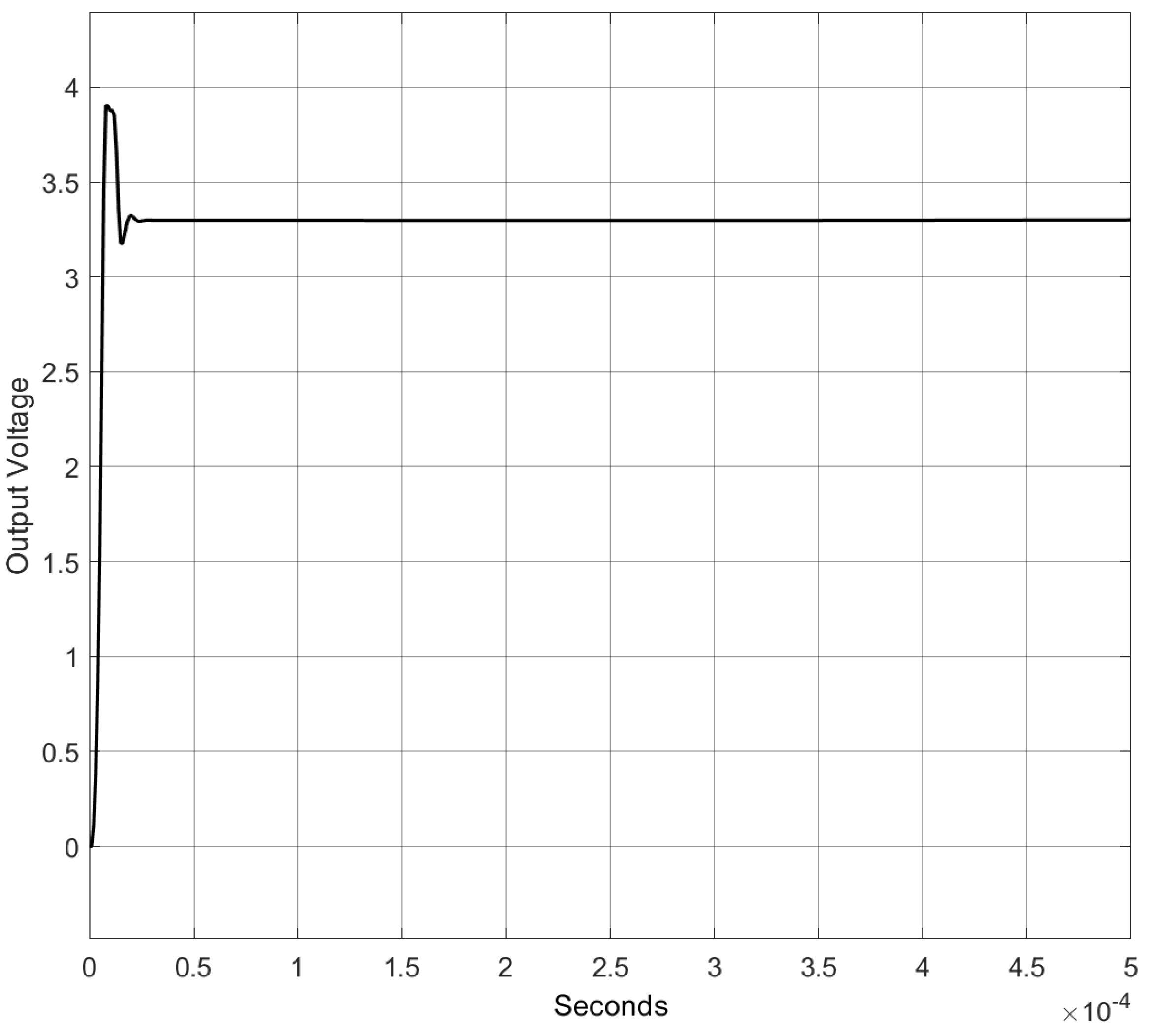
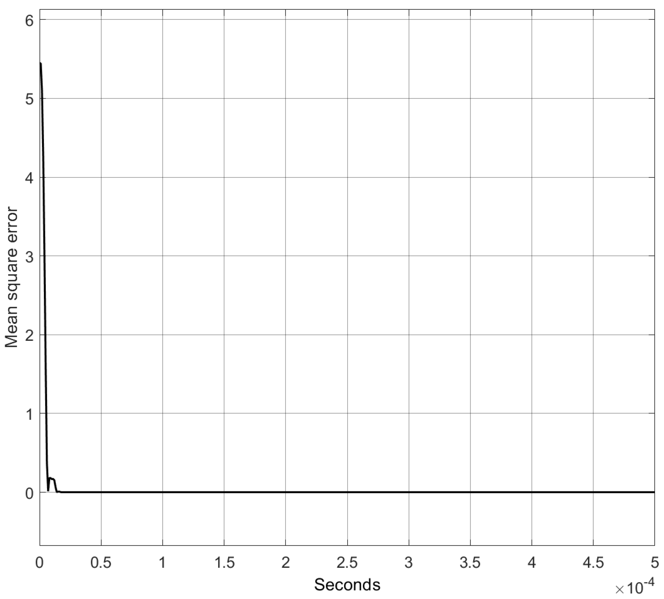
An analysis of the performance of the proposed approach is conducted using numerical simulations. Figure 9 shows the output voltage in the load, where the behavior is relatively smooth and has a maximum overshoot of 15%. In contrast, Figure 10 shows the performance of the mean square error. The results demonstrate that the algorithm effectively and rapidly converges the system’s output voltage to the load, quickly reaching the established reference. However, the system exhibits an overshoot exceeding 0.5 V at a specific moment. This overshoot, along with the system’s convergence speed, can be adjusted by fine-tuning the algorithm’s constant gains to suit the application. In some physical systems, these adjustments may be necessary to address issues related to switching speed and convergence dynamics. Nonetheless, the algorithm offers versatility, allowing for modifications to these parameters as well as the neural network’s learning rate, ensuring the system can be tailored to meet user requirements.

4.1. Comparison

The numerical simulation is compared with existing work in the literature. The comparison is performed against traditional controllers widely used in the industry, specifically
  • Type II controllers [43].
  • Type III controllers [43].
  • PID controllers tuned using the Ziegler–Nichols method [44].
  • The proposed technique.
To simulate real-life situations, various parameters of the plant, such as the input voltage V g , were modified to introduce disturbances and parametric variations. This analysis demonstrates the robustness and adaptability of the proposed ANN-based PID controller under dynamic operating conditions compared to conventional techniques.

4.1.1. Comparison with the Nominal Model

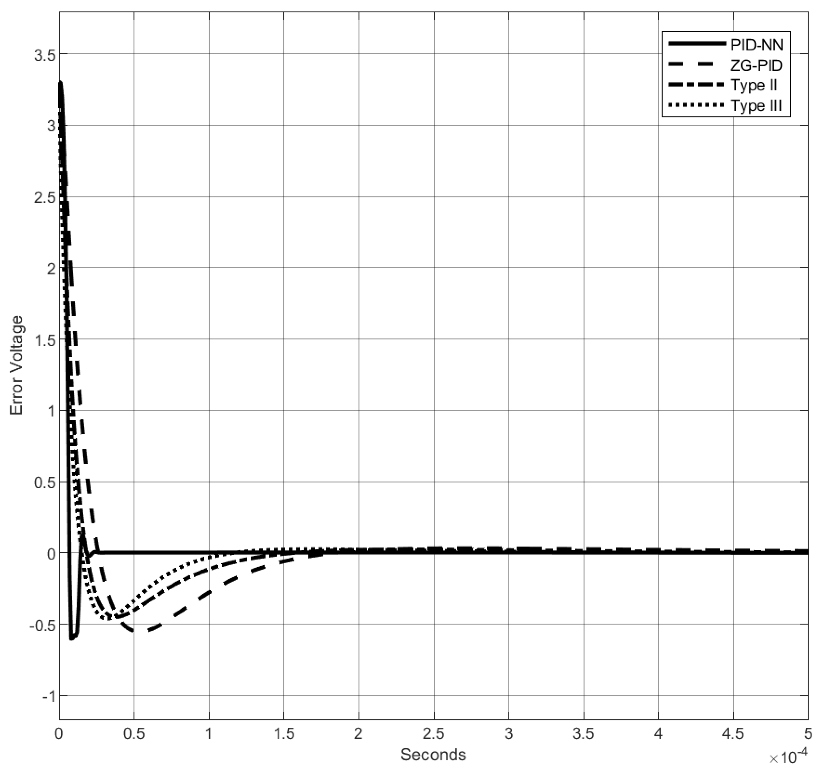
As the name implies, the nominal model is one in which the system’s exact dynamics are known, and no disturbances or other elements are included [45]. Figure 11 shows the comparison of the nominal model and the different control systems to reach the reference, which relates to the behavior of the systems with the various control systems. Moreover, Figure 12 shows how the errors of the different systems converge. These results show that the proposed model has an over-shoot similar to traditional techniques; however, its convergence is faster. To better understand the results obtained, a review of the following parameters for each model is conducted [46]:
  • Delay time ( t d ): the time it takes for a system’s response to initially reach a specified percentage (often 50%) of the final value after a step input is applied.
  • Rise time ( t r ): the time it takes for the system’s response to go from a specified lower percentage (commonly 10%) to a higher percentage (commonly 90%) of the final value.
  • Peak time ( t p ): the time at which the system’s response reaches its maximum value (peak) after a step input is applied.
  • Settling time ( t s ): the time it takes for the system’s response to remain within a specified percentage (e.g., 2% or 5%) of the final value without further deviation.
  • Peak overshoot ( M p ): the maximum deviation of the system’s response above the final value, expressed as a percentage of the final value.
Based on the results of each model, Table 4 summarizes the outcomes for the proposed parameters. The data indicate that the proposed algorithm achieves faster convergence compared to the others; however, it exhibits a slightly higher overshoot. This overshoot can be mitigated by adjusting the algorithm’s constants and the neural network’s learning rate. It is important to note that while these adjustments reduce the overshoot, they may also compromise the convergence speed, potentially increasing the time required to reach the desired results. Consequently, the algorithm is highly versatile and can be tailored to meet the specific requirements of different applications or user preferences. Similarly, Figure 13 provides a graphical representation of the aforementioned results.

4.1.2. Comparison with Variations in the Input

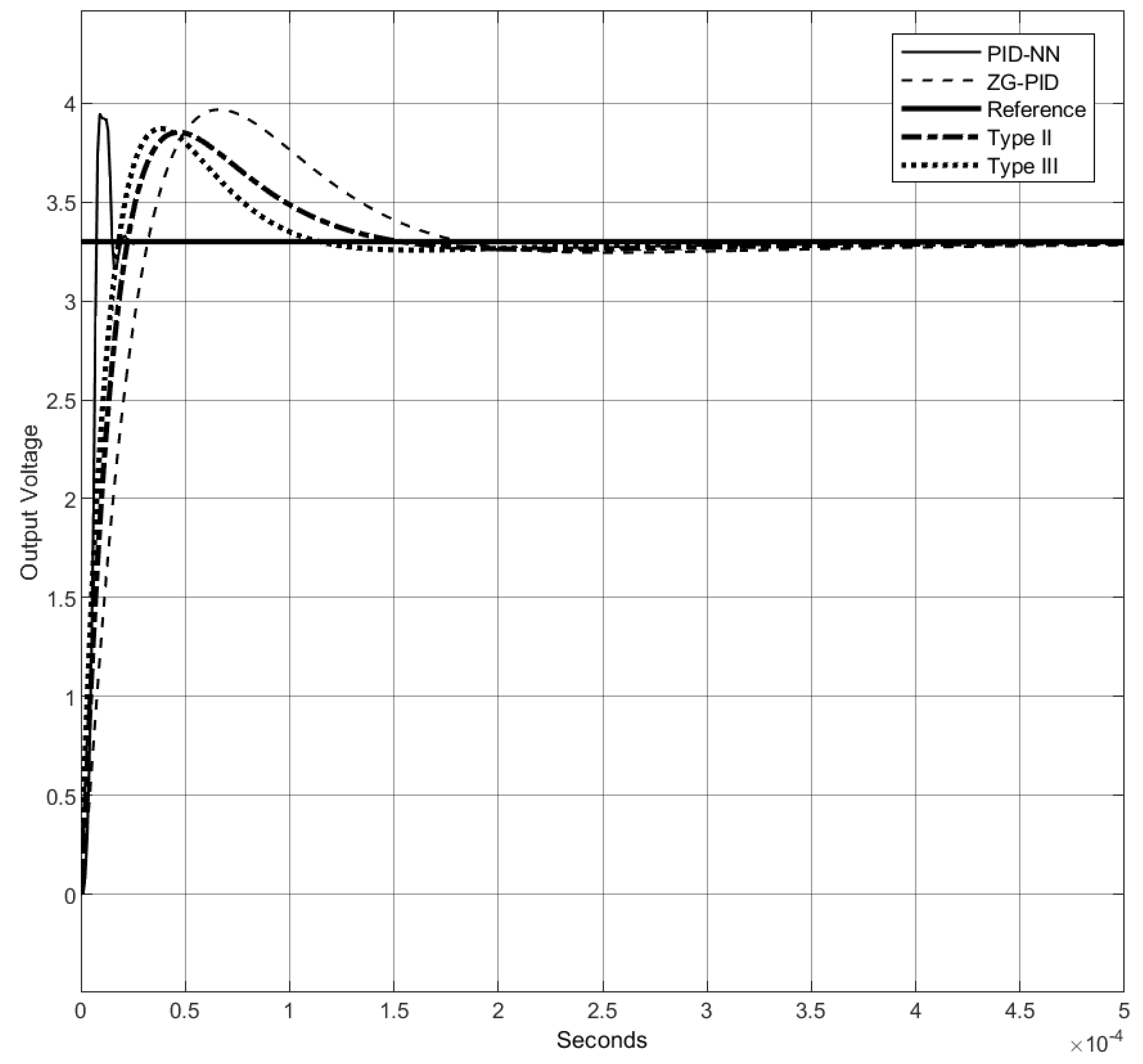
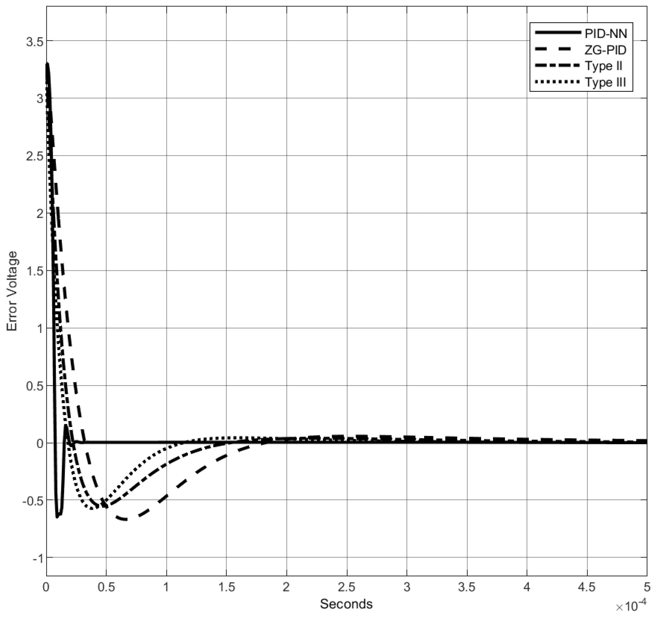
As mentioned earlier, real-life applications often encounter numerous disturbances, one of which, for DC–DC converters, is the variation in input voltage. In this study, the input voltage V g was reduced from 20 V to 10 V, simulating a voltage drop in the converter’s power supply. The results of this scenario are presented in Figure 14 and Figure 15.
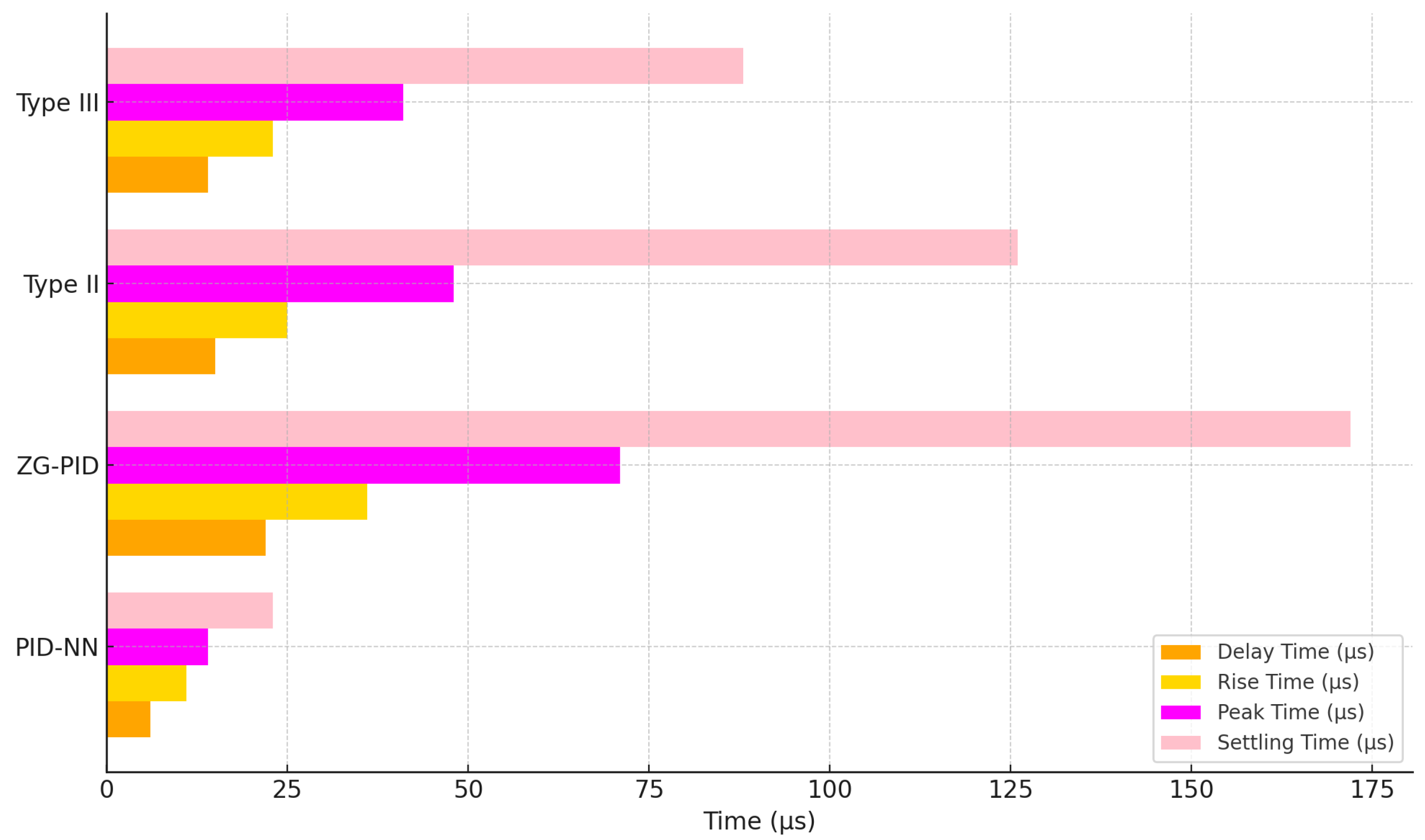
The results demonstrate that the proposed technique maintains behavior similar to the nominal model simulation. In contrast, traditional techniques show poorer performance compared to the previous simulation. Specifically, they exhibit a slower output voltage response and slightly higher overshoot. Additionally, it is evident that the error in some traditional methods does not converge to zero. This occurs because the controllers are tuned with gains optimized for nominal models. When the model parameters change, these control laws lack the robustness required to address such circumstances effectively. Similarly to the nominal model, the same comparative metrics are obtained to evaluate the performance of the different control techniques. Table 5 presents the results of these parameters for the various control laws. Additionally, to better illustrate the results, Figure 16 highlights that the proposed algorithm outperforms the other techniques employing fixed gains.

4.1.3. Comparison with Parametric Variations and a Perturbation in the Input

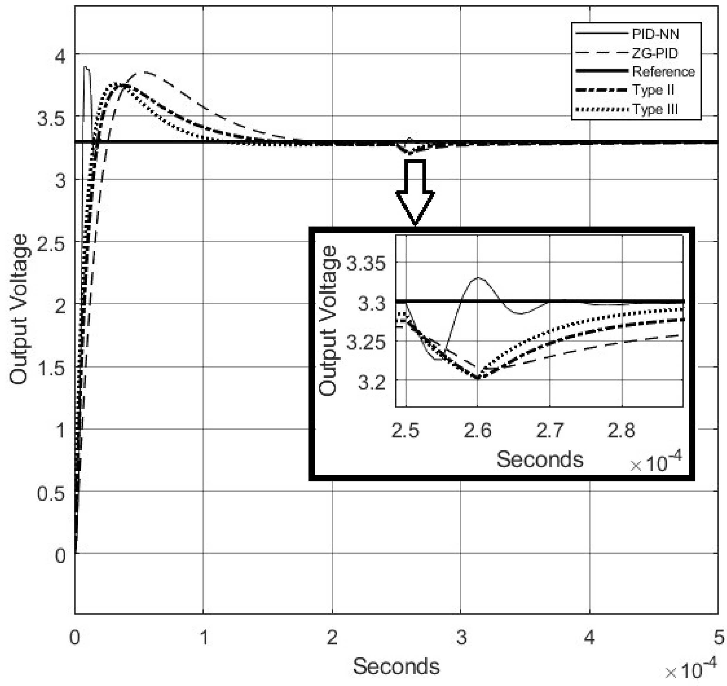
The proposed algorithm is evaluated against conventional methods in this test, where the input voltage variation is maintained, and after a specific period, a disturbance is introduced. Specifically, a disturbance of 0.1 V is applied at the plant’s output for a brief interval, simulating noise in the voltage sensor or an external disturbance affecting the system. Such transients may also arise from factors like load variations, sensor faults, or other similar influences. The effects of this disturbance are illustrated in Figure 17, which compares the system’s response under the proposed algorithm with the responses of various conventional controllers. The results are similar to the previous evaluation, where a variation in input voltage was introduced. Initially, all controllers exhibit comparable behavior. However, once the disturbance is applied, their responses diverge. The proposed controller demonstrates a rapid correction to the disturbance, while the other controllers exhibit an overshoot of up to a 0.1 V drop. This highlights the superior performance of the proposed algorithm in addressing such effects, as its overshoot is significantly smaller compared to the control laws with fixed gains.

5. Conclusions and Future Work

This article explores the control of a synchronous DC–DC converter, addressing the challenges posed by uncertain parameters in passive elements. The proposed methodology leverages a neural network to dynamically adjust the gains of a PID controller, enhancing robustness against unforeseen disturbances. Compared to traditional approaches, such as type II and type III controllers, fixed-gain PID controllers, and other similar techniques, this method exhibits superior performance in maintaining the output voltage at the load. The continuous gain updates provided by the neural network ensure adaptability, while the PID algorithm itself offers better memory efficiency, making it suitable for implementation on low-cost devices compared to other adaptive control techniques. In addition, although this study focuses on a Buck-type converter, the proposed algorithm can be applied to other dynamic systems, particularly other DC–DC converters. However, it is important to note that the algorithm’s constant parameters must be adjusted to achieve optimal results for each specific application.
Moreover, the study achieves its goal of applying a neural network-based model for PID controller tuning, with its stability validated through Lyapunov theory. However, real-time implementation remains an avenue for future work. The practical application was not included due to the scope and length constraints of this article. Ongoing research aims to address these limitations, focusing on a practical model and further reducing computational costs compared to the state-of-the-art and other adaptive algorithms.

Limitations of the Proposed Method

Despite the benefits of the proposed ANN-based PID controller, several limitations must be recognized. The real-time deployment of the artificial neural network necessitates adequate computational resources, potentially restricting its use in low-cost or resource-limited systems. The efficacy of the controller depends on the appropriate selection of parameters δ 1 and δ 2 , necessitating comprehensive empirical tuning across various systems to guarantee convergence and stability. Furthermore, although the proposed method exhibits strong performance amidst disturbances and parameter fluctuations, its efficacy in highly nonlinear or time-varying systems with unmodeled dynamics requires additional validation. Subsequent research will aim to rectify these limitations by improving the computational efficiency of the ANN and formalizing automated parameter tuning techniques to increase applicability across a wider array of dynamic systems.
The computational complexity of the proposed ANN-based PID controller primarily stems from the real-time weight update process, which necessitates gradient computations at every iteration. The implementation of a linear activation function diminishes computational demands; however, resource-limited systems, like inexpensive microcontrollers, may encounter difficulties regarding processing capacity and memory utilization. To mitigate these limitations, one may consider optimizations such as decreasing the number of ANN inputs, precomputing constant elements of the update rule, or employing efficient hardware platforms such as FPGAs and DSPs. These strategies seek to guarantee that the proposed controller is practical for real-world applications while maintaining its adaptability and stability in dynamic conditions. In other words, while the proposed system’s main advantage lies in its adaptability, this comes at the expense of increased computational cost. This is in contrast to control systems with fixed gains, such as Type I, Type II, or PID controllers, regardless of the tuning method used, including popular approaches like Ziegler–Nichols.

Author Contributions

Conceptualization, A.E.R.-M. and J.A.M.-H.; methodology, J.A.M.-H. and V.A.G.-H.; software, V.A.G.-H., F.-R.L.-E. and G.V.-P.; validation, F.-R.L.-E., O.J.S. and G.V.-P.; formal analysis, A.E.R.-M. and J.A.M.-H.; investigation, A.E.R.-M. and V.A.G.-H.; writing—original draft preparation, A.E.R.-M., J.A.M.-H., F.-R.L.-E. and G.V.-P.; writing—review and editing, A.E.R.-M., J.A.M.-H., F.-R.L.-E., O.J.S. and G.V.-P.; supervision, J.A.M.-H.; project administration, J.A.M.-H. All authors have read and agreed to the published version of the manuscript.

Funding

This research was funded by Tecnológico Nacional de México under the program Identificación de aparatos eléctricos y fugas mediante lecturas de consumo de energía utilizando inteligencia artificial como estrategia de ahorro de energía", registrado bajo la clave 19240.24-P. Diseño, Modelado y Control de Sistemas Robóticos: Enfoques Multidisciplinarios desde Métodos Geométricos hasta Inteligencia Artificial", registrado bajo la clave 19602.24-P and the international network Red Internacional de Control y Cómputo Aplicado.

Data Availability Statement

Data are contained within the article.

Conflicts of Interest

The authors declare no conflict of interest.

References

  1. Erickson, R.; Maksimovic, D. Fundamentals of Power Electronics, 2nd ed.; Springer: New York, NY, USA, 2001. [Google Scholar]
  2. De Brito, M.; Canesin, C. Design of a High-Efficiency DC-DC Converter for Solar Panels Using a Synchronous Buck Converter. Int. J. Renew. Energy Res. 2010, 1, 17–23. [Google Scholar]
  3. Rao, K.; Patro, B. Power Electronic Converters for Electric Vehicles: State-of-the-Art and Challenges. J. Power Electron. 2019, 19, 648–665. [Google Scholar]
  4. Mohan, N. Power Electronics: A First Course, 3rd ed.; Wiley: Hoboken, NJ, USA, 2021. [Google Scholar]
  5. Erickson, R.; Maksimović, D. Fundamentals of Power Electronics; Springer International Publishing: Cham, Switzerland, 2020. [Google Scholar] [CrossRef]
  6. Isnaeni, M.; Andromeda, T.; Facta, M.; Warsito, A. A Comparison of Synchronous and Nonsynchronous Boost Converter. Proc. Electr. Eng. Comput. Sci. Inform. 2016, 3, 1135–1142. [Google Scholar] [CrossRef]
  7. Tannir, D.; Wang, Y.; Li, P. Accurate Modeling of Nonideal Low-Power PWM DC-DC Converters Operating in CCM and DCM Using Enhanced Circuit-Averaging Techniques. ACM Trans. Des. Autom. Electron. Syst. 2016, 21, 1–15. [Google Scholar] [CrossRef]
  8. Yue, X.; Wang, X.; Blaabjerg, F. Review of Small-Signal Modeling Methods Including Frequency-Coupling Dynamics of Power Converters. IEEE Trans. Power Electron. 2019, 34, 3313–3328. [Google Scholar] [CrossRef]
  9. Ravi, D.; Ghosh, A. Voltage Mode Control of Buck Converter using Practical PID Controller. In Proceedings of the International Conference on Intelligent Controller and Computing for Smart Power (ICICCSP), Hyderabad, India, 21–23 July 2022; pp. 1–6. [Google Scholar] [CrossRef]
  10. Saurav, S.; Ghosh, A. Design and Analysis of PID, Type II and Type III controllers for Fourth Order Boost Converter. In Proceedings of the 7th International Conference on Electrical Energy Systems (ICEES), Chennai, India, 11–13 February 2021; pp. 323–328. [Google Scholar] [CrossRef]
  11. Ferahtia, S.; Djeroui, A.; Mesbahi, T.; Houari, A.; Zeghlache, S.; Rezk, H.; Paul, T. Optimal Adaptive Gain LQR-Based Energy Management Strategy for Battery–Supercapacitor Hybrid Power System. Energies 2021, 14, 1660. [Google Scholar] [CrossRef]
  12. Mamizadeh, A.; Genc, N.; Rajabioun, R. Optimal Tuning of PI Controller for Boost DC-DC Converters Based on Cuckoo Optimization Algorithm. In Proceedings of the 7th International Conference on Renewable Energy Research and Applications (ICRERA), Paris, France, 14–17 October 2018; pp. 677–680. [Google Scholar] [CrossRef]
  13. Anilkumar, A.; Srikanth, N. Teaching-learning optimization based adaptive fuzzy logic controller for frequency control in an autonomous microgrid. Int. J. Renew. Energy Res. 2017, 7, 1842–1849. [Google Scholar]
  14. Siddique, A.; Munsi, M.; Sarker, S.; Das, S.; Islam, M. Voltage and current control augmentation of islanded microgrid using multifunction model reference modified adaptive PID controller. Int. J. Electr. Power Energy Syst. 2019, 113, 492–501. [Google Scholar] [CrossRef]
  15. Rodríguez-Abreo, O.; Rodríguez-Reséndiz, J.; Fuentes-Silva, C.; Hernández-Alvarado, R.; Falcón, M. Self-Tuning Neural Network PID With Dynamic Response Control. IEEE Access 2021, 9, 65206–65215. [Google Scholar] [CrossRef]
  16. Lee, Y.; Jang, D. Optimization of Neural Network-Based Self-Tuning PID Controllers for Second Order Mechanical Systems. Appl. Sci. 2021, 11, 8002. [Google Scholar] [CrossRef]
  17. Liu, H.; Yu, Q.; Wu, Q. PID Control Model Based on Back Propagation Neural Network Optimized by Adversarial Learning-Based Grey Wolf Optimization. Appl. Sci. 2023, 13, 4767. [Google Scholar] [CrossRef]
  18. Ding, Y.; Cheng, S.; Huang, Y.; Hong, D. Deep PID Neural Network Controller for Precise Temperature Control in Plastic Injection-moulding Heating System. IFAC-PapersOnLine 2022, 55, 114–119. [Google Scholar] [CrossRef]
  19. Ghamari, S.; Khavari, F.; Mollaee, H. Lyapunov-Based Adaptive PID Controller Design for Buck Converter. Soft Comput. 2023, 27, 5741–5750. [Google Scholar] [CrossRef]
  20. Veeramraju, K.; Cardoza, A.; Sarangapani, J.; Kimball, J. Robust Modifications to Model Reference Adaptive Control for Reference Voltage Tracking in a Dual Active Bridge dc-dc Converter. In Proceedings of the IEEE Energy Conversion Congress and Exposition (ECCE), Detroit, MI, USA, 9–13 October 2022; IEEE: Piscataway, NJ, USA, 2022; pp. 1–7. [Google Scholar]
  21. Qureshi, M.; Musumeci, S.; Torelli, F.; Reatti, A.; Mazza, A.; Chicco, G. A novel model reference adaptive control approach investigation for power electronic converter applications. Int. J. Electr. Power Energy Syst. 2024, 156, 109722. [Google Scholar] [CrossRef]
  22. Kim, J.; Choi, H.; Jung, J. MRAC-Based Voltage Controller for Three-Phase CVCF Inverters to Attenuate Parameter Uncertainties Under Critical Load Conditions. IEEE Trans. Power Electron. 2020, 35, 1002–1013. [Google Scholar] [CrossRef]
  23. Wu, J.; Luo, A.; Xu, X.; Shuai, Z.; Yang, X.; Peng, S. MRAC method and its application to single phase shunt active power filter. High Volt. Eng. 2010, 36, 507–512. [Google Scholar]
  24. Ardhenta, L.; Subroto, R. Application of direct MRAC in PI controller for DC-DC boost converter. Int. J. Power Electron. Drive Syst. 2020, 11, 851. [Google Scholar] [CrossRef]
  25. Khanna, R.; Qinhao, Z.; Stanchina, W.; Reed, G.; Mao, Z. Maximum Power Point Tracking Using Model Reference Adaptive Control. IEEE Trans. Power Electron. 2014, 29, 1490–1499. [Google Scholar] [CrossRef]
  26. Mabius, L.; Kalnitsky, K.; Kaufman, H. Model reference adaptive control of electric generating plants. In Proceedings of the 19th IEEE Conference on Decision and Control including the Symposium on Adaptive Processes, Albuquerque, NM, USA, 10–12 December 1980; IEEE: Piscataway, NJ, USA, 1980; pp. 286–291. [Google Scholar]
  27. Saleem, O.; Ahmad, K.; Iqbal, J. Fuzzy-Augmented Model Reference Adaptive PID Control Law Design for Robust Voltage Regulation in DC-DC Buck Converters. Mathematics 2024, 12, 1893. [Google Scholar] [CrossRef]
  28. Ghamari, S.; Gholizadeh, H.; Mollaee, H. Fractional-order fuzzy PID controller design on buck converter with antlion optimization algorithm. IET Control Theory Appl. 2021, 16, 340–352. [Google Scholar] [CrossRef]
  29. Kaplan, O.; Bodur, F. Second-order sliding mode controller design of buck converter with constant power load. Int. J. Control. 2023, 96, 1210–1226. [Google Scholar] [CrossRef]
  30. Nizami, T.; Mahanta, C. An intelligent adaptive control of DC–DC buck converters. J. Frankl. Inst. 2016, 353, 2588–2613. [Google Scholar] [CrossRef]
  31. Saleem, O.; Rizwan, M. Performance optimization of LQR-based PID controller for DC-DC buck converter via iterative-learning-tuning of state-weighting matrix. Int. J. Numer. Model. Electron. Netw. Devices Fields 2019, 32, e2572. [Google Scholar] [CrossRef]
  32. Rigatos, G.; Siano, P.; Sayed-Mouchaweh, M. Adaptive neurofuzzy H-infinity control of DC–DC voltage converters. Neural Comput. Appl. 2020, 32, 2507–2520. [Google Scholar] [CrossRef]
  33. Ghamari, S.; Khavari, F.; Mollaee, H. Adaptive backstepping controller design for DC/DC buck converter optimised by grey wolf algorithm. IET Energy Syst. Integr. 2024, 6, 18–30. [Google Scholar] [CrossRef]
  34. Chouya, A.; Boureguig, K. Adaptive Control with MRAC Regulator for DC-DC Buck Converter. Int. J. Control. Syst. Robot. 2022, 7, 13–26. [Google Scholar]
  35. Surya, S.; Srinivasan, M.; Williamson, S. Modeling of Average Current in Non-Ideal Buck and Synchronous Buck Converters for Low Power Application. Electronics 2021, 10, 2672. [Google Scholar] [CrossRef]
  36. Tan, R.; Hoo, L. DC-DC converter modeling and simulation using state space approach. In Proceedings of the 2015 IEEE Conference on Energy Conversion (CENCON), Johor Bahru, Malaysia, 19–20 October 2015; pp. 42–47. [Google Scholar] [CrossRef]
  37. Fang, J.; Tsai, S.; Yan, J.; Chen, P.; Guo, S. Realization of DC–DC buck converter based on hybrid H2 model following control. IEEE Trans. Ind. Electron. 2021, 69, 1782–1790. [Google Scholar] [CrossRef]
  38. Ji, Y.; Yang, Y.; Zhou, J.; Ding, H.; Guo, X.; Padmanaban, S. Control strategies of mitigating dead-time effect on power converters: An overview. Electronics 2019, 8, 196. [Google Scholar] [CrossRef]
  39. Iqbal, S.; Xin, A.; Jan, M.; Abdelbaky, M.; Rehman, H.; Salman, S.; Aurangzeb, M.; Rizvi, S.; Shah, N. Improvement of power converters performance by an efficient use of dead time compensation technique. Appl. Sci. 2020, 10, 3121. [Google Scholar] [CrossRef]
  40. Haykin, S. Neural Networks and Learning Machines, 3rd ed.; Pearson Education: Upper Saddle River, NJ, USA, 2009. [Google Scholar]
  41. Borase, R.; Maghade, D.; Sondkar, S.; Pawar, S. A review of PID control, tuning methods and applications. Int. J. Dyn. Control. 2021, 9, 818–827. [Google Scholar] [CrossRef]
  42. Lu, Y.; Yu, W.; Wang, J.; Jiang, D.; Li, R. Design of PID Controller Based on ELM and Its Implementation for Buck Converters. Int. J. Control. Autom. Syst. 2021, 19, 2479–2490. [Google Scholar] [CrossRef]
  43. Ghosh, A.; Banerjee, S.; Sarkar, M.; Dutta, P. Design and implementation of type-II and type-III controller for DC–DC switched-mode boost converter by using K-factor approach and optimisation techniques. IET Power Electron. 2016, 9, 938–950. [Google Scholar] [CrossRef]
  44. Ibrahim, O.; Yahaya, N.; Saad, N. Comparative studies of PID controller tuning methods on a DC-DC boost converter. In Proceedings of the 2016 6th International Conference on Intelligent and Advanced Systems (ICIAS), Kuala Lumpur, Malaysia, 15–17 August 2016; pp. 1–5. [Google Scholar] [CrossRef]
  45. Khalil, H. Nonlinear Systems; Prentice-Hall: Upper Saddle River, NJ, USA, 2002. [Google Scholar]
  46. Ogata, K. Modern Control Engineering; Prentice-Hall: Upper Saddle River, NJ, USA, 2020. [Google Scholar]
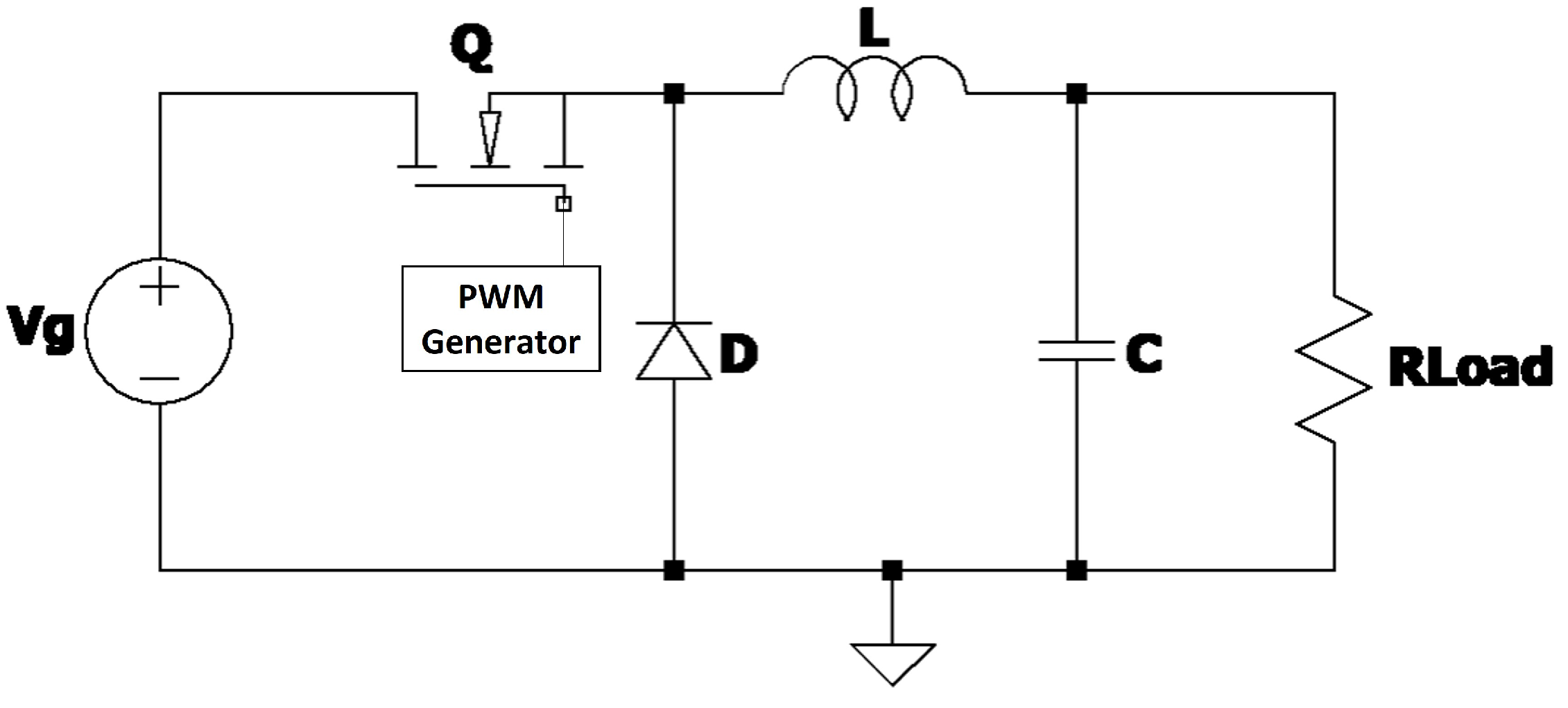
Figure 1. Non-synchronous Buck converter.
Electronics 14 00357 g001
Figure 2. Synchronous step-down converter.
Electronics 14 00357 g002
Figure 3. Synchronous non-ideal Buck converter.
Electronics 14 00357 g003
Figure 4. First stage of the synchronous non-ideal Buck converter.
Electronics 14 00357 g004
Figure 5. Second stage of the synchronous non-ideal Buck converter.
Electronics 14 00357 g005
Figure 6. A single-layer neural network.
Electronics 14 00357 g006
Figure 7. Proposed control block diagram.
Electronics 14 00357 g007
Figure 8. Bode diagram of the non-ideal Buck converter.
Electronics 14 00357 g008
Figure 9. Load output voltage with the proposed controller.
Electronics 14 00357 g009
Figure 10. Mean squared error analysis of output voltage using the proposed algorithm.
Electronics 14 00357 g010
Figure 11. Output voltage comparison across different techniques.
Electronics 14 00357 g011
Figure 12. Comparison of errors across different techniques.
Electronics 14 00357 g012
Figure 13. Comparison of proposed parameters across different control techniques.
Electronics 14 00357 g013
Figure 14. Comparison of output voltage under input voltage variation ( V g = 10 V ).
Electronics 14 00357 g014
Figure 15. Comparison of the error of various techniques with V g = 10 V .
Electronics 14 00357 g015
Figure 16. Comparison of proposed parameters across different control techniques under input variations.
Electronics 14 00357 g016
Figure 17. Comparison of output voltage under disturbances across different techniques.
Electronics 14 00357 g017
Table 1. Definitions and abbreviations.
Term/AbbreviationDefinition/Description
PID ControllerProportional–Integral–Derivative controller; a control loop feedback mechanism.
ANNArtificial Neural Network; a machine learning model that adjusts weights based on input-output data.
Lyapunov stabilityA stability criterion used to prove the convergence of a dynamic system.
e ( n ) Current error signal at time step n.
Δ e ( n ) Change in the error signal: Δ e ( n ) = e ( n ) e ( n 1 ) .
Δ 2 e ( n ) Squared error signal: Δ 2 e ( n ) = e ( n ) 2 e ( n 1 ) + e ( n 2 ) .
k P , k I , k D Gains of the PID controller: proportional, integral, and derivative terms, respectively.
w k ( n ) Neural network weights at time step n.
φ k ( v k ) Activation function; in this work, φ k ( v k ) = v k (linear).
δ 1 , δ 2 Positive parameters of the Lyapunov candidate function used for ANN stability.
γ Learning rate is one such hyper-parameter that defines the adjustment in the weights of our network with respect to the loss gradient descent.
DC–DC converterA power converter that regulates DC voltage by stepping it up or down.
Buck converterA type of DC-DC converter where the output voltage is lower than the input voltage.
Small-signal analysisA method to linearize a system model for analyzing its behavior around an operating point.
Simulation scenarioA computational test used to validate the performance of the proposed control approach.
Table 2. Comparative analysis of the proposed work against the existing state of the art, extracted from [27].
Performance ParameterCOPID [28]HOSMC [29]CNN [30]LQ-PID [31]H-inf [32]Backstepping [33]MRAC [34]
Error minimizationGoodBetterGoodBadGoodFairGood
Asymptotic stabilityYesYesYesYesYesDifficultYes
Control economyFairBadBadBetterFairBadFair
Disturbance rejectionGoodBestBetterBadGoodFairGood
Chattering suppressionGoodFairFairGoodGoodGoodBetter
Mathematical complexityMediumHighHighLowHighHighLow
Computation burdenMediumHighHighLowHighHighLow
Parameter tuning neededHighMediumHighLowHighHighLow
Table 3. Parameters of the non-ideal Buck converter.
ElementDescriptionValueUnit
V g Input voltage20V
CCapacitance0.1mF
LInductance1mH
R C Internal resistance0.01 Ω
R L Internal resistance0.1 Ω
R L o Load10 Ω
rDesired output voltage3.3V
Table 4. Performance metrics comparison using the nominal model.
MethodDelay TimeRise TimePeak TimeSettling TimePeak Overshoot
PID-NN μ s10  μ s13.5  μ s22  μ s0.58 V
ZG-PID16  μ s26  μ s51  μ s125  μ s0.52 V
Type II13  μ s21  μ s37  μ s88  μ s0.47 V
Type III11  μ s19  μ s30  μ s80  μ s0.48 V
Table 5. Comparison of performance metrics using the nominal model under input variations.
MethodDelay TimeRise TimePeak TimeSettling TimePeak Overshoot
PID-NN μ s11  μ s14  μ s23  μ s0.59 V
ZG-PID22  μ s36  μ s71  μ s172  μ s0.61 V
Type II15  μ s25  μ s48  μ s126  μ s0.51 V
Type III14  μ s23  μ s41  μ s88  μ s0.52 V
Disclaimer/Publisher’s Note: The statements, opinions and data contained in all publications are solely those of the individual author(s) and contributor(s) and not of MDPI and/or the editor(s). MDPI and/or the editor(s) disclaim responsibility for any injury to people or property resulting from any ideas, methods, instructions or products referred to in the content.