Abstract
Reconfigurable intelligent surfaces (RISs), recognized as one of the most promising key technologies for sixth-generation (6G) mobile communications, are characterized by their minimal energy expenditure, cost-effectiveness, and straightforward implementation. In this study, we develop a novel communication channel model that integrates RIS-enabled base stations with unmanned ground vehicles. To enhance the system’s adaptability, we implement a fluid antenna system (FAS) at the unmanned ground vehicle (UGV) terminal. This innovative model demonstrates exceptional versatility across various wireless communication scenarios through the strategic adjustment of active ports. The inherent dynamic reconfigurability of the FAS provides superior flexibility and adaptability in air-to-ground communication environments. In the paper, we derive and study key performance characteristics like the autocorrelation function (ACF), validating the model’s effectiveness. The results demonstrate that the RIS-FAS collaborative scheme significantly enhances channel reliability while effectively addressing critical challenges in 6G networks, including signal blockage and spatial constraints in mobile terminals.
1. Introduction
1.1. Background
In recent years, air–ground communication has increasingly become a crucial and inseparable key component of the sixth-generation (6G) mobile network [1,2,3]. The advent of 6G signifies a revolutionary leap in wireless communication, characterized by exceptionally fast data speeds, extremely low latency, ultra-reliable connectivity, and energy efficiency [4,5,6].
However, in communication-dense areas, signal transmission between base stations and ground receivers (GRs) often faces significant challenges due to obstructions such as tall buildings and trees. To overcome this technical bottleneck, reconfigurable intelligent surfaces (RISs) and fluid antenna systems (FASs), as two breakthrough technologies, provide innovative solutions for 6G communications from the network side and the terminal side, respectively [7].
Composed of programmable meta-atoms, RISs can dynamically manipulate the propagation of electromagnetic waves to mitigate signal blockage in urban environments, and they exhibit great potential particularly in high-frequency bands like millimeter wave and terahertz [8]. At the same time, FASs break through the spatial limitations on the terminal side by means of reconfigurable radiating elements that adaptively switch receiving positions within a limited space. This dynamic reconfigurability enables FASs to achieve multi-antenna diversity gains comparable to those of traditional MIMO systems within a limited space, addressing the challenge of it being difficult to deploy high-performance antenna arrays in space-constrained mobile devices. The collaborative application of RISs and FASs provides an end-to-end optimization solution for high-reliability and high-capacity communication in 6G networks and has become a research hotspot in both academia and industry.
There are significant differences in channel modeling research for different frequency bands. For example, in the sub-6 GHz channel, its characteristics mainly manifest as strong diffraction and scattering capabilities and strong non-line-of-sight (NLoS) propagation capabilities. In the millimeter-wave frequency band, due to the short wavelength, the path loss is large, and the diffraction capability is extremely weak, so it relies on Los paths or reflection paths assisted by RISs. In the terahertz frequency band, the coverage range is limited by challenges such as extremely high path loss, molecular absorption, and extremely narrow coherence bandwidth. The channel characteristics of different frequency bands vary greatly, so different theories and methods should be adopted in modeling. In this work, we choose 5 GHz for modeling because of its relatively balanced propagation characteristics in urban environments. Its strong diffraction ability and non-line-of-sight (NLoS) propagation capability have been well documented in prior research. This frequency band has been studied extensively, providing a solid foundation for validating our 3D physics-based RIS-FAS channel model.
However, channel behavior exhibits significant variations across different frequency bands. If the frequency goes to a higher band, for example, to the millimeter-wave or terahertz frequency band, path loss increases sharply, and diffraction becomes weaker. Molecular absorption and narrow coherence bandwidth in terahertz bands bring more complexities. These differences mean that the corresponding channel modeling methods will no longer be applicable, and we need distinct modeling approaches.
1.2. Related Works
Studies have shown that RISs can significantly improve the spectral efficiency and energy efficiency of communication systems through intelligent reflection and beamforming [9]. For example, Reference [10] first proposed an application framework of an RIS in 6G networks, elaborating on its ability to optimize channel quality by dynamically adjusting the phase and amplitude of incident signals. Reference [11] further studied the performance of an RIS in multi-user scenarios and demonstrated its advantages in enhancing coverage and reducing interference.
Currently, channel modeling for RIS-aided communications mainly faces two major challenges: near-field effects and adaptability to dynamic environments. For RIS modeling, Reference [12] proposes a 3D physics-based end-to-end model for double-RIS-assisted non-stationary UAV-to-ground communications, capturing near-field effects and dynamic propagation characteristics. Reference [13] constructs a 3D geometry-based stochastic channel model for intelligent reflecting surface-assisted UAV MIMO communications, providing a basis for analyzing spatial correlation. Reference [14] focuses on air-to-ground channels of large-scale RISs, conducting in-depth near-field modeling and analysis and revealing the impact of RIS array scale on channel characteristics. Reference [15] establishes a channel model for RIS-assisted millimeter-wave communication systems based on physical layer principles, considering the unique features of beam propagation.
In addition, the combination of RISs with other advanced communication technologies has also become a research focus [16]. Reference [17] studied the RIS-assisted wireless power transfer (WPT) system and showcased its potential in improving energy efficiency. In the field of non-orthogonal multiple access (NOMA), the application of an RIS in active monitoring systems has also been widely studied. Reference [18] demonstrated its unique advantages in environmental perception and dynamic signal regulation. Reference [19] explored the application of an RIS in mobile edge computing (MEC) systems. By jointly optimizing computation offloading and reflection coefficients, it significantly reduced the task processing delay.
Although the RIS, with its ability to dynamically regulate signal characteristics and flexible deployment capabilities, has provided an innovative solution to the communication problems between base stations and ground receivers, effectively alleviating the signal transmission bottleneck caused by obstacles [20], new challenges still remain at the terminal device level [21,22]. Take unmanned ground vehicles, which have extremely high requirements for mobility and integration, as an example. The limited physical space of such devices makes it difficult for traditional antenna deployment to meet the requirements of 6G communication for multi-antenna diversity gain [23]. Even with the help of RISs to optimize the transmission path, the signal reception and processing capabilities on the terminal side still restrict the overall communication performance.
Against this backdrop, the fluid antenna system, as a revolutionary terminal antenna technology, has brought a new breakthrough direction for the communication of unmanned ground vehicles. Through antenna designs based on liquid or reconfigurable pixels, the FAS allows the antenna to freely switch to the optimal signal reception position within a limited space, breaking free from the dependence of traditional antennas on physical space. This reconfigurable feature forms a natural complement to the RIS. The RIS is responsible for reconstructing the signal propagation path at the macro level to avoid obstacle interference, while the FAS starts from the interior of the terminal device, utilizing the degree of freedom (DoF) in space to maximize the signal reception efficiency, enabling efficient diversity reception even in a narrow space [24,25].
The basic working principle of the fluid antenna system is to evenly distribute multiple ports within a linear spatial domain. The antenna can dynamically switch its position and selectively activate single or multiple ports to achieve communication purposes. Thanks to the flexibility of reconfigurable antennas, the FAS effectively utilizes the spatial degrees of freedom (DoFs) to obtain sufficient diversity gain, significantly enhancing communication performance even in a very small space.
Compared to traditional multi-antenna systems (e.g., MIMO), the FAS offers distinct advantages. In conventional designs, antenna spacing typically requires at least half a wavelength to minimize mutual coupling effects, which poses a significant challenge for space-constrained mobile devices such as smartphones and tablets [26]. This requirement not only occupies valuable space but also increases system complexity. The FAS overcomes this limitation by leveraging the dynamic reconfigurability of antennas, enabling high-performance communication within extremely confined spaces, thereby enhancing network capacity and reliability. For the compatibility design of compact devices, the FAS realizes the equivalent multi-antenna function in limited spaces such as UGV antenna compartments through a dynamic port switching mechanism.
Current FAS implementations primarily employ two distinct approaches to achieve antenna reconfigurability within constrained spaces. One is the liquid metal-based scheme, which utilizes gallium-based alloys or ionic solutions to dynamically reconfigure the antenna morphology through electrowetting or microfluidic pump mechanisms. Experimental data confirm that this scheme can achieve sub-wavelength port spacing () and millisecond-level switching speed. The other is based on pixelated reconfigurable surface technology, which uses PIN diodes or RF-MEMS switches to dynamically reorganize antenna patches. With the help of PIN diode or RF-MEMS switch arrays, it can achieve an extremely dense port spacing of /20~/30. In this paper, the pixelated reconfigurable surface approach is selected as the preferred implementation for the FAS design, primarily because of its high compatibility with RIS control mechanisms and its ability to meet the size and dynamic requirements of UGV terminals. Although the liquid metal scheme has potential in low-frequency scenarios, it is necessary to further solve the problems of high-frequency loss and mechanical reliability.
The existing literature has extensively studied the advantages of the fluid antenna system, emphasizing its potential in various applications. For example, the authors of Reference [27] studied its characteristic of a software-controlled, flexible, and variable nature, as well as its ability to unleash diversity within the small space of mobile devices. The authors of References [28,29] comprehensively studied its feasibility and performance advantages. Particularly in supporting large-scale device connectivity, they confirmed its ability to enhance network capacity and reliability.
The internal fluid movements of FASs play a vital role in channel stabilization. By enabling the real-time switching of active antenna ports within a compact spatial domain, the FAS continuously selects the optimal port with the strongest signal path, mitigating fading induced by obstructions or mobility. The internal fluid movements of the antenna also enhance channel stability by reducing spatial correlation between ports, minimizing the simultaneous fading across ports and enhancing diversity gain.
For FAS modeling, Reference [30] conducts in-depth research on the outage probability of and diversity gain in fluid antenna systems, proposing a channel model suitable for compact spaces. Reference [31] derives closed-form expressions for spatial correlation parameters, providing a tool for analyzing correlations between FAS ports. Reference [32] proposes a new analytical approximation method for fluid antenna system channels, further improving the channel description of FASs.
In recent years, the collaborative application of RISs and FASs has gradually become a research frontier. Current studies primarily revolve around system modeling, performance analysis, and optimization design. Reference [33] proposed a comprehensive analytical framework for FAS-RIS systems, established a mathematical model, and derived closed-form expressions for outage probability, laying the theoretical foundation for subsequent research. This study particularly focused on the spatial correlation between FAS ports and introduced a block diagonal matrix approximation model to simplify the analysis.
In terms of performance analysis, Reference [34] conducted a thorough modeling and analysis of FAS-RIS communication systems, with a focus on system capacity and outage performance under different channel conditions. This research demonstrated that, compared to traditional RIS-assisted systems, FAS-RIS systems can provide additional diversity gain in space-constrained scenarios. Reference [35] further proposed a block correlation model, conducting an in-depth analysis of the impact of FAS port correlation on system performance. It was found that moderate correlation actually helps reduce outage probability. In the area of optimization design, Reference [36] analyzed the outage probability for FAS-RIS (Active reconfigurable intelligent surface) systems and proposed a joint optimization scheme. This study pointed out that, even under partial CSI conditions, the joint optimization of intelligent reflecting surface configuration and fluid antenna port selection can significantly improve system throughput. Notably, these studies collectively indicate that the performance advantages of FAS-RIS systems are particularly prominent in millimeter-wave and terahertz frequency bands, offering a novel solution for 6G high-frequency communications.
However, existing research still faces several challenges. While both RISs and FASs have been widely investigated as key technologies for communication performance enhancement, their joint optimization remain unexplored. Current research on RIS-assisted channel models predominantly focuses on single-technology optimization. It often simplifies propagation paths as either line-of-sight or non-line-of-sight [37] while neglecting the spatial diversity gains achievable through FAS integration. Research related to FASs has mostly been conducted independently as well, lacking in-depth integration with RIS technology [38,39]. Meanwhile, in dynamic environments, a systematic framework for modeling time-varying channel characteristics and jointly optimizing key parameters in RIS-FAS has not yet been established. Although Reference [16] emphasized that deep reinforcement learning could be a promising solution for real-time optimization in non-stationary RIS-FAS, challenges in computational complexity and channel feedback latency remain. These critical issues must be addressed to achieve genuine synergy between RIS and FAS technologies.
1.3. Main Contributions
This research presents an integrated framework combining RISs and FASs to develop an advanced three-dimensional channel model for air–ground communication.
The main contributions are summarized as follows:
- We established a novel 3D channel model that integrates RIS-enabled base stations with unmanned ground vehicles equipped with an FAS. This combination makes full use of the advantages of the two technologies: the reconfigurable intelligent surface enhances the signal coverage and quality, while the fluid antenna system provides adaptive antenna configurations for dynamic environments.
- We derived the complex channel impulse responses (CIRs) of the propagation links in the communication system consisting of a base station equipped with an RIS and a UGV equipped with a fluid antenna system. In the study, we identified and established two path propagation mechanisms, namely the reflection path by the reconfigurable intelligent surface and the non-line-of-sight (NLoS) path formed by the reflections of scatterers. A direct line-of-sight is not included in these paths. Meanwhile, when deriving the expression of the time-varying channel impulse response, the Rician factor K was introduced to dynamically adjust the weight of the RIS reflection and scatterer cluster reflection components.
- Based on temporal correlation, we calculated the proposed model’s statistical characteristics, including key performance metrics such as the autocorrelation function (ACF). Through a comprehensive analysis of these indicators, we demonstrate that the RIS-assisted FAS exhibits superior flexibility and adaptability compared to standalone RISs or FASs.
The above systems provide technical support to propel the rapid advancement of China’s 6G mobile communication industry. It is worth noting that in 6G air-to-ground communication scenarios, signal transmission between base stations and unmanned ground vehicles not only faces blockage issues caused by obstacles such as skyscrapers and trees but is also constrained by the spatial limitations of ground terminals. Therefore, proposing a channel model that accurately reflects the physical characteristics of RISs and the dynamic reconfigurability of FASs is of utmost importance. Future work will focus on hardware prototype design and field trials to validate these gains in real-world environments.
The rest of this paper is structured as follows: Section 2 introduces the 3D system model for RIS-FAS-assisted BS-UGV communications, including geometric configurations and channel modeling assumptions. Section 3 derives the complex channel impulse responses and analyzes key propagation statistics such as autocorrelation functions. Section 4 investigates the key propagation statistics of the proposed channel model. In Section 5, we validate the model through numerical simulations and discuss performance insights. Finally, Section 6 concludes this work and outlines future research directions.
2. System Model
In dense urban wireless communication scenarios, the direct transmission path between base stations and ground users is often blocked by urban infrastructure, leading to degraded signal reliability. Reconfigurable intelligent surface technology can be deployed to establish indirect, yet stable, transmission routes, enhancing cost-effectiveness, power utilization, and bandwidth efficiency.
Meanwhile, to accurately capture the complex physical characteristics between base stations and ground vehicles in urban environments, the proposed channel model incorporates scattering clusters. The -th () scattering cluster contains scatterers. Due to space limitations, only the -th scattering cluster is depicted in Figure 1. In addition, the positions of the scatterers are not fixed. The arrival azimuth and elevation angles of NLoS propagation links are randomly generated through a Gaussian distribution function, thus determining the specific positions of the scatterers.
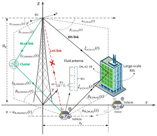
Figure 1.
A 3D channel model for RIS-FAS-assisted BS-UGV communication.
We propose a three-dimensional channel model for base-station-to-unmanned-ground-vehicle communication, where a linear fluid antenna system is equipped on the unmanned ground vehicle side. It has a length of and ports. The distance between adjacent ports can be expressed as
The base station incorporates a -element uniform linear array (ULA) made up of omni-directional radiating elements. For each -th antenna element, where , the relative position vector between the array’s central reference point and the antenna is given by
with the spatial coefficient determining the element positioning, the array’s geometric configuration being characterized by the azimuthal angle and zenith angle , and the parameter denoting the uniform inter-element spacing within the ULA setup.
The position vectors from the coordinate system’s origin to the geometric centers of the base station and mobile receiver antenna arrays can be mathematically expressed as follows
Within the global coordinate framework, the center position of the reconfigurable intelligent surface is represented by the vector . For each individual RIS element located at coordinates , where , and , its spatial displacement relative to the origin can be mathematically described as follows
The practical implementation of the RIS in this study is based on state-of-the-art tunable metamaterials. These metamaterials have been widely validated in recent research. They can achieve 1-bit to 4-bit phase control in the millimeter-wave band, with a reflection efficiency exceeding 90%. Their reconfiguration latency is at the sub-millisecond level, reaching 500 microseconds. In terms of array design, we adopt a 256-element RIS configuration. Experimental data from similar configurations [17] show that such arrays can achieve an energy efficiency of 92%, meeting the low-power requirements. Regarding the control mechanism, our model uses hierarchical beam codebooks to reduce the complexity of real-time optimization.
In practical communication systems, the role of the RIS is to reflect the received signals toward the target user (e.g., an unmanned ground vehicle), while the antenna configuration at the receiver further influences the channel characteristics. Therefore, when defining the channel matrix, it is necessary to consider the number of active ports and their spatial distribution in the fluid antenna system at the receiver.
Specifically, is a variable value because in actual fluid antenna communication scenarios, one or multiple ports may be used for communication, i.e., active ports. In this paper, we introduce the general form of the channel matrix applicable to the FAS and use to represent the number of active ports. Therefore, the set of can be expressed as follows:
where denotes the set of ports at the MU side. Then the position of the -th can be expressed as
3. Complex CIRs of the Proposed Channel Model
Assuming that there is no direct link between the base station (BS) and the unmanned ground vehicle (UGV), the reconfigurable intelligent surface becomes crucial for restoring the communication link. In the developed channel model, the signal transmitted from the base station arrives at the unmanned vehicle through two distinct links: (i) the RIS link, where signals first arrive at the RIS array, undergo programmable amplitude and phase adjustments by the RIS, and are subsequently redirected to the unmanned vehicle, i.e., BS→RIS→UGV link; (ii) the non-line-of-sight path, where the signal is reflected by scatterers close to the base station before ultimately propagating to the unmanned vehicle, i.e., BS→scatterers→UGV link.
Since the RIS is typically installed close to the base station and at an elevated position above the ground, the channel between the BS and the RIS is considered a pure LoS link. The channel can be mathematically expressed as follows:
where is the path loss factor, and represents the LoS channel vector.
Considering that the distance between the RIS and the user may be large and the user’s height is limited, the channel between the RIS and the UGV tends to exhibit NLoS characteristics. Therefore, the Rician channel model is adopted for its description. The channel from the RIS to the -th port of the user can be expressed as follows:
where represents the path loss coefficient, and is the Rician factor. The LoS component characterizes the deterministic propagation characteristics, while the NLoS component represents the Rayleigh fading component. The elements are identically and independently distributed circularly symmetric complex Gaussian variables, exhibiting zero-mean characteristics with unit variance.
The propagation link between the transmitter and the receiver is jointly composed of the airborne RIS array component and the scatterers in the NLoS component. It is assumed that the RIS and NLoS propagation links operate independently. Therefore, we have
Here, represents the path delay. This paper adopts a spatial scattering channel modeling approach, where each array element is modeled as an independent reflector. Consequently, the total channel matrix results from the superposition of all transmission paths.
The time-varying channel matrix , with dimensions , comprehensively characterizes the system’s propagation properties through its elements , which represent the complex impulse responses for each transmitter–receiver path. Specifically, these response functions are mathematically expressed as follows:
in which represents the path loss, with being the Rician factor, defined as the percentage of RIS links to NLoS links.
When , the RIS-reflected path dominates the channel, indicating strong directivity with minimal scattering effects. When , the NLoS scatterer cluster contributions become dominant, which is typical of rich scattering environments. The weights and are derived from the properties of the Rician distribution, ensuring the total power is normalized. The Rician factor plays a vital role in governing the temporal coherence of the channel. When the value of is relatively high, the RIS-reflected path dominates, thus significantly slowing down the decay rate of the ACF. Conversely, in a scattering environment rich in multipaths ), the channel approaches the Rayleigh fading model, resulting in a faster decay of temporal correlation.
are the path delays of the two components, respectively, and c represents the speed of light.
Regarding the propagation components, the real-time propagation distances from the midpoints of the uniform linear arrays (ULAs) of the transmitter and the receiver to the midpoint of the reflecting surface can be formulated as follows:
The Frobenius norm operator, denoted by , is employed throughout these calculations. For the NLoS propagation channel, the dynamic spatial separation between the base station and ground receiver array centroids relative to the scattering cluster center evolves temporally according to the following:
Consequently, the instantaneous path lengths between individual transceiver elements and RIS units can be mathematically formulated. Specifically, for the transmitting antenna element and receiving port , their respective distances to the -th reflecting element are expressed through the following geometric relationships:
3.1. Aerial RIS Array Component
For the aerial RIS subsystem, we mathematically characterize the wireless channel response between specific transceiver components. The complex channel gain linking transmitter antenna element with receiver port through RIS reflection is given by the following:
Here, represents the time-varying amplitude modulation coefficient of each RIS element, and captures the instantaneous phase shift for the -th unit cell. In this system model, it is assumed that each unit within the airborne reconfigurable surface possesses both amplitude reflection characteristics and phase adjustment capabilities, among which the phase adjustment capabilities exhibit extremely high resolution. The wavelength is denoted by , and .
Moreover, serves as the normalization factor for the RIS link to ensure has unit power, which can be defined as
where denotes the expectation operation, which applies to the reflection phase in the RIS propagation links.
The system’s geometric configuration, which consists of the BS, the RIS, and GRV, determines the fundamental channel parameters such as propagation delays, angular components, and path distances. By conducting a spatiotemporal correlation analysis of these network elements, we can establish a connection between the system’s state and the channel behavior. Specifically, we can derive the time-evolving channel characteristics by incorporating several key factors: the temporal evolution factor , the mobility vectors (including direction and speed), and the initial transceiver positioning parameters.
When the near-field propagation assumptions are applied, each RIS unit cell shows unique angular characteristics. As a result, the azimuth angle of departure (AAoD) and elevation angle of departure (EAoD) of the BS to the -th RIS element can be mathematically described as follows:
The azimuth angle of arrival (AAoA) and elevation angle of departure (EAoD) for the signal from the (m,n)-th element of the RIS to the ground robotic vehicle (GRV) can be formulated as follows:
3.2. NLoS Component
For the NLoS propagation link via the cluster, the channel coefficient can be described as
In the scattering environment, parameter denotes the number of non-line-of-sight propagation paths within each cluster. Following conventional modeling approaches, we consider the asymptotic case where becomes unbounded ( to ). The phase component for each propagation path follows a uniform distribution across the interval , expressed as . These modeling parameters, including initial time delays, propagation distances, and angular characteristics, may be derived through either statistical modeling approaches or empirical measurements. Within any given scattering cluster, all scatterers are modeled with nearly identical initial distances relative to the ground receiver’s antenna array center, despite their angular variations.
and are the time-varying propagation distances from the center of the base station transmitting antenna array and the center of the UGV receiving antenna array to that of the cluster, which can be derived, respectively, by taking the magnitude of and .
and represent the distances from the centers of the base station and unmanned ground vehicle antenna arrays to the center of the cluster at the start of the motion, specifically when . Each of these distances can be calculated separately
where , , and represent the cluster’s coordinates along the -, -, and -axes, respectively.
In the initial stage of motion, and denote the azimuth angle of departure (AAoD) and elevation angle of departure (EAoD), respectively, for the wave reaching the -th scatterer within the cluster from the base station. Meanwhile, and represent the AAoA and EAoA, respectively, for the wave scattered from the cluster.
The time-varying EAoD and AAoD of the wave from the BS to the -th scatterer within the cluster can be expressed as follows:
The time-varying AAoA and EAoA of the wave traveling from the -th scatterer to the unmanned ground vehicle are given by the following:
In this study, the von Mises distribution is introduced to determine each scatterer’s position, offering a robust approach to modeling their spatial arrangement.
It can be mathematically expressed as
where denotes the environment factor. stands for the mean values of , and represents a modified Bessel function of order 0.
4. The Propagation Statistics of the Proposed Channel Model
Our analysis results show that the channel impulse response exhibits multidimensional correlations and is simultaneously affected by temporal, spatial, and spectral variations. Notably, when comparing different spatial locations or frequency components at the same time point, significant differences in channel characteristics will occur. This phenomenon is attributed to three key factors:
- (1)
- The high-density unit configuration of the RIS;
- (2)
- The rapid movement pattern of UGVs;
- (3)
- The broadband characteristics of signal propagation.
The combined effect of these factors leads to obvious non-stationarity in the communication channel between the BS and the UGV, and this non-stationarity is manifested in the three fundamental domains of space, time, and frequency. Therefore, in order to accurately describe these dynamic propagation characteristics, we must establish a comprehensive parameterization framework that explicitly takes into account three factors: spatial correlation, temporal variations, and frequency-selective effects. The formula can be expressed as follows:
When the conditions and are imposed, resulting in , Equation (24) serves as a means to define the autocorrelation functions (ACFs) of the RIS/NLoS propagation channels across various time points. These ACFs effectively capture the time-dependent correlation properties inherent in the proposed channel model. Specifically, the term represents the complex-valued channel impulse response for the signal traveling from rom the -th antenna element of the BS array to the -th port of the FAS equipped on the UGV. The symbol signifies the operation of calculating the statistical mean, while indicates the process of taking the complex conjugate. Moreover, ) quantifies the correlation between different RIS-mediated propagation paths, and its mathematical formulation can be derived as follows:
The autocorrelation function (ACF) between distinct NLoS components passing through a cluster is denoted by . In this study, it is hypothesized that the quantity of scatterers within the cluster approaches infinity, symbolized as . The summations involving an infinite number of scatterers are substituted with integrations over and . As a result, we have
Within this propagation environment, incident rays from individual scattering clusters exhibit constrained angular distributions. To accurately characterize these directional properties, we employ two statistical models: a truncated Gaussian distribution and a Laplace distribution for modeling the initial angular spread. The joint probability density function quantitatively describes the spatial correlation between the azimuth angle and elevation angle of arrival at the receiver cluster.
The probability density of and can be formulated as shown in Formula (27). In these expressions, and denote the mean angular spreads of the signal’s direction of arrival. Meanwhile, and are the angular spreads. The probability density function of a standard normal random variable is denoted by , which is expressed as . Additionally, serves as the cumulative distribution function (CDF) of the standard normal random variable, where represents the Gaussian error function.
Furthermore, is the cumulative distribution function of a Laplace-distributed random variable with a mean of and a variance of . Specifically, when , . Otherwise, .
The statistical independence between the azimuth and elevation components allows for a simplified mathematical representation of their joint statistical behavior. This fundamental assumption leads to an important decomposition property where the bivariate probability density function factors into the product of its marginal distributions
5. Results and Discussion
This section provides the numerical outcomes regarding the modeling accuracy and channel capacity of the FAS. The simulation parameters are set as follows: GHz; m/s; m; m; ; ; ; ; ; ; and .
The simulation results in Figure 2 show that as the time interval increases, the temporal correlation of the channel shows an exponential decay trend. This decay characteristic is significantly modulated by the configuration of the RIS array. The dimensions of the reconfigurable intelligent surface in this experiment are designed to match the scale of 6G prototype systems, ensuring the model is applicable to high-frequency communication scenarios. The shapes of the curves corresponding to different and (such as peak values, valley values, and the fluctuation periods of the curves) are distinctly different, indicating that the placement of the RIS array has a significant impact on the temporal correlation characteristics of the model. These findings provide crucial technical insights into the optimization of RIS-enabled communication systems. They can guide the design of antenna configurations and RIS deployment strategies, helping to improve system performance by better managing the temporal characteristics of communication channels.
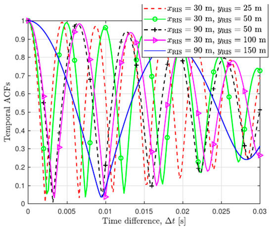
Figure 2.
Temporal ACFs of proposed channel model with varied RIS deployments.
Figure 3 shows the temporal autocorrelation functions of the RIS-assisted base station to unmanned ground vehicle channel model under different Rician factors. It is evident that as the Rician factor decreases from 30 to 0.03, the temporal correlation weakens as increases from 0 to 0.08 s. Overall, for curves corresponding to different Rician factors, the temporal correlation gradually decays as the time difference increases, reflecting the non-stationary characteristics of the channel in the time domain. These results are consistent with the simulation findings in [40], thereby verifying the accuracy of the temporal ACFs derived from the proposed channel model. Specifically, in scenarios with higher factors, RIS-FAS configuration can significantly mitigate the ACF decay rate and increase its temporal stability, while in scenarios with lower factors, the performance gain of FAS-RIS diminishes as the factor decreases. Compared with single-RIS configurations in [40], the FAS-RIS scheme demonstrates higher temporal stability and slower decay. Therefore, in order to improve communication quality, a higher value should be adopted in the FAS-RIS communication system to achieve high temporal correlation. This outcome validates the accuracy of the derived temporal autocorrelation functions (ACFs) and confirms the reliability of the simulation results for the proposed channel model.
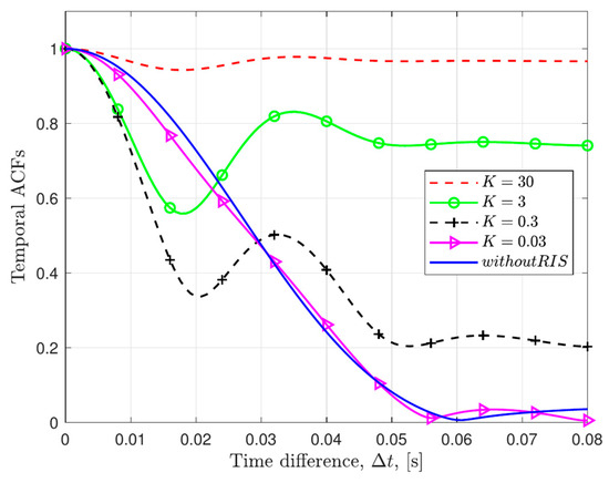
Figure 3.
The temporal ACFs of the proposed channel model with respect to the Rician factor K.
Figure 4 demonstrates the temporal autocorrelation features of the proposed channel model under various motion times and spatial positions of the RIS array. The simulation outcomes reveal that the temporal autocorrelation traits among transmission paths display disparate trends contingent upon the values assigned to the motion time parameter. This clearly shows that the proposed model has non-stationary attributes in the time domain. Moreover, as the motion time progresses, the reduction within the time correlation curve of the developed channel model becomes notably more pronounced, further validating its non-stationary temporal behavior.
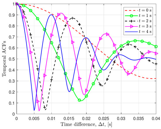
Figure 4.
Temporal ACFs of proposed channel model at varying time instants.
Figure 5 depicts the variations in the temporal autocorrelation function (ACF) of the proposed channel model, under diverse motion directions and velocities of the unmanned ground vehicle. The speed of the unmanned ground vehicle (UGV) is set around ~6 m/s (15.3~21.6 km/h) to reflect typical urban mobility characteristics, which enables the effective testing of the Doppler effect. It can be observed that for curves corresponding to different mobility parameters, the ACF values exhibit a sharp decline with small before gradually stabilizing as increases. These results match the simulation data in [40], further confirming the accuracy of the temporal ACFs derived from the proposed channel model.
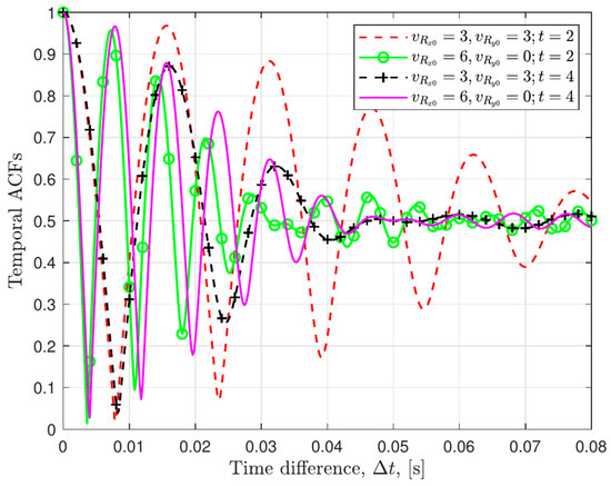
Figure 5.
The temporal ACFs of the proposed channel model related to the motion velocities of the UGV.
Figure 6 depicts the temporal autocorrelation function (ACF) of the proposed channel model under different distance parameters . The simulation results demonstrate that varying the distance parameters leads to distinct spatial autocorrelation characteristics among different transmission paths. This highlights the non-stationary nature of the proposed model in the time domain, as evidenced by the diverse temporal trends. The attenuation rates of the curves are different, and the smaller the , the faster the attenuation. When the distance parameter exceeds 150 m, the system enters the far-field communication region, and at this time, the attenuation rate of the ACF slows down significantly. In addition, by comparing the simulation curves under different distance configurations, it can be found that as the distance parameter increases from 30 m to 300 m, the temporal correlation of the channel gradually increases.
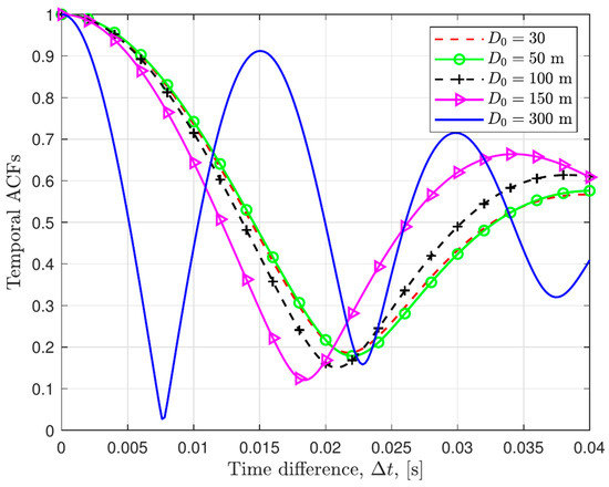
Figure 6.
Temporal ACFs of proposed channel model under different distance parameters .
Figure 7 depicts the accuracy of the proposed channel model under different RIS dimensions and time instants. As the RIS dimension increases, the simulation results indicate that the modeling error (in dB) generally shows an upward trend.
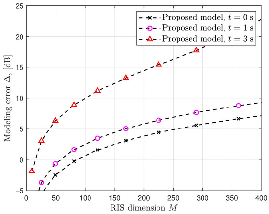
Figure 7.
Modeling accuracy of proposed channel model.
Specifically, the error growth rate varies at different time points. The curve corresponding to seconds shows a sharper increase in the modeling error compared to the other two curves. This demonstrates that the proposed model exhibits different performance characteristics in terms of modeling accuracy at different time instants, and the RIS dimension has a significant impact on the modeling error. This provides important references for further optimizing the model and understanding its performance in various scenarios.
This study develops a comprehensive near-field channel modeling framework by incorporating the signal propagation dynamics of RISs while simultaneously capturing the interdependent non-stationary behaviors across three critical domains: spatial, temporal, and spectral.
Within the spatial domain, the framework accounts for electromagnetic field variations in the near-field region. For the temporal domain, it models time-evolving channel characteristics. Regarding the spectral domain, it characterizes frequency-dependent propagation effects. Furthermore, the proposed methodology establishes analytical relationships between these multidimensional channel properties and key system performance metrics through rigorous mathematical mapping.
6. Conclusions
This paper addressed a novel three-dimensional channel model for air–ground communication, which combines RISs with fluid antenna systems. In this model, the base station (BS) transmits information signals to the unmanned ground vehicle equipped with an FAS, assisted by the reconfigurable intelligent surface. By adjusting the configuration of channel parameters, various types of FAS-RIS communication scenarios can be described.
Simulations indicate that the autocorrelation function (ACF) of the channel is affected by multiple factors. Specifically, it is found that both the increase in motion time and the decrease in the Rician factor lead to a gradual weakening of the temporal correlation of the channel. Moreover, the motion speed and direction of the UGV also impact the channel’s temporal correlation. These simulation outcomes offer significant technical references for the subsequent research and development of RIS-FAS communication systems, facilitating more informed design decisions and a further exploration of related technologies.
Despite the progress made in this study, the integration of reconfigurable intelligent surfaces and fluid antenna systems in air–ground communications still faces several unresolved challenges that require further research. First, in terms of real-time optimization, mobile scenarios demand low-latency algorithms to adapt RIS phase shifts and FAS port configurations under rapidly changing channel conditions. Second, regarding hardware limitations, we need to improve RIS phase shifter resolution, reduce FAS switching delays, and optimize the energy efficiency trade-offs to make these systems practical for real-world deployment. Furthermore, integrating RIS-FAS architectures with emerging 6G standards will require coordinated efforts across different protocol layers to ensure seamless interoperability. Addressing these challenges will enable RIS-FAS to realize their full potential in future wireless networks.
Author Contributions
Writing—original draft, Y.J.; Writing—review & editing, Y.J.; Visualization, Y.J.; Supervision, X.C. All authors have read and agreed to the published version of the manuscript.
Funding
This research received no external funding.
Data Availability Statement
The original contributions presented in this study are included in the article. Further inquiries can be directed to the corresponding author.
Conflicts of Interest
The authors declare no conflict of interest.
References
- Jiang, H.; Mukherjee, M.; Zhou, J.; Lloret, J. Channel modeling and characteristics analysis for 6G wireless communications. IEEE Netw. 2021, 35, 296–303. [Google Scholar] [CrossRef]
- Jiang, H.; Shi, W.; Chen, X.; Zhu, Q.; Chen, Z. High-efficient near-field channel characteristics analysis for large-scale MIMO communication systems. IEEE Internet Things J. 2025, 12, 7446–7458. [Google Scholar] [CrossRef]
- Mao, K.; Zhu, Q.; Wang, C.-X.; Ye, X.; Gomez-Ponce, J.; Cai, X.; Miao, Y.; Cui, Z.; Wu, Q.; Fan, W. A survey on channel sounding technologies and measurements for UAV-assisted communications. IEEE Trans. Instrum. Meas. 2024, 73, 8004624. [Google Scholar] [CrossRef]
- Ruan, C.; Zhang, Z.; Jiang, H.; Dang, J.; Wu, L.; Zhang, H. Wideband near-field channel covariance estimation for XL-MIMO systems in the face of beam split. IEEE Trans. Veh. Technol. 2024, 74, 2912–2926. [Google Scholar] [CrossRef]
- Ruan, C.; Zhang, Z.; Jiang, H.; Zhang, H.; Dang, J.; Wu, L. Simplified learned approximate message passing network for beamspace channel estimation in mmWave massive MIMO systems. IEEE Trans. Wirel. Commun. 2024, 23, 5142–5156. [Google Scholar] [CrossRef]
- Wang, J.; Xiao, J.; Zou, Y.; Xie, W.; Liu, Y. Wideband Beamforming for RIS Assisted Near-Field Communications. IEEE Trans. Wirel. Commun. 2024, 23, 16836–16851. [Google Scholar] [CrossRef]
- Mao, K.; Zhu, Q.; Qiu, Y.; Liu, X.; Song, M.; Fan, W.; Kokkeler, A.B.J.; Miao, Y. A UAV-aided real-time channel sounder for highly dynamic nonstationary A2G scenarios. IEEE Trans. Instrum. Meas. 2023, 72, 6504515. [Google Scholar] [CrossRef]
- Lian, Z.; Wang, Y.; Su, Y.; Ji, P.; Ling, L.; Zhang, Z.; Jin, B.; Luo, H. A novel beam channel model and capacity analysis for UAV-enabled millimeter-wave communication systems. IEEE Trans. Wirel. Commun. 2024, 23, 3617–3632. [Google Scholar] [CrossRef]
- Chen, Z.; Guo, Y.; Zhang, P.; Jiang, H.; Xiao, Y.; Huang, L. Physical layer security improvement for hybrid RIS-assisted MIMO communications. IEEE Commun. Lett. 2024, 28, 2493–2497. [Google Scholar] [CrossRef]
- Wu, Q.; Zhang, R. Intelligent reflecting surface enhanced wireless network via joint active and passive beamforming. IEEE Trans. Wirel. Commun. 2019, 18, 5394–5409. [Google Scholar] [CrossRef]
- Xiong, B.; Zhang, Z.; Jiang, H. Reconfigurable intelligent surface for mmWave mobile communications: What if LoS path exists? IEEE Wirel. Commun. Lett. 2023, 12, 247–251. [Google Scholar] [CrossRef]
- Jiang, H.; Xiong, B.; Zhang, H.; Basar, E. Physics-based 3D end-to-end modeling for double-RISs assisted non-stationary UAV-toground communication channels. IEEE Trans. Commun. 2023, 71, 4247–4261. [Google Scholar] [CrossRef]
- Jiang, H.; He, R.; Ruan, C.; Zhou, J.; Chang, D. Three-dimensional geometry-based stochastic channel modeling for intelligent reflecting surface-assisted UAV MIMO communications. IEEE Wirel. Commun. Lett. 2021, 10, 2727–2731. [Google Scholar] [CrossRef]
- Jiang, H.; Shi, W.; Zhang, Z.; Panet, C.; Wu, Q.; Shu, F.; Liu, R.; Chen, Z.; Wang, J. Large-scale RIS enabled air-ground channels: Near-field modeling and analysis. IEEE Trans. Wirel. Commun. 2024, 24, 1074–1088. [Google Scholar] [CrossRef]
- Lian, Z.; Zhang, W.; Wang, Y.; Su, Y.; Zhang, B.; Jin, B.; Wang, B. Physics-based channel modeling for IRS-assisted mmWave Communication systems. IEEE Trans. Commun. 2024, 72, 2687–2700. [Google Scholar] [CrossRef]
- Chen, Z.; Huang, L.; So, H.C.; Jiang, H.; Zhang, X.Y.; Wang, J. Deep reinforcement learning over RIS-assisted integrated sensing and communication: Challenges and opportunities. IEEE Veh. Technol. Mag. 2024; early access. [Google Scholar] [CrossRef]
- Wu, Q.; Zhang, R. Weighted sum power maximization for intelligent reflecting surface aided SWIPT. IEEE Wirel. Commun. Lett. 2019, 9, 586–590. [Google Scholar] [CrossRef]
- Zhu, J.; Huang, Y.; Wang, J.; Navaie, K.; Ding, Z. Power efficient IRS-assisted NOMA. IEEE Trans. Commun. 2021, 69, 900–913. [Google Scholar] [CrossRef]
- Yang, Y.; Gong, Y.; Wu, Y. Intelligent-reflecting-surface-aided mobile edge computing with binary offloading: Energy minimization for IoT devices. IEEE Internet Things J. 2022, 9, 12973–12983. [Google Scholar] [CrossRef]
- Wang, J.; Zhu, Q.; Lin, Z.; Chen, J.; Ding, G.; Wu, Q.; Gu, G.; Gao, Q. Sparse bayesian learning-based hierarchical construction for 3D radio environment maps incorporating channel shadowing. IEEE Trans. Wirel. Commun. 2024, 23, 14560–14574. [Google Scholar] [CrossRef]
- Ma, Z.; Zhang, R.; Ai, B.; Lian, Z.; Zeng, L.; Niyato, D.; Peng, Y. Deep reinforcement learning for energy efficiency maximization in RSMA-IRS-assisted ISAC system. IEEE Trans. Veh. Technol. 2025; early access. [Google Scholar] [CrossRef]
- Zeng, L.; Liao, X.; Xie, W.; Ma, Z.; Xiong, B.; Jiang, H. UAV-to-ground channel modeling: (Quasi-)Closed-form channel statistics and manual parameter estimation. China Commun. 2024, 10, 100–115. [Google Scholar]
- Zeng, L.; Liao, X.; Ma, Z.; Liu, W.; Jiang, H.; Chen, Z. Toward more adaptive UAV-to-UAV GBSMs: Introducing the extended vMF distribution. IEEE Wirel. Commun. Lett. 2025, 14, 260–264. [Google Scholar] [CrossRef]
- Zhu, L.; Wong, K.-K. Historical review of fluid antennas and movable antennas. arXiv 2024, arXiv:2401.02362v2. [Google Scholar] [CrossRef]
- Yang, N.; Jiang, H.; Guo, D.; Liu, Y.; Ding, G.; Chen, Z.; Yang, Z. Proof of reputation: A blockchain-based countermeasure to defend against massive SSDF in cognitive radio networks. IEEE Commun. Lett. 2024, 28, 2693–2697. [Google Scholar] [CrossRef]
- Wong, K.-K.; Shojaeifard, A.; Tong, K.-F.; Zhang, Y. Fluid antenna systems. IEEE Trans. Wirel. Commun. 2021, 20, 1950–1962. [Google Scholar] [CrossRef]
- Wong, K.-K.; Tong, K.; Zhang, Y.; Zhongbin, Z. Fluid antenna system for 6G: When Bruce Lee inspires wireless communications. Electron. Lett. 2020, 56, 1288–1290. [Google Scholar] [CrossRef]
- Wong, K.-K.; Tong, K.-F.; Chen, Y.; Zhang, Y. Fast fluid antenna multiple access enabling massive connectivity. IEEE Commun. Lett. 2023, 27, 711–715. [Google Scholar] [CrossRef]
- Hua, B.; Han, L.; Zhu, Q.; Wang, C.-X.; Mao, K.; Bao, J.; Chang, H.; Tang, Z. Ultra-wideband nonstationary channel modeling for UAV-to-ground communications. IEEE Trans. Wirel. Commun. 2025, 24, 4190–4204. [Google Scholar] [CrossRef]
- New, W.-K.; Wong, K.-K.; Xu, H.; Tong, K.-F.; Chae, C.-B. Fluid antenna system: New insights on outage probability and diversity gain. IEEE Trans. Wirel. Commun. 2024, 23, 128–140. [Google Scholar] [CrossRef]
- Wong, K.-K.; Tong, K.-F.; Chen, Y.; Zhang, Y. Closed-form expressions for spatial correlation parameters for performance analysis of fluid antenna systems. IET Elect. Lett. 2022, 58, 454–457. [Google Scholar] [CrossRef]
- Khammassi, M.; Kammoun, A.; Alouini, M.-S. A new analytical approximation of the fluid antenna system channel. IEEE Trans. Wirel. Commun. 2023, 22, 8843–8858. [Google Scholar] [CrossRef]
- Yao, J.; Lai, X.; Zhi, K.; Wu, T.; Jin, M.; Pan, C.; Elkashlan, M.; Yuen, C.; Wong, K.K. A Framework of FAS-RIS Systems: Performance Analysis and Throughput Optimization. arXiv 2024, arXiv:2407.08141. [Google Scholar] [CrossRef]
- Yao, J.; Zheng, J.; Wu, T.; Jin, M.; Yuen, C.; Wong, K.-K. FAS-RIS Communication: Model, Analysis, and Optimization. IEEE Trans. Veh. Technol. 2025, 74, 9938–9943. [Google Scholar] [CrossRef]
- Lai, X.; Yao, J.; Zhi, K.; Wu, T.; Morales-Jimenez, D.; Wong, K.-K. FAS-RIS: A Block-Correlation Model Analysis. IEEE Trans. Veh. Technol. 2025, 74, 3412–3417. [Google Scholar] [CrossRef]
- Zheng, J.; Lai, X.; Yao, J.; Tang, J.; Pan, Y.; Wu, T.; Yuen, C. Paving the Way to 6G: Outage Probability Analysis for FAS-ARIS Systems. arXiv 2024, arXiv:2411.01398. [Google Scholar]
- Najafi, M.; Jamali, V.; Schober, R.; Poor, H.V. Physics-based modeling and scalable optimization of large intelligent reflecting surfaces. IEEE Trans. Commun. 2021, 69, 2673–2691. [Google Scholar] [CrossRef]
- Lai, X.; Wu, T.; Yao, J.; Pan, C.; Elkashlan, M.; Wong, K.-K. On performance of fluid antenna system using maximum ratio combining. IEEE Commun. Lett. 2024, 28, 402–406. [Google Scholar] [CrossRef]
- Tang, B.; Xu, H.; Wong, K.-K.; Tong, K.-F.; Zhang, Y.; Chae, C.-B. Fluid antenna enabling secret communications. IEEE Commun. Lett. 2023, 27, 1491–1495. [Google Scholar] [CrossRef]
- Jiang, H.; Xiong, B.; Zhang, H.; Basar, E. Hybrid far- and near-field modeling for reconfigurable intelligent surface assisted V2V channels: A sub-array partition based approach. IEEE Trans. Wirel. Commun. 2023, 22, 8290–8303. [Google Scholar] [CrossRef]
Disclaimer/Publisher’s Note: The statements, opinions and data contained in all publications are solely those of the individual author(s) and contributor(s) and not of MDPI and/or the editor(s). MDPI and/or the editor(s) disclaim responsibility for any injury to people or property resulting from any ideas, methods, instructions or products referred to in the content. |
© 2025 by the authors. Licensee MDPI, Basel, Switzerland. This article is an open access article distributed under the terms and conditions of the Creative Commons Attribution (CC BY) license (https://creativecommons.org/licenses/by/4.0/).