1. Introduction
Data compression is an indispensable technology in computation and communication systems, playing a pivotal role in reducing storage requirements, enhancing transmission efficiency, and optimizing energy consumption [
1,
2,
3]. Among compression techniques, lossless methods enable compact data representation without information loss, preserving data integrity—a critical requirement in fields such as medical imaging, scientific datasets, and financial records [
4,
5]. In consumer electronics, where rapid processing, limited storage, and efficient transmission are paramount, the development of high-performance lossless compression algorithms remains a significant research focus.
A major class of lossless compression techniques is dictionary-based compression, originally introduced by Lempel and Ziv. These algorithms, including LZ77 [
6], LZ4 [
7], LZW [
8], LZRW [
9], LZSS [
10], and Snappy [
11], achieve compression by replacing repeated sequences of data with references to a dynamically constructed dictionary. Due to their ability to efficiently handle repetitive patterns, they are widely used in text compression, log file storage, and network protocols. However, software implementations of these algorithms often struggle to meet the throughput requirements of high-speed data processing systems.
To overcome these limitations, field programmable gate arrays (FPGAs) have emerged as a powerful acceleration platform, offering parallel processing capabilities, low-latency execution, and energy efficiency. The programmable logic units within FPGAs consist of Look-Up Tables (LUTs), Flip-Flops, and other basic logic elements, capable of performing complex logic operations and data processing [
12]. FPGA-based compression architectures are particularly well-suited for computationally intensive tasks, enabling real-time data processing in applications such as high-frequency trading, network packet compression, and embedded storage systems [
13].
Early research in FPGA-accelerated compression primarily focused on entropy coding techniques, such as Huffman coding and arithmetic coding, which exploit statistical redundancies in data. In 1994, Howard and Vitter [
14] proposed a dynamic Huffman coding architecture that leverages parallel frequency counting and tree generation to minimize encoding latency. Further optimizations were later introduced by Garikipati et al. [
3], who combined Huffman coding with run-length encoding (RLE) to improve compression efficiency while reducing power consumption. Recently, Guguloth et al. [
15] introduced a modern hardware architecture based on the Canonical Huffman encoding and decoding computation method, integrated with frequency counting, sorting, state machine optimization, and barrel shifter techniques, which minimizes memory storage requirements and utilizes fewer hardware resources.
With the increasing adoption of dictionary-based algorithms, researchers have explored FPGA optimizations for LZ-family compression. Bartik et al. [
16] analyzed the LZ4 algorithm’s suitability for hardware implementation, highlighting its trade-offs between throughput and resource utilization. Choi et al. [
17] developed a reconfigurable LZ77 architecture that supports two operational modes—throughput-first (TF) and compression ratio-first (CF)—by dynamically adjusting the degree of parallelism during string matching. Gao et al. [
18] propose MetaZip, improving the compression throughput within the constraints of FPGA resources by adopting an adaptive parallel-width pipeline.
Zstd combines LZ77 compression and entropy encoding, suitable for the compression of big data sets, such as HFT data. However, Zstd involves many complex high-sequential operations, which consume a significant amount of CPU resources during actual deployment [
19]. Refs. [
20,
21] introduced architectures of hardware compression kernel for Zstd that allows the algorithm to be used for real-time compression of big data streams. Ref. [
22] proposed a pipelined dynamic table FSE accelerator on FPGA to mitigate the compression performance loss.
Snappy compression algorithm, known for its fast compression and decompression speeds, has widespread applications in large-scale data processing and communication systems, including search engines [
23], log analysis [
24], and image and video processing [
25]. Since the Snappy compression algorithm is a lightweight and fast compression algorithm designed primarily for software, deploying Snappy on FPGA platforms still encounters limitations and challenges:
Snappy relies on a hash table for its dictionary, storing fixed-length strings starting at each byte, along with an input buffer for backward referencing. This setup leads to considerable redundancy between the dictionary and input buffer, wasting storage space.
The algorithm performs hash computations only for non-matching characters; hence, partial matches do not contribute to the hash values stored in the dictionary [
26].
Snappy inherently supports encoding of match lengths up to 64 bytes, necessitating the segmentation of longer matching sequences into multiple smaller ones, resulting in suboptimal coding efficiency.
To address these issues, this paper proposes an optimized FPGA-based Snappy compression architecture with the following solutions:
Replacement of raw data entries in the dictionary with fingerprints, thereby eliminating redundant storage.
Inclusion of both matching and non-matching data in the hash dictionary, aiming to elevate the compression ratio.
An enhancement to the Snappy encoding format that fully utilizes the trailing two bits of its token structure, enabling support for long matches up to 1024 bytes, thereby boosting the compression ratio and addressing the limitation on match length.
This paper is organized as follows:
Section 2 provides a review of the Snappy algorithm, including its encoding format and operational steps, along with an overview of previous hardware implementations.
Section 3 introduces our enhanced Snappy encoding format, as well as the design of hash functions and fingerprints. In
Section 4, we propose a hardware architecture tailored for our enhanced Snappy algorithm. Experimental results of our FPGA implementation and comparisons with other FPGA hardware designs are presented in
Section 5. Finally,
Section 7 summarizes the findings and conclusions of this paper.
3. Proposed Method
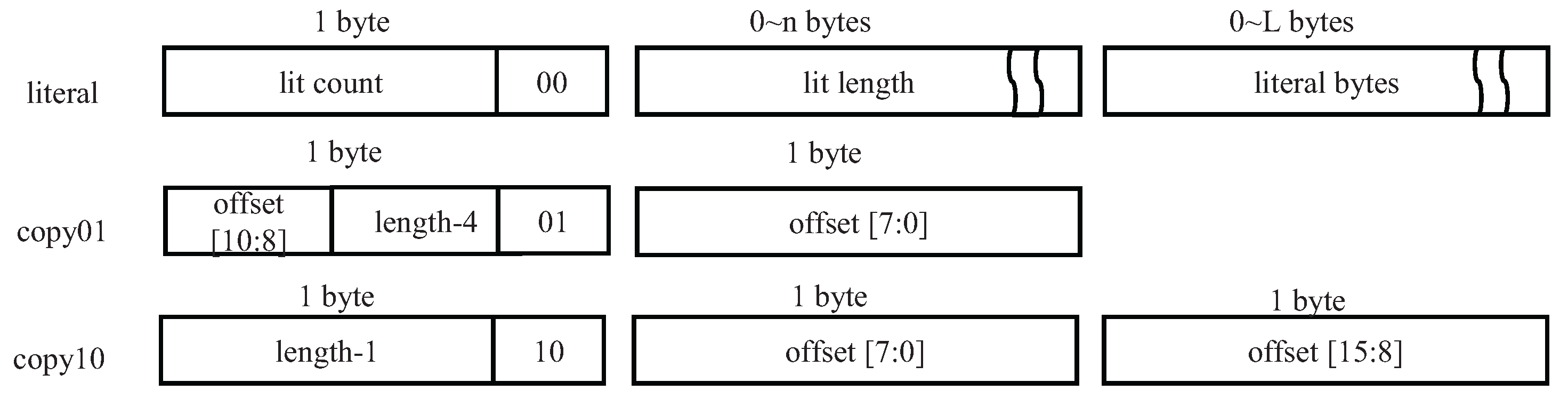
3.1. Enhanced Snappy Coding Format
Snappy’s original format utilizes three token types (0b00, 0b01, 0b10). However, Google’s extension [
11] introduces a fourth type (0b11 in the least significant two bits) specifically for copy operations with match lengths less than or equal to 64 bytes and offsets falling within the range of
to
, inclusive. As shown in
Table 1, this extension accommodates longer distance back-references without necessitating larger tokens or more complex encoding methods.
In FPGA compression, the constrained on-chip memory limits the hash table and input buffer sizes, imposing an that reduces encounters with long back-references. Despite this constraint, there remains a relatively high probability of encountering long match lengths during compression. According to Snappy’s design, when the length of a matched string exceeds 64 bytes, it must be encoded into multiple consecutive copy type segments, potentially leading to decreased encoding efficiency.
We conducted experiments using the Silesia dataset across both software-based Google Snappy [
11] and Xilinx Snappy FPGA implementation [
30]. With a hash table configuration of 4096 entries and six hash slots,
Figure 2 reveals that longer matches are more frequently detected in the hardware realization compared to long offsets. Here, “long-match” indicates match lengths exceeding 64 bytes, while “long-offset” signifies back-reference offsets exceeding
.
The observed disparity arises from differences in hashing strategies: Google Snappy’s software version primarily utilizes its hash table for indexing, whereas Xilinx’s hardware implementation includes storage for both indices and partial string data. Furthermore, Xilinx’s Snappy design incorporates a Best Match Filter module, which optimizes match length identification, enhancing the hardware solution’s capacity to detect and leverage longer matches.
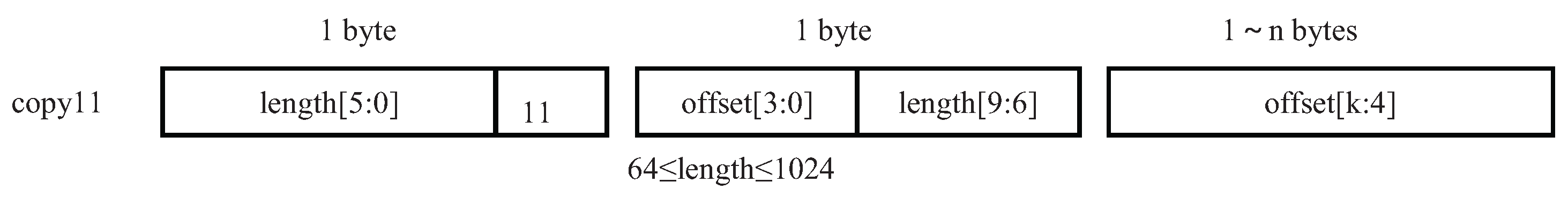
In this work, we propose an enhanced encoding strategy for the 0b11 token type, specifically tailored to improve compression performance in hardware-accelerated Snappy implementations. Unlike Google’s extension, which focuses on supporting larger offsets, our design prioritizes longer match lengths by redefining the 0b11 token to represent copy operations with lengths up to 1024 bytes, as illustrated in
Figure 3 and
Table 1. This enhancement is particularly beneficial for hardware-based compression, where longer matches significantly improve the compression ratio and reduce the number of tokens generated.
We set 1024 bytes as the maximum match length based on experimental studies showing that longer matches are extremely rare in real-world datasets—our analysis of the Silesia corpus revealed that 99.998% of matches fall within this limit. For the remaining 0.002% of cases where matches exceed 1024 bytes, the algorithm automatically splits them into multiple segments (each no more than 1024 bytes) and encodes them as separate tokens, ensuring complete coverage while maintaining format compatibility.
For offset encoding in this enhanced token, we introduce a variable-length encoding scheme that starts with 4 bits from the second token byte, followed by additional bytes as needed. In this scheme, the most significant bit (MSB) of each byte acts as a continuation flag: a value of 1 indicates that more bytes follow, while 0 marks the end of the offset encoding.
This design offers several advantages: In a 16 KB input buffer, where the maximum offset is 14 bits, our encoding requires only 3 bytes for the offset (4-bit base + 2 continuation bytes), resulting in a total of 4 bytes per Token 11. In contrast, Google’s Token 11 uses a fixed 4-byte offset field, resulting in a total of 5 bytes per token—one byte more than our design. For larger buffers, the variable-length encoding allows the offset to grow as needed, while maintaining backward compatibility and avoiding unnecessary overhead for smaller offsets. Empirical analysis shows that longer offsets occur with significantly lower probability in real-world data. Therefore, variable-length encoding is particularly suitable—shorter offsets are encoded compactly, and longer ones are only represented when necessary, minimizing bit consumption.
These optimizations improve algorithmic efficiency, particularly for long matches, enabling better utilization of Snappy’s compression capabilities and increasing overall compression performance.
3.2. Hash Table
The Snappy compression algorithm relies on a hash table acting as a dictionary, storing reference data from a sliding window in on-chip RAM within an FPGA. This hash table employs a fixed number of slots to accommodate entries, with the sliding window data and corresponding file indices inserted into this dictionary. In cases of hash collisions, where multiple entries map to the same slot, the earliest-entered slot is replaced with the most recent data due to the limited capacity.
We adopt the hash algorithm proposed by [
33], expressed as follows:
where
W is the 32-bit
data in a sliding window.
This hashing function masks the result by 12 bits, effectively mapping a 32-bit value to a 12-bit one using only bitwise operations [
33]. Consequently, the hardware resources required for calculating Equation (
1) are minimal, and the process itself takes only two clock cycles.
3.3. Fingerprint Design
In the typical Snappy configuration [
30,
40], the minimum match length
is standardized to 4 bytes. Within this setup, each slot in the hash table contains the following:
where
occupies 3 bytes and the sliding window data
to
requires 6 bytes. This results in a total storage requirement of 9 bytes per slot to identify a potential match.
To optimize storage usage and minimize clock cycles, our study adopts a strategy that retains only fingerprints for the bytes, while preserving the original values for any exceeding bytes in the sliding window. This approach aims to leverage the efficiency of fingerprint matching in identifying potential matches between the sliding window and entries in the hash table.
Although there exists a possibility of misjudgments during fingerprint comparison, such occurrences are mitigated through a multi-step process. Initially, the hash table matching is performed based on fingerprints, followed by a backward match module. This module compares the sliding window data against the original data buffered in the input buffer, thereby ensuring the accuracy and integrity of the final compression encoding.
In our approach, with a 6−byte sliding window (
,
,
,
,
,
) and a 4−byte
, each entry in the hash table slot comprises 3−byte indices and 3−byte data values:
resulting in a compact 6−byte storage format. This represents a significant improvement over conventional Snappy designs [
30,
40], which store complete sliding window data in each slot. Specifically, our approach reduces storage requirements by one-third compared to these traditional implementations when using a 6−byte sliding-window configuration.
We employ a hash function to compute the fingerprint of the minimal match data
W, composed of four bytes:
. The fingerprint of
W can be expressed as follows:
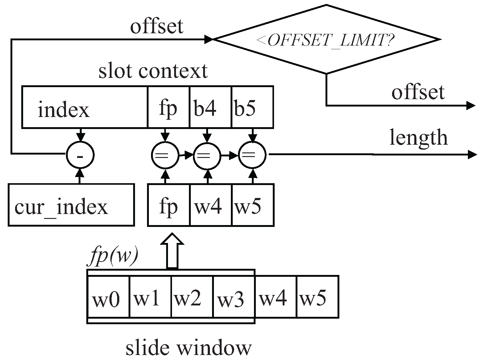
Figure 4 illustrates the computational workflow for hash table matching within a single slot. Initially, the fingerprint of the sliding window is computed using Equation (4) and compared against the fingerprint stored in each slot. A match indicates a potential
−byte (4−byte in
Figure 4) length match. Subsequently, the remaining bytes of the sliding window are compared with those stored in the slot to determine the overall match length.
Finally, the offset is calculated by finding the difference between the index stored in the hash table and the current index of the first character in the sliding window. If this difference is less than a predefined threshold , the match is considered valid.
4. Hardware Implementation
4.1. FPGA Architecture of Snappy Compression Algorithm
In contrast to its software-based counterpart, hardware-accelerated implementations of the Snappy algorithm offer significant enhancements in efficiency and speed within constrained resource environments. This acceleration is achieved through the optimization of key operations such as hash computations, dictionary lookups, and backward matching, which are traditionally performed sequentially in software implementations [
40]. However, by leveraging the inherent parallelism of FPGA architectures, hardware implementations enable pipelined execution of these operations, thereby unlocking the potential for substantial performance gains.
The hardware architecture proposed in this study, as illustrated in
Figure 5, comprises five essential components: the input controller, the input buffer, the pre-match module, the backward match module, and the Snappy encoder. These components work seamlessly together to efficiently process incoming data streams and generate compressed output in the Snappy format.
The input controller serves as the interface between the FPGA and the external memory, facilitating the retrieval of 8-bit data streams for processing. Upon fetching, the data is stored in the input buffer, where it undergoes subsequent processing stages.
The pre-match module computes hash values and fingerprints to identify potential matches in a hash table, concurrently updating the input buffer. Matches exceeding the minimum threshold length trigger the intervention of the backward match module, which further analyzes the data to determine precise match lengths by referencing the circular input buffer.
Following the identification of matches, the data is directed to separate literal and copy streams, which are then fed into the Snappy encoder. Here, the data is encoded according to the Snappy compression format, as depicted in
Figure 1 and
Figure 3.
The pre-match module includes a word shift register, a hash engine, an FP (fingerprint) engine, a hash table, a slot match, an index counter, and a best match filter.
Together, these components facilitate the transformation of input bytes into a sliding window, the computation of hash values and fingerprints, the comparison of hash table entries with sliding window content, the determination of match lengths and offsets, and the validation of match accuracy.
Inspired by the Xilinx’s Snappy compressor [
30], our design incorporates a best match filter within the pre-match module. This filter optimizes match selection by comparing match lengths initiated by the current byte with those starting from subsequent sliding window-size bytes. If a longer match is detected, its match length is adjusted to zero, ensuring that only the longest matches are considered for compression, thus enhancing overall compression efficiency.
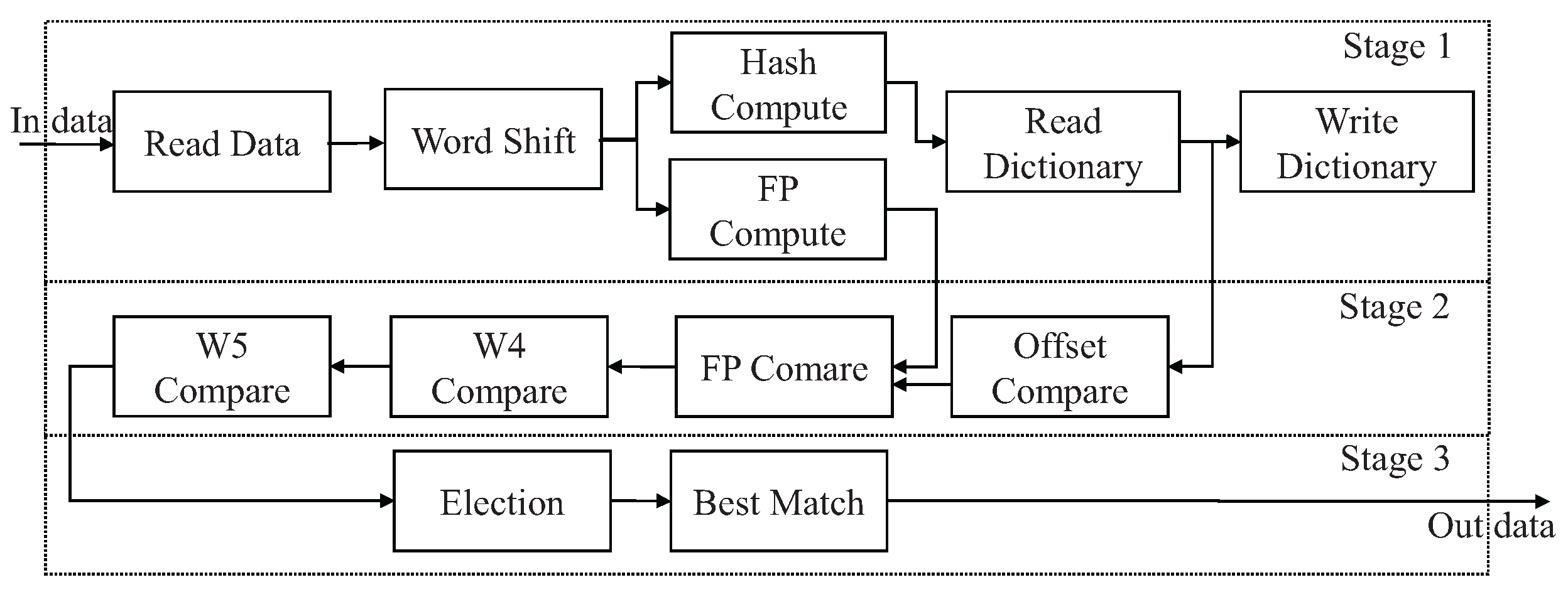
4.2. Pipelined Architecture and Parallelization in Pre-Match Module
In the pre-match module, the Snappy algorithm is optimized for FPGA implementation through its repetitive and unidirectional treatment of individual bytes. This characteristic facilitates a pipelined approach, enhancing efficiency. Illustrated in
Figure 6, the pre-match module features a 10-stage pipelined architecture, organized into three distinct stages.
The initial stage encompasses tasks such as data reading, word shifting, hash and fingerprint computations, dictionary reading, and dictionary writing. The dictionary writing task updates the hash table, which makes the dictionary reading task access the updated data next time. Following this, the second stage executes the parallelized slot match unit, where sliding window data undergoes comparison against entries in a hash table. Finally, the third stage selects the historical position with the maximum match length from the results obtained in the preceding parallel comparisons.
Within the second stage, the time required for matching a single slot, , involves one offset comparison, one fingerprint comparison, and two data comparisons, each completed within a single clock cycle. Thus, . Initially, the cumulative match time for six slots in stage 2 totals .
Leveraging the independence of slot data matches, parallelization becomes feasible. Through employing six matching resources in parallel, the aggregate match time is reduced to .
Within the pre-match module, each component operates within a single clock cycle, allowing the algorithm to process one byte of data per average clock cycle once initiated. This streamlined approach ensures efficient data processing and contributes to the overall performance of the system.
While pipeline architectures are commonly employed in FPGA-based designs [
30,
40], our implementation uniquely incorporates three key innovations within the pipeline stages: (1) fingerprint-based dictionary matching, (2) extended token11 encoding/decoding, and (3) inclusive hash dictionary management.
5. Result and Comparison
5.1. Experimental Setup
The proposed Snappy compression architecture has been implemented and rigorously evaluated on an AMD Alveo U200 acceleration card. The design features a configurable input buffer size of 16KB and an optimized hash table structure comprising 4096 entries with six slots per entry. The resource utilization of a single compression implementation is listed in
Table 2, along with the proportion of each resource within the total chip resources.
To ensure comprehensive evaluation, we verified bit-level accuracy against the canonical Snappy implementation using the Silesia corpus, Canterbury corpus, and Calgary corpus. We evaluated both single-kernel and multi-kernel configurations.
5.2. Experimental Results
Compression ratio. The Silesia corpus is a carefully curated benchmark dataset designed for evaluating compression algorithms [
41], comprising files with diverse characteristics. In
Figure 7a, the Silesia benchmark revealed that our implementation achieves superior compression ratios ranging up to 6.2 (original/compressed), averaging at 2.27, representing a 6.1% improvement over Xilinx’s Vitis solution [
30].
We further evaluated our implementation on the Canterbury and Calgary corpora. As shown in
Figure 7b, our method achieves competitive average compression ratios across these datasets, with error bars indicating standard deviation. While the results demonstrate robust performance in multi-corpus scenarios, our implementation exhibits slightly higher variance compared to Xilinx’s design [
30].
Clock Frequency. Each compression kernel achieves a post-place-and-route verified maximum frequency of 320 MHz (3.125 ns period). For direct comparison with the Xilinx reference design [
30], we implemented a single-kernel configuration operating at 300 MHz, achieving 279 MB/s throughput. Scaling up to an array of eight hardware kernels, each operating at the same 300 MHz frequency, enhances the system’s throughput capability to 1.6 GB/s.
As shown in
Table 3, while our implementation achieves comparable throughput (279 MB/s vs. 280 MB/s) in single-kernel operation at 300 MHz, the scaled eight-kernel configuration shows marginally lower aggregate throughput compared to Xilinx’s state-of-the-art design [
30]. This difference stems from fundamental architectural trade-offs in our optimization approach.
Power consumption. Power characterization was performed using Vivado 2022.1’s post-route power analysis with SAIF activity files from the Silesia corpus benchmark simulation. The measurements show our single-kernel implementation consumes 16.2 W (on-chip power) when operating at 300 MHz, including all compression core logic and associated on-chip memory subsystems.
5.3. Key Performance-Influencing METRICS
The proposed optimizations, including the enhanced encoding format and inclusive hash dictionary, aim to improve the compression ratio. Additionally, the slot number and hash table size significantly impact implementation performance. To systematically evaluate these key factors, we analyze five distinct configurations (
Table 4) across three benchmark corpora.
Figure 8 presents the corresponding compression ratios, demonstrating the effectiveness of each optimization.
Enhanced encoding format. The comparison between the baseline and Configuration 2 reveals the contribution of the enhanced encoding format to the improvement in compression ratio. The absence of enhanced encoding results in an average compression ratio degradation of 4.13%.
Inclusive hash dictionary. An experimental comparison between the baseline and Configuration 3 demonstrates that inclusively storing both matching and non-matching data can improve the compression ratio by 47.24%. This improvement is attributed to the limited dictionary size in hardware compared to software; storing only non-matching data reduces the likelihood of finding potential matches within the dictionary.
Slot number. The slot number represents the parallelism level of the hash table. Comparisons between the baseline and Configurations 4 and 5 reveal that the slot number affects the compression ratio: in general, a higher number of slots leads to a higher compression ratio. Specifically, using four slots results in a 1.76% decrease compared to six slots, while using eight slots only brings a 0.88% increase. This is because as more slots are configured, the hash table grows larger; however, once the table is sufficiently large to accommodate all input data, further increases yield-diminishing returns.
Hash table size. To investigate the relationship between compression ratio and hash table size, we conducted a series of experiments based on the baseline configuration listed in
Table 4. The hash table size varied from 1K to 32K entries. As shown in
Figure 9, the experimental results reveal a significant positive correlation between hash table expansion and compression performance, indicating that larger hash tables consistently improve compression efficiency. However, this improvement comes at the cost of increased memory resource utilization. Importantly, the gains in compression efficiency diminish when the hash table size exceeds the input buffer capacity, highlighting a critical trade-off for hardware designers.
Sliding window size. The siding window size determines the number of data bytes stored in each hash table slot. As the minimum match length is standardized to 4 bytes, the first bytes are hashed into a fingerprint, while the remaining window data are compared against entries in the hash table. Although a larger sliding window enables the pre-match module to process more potential matching bytes, the compression ratio remains unaffected by variations in window size. This stability is attributed to the inclusive design, which stores both matching and non-matching data in the hash table, decoupling window size from compression performance.
5.4. Comparison with Recent Works
We compare our design with other dictionary-based compression designs optimized for FPGA implementations, including Zstd [
21] and Snappy [
30,
40].
Zstd, as described in [
21], integrates dictionary compression with Huffman coding, providing an efficient lossless compression algorithm. While [
30] presents the current state-of-the-art FPGA implementation of the original Snappy compression algorithm, ref. [
40] focuses on optimizing this implementation (without modifying the core algorithm) specifically for low-power devices. The key distinction is that [
40] maintains the standard Snappy compression format while achieving better power efficiency through RTL-level implementation optimizations.
Table 5 provides a comprehensive comparison of single-kernel resource consumption and throughput figures for these designs.
Table 3 details the maximum achievable frequency for each compared design and test frequencies used for reported throughput metrics. All instances of the Snappy design were evaluated under uniform conditions, utilizing an input buffer size of 16KB and a hash table comprising 4096 entries, with each entry containing six slots. To assess the performance efficacy per single FPGA slice resource, we introduce the Performance Complexity Ratio (PCR) and the Performance Storage Ratio (PSR) to evaluate performance output per individual storage bit, with higher values indicating superior resource utilization. Although our proposed design utilizes the largest share of FPGA slice resources (primarily LUT/FF), it demonstrates the least consumption of on-chip storage resources, including both Block RAM (BRAM) and Ultra RAM (URAM). Despite a lower PCR score compared to Zstd [
21], our design achieves the optimal PCR ratio among the compared algorithms.
In our hardware implementation, the input buffer utilizes the internal BRAM resources of the FPGA, while the hash table employs URAM for data storage. Remarkably, our proposed design, leveraging the fingerprint scheme, achieves a significant reduction of approximately one-third in URAM resource consumption compared to Xilinx’s Snappy implementation. Resource balance is pivotal in FPGA algorithm design.
Figure 10 shows the proportion of logic resources (LUT/FF), storage resources (BRAM/URAM), and DSP resources relative to total available resources for each compared design implementing on their test platforms. As depicted in
Figure 10, the proportion of logic and on-chip storage resources used by our compression kernel is very low, all remaining below 1.0%. While some alternative algorithm designs may exhibit lower logic resource utilization rates, they often suffer from excessive consumption of storage resources, leading to an imbalance in chip resource allocation. This imbalance can restrict the deployment of multiple algorithm kernels in parallel within a chip, with potential scenarios where storage resources are exhausted despite available logic resources. This strategic trade-off, favoring lower RAM consumption without compromising performance, represents a significant achievement, particularly in scenarios where memory resources are severely constrained.
6. Discussion
6.1. Performance and Efficiency Trade-Offs
Our FPGA-based implementation of the Snappy compression algorithm achieves a throughput of up to 1.6 GB/s using eight parallel compression kernels. This result demonstrates the effectiveness of our architecture in leveraging the fine-grained parallelism and pipelining capabilities of modern FPGAs. This is primarily due to the following:
Pipelined and parallel architecture: The 10-stage pipeline and parallel slot-matching units enable high-throughput processing with minimal latency.
Enhanced encoding format: By purposing the 0b11 token for long matches (up to 1024 bytes), we improve the compression ratio compared to prior FPGA implementations.
Fingerprint-based storage optimization: Replacing raw data entries in the dictionary with compact fingerprints reduces redundant storage by 33% while maintaining high matching accuracy through a multi-step validation process (fingerprint comparison followed by backward matching).
Inclusive hash dictionary: Unlike traditional software with Snappy implementations that only hash non-matching characters, our design incorporates both matching and non-matching data in the hash table. This strategy increases the likelihood of detecting more matches, further elevating the compression ratio.
However, this performance comes with trade-offs:
FPGA resource utilization: While our design reduces URAM usage significantly, it requires a little more LUT/FF resources.
Development complexity: RTL-based FPGA optimization demands specialized expertise, increasing initial development effort compared to software solutions.
6.2. Comparison with Alternative Approaches
Compared to other FPGA-accelerated compression algorithms (Zstd [
21] and Snappy [
30,
40]), our design offers the following:
Higher compression ratio: Our design achieves a 6.1% improvement in compression ratio over prior Snappy FPGA implementations.
Better storage efficiency: The fingerprint technique reduces on-chip memory requirements, enabling deployment in resource-constrained edge devices.
Yet, Zstd may still be preferable for applications prioritizing maximum compression ratio over speed, while LZ4 could be more suitable for ultra-low-latency scenarios.
6.3. Portability Across FPGA Platforms
The proposed Snappy compression architecture is designed with portability in mind, ensuring that the core algorithmic improvements—such as fingerprint-based storage and enhanced encoding—remain effective across different FPGA platforms. However, the performance and resource utilization will vary depending on the target device’s memory architecture and available hardware resources.
The design leverages URAM for efficient hash table storage in high-performance FPGAs (e.g., AMD/Xilinx Alveo, Intel Stratix). For devices lacking URAM (e.g., Xilinx Zynq-7000), the hash table can be implemented using BRAM, albeit with reduced throughput due to lower memory bandwidth and higher access latency.
Prior work [
40] demonstrated this trade-off when porting Xilinx’s Snappy design [
30] to Zynq-7035, where throughput decreased from 280 MB/s to 148 MB/s. A similar performance penalty is expected for our design when deployed on low-power FPGAs.
The pipelined structure and parallel slot-matching units remain effective across platforms, but the degree of parallelism may need adjustment based on available logic resources (LUTs/FFs). For FPGAs with limited BRAM (e.g., low-cost Intel Cyclone), the hash table size or slot count may require reduction, slightly impacting compression ratio but maintaining functionality.
The fingerprint optimization and enhanced encoding format (supporting long matches) are architecture-independent, ensuring consistent compression ratio improvements regardless of the FPGA platform.


