Abstract
The quality of a grid-injected current in LCL-type grid-connected inverters (GCI) degrades under ultra-weak grid conditions, posing serious challenges to the stability of the GCI system. For this purpose, the sliding mode control (SMC) approach has been utilized to integrate DC energy seamlessly into the grid. The control performance of a GCI equipped with an LCL filter is greatly reduced when it is operating in a power grid with varying impedance and fluctuating grid voltages, which may result in poor current quality and possible instability in the system. A non-singular double integral terminal sliding mode (DIT-SMC) control is presented in this paper for a three-phase GCI with an LCL filter. The proposed method is presented in the α, β frame of reference without adopting an active or passive damping approach, reducing the computational burden. MATLAB/Simulink Version R2023b is leveraged to simulate the mathematical model of the proposed control system. The capability of the DIT-SMC method is validated through the OPAL-RT hardware-in-loop (HIL) platform. The effectiveness of the proposed method is first compared with SMC and integral terminal SMC, and then the DIT-SMC method is rigorously analyzed under resonance frequency events, grid impedance variation, and grid voltage distortions. It is demonstrated by the experimental results that the proposed control is highly effective in delivering a high-quality current into the grid, in spite of the simultaneous occurrence of power grid impedance variations in 6 mH and large voltage distortions.
1. Introduction
Significant advancements in distributed power generation (DG) have been led by the demand for renewable energy. As a key component of the DG system, grid-connected inverters (GCIs) serve as a critical interface between DG systems and the utility grid. However, weak grid characteristics, such as high line impedance and significant voltage distortions, are often exhibited by the utility grid [,]. The grid current quality may be considerably degraded, and a significant threat to the grid’s stability may be posed by a combination of grid impedance, filter parametric variation, and voltage distortion []. Owing to these reasons, the design of a robust controller is considered imperative.
As a part of GCI systems, a filter is used between the GCI and the power grid to suppress the switching frequency harmonics generated by the operation of the inverter []. The GCI applications primarily use L, LC, and LCL filters. A significant difference is noted among the LCL, L-type, and LC-type filters in terms of their ability to suppress harmonics from the grid current []. From these, the LCL filter has a better harmonics suppression capability []. However, the GCI with an LCL filter experiences resonance problems, which can lead to system instability. Several active and passive damping approaches have been reviewed in the literature to address the resonance issue [,,,]. The passive damping method employs a resistor, which causes large power loss, while the most active damping approaches are challenging to realize in a digital signal processor and are prone to instability under parametric variations []. Consequently, it is crucial to design a controller that can maintain the stability of the GCI system without incurring extra power loss and complexity.
As of today, and according to the literature reviewed, a significant number of control methods have been suggested to enhance the controller’s performance under weaker grid conditions. In [], a q-axis impedance reshaping is recommended, and a virtual impedance-based control method is presented in [] for improving controller performance under distorted grid conditions. A dual-loop current control was proposed in [], in which reference tracking performance is decoupled from disturbance rejection, enabling harmonics suppression and robustness under grid impedance variation. However, this study assumed an L filter, which has limited capability to suppress harmonics compared to an LCL filter. In [], a control method using a biquad filter is discussed for the stabilization of GCI with an LCL filter, by which the requirement of active damping is eliminated and simplicity and cost-effectiveness are enhanced. However, the quality of grid current degrades under severe grid conditions. As a part of [], a multiple resonant current control (MRCC) of the grid-connected inverter is presented that combines MRCC with a feedback controller, ensuring fast transient response and high tracking accuracy. The tuning of multiple resonant gains was required in the MRCC design procedure, and the challenges of the ultra-weak grid were not addressed. In addition, a proportional resonant (PR)-based control for GCI with an LCL-type filer is designed during the course of [] to improve the stability and harmonics suppression. An active damping approach is utilized with capacitive current feedback; however, the effectiveness of the method is found to be highly sensitive to the choice of parameters. Similarly, ref. [] proposes a PR-based control for a GCI connected to a weak grid under harmonic distortions, which demonstrates effectiveness in suppressing the harmonics. However, significant control delay is introduced by the PR controller at higher frequencies, which can negatively impact controller performance and system stability.
Sliding mode control (SMC) has gained significant traction for its robustness in handling uncertainties and external disturbances in grid-connected systems over conventional control methods []. Nevertheless, as indicated in [], these approaches are prone to chattering and face stability issues due to high-frequency oscillations. To avoid chattering, a sliding mode control combined with an active damping technique is presented in []; the controller provides robustness against parasitic parameters of the LCL filter and impedance variation. However, its performance needs to be analyzed for a broad range of impedance variations. Zheng et al. in [] presented an SMC with an observer for the phase locking of a phased lock loop to improve the controller efficiency in low-strength grid conditions. Grid impedance was integrated as part of the CL filter by the authors, leaving a gap in the study of system performance under larger variations in grid impedance. The study [] presents a super-twisting algorithm-based SMC and applies it for injecting a sinusoidal current into the grid under GCI system parametric fluctuations and external disturbances. However, the performance of the controllers is affected by the simultaneous occurrence of grid impedance and voltage distortions. In addition, an SMC-based cascaded control is presented [] for grid-supporting inverters, and control behavior is examined for diverse conditions. The performance is studied for LCL filter parametric variation and injecting power during island and grid-connected modes, but lacks rigorous analysis under grid impedance variation.
Recently, terminal sliding mode control (TSMC) has been investigated for its application in power electronics converter control, owing to its ability to maintain zero steady-state error, provide robustness against external disturbances, and ensure global system stability []. However, the traditional TSMC suffers from singularity problems, which can lead the system towards instability []. The singularity problem arises when the derivative of the sliding manifold exponential term results in a negative power, which can cause an infinite control signal, making it inadequate for practical applications. Considering the limitations of existing methods, this article proposed a double-integral terminal sliding mode control (DIT-SMC) for a three-phase GCI utilizing an LCL filter facing filter parametric variation, changes in grid impedance, and grid voltage distortions. The novel contributions of this work are listed as follows:
- The proposed DIT-SMC does not require an active or passive damping loop and guarantees the stability of the system at the resonance frequency of , even under grid inductance variation.
- Despite large variations in grid impedance up to 500% of the nominal value, the proposed controller is able to maintain high-quality current injection into the grid.
- The DIT-SMC maintains close to zero steady-state error with the maximum power transfer to the grid.
In the following section, Section 2, the mathematical model of GCI with an LCL filter is described, whereas Section 3 presents the formulation of the error dynamical model and controller design. The simulation results are illustrated in Section 4, and the experimental analysis is covered in Section 5. Finally, a summary of the proposed work is detailed in Section 6.
2. Modeling of Grid-Connected Inverter System
The circuitry of the LCL-type GCI system under study is depicted in Figure 1. It comprises a three-phase inverter attached to a DC power source () on the input side, with its output linked to an LCL filter, which is subsequently connected to the utility grid () through the point of common coupling (PCC). The LCL filter contains an inductor on the inverter side and an inductor on the grid side, and between these, a capacitor (C) is placed. The mathematical model of the GCI system in frame of reference can be derived as
where is inverter side current, is grid side current, is switching function, denotes voltages across capacitor and , and is the equivalent resistance of inductor and , respectively. To derive the error dynamical dynamics for the controller, let us define the state variables as as follows:
where and are inverter current reference, grid current reference, and capacitor voltage references, respectively. The voltage and current signals after the transformation to the and frames are independent of each other. Therefore, the control procedure applied on one axis can be similarly applied to the other. For the sake of simplicity, next, the design of the controller is executed on the -axis, and to transfer a sinusoidal current in the grid, the grid current reference signal can be obtained using grid frequency and voltage phase angle as follows:
where represents the amplitude of the grid current, is grid operating frequency and exhibits the grid voltage phase angle. The references for inverter side current and capacitor voltage can be derived from, (1)–(4) as given below:
Now, taking the first derivative of systems dynamics error defined in (7)–(9) and substituting the respective equations of system dynamics given in (1)–(6), the error equations of the system can be obtained as
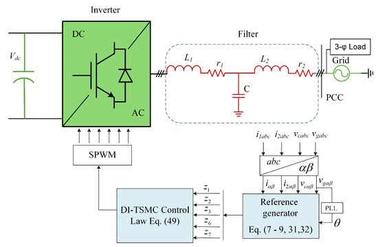
Figure 1.
Grid-connected inverter with an LCL filter.
3. Design of Nonlinear Controllers
3.1. Sliding Mode Control
The design of sliding mode control involves the formulation of the sliding surface (SS), which is a mathematical construct, mainly a function of the system state variables, and is designed to represent the dynamic behavior of the system. As we have defined three error terms representing current from the inverter current output (), grid current (), and capacitor voltage (), involving all of these in sliding manifold design will ensure accurate reference tracking and improve the control performance.
where and are the SS coefficients. Taking the time derivative of the SS in (20) gives
Now, putting in the respective error dynamics from (14), (16) and (19) gives
The control objective of the SMC is to derive the system state to the SS in finite time and stay there. To ensure this, Gao et al. in [] presented a reaching law that guarantees finite time convergence of the system trajectories towards SS. To reaching law is stated as
Here, k demonstrates the positive gain that derives the system states towards SS, defines the convergence rate, and is a signum function that ensures robustness. The Sign function can be given as
Now, substituting (23) into (22) gives
Further solving for the control results in
Now, using the boundary layer approach and replacing the signum function with saturation gives
3.1.1. Chattering Analysis
In SMC-based control, chattering is a primary concern that degrades control performance. As shown in Figure 2, chattering is characterized by high-frequency oscillation in the control signal in the vicinity of the SS. The system trajectories cross the SS repeatedly in rapid succession instead of converting and remaining on it. The primary cause of the chattering in the SMC control signal is due to the use of the Signum function, which is used to attain superior control performance in the presence of external disturbances. However, the Signum function introduces discontinuous switching between two states depending on the sign of the sliding variable. The rapid discontinuous switching is ideal in theory, but impossible to realize in practical systems due to the limited bandwidth of the actuators and the presence of system delays. To mitigate the chattering problem, the boundary layer approach is utilized in which the Signum function is replaced with a Saturation function. This approach introduces a narrow region around the vicinity of the SS.
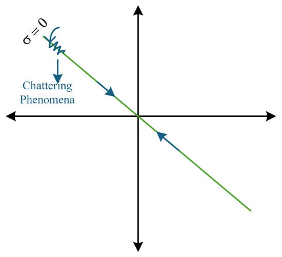
Figure 2.
Phase-plane trajectory exhibiting chattering phenomena.
3.1.2. Stability Analysis
The capability of the designed control technique to stabilize the system under external disturbances can be investigated using Lyapunov’s stability theorem []. In GCI system applications, Lyapunov’s stability theorem is an incredibly useful strategy for evaluating the controller behavior by studying a scalar function known as the Lyapunov function []. Let us define the following Lyapunov candidate function denoted by V:
Taking a time derivative of (27) gives
Next, putting the value of from (22) in (28), we get
Further substituting the final control law from (25) in (29) gives
It is evident that the SMC law in (25) is negative definite, and based on the Lyapunov stability criteria, the GCI system controlled by this SMC law is globally asymptotically stable.
3.2. Integral Terminal Sliding Mode Control
Terminal SMCs offer promising features compared to traditional SMCs, which suffer from chattering problems []. However, terminal SMC can be affected by singularity problems, which may lead to system instability. Therefore, integral terminal SMC (IT-SMC) is presented, which can maintain the system’s stability, solve the singularity problems, and enhance controller performance, specifically in eliminating the SSE. As in designing control, the core objective of the proposed method is to inject a high-quality sinusoidal current into the utility grid under external disturbances. Therefore, in the IT-SMC design procedure, the integral of the inverter and grid side current error terms are considered as
where and are positive integers and denote the convergence rate. Now, redesigning the SS for IT-SMC includes the integral part defined in (32) and (33) leads to
Taking the time derivative of (34) gives
Substituting the error dynamics from (14), (16), (19), (32) and (33), Equation (35) can be expressed as
Following the control law simplification procedure adopted for SMC, the IT-SMC control law can be written as
Now, to examine the stability of the GCI with an LCL filter, let us take the following Lyapunov function
Now, putting the value of from (36) into (39), we can obtain
Next, substituting the final control law from (37) in (40) and solving it gives
The IT-SMC control law is negative definite and can ensure the global asymptotic stability of the LCL-type GCI systems.
3.3. Double Integral Terminal Sliding Mode Control
In LCL-type grid-connected Inverter (GCI) systems, precise control is required to ensure low steady-state error (SSE), minimal overshoot, and high disturbance rejection under weak grid conditions. In this study, a double integral terminal sliding mode control (DIT-SMC) is constructed to further improve tracking accuracy and better suppress grid disturbances, particularly under the simultaneous occurrence of grid impedance variation and grid voltage distortions. It is important to note that conventional terminal sliding mode control can suffer from singularity issues near the equilibrium point, where control signals may become unbounded or unstable. To overcome this challenge, the control design has been modified to prevent such problematic behavior by ensuring that control signals remain well-defined and stable at all times, especially near the equilibrium. This is achieved by introducing a small region around the equilibrium point where the control smoothly transitions to a simpler form, thereby avoiding abrupt changes or infinite values. Additionally, sharp switching actions are replaced with smooth functions to maintain bounded and stable control signals throughout the system operation. These modifications ensure stable and robust control performance even in the vicinity of the equilibrium point. To achieve this, an integral of the inverter side current as well as the grid current is added in (32) and (33), respectively.
The SS is constructed from the linear combination of error terms defined in (7)–(9) and (43), (44), resulting in
Taking the time derivative of (45) gives
After further simplification, the SS results in
Now, following the same method to simplify and extract final control adopted for SMC and IT-SMC, we can obtain DI-TSMC as
To analyze the stability of the GCI system the same constraints defined for SMC and ITSMC, the DITSMC stability analysis results are as follows:
The Lyapunov function results in a negative definite, which clearly shows that an LCL-type GCI system controlled using DI-TSMC control is globally asymptotically stable.
4. Simulation Results
To simulate and verify the DIT-SMC control performance for an LCL-type GCI system under grid distortion and inductance variation, the MATLAB/Simulink Version R2023b platform is utilized. The parameters of the GCI system used in simulations are demonstrated as part of Table 1, and the DIT-SMC controller specifications are listed in Table 2. The control performance of the different controllers is compared with the proposed controller under several conditions. To validate the effectiveness of the proposed method, its performance is tested under four operating conditions.

Table 1.
GCI system parameters.

Table 2.
DIT-SMC controller parameters.
4.1. Reference Tracking Performance Evaluation
The efficiency of the DIT-SMC is analyzed at a step change of 10 A in the grid current reference and compared with the SMC and IT-SMC. Figure 3 illustrates the steady-state reference tracking accuracy where the SMC controller exhibits large SSE, leading to poor grid current quality, making it impractical for the steady operation of the GCI system with an LCL filter with external disturbances. To add to this, the results in Figure 4 depict that, at the step change of 10 A, the controller reference tracking required considerable performance improvement. The waveform in Figure 5 reveals that the DIT-SMC reference tracking performance is superior, and it maintains a high-quality grid current compared to the SMC and IT-SMC.
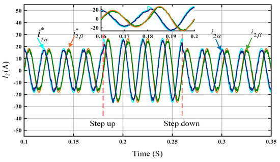
Figure 3.
Steady-state reference tracking performance using SMC.
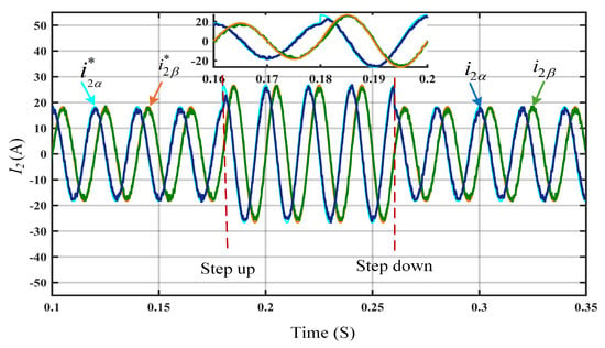
Figure 4.
Steady-state reference tracking performance using IT-SMC.
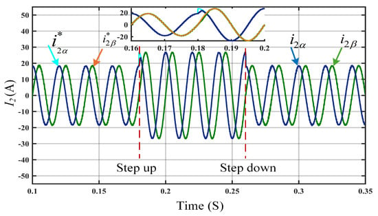
Figure 5.
Steady-state reference tracking performance using DIT-SMC.
4.2. Steady-State Performance Analysis
In the next step, the DIT-SMC control results are presented to further validate controller performance under steady-state conditions. The waveform for the grid-injected current and the grid voltage presented in Figure 6 illustrate that the alpha and beta components of the grid current are precisely synchronized with the respective grid-voltage components. Furthermore, the Total Harmonic Distortion (THD) of the current injected into the grid is measured using the Fast Fourier Transform (FFT) tool in Simulink, yielding a low THD of only 0.79%. The presence of interharmonic components, as illustrated in Figure 7, reflects the non-ideal behaviour of the inverter and the effects of grid impedance.
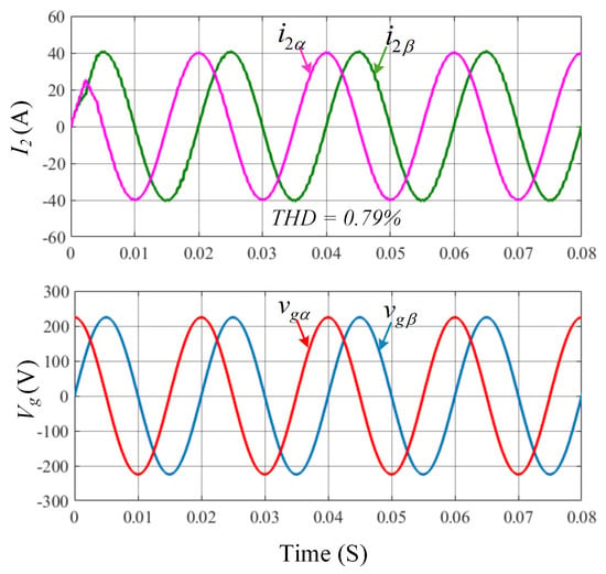
Figure 6.
Waveform for current injected into the grid and grid voltage using DIT-SMC.
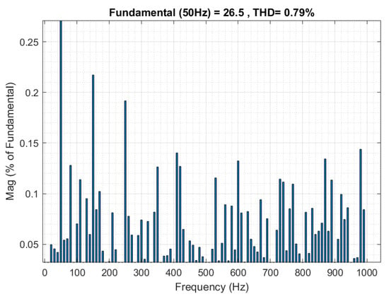
Figure 7.
Fast Fourier Transform of grid-injected current using DIT-SMC in steady-state conditions.
4.3. Performance Under External Disturbances
The performance of the controller severely degrades under the inductance variation of the grid, and the distortion of the grid voltage of the 3rd, 5th, 7th, 9th and 11th harmonic components. In particular, during the co-occurrence of grid inductance and voltage disturbances, as illustrated in Figure 8, there is only THD in the grid current, satisfying the IEEE grid connection standard restrictions. Figure 9 presents the results obtained when a resistive–inductive (RL) load is connected to the inverter output through the LCL filter. Each phase is equipped with a 1 ohm resistor and a 2.7 mH inductor.
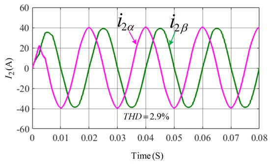
Figure 8.
Grid current waveform under grid inductance and voltage distortion.
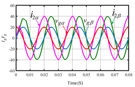
Figure 9.
Controller performance when the inverter is connected to RL load.
5. Hardware-in-Loop Experimental Validation
The GCI system with an LCL filter is prone to instability under external disturbances; therefore, the real-time performance analysis of the DIT-SMC is crucial to ensure system stability. For this purpose, to validate the controller effectiveness illustrated through simulation results, the OPAL-RT hardware-in-loop (HIL) validation is performed, as shown in Figure 10. The OPAL-RT real-time simulator OP5707XG utilizes virtex-7 FPGA, Montreal, QC, Canada which provides the fastest and most accurate closed-loop connection between the plant and the controller. A three-phase inverter with an LCL filter was constructed and integrated into the OPAL-RT system to evaluate the controller’s real-time performance. The designed system parameters are listed in Table 1 while the controller parameters are presented in Table 2. The experimental results of DIT-SMC for the current injected into the grid are presented in Figure 11a, which authenticates the precision of the simulation results. Furthermore, the proposed controller reference tracking waveform at the step change of 10 A shown in Figure 11b confirms that the controller maintains close to zero SSE without degrading the current quality. The results of the current delivered into the grid and grid voltage waveform are depicted in Figure 12, where the current and voltage for the respective phases are perfectly aligned, ensuring a unity power factor. In weaker grids, the GCI system at the resonance frequency is susceptible to instability. In particular, when the resonance frequency matches one-sixth of the sampling frequency, the system is hardly stable []. To consider these circumstances, the proposed controller performance is examined by inserting 2 mH inductance between the LCL filter and keeping the resonance frequency maintained at 2000 Hz (). The current waveform under this scenario is presented in Figure 13a, showing that the controller still maintains a high-quality grid current. Finally, the proficiency of the proposed DIT-SMC method is assessed under ultra-weak grid conditions where an extreme variation of 6 mH in grid inductance and distortion in grid voltage of 3rd, 5th, 7th, 9th and 11th order harmonics is considered. The results during the co-occurrence of the grid voltage and inductance variations are demonstrated in Figure 13b, where the THD in grid current is , proving the robustness of the controller. The performance of the proposed controller is evaluated under varying external load conditions to assess its robustness and stability. The results, as illustrated in Figure 14, demonstrate that the controller effectively maintains system performance, thereby validating the effectiveness and reliability of the proposed control method in the presence of load disturbances.
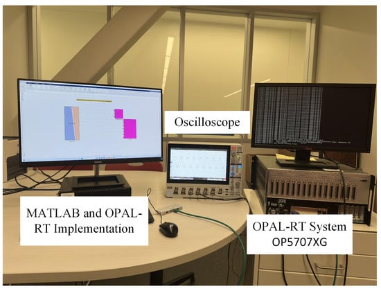
Figure 10.
Hardware-in-loop setup of OAPL-RT system.
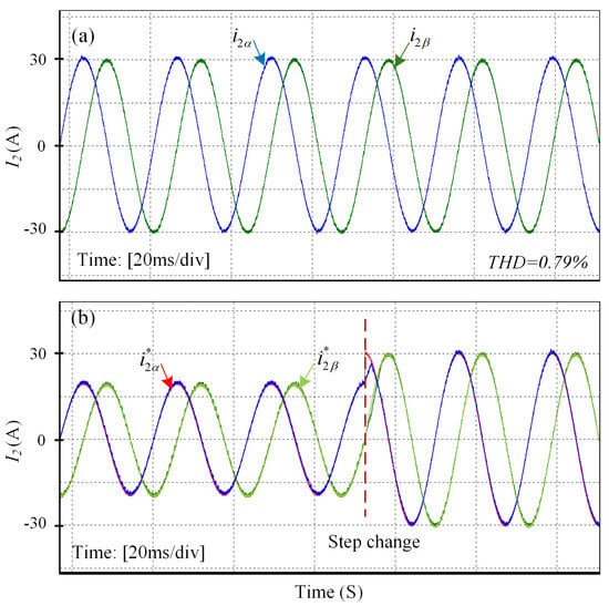
Figure 11.
(a) Steady-state waveform of current injected into the grid. (b) Reference tracking waveform at the step change of 10 A using DIT-SMC.
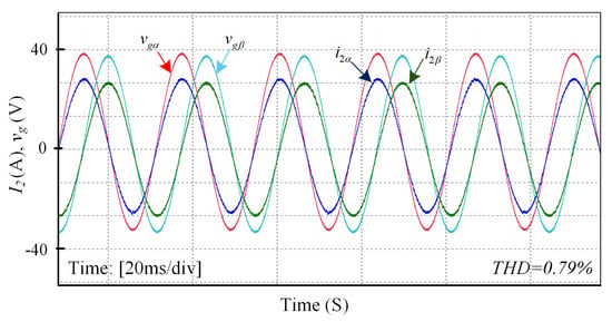
Figure 12.
Steady-state grid current and grid voltage waveform.
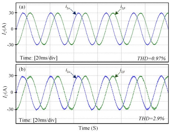
Figure 13.
(a) Grid current waveform at the resonance frequency of 2000 Hz. (b) Grid current results during co-occurrence of inductance variation and voltage distortions.
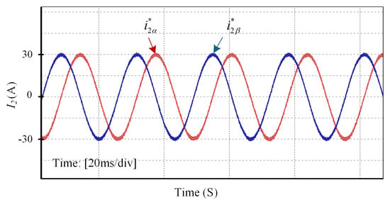
Figure 14.
Grid current waveform in the presence of the external load.
Evaluation Under Weaker Grid
Next, to evaluate the performance of the proposed controller, the DIT-SMC is compared with existing controllers. The experimental waveforms for grid current, grid voltage, and the grid current error using the SMC are shown in Figure 15a. The grid current THD is 2.3%, while the amplitude of the grid current error is 5.2 A. It is evident from Figure 15a that the drift in the SS led to an increase in the SSE. In reference [], the multi-resonant SMC (MRSMC) is implemented to enhance the reference tracking performance; the error waveform for this technique is shown in Figure 15b. Although the results are better compared to SMC, an error with an amplitude of 3.5 A still exists. The error minimization performance of the controller needs to be perfect for maintaining system stability; therefore, DIT-SMC is presented to reduce the SSE. The waveforms illustrated in Figure 15c are evidence that the adoption of the DIT-SMC controller can eliminate the SSE effectively under worse grid operating conditions. Furthermore, a comparison of the controllers is listed in Table 3, where it can be clearly seen that the proposed method has shown superior performance.
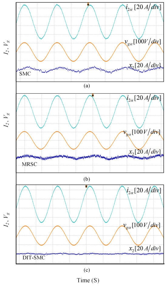
Figure 15.
Experimental results for reference tracking error comparison (a) SMC, (b) MRSMC and (c) DIT-SMC.

Table 3.
Comparative study with recent state-of-the-art control methods.
6. Conclusions
In this article, a robust double integral terminal sliding mode control (DIT-SMC) is presented for a three-phase inverter connected to an ultra-weak grid via an LCL filter. A mathematical model for the designed controller has been developed in the frame of reference without adopting any damping strategy to enhance the control performance and minimize the computational complexity of the synchronous reference frame. During analysis of the effectiveness of the DIT-SMC control, its reference tracking performance at a 10 A step change was compared with traditional SMCs and integral terminal-based SMCs; the newly designed control exhibits superior grid current quality and demonstrates excellent reference tracking. Furthermore, the DIT-SMC method ensures the stability of the GCI system at the resonance frequency of , even under significant variations in grid inductance. To further evaluate the control performance under ultra-weak grid conditions, scenarios involving substantial inductance variations along with grid voltage distortions were simulated. Under these challenging conditions, the total harmonic distortion (THD) of the grid current was maintained at only 2.9%, thereby confirming the robustness of the proposed control method. The controller’s performance was also assessed in the presence of an external load, during which the grid-connected inverter (GCI) system exhibited excellent stability. Finally, to demonstrate the superiority of the proposed method over existing control techniques, a comparison of the current error signal was carried out. The DIT-SMC control strategy was implemented in the MATLAB/Simulink environment, and experimental validation was carried out using the OPAL-RT hardware-in-the-loop (HIL) platform.
Author Contributions
A.M.N. contributed to the conceptualization of the study, contributed in the manuscript writing, validation of results, and manuscript review. A.S. developed the methodology, implemented the software, performed the analysis, and prepared the original draft. M.J. supervised the project, provided methodological guidance, and contributed to project administration and manuscript editing. S.Z.A. provided resources and participated in the review process. All authors have read and agreed to the published version of the manuscript.
Funding
This research was funded by Prince Sattam bin Abdulaziz University, project number (PSAU/2024/01/32106).
Data Availability Statement
The original contributions presented in this study are included in the article. Further inquiries can be directed to the corresponding author.
Acknowledgments
The authors extend their appreciation to Prince Sattam bin Abdulaziz University for funding this research work through the project number (PSAU/2024/01/32106).
Conflicts of Interest
The authors declare no conflicts of interest.
Abbreviations
The following abbreviations are used in this manuscript:
| GCI | Grid-connected inverter |
| SMC | Sliding mode control |
| IT-SMC | Integral terminal sliding mode control |
| DIT-SMC | Double integral terminal sliding mode control |
| SSE | Steady-state-error |
| THD | Total harmonic distortions |
| SS | Sliding surface |
| FFT | Fast Fourier Transform |
References
- Rocabert, J.; Luna, A.; Blaabjerg, F.; Rodriguez, P. Control of power converters in AC microgrids. IEEE Trans. Power Electron. 2012, 27, 4734–4749. [Google Scholar] [CrossRef]
- Song, W.; Dong, Y.; He, G.; Zhou, Z. Fixed-time robust fractional-order sliding mode control strategy for grid-connected inverters based on weighted average current. Energies 2024, 17, 4577. [Google Scholar] [CrossRef]
- Sun, H.; Guo, Q.; Qi, J.; Ajjarapu, V.; Bravo, R.; Chow, J.; Li, Z.; Moghe, R.; Nasr-Azadani, E.; Tamrakar, U.; et al. Review of challenges and research opportunities for voltage control in smart grids. IEEE Trans. Power Syst. 2019, 34, 2790–2801. [Google Scholar] [CrossRef]
- Agorreta, J.L.; Borrega, M.; López, J.; Marroyo, L. Modeling and control of N-Paralleled grid-connected inverters with LCL filter coupled due to grid impedance in PV plants. IEEE Trans. Power Electron. 2010, 6, 770–785. [Google Scholar]
- Rockhill, A.A.; Liserre, M.; Teodorescu, R.; Rodriguez, P. Grid-filter design for a multi-megawatt medium-voltage voltage-source inverter. IEEE Trans. Ind. Electron. 2010, 58, 1205–1217. [Google Scholar] [CrossRef]
- Tang, Y.; Loh, P.C.; Wang, P.; Choo, F.H.; Gao, F. Exploring inherent damping characteristic of LCL-filters for three-phase grid-connected voltage source inverters. IEEE Trans. Power Electron. 2011, 27, 1433–1443. [Google Scholar] [CrossRef]
- Azghandi, L.A.; Barakati, S.M.; Yazdani, A. Impedance-based stability analysis and design of a fractional-order active damper for grid-connected current-source inverters. IEEE Trans. Sustain. Energy 2021, 12, 599–611. [Google Scholar] [CrossRef]
- Yang, T.; Wang, Q.; Xie, Z.; Zhang, X.; Chang, L. Digital current controller with a novel active damping design for IPMSM. IEEE Trans. Energy Convers. 2022, 37, 185–197. [Google Scholar] [CrossRef]
- Chen, W.; Zhang, Y.; Tu, Y.; Shen, K.; Liu, J. Active damping control for LCL filters with inverter-side current feedback only. IEEE Trans. Power Electron. 2022, 37, 10065–10069. [Google Scholar] [CrossRef]
- Kouchaki, A.; Nymand, M. Analytical design of passive LCL filter for three-phase two-level power factor correction rectifiers. IEEE Trans. Power Electron. 2018, 33, 3012–3022. [Google Scholar] [CrossRef]
- Guan, Y.; Wang, Y.; Xie, Y.; Liang, Y.; Lin, A.; Wang, X. The dual-current control strategy of grid-connected inverter with LCL filter. IEEE Trans. Power Electron. 2018, 34, 5940–5952. [Google Scholar] [CrossRef]
- Li, M.; Zhang, X.; Guo, Z.; Wang, J.; Wang, Y.; Li, F.; Zhao, W. The control strategy for the grid-connected inverter through impedance reshaping in q-axis and its stability analysis under a weak grid. IEEE J. Emerg. Sel. Topics Power Electron. 2021, 9, 3229–3242. [Google Scholar] [CrossRef]
- Li, G.; Ma, F.; Luo, A.; He, Z.; Wu, W.; Wei, X.; Zhu, Z.; Guo, J. Virtual impedance-based virtual synchronous generator control for grid-connected inverter under weak grid situations. IET Power Electron. 2018, 11, 2125–2132. [Google Scholar] [CrossRef]
- Gulur, S.; Iyer, V.M.; Bhattacharya, S. A dual-loop current control structure with improved disturbance rejection for grid-connected converters. IEEE Trans. Power Electron. 2019, 34, 10233–10244. [Google Scholar] [CrossRef]
- Akhavan, A.; Vasquez, J.C.; Guerrero, J.M. A robust method for controlling grid-connected inverters in weak grids. IEEE Trans. Circuits Syst. II Express Briefs 2020, 68, 1333–1337. [Google Scholar] [CrossRef]
- Tang, C.; Zhou, K.; Shu, Y.; He, Q.; Chen, Q. Analysis and design of multiple resonant current control for grid-connected converters. IEEE J. Emerg. Sel. Topics Power Electron. 2021, 10, 2539–2546. [Google Scholar] [CrossRef]
- Wang, X.; Wang, D.; Zhou, S. A control strategy of LCL-type grid-connected inverters for improving the stability and harmonic suppression capability. Machines 2022, 10, 1027. [Google Scholar] [CrossRef]
- Maganti, S.; Padhy, N.P. A feedback-based flexible compensation strategy for a weak-grid-tied current-controlled converter under unbalanced and harmonic conditions. IEEE Trans. Ind. Appl. 2022, 58, 7739–7753. [Google Scholar] [CrossRef]
- Komurcugil, H.; Biricik, S.; Bayhan, S.; Zhang, Z. Sliding mode control: Overview of its applications in power converters. IEEE Ind. Electron. Mag. 2020, 15, 40–49. [Google Scholar] [CrossRef]
- Wu, L.; Liu, J.; Vazquez, S.; Mazumder, S.K. Sliding mode control in power converters and drives: A review. IEEE/CAA J. Autom. Sinica 2021, 9, 392–406. [Google Scholar] [CrossRef]
- Hou, T.; Jiang, Y.; Cai, Z. Study on the resonance characteristics and active damping suppression strategies of multi-inverter grid-connected systems under weak grid conditions. Energies 2024, 17, 5889. [Google Scholar] [CrossRef]
- Zheng, Y.; Deng, H.; Liu, X.; Guan, Y. Sliding mode observer-based phase-locking strategy for current source inverter in weak grids. Energies 2024, 17, 4891. [Google Scholar] [CrossRef]
- Sufyan, A.; Jamil, M.; Ghafoor, S.; Awais, Q.; Ahmad, H.A.; Khan, A.A.; Abouobaida, H. A robust nonlinear sliding mode controller for a three-phase grid-connected inverter with an LCL filter. Energies 2022, 15, 9428. [Google Scholar] [CrossRef]
- Li, H.; Wu, W.; Huang, M.; Chung, H.S.H.; Liserre, M.; Blaabjerg, F. Design of PWM-SMC controller using linearized model for grid-connected inverter with LCL filter. IEEE Trans. Power Electron. 2021, 35, 12773–12786. [Google Scholar] [CrossRef]
- Dong, H.; Yang, X.; Gao, H.; Yu, X. Practical terminal sliding-mode control and its applications in servo systems. IEEE Trans. Ind. Electron. 2022, 70, 752–761. [Google Scholar] [CrossRef]
- Yu, X.; Feng, Y.; Man, Z. Terminal sliding mode control—An overview. IEEE Open J. Ind. Electron. Soc. 2020, 2, 36–52. [Google Scholar] [CrossRef]
- Gao, W.; Hung, J.C. Variable structure control of nonlinear systems: A new approach. IEEE Trans. Ind. Electron. 1993, 40, 45–55. [Google Scholar] [CrossRef]
- Sanders, S.R.; Verghese, G.C. Lyapunov-based control for switched power converters. IEEE Trans. Power Electron. 1992, 7, 17–24. [Google Scholar] [CrossRef]
- Komurcugil, H.; Kukrer, O. Lyapunov-based control for three-phase pwm ac/dc voltage-source converters. IEEE Trans. Power Electron. 1998, 13, 801–813. [Google Scholar] [CrossRef]
- Pan, D.; Ruan, X.; Bao, C.; Li, W.; Wang, X. Optimized controller design for LCL-type grid-connected inverter to achieve high robustness against grid-impedance variation. IEEE Trans. Ind. Electron. 2014, 62, 1537–1547. [Google Scholar] [CrossRef]
Disclaimer/Publisher’s Note: The statements, opinions and data contained in all publications are solely those of the individual author(s) and contributor(s) and not of MDPI and/or the editor(s). MDPI and/or the editor(s) disclaim responsibility for any injury to people or property resulting from any ideas, methods, instructions or products referred to in the content. |
© 2025 by the authors. Licensee MDPI, Basel, Switzerland. This article is an open access article distributed under the terms and conditions of the Creative Commons Attribution (CC BY) license (https://creativecommons.org/licenses/by/4.0/).